

Page 1
FormNo.3400-446RevB
ZMaster
®
Professional7000
SeriesRidingMower
With52inTURBOFORCE
Mower
ModelNo.74279TE—SerialNo.316000001andUp
®
RearDischarge
Registeratwww.T oro.com.
OriginalInstructions(EN)
*3400-446*B
Page 2
ThisproductcomplieswithallrelevantEuropean
directives;fordetails,pleaseseetheseparateproduct
specicDeclarationofConformity(DOC)sheet.
Thismanualidentiespotentialhazardsandhas
safetymessagesidentiedbythesafety-alertsymbol
(Figure2),whichsignalsahazardthatmaycause
seriousinjuryordeathifyoudonotfollowthe
recommendedprecautions.
Introduction
Thisrotary-blade,ridinglawnmowerisintended
tobeusedbyresidentialhomeownersor
professional,hiredoperators.Itisdesigned
primarilyforcuttinggrassonwell-maintained
lawnsonresidentialorcommercialproperties.It
isnotdesignedforcuttingbrushorforagricultural
uses.
Readthisinformationcarefullytolearnhowtooperate
andmaintainyourproductproperlyandtoavoid
injuryandproductdamage.Y ouareresponsiblefor
operatingtheproductproperlyandsafely.
YoumaycontactT orodirectlyatwww.Toro.com
forproductsafetyandoperationtrainingmaterials,
accessoryinformation,helpndingadealer,orto
registeryourproduct.
Wheneveryouneedservice,genuineToroparts,or
additionalinformation,contactanAuthorizedService
DealerorToroCustomerServiceandhavethemodel
andserialnumbersofyourproductready.Figure1
identiesthelocationofthemodelandserialnumbers
ontheproduct.Writethenumbersinthespace
provided.
g000502
Figure2
1.Safety-alertsymbol
Thismanualuses2wordstohighlightinformation.
Importantcallsattentiontospecialmechanical
informationandNoteemphasizesgeneralinformation
worthyofspecialattention.
1.Modelandserialnumberlocation
ModelNo.
SerialNo.
©2018—TheToro®Company
8111LyndaleAvenueSouth
Bloomington,MN55420
Figure1
g000935
Contactusatwww.Toro.com.
2
PrintedintheUSA
AllRightsReserved
Page 3

Contents
Safety.......................................................................4
SafeOperatingPractices....................................4
ToroRidingMowerSafety...................................6
SoundPressureLevel........................................6
SoundPowerLevel............................................6
VibrationLevel....................................................6
SafetyandInstructionalDecals..........................7
ProductOverview...................................................14
Controls...........................................................14
Operation................................................................16
AddingFuel......................................................16
BiodieselReady...............................................16
FillingtheFuelTank..........................................17
CheckingtheEngine-OilLevel..........................17
SwitchingtheFuelT anks..................................17
UsingtheRolloverProtectionSystem
(ROPS).........................................................17
ThinkSafetyFirst..............................................18
OperatingtheParkingBrake.............................19
StartingandStoppingtheEngine......................20
OperatingthePowerT akeoff(PTO)..................21
UsingtheSafety-InterlockSystem....................22
DrivingForwardorBackward............................22
StoppingtheMachine.......................................24
AdjustingtheHeight-of-Cut...............................24
AdjustingtheAnti-ScalpRollers........................24
PositioningtheSeat..........................................25
ChangingtheSeatSuspension.........................26
UnlatchingtheSeat..........................................26
PushingtheMachinebyHand..........................26
OperatingwiththeOverheatSensor.................27
TransportingtheMachine.................................27
LoadingtheMachine........................................27
UsingtheZStand™.........................................29
OperatingTips.................................................30
Maintenance...........................................................31
RecommendedMaintenanceSchedule(s)...........31
Pre-MaintenanceProcedures..............................32
ReleasingtheMower-DeckCurtain..................32
RemovingtheSheet-MetalGuard.....................32
Lubrication..........................................................33
GreasingtheMachine.......................................33
GreasingtheFrontCasterPivots......................33
AddingGrease.................................................33
AddingLightOilorSprayLubrication................33
GreasingtheMowerDeckandBelt
Idlers.............................................................33
EngineMaintenance...........................................35
ServicingtheAirCleaner..................................35
ServicingtheEngineOil....................................36
FuelSystemMaintenance...................................40
ServicingtheFuelFilterandWater
Separator......................................................40
ServicingtheFuelT ank.....................................40
ElectricalSystemMaintenance...........................41
ServicingtheBattery.........................................41
ServicingtheFuses..........................................43
DriveSystemMaintenance..................................43
AdjustingtheTracking......................................43
CheckingtheTirePressure...............................44
CheckingtheWheelLugNuts...........................44
CheckingtheWheel-HubSlottedNut................44
AdjustingtheCaster-PivotBearing...................45
ServicingtheGearbox......................................45
AdjustingtheElectricClutch.............................45
CoolingSystemMaintenance..............................47
ServicingtheCoolingSystem...........................47
BrakeMaintenance.............................................49
AdjustingtheParkingBrake..............................49
BeltMaintenance................................................49
InspectingtheBelts..........................................49
ReplacingtheMowerBelt.................................49
ReplacingthePTODriveBelt...........................50
ReplacingthePumpDriveBelt.........................51
ReplacingandTensioningtheAlternator
Belt................................................................51
ControlsSystemMaintenance.............................52
AdjustingtheControlHandleNeutral
Position.........................................................52
HydraulicSystemMaintenance...........................53
ServicingtheHydraulicSystem........................53
SettingtheHydraulicPumpNeutral
Position.........................................................55
MowerDeckMaintenance....................................57
LevelingtheMower..........................................57
ServicingtheCuttingBlades.............................59
Cleaning..............................................................62
CleaningundertheMower................................62
DisposingofWaste...........................................62
Storage...................................................................62
CleaningandStorage.......................................62
Troubleshooting......................................................64
Schematics.............................................................66
3
Page 4

Safety
ThismachinewasdesignedinaccordancewithEN
ISO5395:2013.
Improperuseormaintenancebytheoperatororowner
canresultininjury.Toreducethepotentialforinjury,
complywiththesesafetyinstructionsandalwayspay
attentiontothesafety-alertsymbol,whichmeans
Caution,Warning,orDanger—”personalsafety
instruction”.Failuretocomplywiththeinstructionmay
resultinpersonalinjuryordeath.
SafeOperatingPractices
Thisproductiscapableofamputatinghandsand
feetandthrowingobjects.Alwaysfollowallsafety
instructionstoavoidseriousinjuryordeath.
Training
•Readtheinstructionscarefully.Befamiliarwiththe
controlsandtheproperuseoftheequipment.
•Neverallowchildrenorpeopleunfamiliarwith
theseinstructionstousethelawnmower.Local
regulationscanrestricttheageoftheoperator.
•Nevermowwhilepeople,especiallychildren,or
petsarenearby.
•Keepinmindthattheoperatororuseris
responsibleforaccidentsorhazardsoccurringto
otherpeopleortheirproperty.
•Donotcarrypassengers.
•Alldriversshouldseekandobtainprofessional
andpracticalinstruction.Suchinstructionshould
emphasize:
–theneedforcareandconcentrationwhen
workingwithride-onmachines;
–controlofaride-onmachineslidingonaslope
willnotberegainedbytheapplicationofthe
controllevers.Themainreasonsforlossof
controlare:
◊insufcientwheelgrip,especiallyonwet
grass;
◊beingdriventoofast;
◊inadequatebraking;
◊thetypeofmachineisunsuitableforits
task;
◊lackofawarenessoftheeffectofground
conditions,especiallyslopes;
◊incorrecthitchingandloaddistribution.
Preparation
•Whilemowing,alwayswearsubstantial,
slip-resistantfootwearandlongtrousers.
•Thoroughlyinspecttheareawheretheequipment
istobeusedandremoveallobjectswhichmaybe
thrownbythemachine.
•Warning–Fuelishighlyammable.
–Storefuelincontainersspecicallydesigned
forthispurpose.
–Refueloutdoorsonlyanddonotsmokewhile
refuelling.
–Addfuelbeforestartingtheengine.Never
removethecapofthefueltankoraddfuel
whiletheengineisrunningorwhentheengine
ishot.
–Iffuelisspilled,donotattempttostartthe
enginebutmovethemachineawayfromthe
areaofspillageandavoidcreatinganysource
ofignitionuntilfuelvaporshavedissipated.
–Replaceallfueltanksandcontainercaps
securely.
•Replacefaultysilencers.
•Beforeusing,alwaysvisuallyinspecttoseethat
theblades,bladeboltsandcutterassemblyare
notwornordamaged.Replacewornordamaged
bladesandboltsinsetstopreservebalance.
•Onmulti-bladedmachines,takecareasrotating
onebladecancauseotherbladestorotate.
Operation
•Lightningcancausesevereinjuryordeath.If
lightningisseenorthunderisheardinthearea,do
notoperatethemachine;seekshelter.
•Bealert,slowdownandusecautionwhenmaking
turns.Lookbehindandtothesidebeforechanging
directions.
•Donotoperatetheengineinaconnedspace
wheredangerouscarbonmonoxidefumescan
collect.
•Mowonlyindaylightoringoodarticiallight.
•Beforeattemptingtostarttheengine,disengage
allbladeattachmentclutchesandshiftintoneutral.
•Donotuseonslopesgreaterthan15degrees.
•Rememberthereisnosuchthingasasafeslope.
Travelongrassslopesrequiresparticularcare.T o
guardagainstoverturning:
–donotstoporstartsuddenlywhenonaslope;
–useslowspeedsonslopesandduringtight
turns;
–stayalertforhumpsandhollowsandother
hiddenhazards;
•Usecarewhenpullingloadsorusingheavy
equipment.
–Useonlyapproveddrawbarhitchpoints.
4
Page 5

–Limitloadstothoseyoucansafelycontrol.
–Donotturnsharply.Usecarewhenreversing.
•Watchoutfortrafcwhencrossingornear
roadways.
•Stopthebladesrotatingbeforecrossingsurfaces
otherthangrass.
•Whenusinganyattachments,neverdirect
dischargeofmaterialtowardbystandersnorallow
anyonenearthemachinewhileinoperation.
•Neveroperatethemachinewithdamagedguards
orwithoutsafetyprotectivedevicesinplace.
•Donotchangetheenginegovernorsettingsor
overspeedtheengine.Operatingtheengine
atexcessivespeedcanincreasethehazardof
personalinjury.
•Beforeleavingtheoperator'sposition:
–disengagethepowertakeoffandlowerthe
attachments;
–changeintoneutralandsettheparkingbrake;
–shutofftheengineandremovethekey .
•Disengagedrivetoattachments,shutoffthe
engine,anddisconnectthesparkplugwire(s)or
removetheignitionkey
–beforeclearingblockagesoruncloggingchute;
–beforechecking,cleaningorworkingonthe
lawnmower;
–afterstrikingaforeignobject.Inspectthe
lawnmowerfordamageandmakerepairs
beforerestartingandoperatingtheequipment;
ifthemachinestartstovibrateabnormally
(checkimmediately).
•Disengagedrivetoattachmentswhentransporting
ornotinuse.
•Shutofftheengineanddisengagedriveto
attachment
–beforerefuelling;
–beforeremovingthegrasscatcher;
–beforemakingheightadjustmentunless
adjustmentcanbemadefromtheoperator's
position.
•Reducethethrottlesettingduringenginerun-out
and,iftheengineisprovidedwithashutoffvalve,
turnthefueloffattheconclusionofmowing.
•Allowtheenginetocoolbeforestoringinany
enclosure.
•Toreducetherehazard,keeptheengine,
silencer,batterycompartmentandfuelstorage
areafreeofgrass,leaves,orexcessivegrease.
•Checkthegrasscatcherfrequentlyforwearor
deterioration.
•Replacewornordamagedpartsforsafety .
•Ifyoumustdrainthefueltank,thisshouldbedone
outdoors.
•Onmulti-bladedmachines,takecareasrotating1
bladecancauseotherbladestorotate.
•Whenmachineistobeparked,storedorleft
unattended,lowerthecuttingmeansunlessa
positivemechanicallockisused.
MaintenanceandStorage
•Keepallnuts,bolts,andscrewstighttobesure
theequipmentisinsafeworkingcondition.
•Neverstoretheequipmentwithfuelinthetank
insideabuildingwherefumescanreachanopen
ameorspark.
5
Page 6

ToroRidingMowerSafety
Thefollowinglistcontainssafetyinformationspecic
toT oroproductsorothersafetyinformationthatyou
mustknowthatisnotincludedintheCENstandard.
•Engineexhaustcontainscarbonmonoxide,which
isanodorless,deadlypoisonthatcankillyou.Do
notrunengineindoorsorinanenclosedarea.
•Keepyourhands,feet,hairandlooseclothing
awayfromattachmentdischargearea,underside
ofmowerandanymovingpartswhileengineis
running.
•Donottouchequipmentorattachmentpartswhich
maybehotfromoperation.Allowtocoolbefore
attemptingtomaintain,adjust,orservice.
•Batteryacidispoisonousandcancauseburns.
Avoidcontactwithskin,eyesandclothing.Protect
yourface,eyes,andclothingwhenworkingwitha
battery.
•Batterygasescanexplode.Keepcigarettes,
sparksandamesawayfrombattery.
maycausedrivewheelstoslipandcauselossof
brakingandsteering.
•Alwaysavoidsuddenstartingorstoppingona
slope.Iftireslosetraction,disengagetheblades
andproceedslowlyofftheslope.
•Followthemanufacturer'srecommendations
forwheelweightsorcounterweightstoimprove
stability.
•Useextremecarewithgrasscatchersorother
attachments.Thesecanchangethestabilityofthe
machineandcauselossofcontrol.
SoundPressureLevel
Thisunithasasoundpressurelevelattheoperator’s
earof90dBA,whichincludesanUncertaintyV alue
(K)of1dBA.
Thesoundpressurelevelwasdeterminedaccording
totheproceduresoutlinedinENISO5395:2013.
•UseonlygenuineTororeplacementpartsto
ensurethatoriginalstandardsaremaintained.
•UseonlyToro-approvedattachments.Warranty
maybevoidedifusedwithunapproved
attachments.
SlopeOperation
•Donotmowslopesgreaterthan15degrees.
•Donotmowneardrop-offs,ditches,steepbanks
orwater.Wheelsdroppingoveredgescancause
rollovers,whichmayresultinseriousinjury,death
ordrowning.
•Donotmowslopeswhengrassiswet.Slippery
conditionsreducetractionandcouldcausesliding
andlossofcontrol.
•Donotmakesuddenturnsorrapidspeedchanges.
•Useawalkbehindmowerand/orahandtrimmer
neardrop-offs,ditches,steepbanksorwater.
•Reducespeedanduseextremecautiononslopes.
•Removeormarkobstaclessuchasrocks,tree
limbs,etc.fromthemowingarea.T allgrasscan
hideobstacles.
•Watchforditches,holes,rocks,dips,andrises
thatchangetheoperatingangle,asroughterrain
couldoverturnthemachine.
SoundPowerLevel
Thisunithasaguaranteedsoundpowerlevelof105
dBA,whichincludesanUncertaintyValue(K)of1
dBA.
Thesoundpowerlevelwasdeterminedaccordingto
theproceduresoutlinedinISO11094.
VibrationLevel
Hand-Arm
Measuredvibrationlevelforrighthand=3.1m/s
Measuredvibrationlevelforlefthand=3.1m/s
UncertaintyValue(K)=1.6m/s
Measuredvaluesweredeterminedaccordingtothe
proceduresoutlinedinENISO5395:2013.
WholeBody
Measuredvibrationlevel=0.90m/s
UncertaintyValue(K)=0.45m/s
Measuredvaluesweredeterminedaccordingtothe
proceduresoutlinedinENISO5395:2013.
2
2
2
2
2
•Avoidsuddenstartswhenmowinguphillbecause
themowermaytipbackwards.
•Beawarethatlossoftractionmayoccurgoing
downhill.Weighttransfertothefrontwheels
6
Page 7
SafetyandInstructionalDecals
Safetydecalsandinstructionsareeasilyvisibletotheoperatorandarelocatednearanyarea
ofpotentialdanger.Replaceanydecalthatisdamagedorlost.
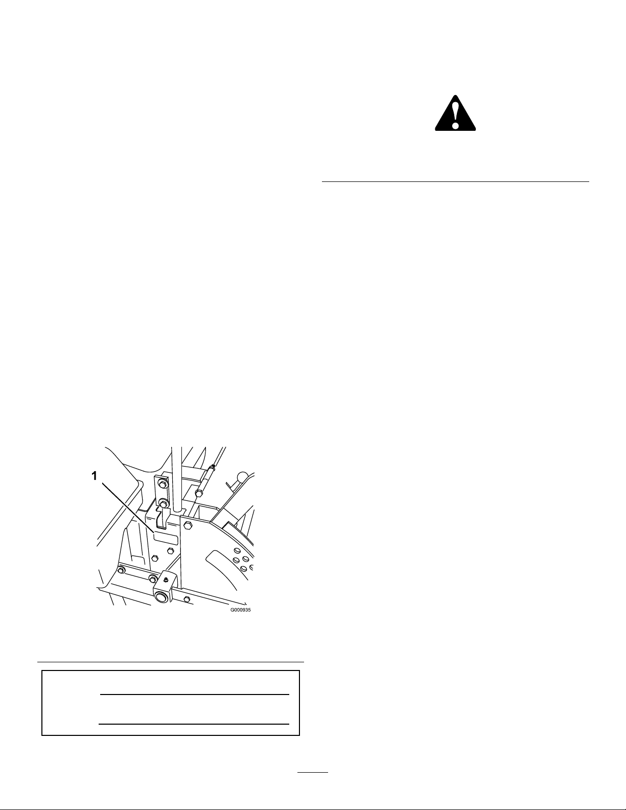
93-7818
decal93-7818
1.Warning—readtheOperator'sManualforinstructionson
torquingthebladebolt/nutto1 15to149N∙m(85to110
ft-lb).
93-8069
1.Hotsurface/burnhazard—stayasafedistancefromthe
hotsurface.
98-4387
1.Warning—wearhearingprotection.
decal107-2114
107-2114
decal93-8069
decal98-4387
decal107-3069
107-3069
1.Warning–thereisnorolloverprotectionwhentherollbaris
down.
2.Toavoidinjuryordeathfromarolloveraccident,keepthe
rollbarinthefullyraisedandlockedpositionandwear
theseatbelt.Lowertherollbaronlywhenabsolutely
necessary;donotwearthetheseatbeltwhentherollbaris
down.
3.ReadtheOperator'sManual;driveslowlyandcarefully.
decal104-2449
104-2449
7
Page 8
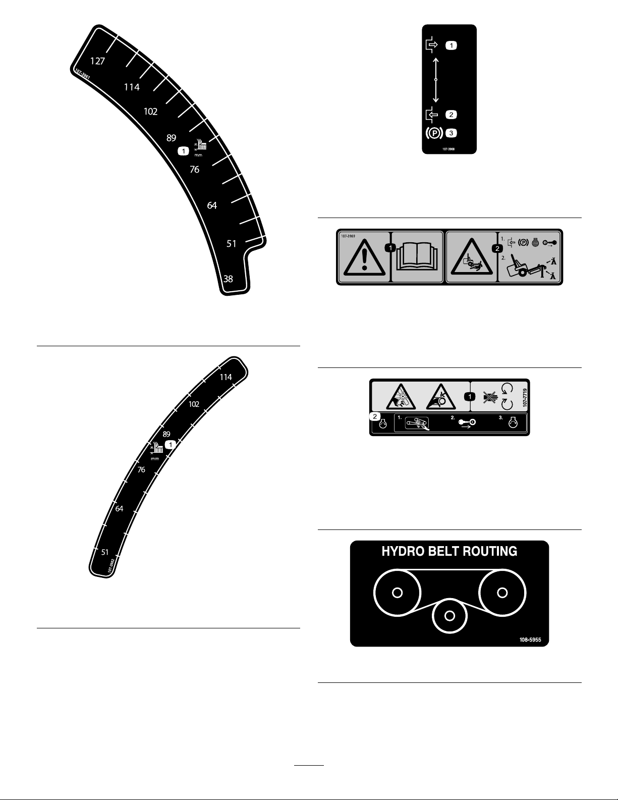
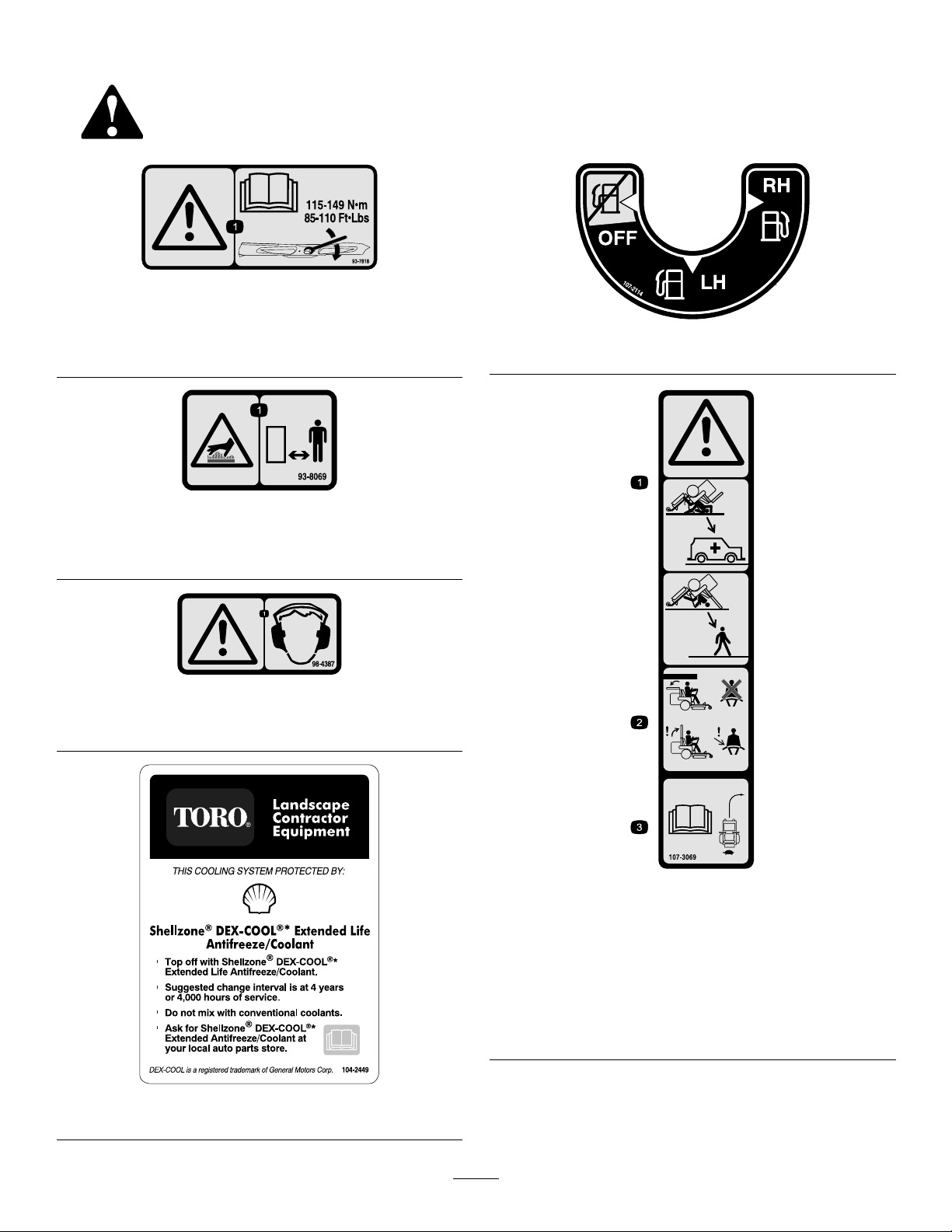
1.Heightofcutinmillimeters
decal107-3968
107-3968
1.Disengage3.Parkingbrake
2.Engage
decal107-3969
decal107-3961
107-3969
107-3961
1.Warning—readtheOperator'sManual.
2.Crushinghazard,mower—engagetheparkingbrake,stop
theengine,andremovetheignitionkeybeforeworking
underthemower.
decal107-7719
107-7719
1.Heightofcutinmillimeters
1.Cutting/dismembermenthazard,fanandentanglement
hazard,belt—stayawayfrommovingparts.
2.Beforestartingtheengine,cleangrassanddebrisfromthe
mowerbeltandpulleys,inserttheignitionkey,andstart
theengine.
decal107-3962
107-3962
decal108-5955
108-5955
8
Page 9
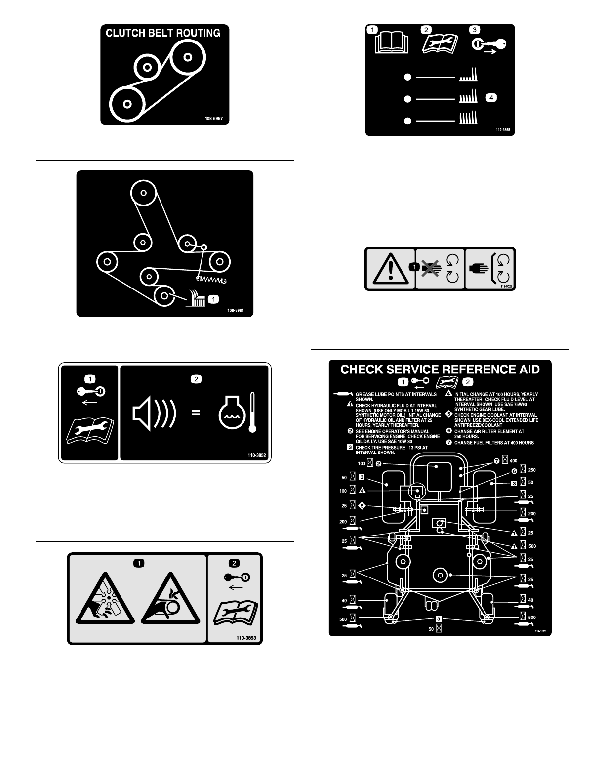
decal108-5957
108-5957
decal112-3858
112-3858
1.ReadtheOperator's
Manual.
3.Removetheignitionkey
beforeadjustingtheheight
ofcut.
2.Readtheinstructions
4.Heightofcutsettings.
beforeservicingor
performingmaintenance.
decal112-9028
112-9028
decal108-5981
108-5981
1.Warning—stayawayfrommovingparts;keepallguardsin
place.
1.Removetheignitionkey
andreadtheinstructions
beforeservicingor
performingmaintenance.
1.Cutting/dismemberment
hazard,fanand
entanglementhazard,
belt.
110-3852
2.Continuoustonesignals
theuserthatengineis
overheating.
110-3853
2.Removetheignitionkey
andreadtheinstructions
beforeservicingor
performingmaintenance.
decal110-3852
decal110-3853
114-1826
decal114-1826
1.Removetheignitionkey.2.Readtheinstructions
beforeservicingor
performingmaintenance.
9
Page 10
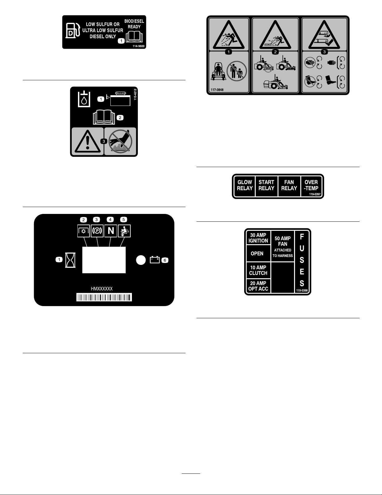
1.ReadtheOperator'sManual.
decal114-9600
114-9600
decal117-3848
117-3848
1.Thrownobjecthazard—keepbystandersasafedistance
fromthemachine
2.Thrownobjecthazard,mower-donotoperatewithoutthe
deector,dischargecoverorgrasscollectionsystemin
place.
3.Cutting/dismembermentofhandorfoot—stayawayfrom
decal115-4212
movingparts;keepallguardsandshieldsinplace.
115-4212
1.Hydraulicoillevel3.Warning—donottouchthe
hotsurface.
2.ReadtheOperator's
Manual.
116–5610
1.Hourmeter4.Neutral
2.Powertakeoff(PTO)5.Operatorpresenceswitch
3.Parkingbrake6.Battery
decal119-0397
119–0397
decal119-0398
decal116-5610
119–0398
10
Page 11
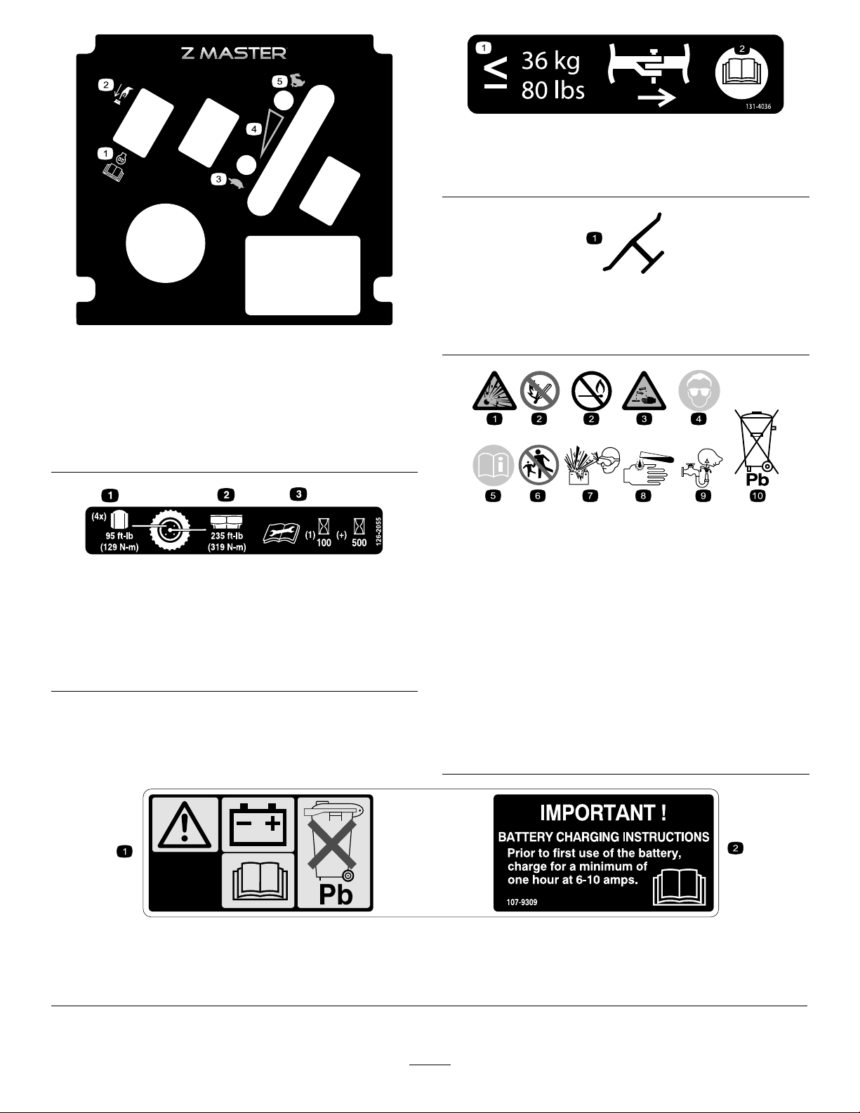
decal131-4036
131-4036
121–7562
1.Pushtostart4.Variablespeedcontrol
2.ReadtheOperator’s
5.Fast
Manualformore
informationonpreheating
theengine.
3.Slow
126-2055
1.Wheellugnuttorque129N∙m(95ft-lb)(4x)
2.Wheel-hubnuttorque319N∙m(235ft-lb)
3.ReadandunderstandtheOperator’smanualbefore
performinganymaintenance,checktorqueafterrst100
hoursthenevery500hoursthereafter.
1.Maximumdrawbarpull36
kg(80lb).
2.ReadtheOperator's
Manual.
decaloemmarkt
Manufacturer'sMark
decal121-7562
1.Indicatesthebladeisidentiedasapartfromtheoriginal
machinemanufacturer.
decalbatterysymbols
BatterySymbols
Someorallofthesesymbolsareonyourbattery
decal126-2055
1.Explosionhazard
2.Nore,opename,or
6.Keepbystandersasafe
7.Weareyeprotection;
smoking.
3.Causticliquid/chemical
8.Batteryacidcancause
burnhazard
4.Weareyeprotection9.Flusheyesimmediately
5.ReadtheOperator's
10.Containslead;donot
Manual.
distancefromthebattery.
explosivegasescan
causeblindnessandother
injuries
blindnessorsevereburns.
withwaterandgetmedical
helpfast.
discard.
107-9309
1.Warning—readtheOperator'sManualforinformationonchargingthebattery;containslead;donotdiscard.
2.ReadtheOperator'sManual.
11
decal107-9309
Page 12
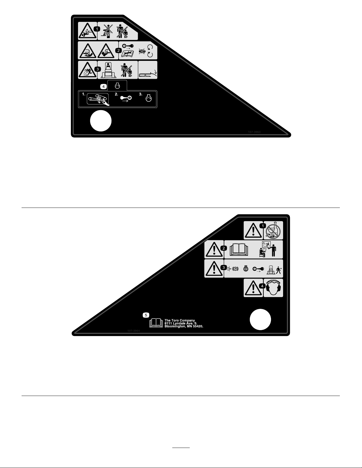
decal107-3963
107-3963
1.Cutting/dismemberment
hazard,mowerblade—do
notcarrypassengersand
keepbystandersaway.
2.Cutting/dismemberment
hazardofhandorfoot,
mowerblade—remove
theignitionkeyandread
theinstructionsbefore
servicingorperforming
maintenance;stayaway
frommovingparts.
3.Thrownobject
hazard—keepbystanders
asafedistancefromthe
machineandkeepthe
deectorinplace.
4.Beforestartingtheengine,
cleangrassanddebrisfrom
themowerbeltandpulleys,
inserttheignitionkey,and
starttheengine.
107-3964
1.Warning—donotusedrugsoralcohol.3.Warning—engagetheparkingbrake,
2.Warning—readtheOperator'sManual
andreceivetraining.
stoptheengine,andremovethe
ignitionkeybeforeleavingthe
machine.
4.Warning—wearhearingprotection.
12
decal107-3964
5.ReadtheOperator'sManual.
Page 13
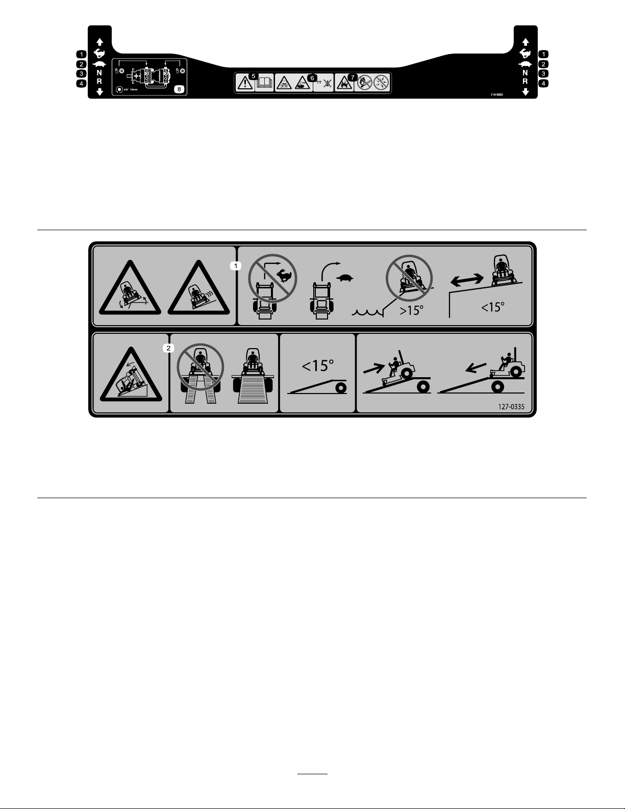
decal110-0820
110-0820
1.Fast
5.Warning—readtheOperator'sManual.
2.Slow6.Poisonandcausticliquid/chemicalburnhazard—keep
childrenasafedistancefromthebattery.
3.Neutral
7.Explosionhazard—nore,openames,orsmoking;avoid
sparks.
4.Reverse8.Tounlockthetractiondrive,turntheby-passvalve1complete
revolutioncounterclockwiseusinga16mmor5/8inch
wrench.
127–0335
decal127-0335
1.Tippinghazardonslopes—donotmakesudden,tightturns;
makeslow,wideturns;donotuseonslopesnearopenwater;
donotusethismachineonslopesgreaterthan15degrees.
2.Ramphazard—whenloadingontoatrailer,donotusedual
ramps;onlyuseasingularrampwideenoughforthemachine
andthathasaninclinelessthan15degrees;backupthe
ramp(inreverse)anddriveforwardofftheramp.
13
Page 14
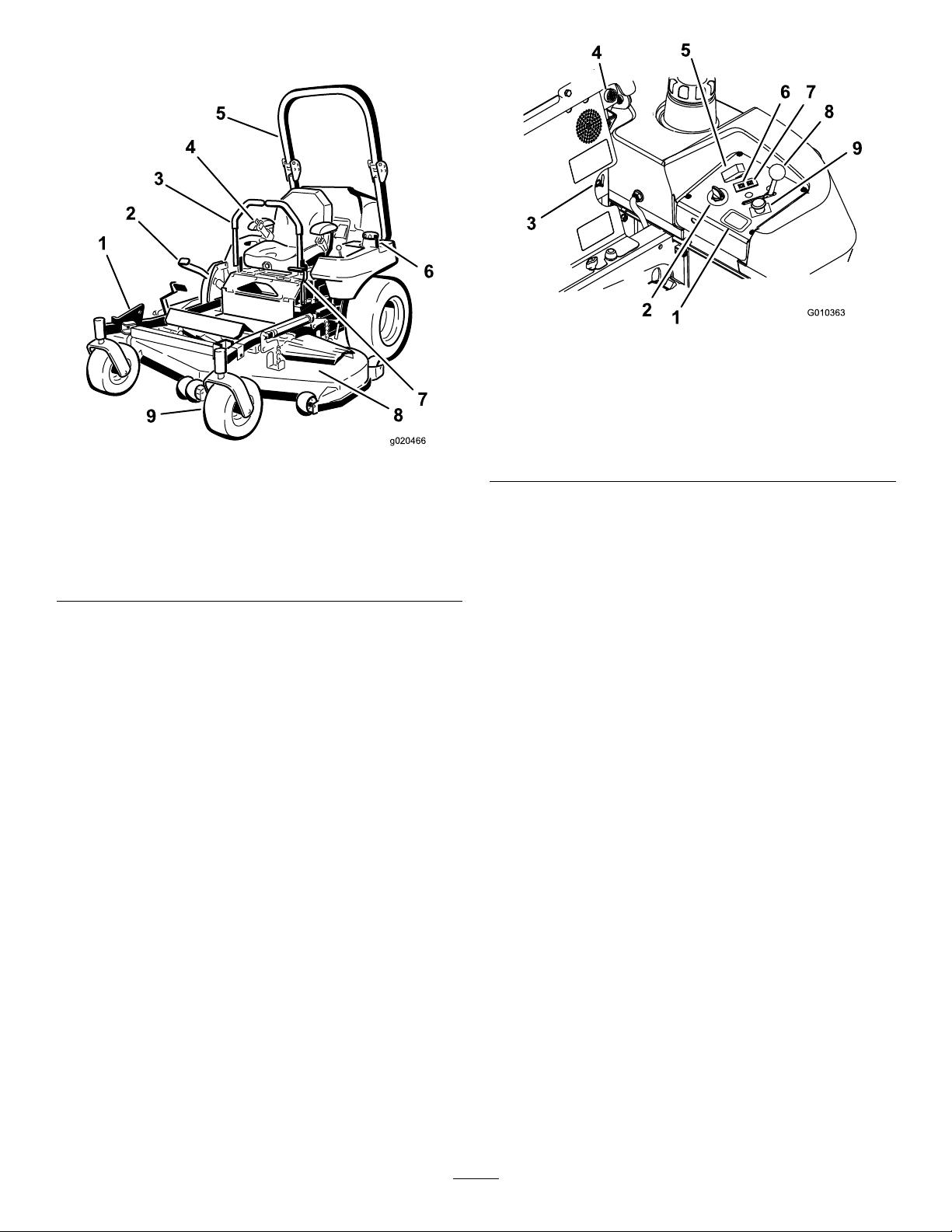
ProductOverview
g010363
Figure4
Figure3
1.ZStand
2.Height-of-cutlever
3.Motion-controllever8.Mowerdeck
4.Seatbelt9.Casterwheel
5.Rollbar
©
6.Fuelcap(bothsides)
7.Parking-brakelever
Controls
Becomefamiliarwithallthecontrolsbeforeyoustart
theengineandoperatethemachine(Figure3and
Figure4).
1.Hourmeter
2.Ignitionswitch7.Engine-temperaturelight
3.Fuel-selectorvalve8.Throttlecontrol
g020466
4.Audiblealarm
5.Glow-plugswitch
6.Glow-pluglight
9.PTOSwitch
HourMeter
Thehourmeterrecordsthenumberofhoursthe
enginehasoperated.Itoperateswhentheengine
isrunning.Usethesetimesforschedulingregular
maintenance(Figure4).
Safety-InterlockIndicators
Therearesymbolsonthehourmeterandtheyindicate
withablacktrianglethattheinterlockcomponentisin
thecorrectposition(Figure5).
BatteryIndicatorLight
WhentheignitionkeyisinitiallyturnedtotheRUN
positionforafewseconds,thebatteryvoltageis
displayedintheareawherethehoursarenormally
displayed.
Thebatterylightturnsonwhentheignitionisturned
onandwhenthechargeisbelowthecorrectoperating
level(Figure5).
14
Page 15

AudibleAlarm
Thismachinehasanaudiblealarmthatalertstheuser
toturnofftheengineorenginedamagecanoccur
fromoverheating.RefertoServicingtheCooling
SysteminCoolingSystemMaintenance(page47).
Fuel-SelectorValve
Figure5
1.Safety-interlocksymbols
2.Hourmeter
3.Batterylight
ThrottleControl
ThethrottlecontrolisvariablebetweenFASTand
SLOW.
Blade-ControlSwitch(PTO)
Theblade-controlswitch(PTO)isusedtoengage
theelectricclutchtodrivethemowerbladeswiththe
motion-controlleversinthecenter,unlockedposition.
Pulltheswitchuptoengagethebladesandrelease.
Todisengagetheblades,pushtheblade-control
switch(PTO)down.
Neutral-LockPosition
g009610
Thefuel-selectorvalveislocatedbehindtheseat.
Closethefuel-selectorvalvewhentransportingor
storingmower.
Movetheselectorvalvetotheleftorrightpositionfor
operation.
Attachments/Accessories
AselectionofToroapprovedattachmentsand
accessoriesisavailableforusewiththemachineto
enhanceandexpanditscapabilities.Contactyour
AuthorizedServiceDealerorDistributororgoto
www.T oro.comforalistofallapprovedattachments
andaccessories.
Tobestprotectyourinvestmentandmaintainoptimal
performanceofyourT oroequipment,countonT oro
genuineparts.Whenitcomestoreliability,T oro
deliversreplacementpartsdesignedtotheexact
engineeringspecicationofourequipment.Forpeace
ofmind,insistonTorogenuineparts.
TheNEUTRAL-LOCKpositionisusedwiththe
safety-interlocksystemandtodetermineNEUTRAL
position.
IgnitionSwitch
Thisswitchisusedtostartthemowerengineandhas
3positions:START,RUN,andOFF.
Glow-PlugLight
Theglowplugindicatorlightturnsonwhenthe
glow-plugbuttonisengaged(Figure4).
Glow-PlugSwitch
Thisswitchactivatestheglowplugsandisindicated
bytheglow-pluglight.Holddowntheglow-plugswitch
for10secondspriortostarting.
Engine-TemperatureLight
Theengine-temperaturelightcomesonwhenthe
engineisoverheating(Figure4).
15
Page 16

Operation
Note:Determinetheleftandrightsidesofthe
machinefromthenormaloperatingposition.
DANGER
Incertainconditions,fuelisextremely
ammableandhighlyexplosive.Areor
explosionfromfuelcanburnyouandothers
andcandamageproperty .
AddingFuel
Theenginerunsonclean,freshdieselfuelwith
aminimumoctaneratingof40.Purchasefuelin
quantitiesthatyoucanusewithin30daystoensure
fuelfreshness.
Usesummergradedieselfuel(No.2-D)at
temperaturesabove-7°C(20°F)andwintergrade
dieselfuel(No.1-DorNo.1-D/2-Dblend)below
-7°C(20°F).Useofwintergradedieselfuelatlower
temperaturesprovideslowerashpointandpour
pointcharacteristics,thereforeeasingstartabilityand
lesseningchancesofchemicalseparationofthefuel
duetolowertemperatures(waxappearance,which
maypluglters).
Useofsummergradedieselfuelabove-7°C
(20°F)contributestowardlongerlifeofthepump
components.
Important:Donotusekeroseneorgasoline
insteadofdieselfuel.Failuretoobservethis
cautionwilldamagetheengine.
WARNING
Fuelisharmfulorfatalifswallowed.
Long-termexposuretovaporscancause
seriousinjuryandillness.
•Avoidprolongedbreathingofvapors.
•Keepfaceawayfromnozzleandfueltank
orconditioneropening.
•Keepfuelawayfromeyesandskin.
•Fillthefueltankoutdoorsonlevelground,
inanopenarea,whentheengineiscold.
Wipeupanyfuelthatspills.
•Neverllthefueltankinsideanenclosed
trailer.
•Donotllthefueltankcompletelyfull.
Fillthefueltanktothebottomoftheller
neck.Theemptyspaceinthetankallows
fueltoexpand.Overllingmayresultin
fuelleakageordamagetotheengineor
emissionsystem(ifequipped).
•Neversmokewhenhandlingfuel,andstay
awayfromanopenameorwherefuel
fumesmaybeignitedbyaspark.
•Storefuelinanapprovedcontainerand
keepitoutofthereachofchildren.Never
buymorethana30-daysupplyoffuel.
•Alwaysplacefuelcontainersontheground
awayfromyourvehiclebeforelling.
•Donotllfuelcontainersinsideavehicle
oronatruckortrailerbedbecauseinterior
carpetsorplastictruckbedlinersmay
insulatethecontainerandslowthelossof
anystaticcharge.
•Whenpractical,removefuel-powered
equipmentfromthetruckortrailerand
refueltheequipmentwithitswheelsonthe
ground.
•Ifthisisnotpossible,thenrefuelsuch
equipmentonatruckortrailerfroma
portablecontainer,ratherthanfroma
fuel-dispensernozzle.
•Ifafuel-dispensernozzlemustbeused,
keepthenozzleincontactwiththerimof
thefueltankorcontaineropeningatall
timesuntilfuelingiscomplete.
BiodieselReady
Thismachinecanalsouseabiodieselblendedfuel
ofuptoB20(20%biodiesel,80%petrodiesel).The
petrodieselportionshouldbeloworultralowsulfur.
Observethefollowingprecautions:
•Thebiodieselportionofthefuelmeetspecication
ASTMD6751orEN14214.
16
Page 17
•TheblendedfuelcompositionshouldmeetASTM
D975orEN590.
fueltankrotatethefuel-selectorvalvetotheright-hand
location(Figure6)
•Paintedsurfacesmaybedamagedbybiodiesel
blends.
•UseB5(biodieselcontendof5%)orlesserblend
incoldweather.
•Monitorseals,hoses,gasketsincontactwithfuel
astheymaydegradeovertime.
•Fuellterpluggingmaybeexpectedforatime
afterconvertingtobiodieselblends.
•Contactyourdistributorifyouwishformore
informationonbiodiesel.
FillingtheFuelTank
Note:Donotllthefueltankcompletelyfull.Fillthe
fueltanktothebottomofthellerneck.Theempty
spaceinthetankallowsthegasolinetoexpand.
1.Shuttheengineoffandsettheparkingbrake.
2.Cleanaroundeachfuel-tankcapandremovethe
cap.Fillthefueltanktothebottomoftheller
neck.Thisspaceinthetankallowsthefuelto
expand.Donotllthefueltankcompletelyfull.
Closethefuel-selectorvalvebeforetransportingor
storingmachine.
3.Installthefuel-tankcapsecurely.Wipeupany
fuelthatmayhavespilled.
4.Ifpossible,llthefueltankaftereachuse.This
minimizespossiblebuildupofcondensation
insidethefueltank.
CheckingtheEngine-Oil Level
Beforeyoustarttheengineandusethemachine,
checktheoillevelintheenginecrankcase;referto
CheckingtheEngine-OilLevel(page37).
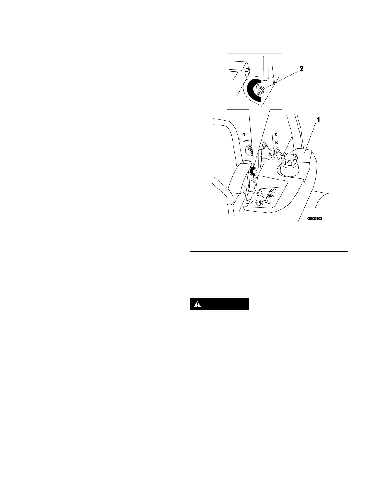
SwitchingtheFuelTanks
Important:Donotrunthemachineoutoffuel.
Thismaycauseenginedamageandrequirethe
fuelsystemtobechecked.
Thefuel-selectorvalveislocatedbehindtheleftside
oftheseat.
Figure6
1.Leftfueltank
2.Fuel-selectorvalve
UsingtheRollover ProtectionSystem(ROPS)
WARNING
Toavoidinjuryordeathfromrollover:keep
therollbarintheraisedlockedpositionand
usetheseatbelt.
Ensurethattherearpartoftheseatissecured
withtheseatlatch.
g000962
Theunithas2fueltanks.Onetankisontheleftside
andtheotherontherightside.Eachtankconnects
tothefuel-selectorvalve.Fromthereacommonfuel
lineleadstotheengine(Figure6).
Tousetheleftsidefueltankrotatethefuel-selector
valvetotheleft-handlocation.T ousetherightside
17
Page 18
WARNING
Thereisnorolloverprotectionwhentheroll
barisinthedownposition.
•Lowertherollbaronlywhenabsolutely
necessary.
•Donotweartheseatbeltwhentherollbar
isinthedownposition.
•Driveslowlyandcarefully.
•Raisetherollbarassoonasclearance
permits.
•Checkcarefullyforoverheadclearances
(i.e.,branches,doorways,electricalwires)
beforedrivingunderanyobjectsanddo
notcontactthem.
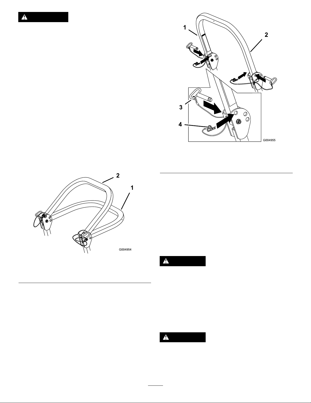
1.Removethehairpincottersandremovethe2
pins(Figure8).
2.Lowertherollbartothedownposition.There
are2downpositions.SeeFigure7forthe
positions.
g004955
Figure8
1.Rollbar3.Pin
2.Raisedposition4.Hairpincotter
Figure7
1.Fulldownposition2.Downpositionwithbagger
installed
3.Installthe2pinsandsecurethemwiththe
hairpincotters(Figure8).
4.Toraisetherollbar,removethehairpincotters
andremovethe2pins(Figure8).
5.Raisetherollbartotheuprightpositionand
installthe2pinsandsecurethemwiththe
hairpincotters(Figure8).
ThinkSafetyFirst
Pleasereadallsafetyinstructionsandsymbolsinthe
safetysection.Knowingthisinformationcouldhelp
youorbystandersavoidinjury .
g004954
DANGER
Operatingthemachineonwetgrassorsteep
slopescancauseslidingandlossofcontrol.
•Donotoperateonslopesgreaterthan15
degrees.
•Reducespeedanduseextremecautionon
slopes.
•Donotoperatethemachinenearwater.
DANGER
Wheelsdroppingoveredgescancause
rollovers,whichmayresultinseriousinjury,
death,ordrowning.
Donotoperatethemachineneardrop-offs.
18
Page 19
DANGER
OperatingtheParking
Operatingthemachinewhiletherollbaris
downmayleadtoseriousinjuryordeathin
theeventofarollover.
Alwayskeeptherollbarinthefullyraisedand
lockedpositionandusetheseatbelt.
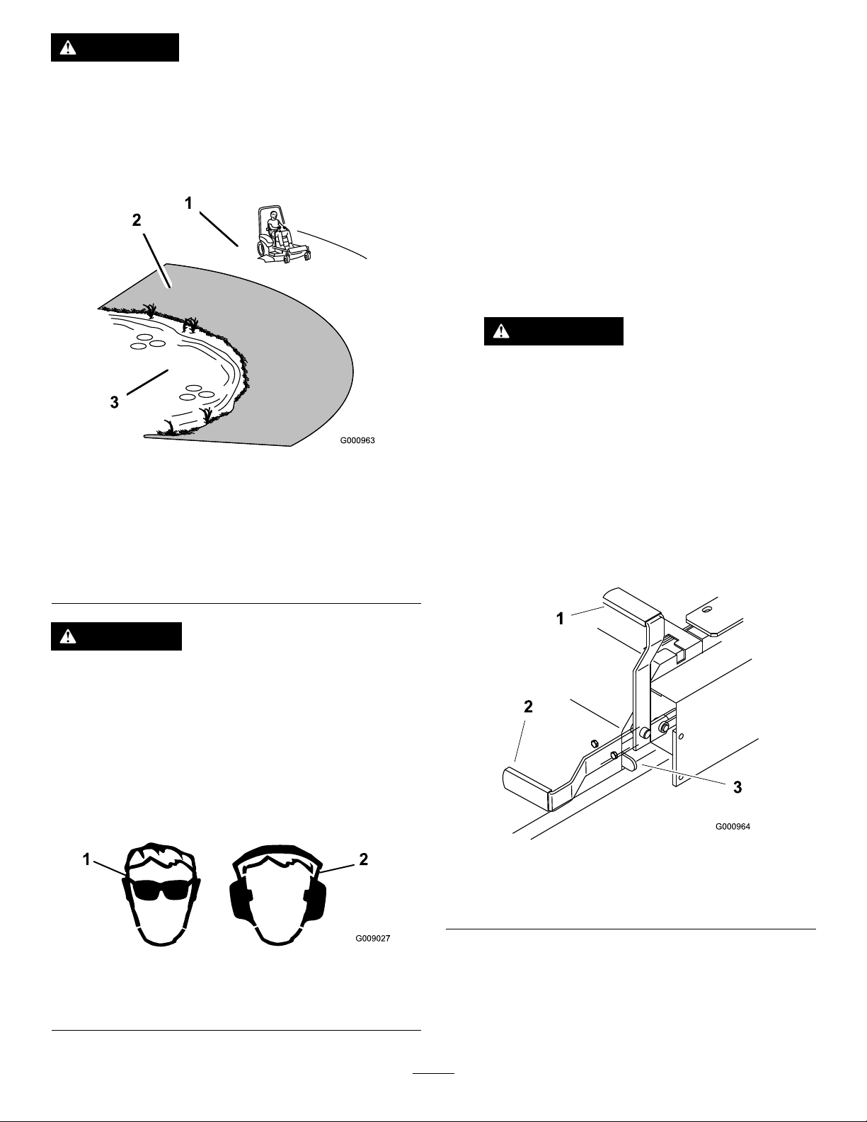
Figure9
1.SafeZone-usethe
ZMasterhereonslopes
lessthan15degreesor
atareas.
2.Usewalkbehindmower
and/orhandtrimmernear
drop-offsandwater.
3.Water
Brake
Alwayssettheparkingbrakewhenyoustopthe
machineorleaveitunattended.
SettingtheParkingBrake
1.Movethemotion-controllevers(Figure17)out
totheNEUTRAL-LOCKposition.
2.Pullupandbackontheparking-brakelever
tosettheparkingbrake(Figure11).The
parking-brakelevershouldstayrmlyinthe
engagedposition.
WARNING
Parkingbrakemaynotholdmachine
parkedonaslopeandcouldcause
personalinjuryorpropertydamage.
Donotparkonslopesunlesswheelsare
g000963
chockedorblocked
ReleasingtheParkingBrake
Pushforwardanddownontheparking-brakeleverto
releasetheparkingbrake(Figure1 1).Theparking
brakeisdisengagedandtheleverwillrestagainst
thebrakestop.
CAUTION
Thismachineproducessoundlevelsin
excessof85dBAattheoperatorsearandcan
causehearinglossthroughextendedperiods
ofexposure.
Wearhearingprotectionwhenoperatingthis
machine.
Wearprotectiveequipmentforyoureyes,ears,hands,
feet,andheadwhenusingthismachine.
Figure10
1.Warning—weareye
protection.
2.Warning—wearhearing
protection
g000964
Figure11
1.ONposition
2.OFFposition
g009027
3.Brakestop
19
Page 20
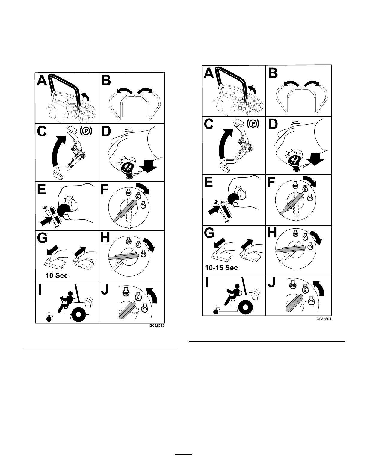
StartingandStoppingthe Engine
StartingtheEngineinNormal Weather
StartingtheEngineinCold Weather(Below-5°Cor23°F)
Note:Usethecorrectengineoilforthestarting
temperature;refertoServicingtheEngineOil(page
36).
Figure12
Important:Usestartingcyclesofnomorethan
30secondsperminutetoavoidoverheatingthe
startermotor.
Note:Additionalstartingcyclesmayberequired
whenstartingtheengineforthersttimeafterthefuel
systemhasbeencompletelywithoutfuel.
g032594
g032593
Important:Usestartingcyclesofnomorethan
30secondsperminutetoavoidoverheatingthe
startermotor.
Note:Donotusefuelleftoverfromthesummer.Use
onlyfreshwintergradedieselfuel.
20
Figure13
Page 21
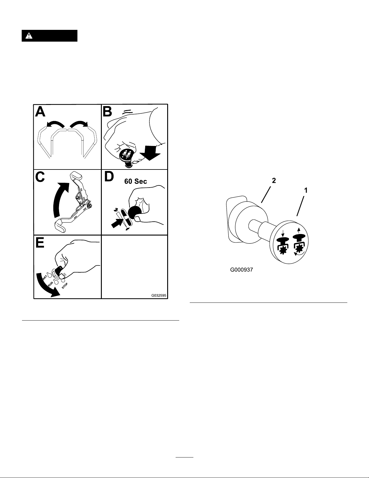
StoppingtheEngine
OperatingthePower
CAUTION
Childrenorbystandersmaybeinjuredifthey
moveorattempttooperatethemachinewhile
itisunattended.
Alwaysremovetheignitionkeyandsetthe
parkingbrakewhenleavingthemachine
unattended,evenifjustforafewminutes.
Takeoff(PTO)
Thepowertakeoff(PTO)switchstartsandstopsthe
mowerbladesandanypoweredattachments.
EngagingthePTO
1.Iftheengineiscold,allowtheenginetowarm
up5to10minutesbeforeengagingthePTO.
2.Whileseatedintheseat,releasethepressureon
thetractioncontrolleversandplaceinNEUTRAL.
3.PlacethethrottleintheFASTposition.
Note:EngagingthePTOwiththethrottleat
thehalforlesspositioncausesexcessivewear
tothedrivebelts.
4.Pulloutonthepowertakeoff(PTO)switchto
engageit(Figure15).
Figure14
Important:Makesurethatyouclosethe
fuel-shutoffvalvebeforetransportingorstoring
themachine,asfuelleakagemayoccur.Setthe
parkingbrakebeforetransportingthemachine.
Makesurethatyouremovethekeyasthefuel
pumpmayrunandcausethebatterytolose
charge.
g000937
Figure15
1.PTOon2.PTOoff
g032595
DisengagingthePTO
Todisengage,pushthePTOswitchtotheOFF
position(Figure15).
21
Page 22
UsingtheSafety-Interlock System
CAUTION
Ifsafetyinterlockswitchesaredisconnected
ordamagedthemachinecouldoperate
unexpectedlycausingpersonalinjury.
•Donottamperwiththeinterlockswitches.
•Checktheoperationoftheinterlock
switchesdailyandreplaceanydamaged
switchesbeforeoperatingthemachine.
Understandingthe Safety-InterlockSystem
Thesafety-interlocksystemisdesignedtopreventthe
enginefromstartingunless:
•Theparkingbrakeisengaged.
•Thepowertakeoff(PTO)isdisengaged.
•Themotion-controlleversareintheNEUTRAL-LOCK
position
Ifthesafetysystemdoesnotoperateasdescribed
below,haveanAuthorizedServiceDealerrepairthe
safetysystemimmediately.
1.Sittingontheseat,engagetheparkingbrake
andmovethePTOtoON.Trystartingthe
engine;theengineshouldnotcrank.
2.Sittingontheseat,engagetheparkingbrake
andmovethePTOtoOFF.Moveeither
motion-controllever(outoftheNEUTRAL-LOCK
position).Trystartingtheengine;theengine
shouldnotcrank.Repeatforothercontrollever.
3.Sittingontheseat,engagetheparkingbrake,
movethePTOswitchtoOFFandmovethe
motion-controlleverstotheNEUTRAL-LOCK
position.Nowstarttheengine.Whiletheengine
isrunning,releasetheparkingbrake,engage
thePTOandriseslightlyfromtheseat;the
engineshouldstop.
4.Sittingontheseat,engagetheparkingbrake,
movethePTOswitchtoOFFandmovethe
motion-controlleverstotheNEUTRAL-LOCK
position.Nowstarttheengine.Whiletheengine
isrunning,centereithermotioncontroland
move(forwardorreverse);theengineshould
stop.Repeatfortheothermotioncontrol.
Thesafety-interlocksystemalsoisdesignedtoshut
offtheenginewhenthetractioncontrolsaremoved
fromtheLOCKEDpositionwiththeparkingbrake
engagedorifyourisefromtheseatwhenthePTO
isengaged.
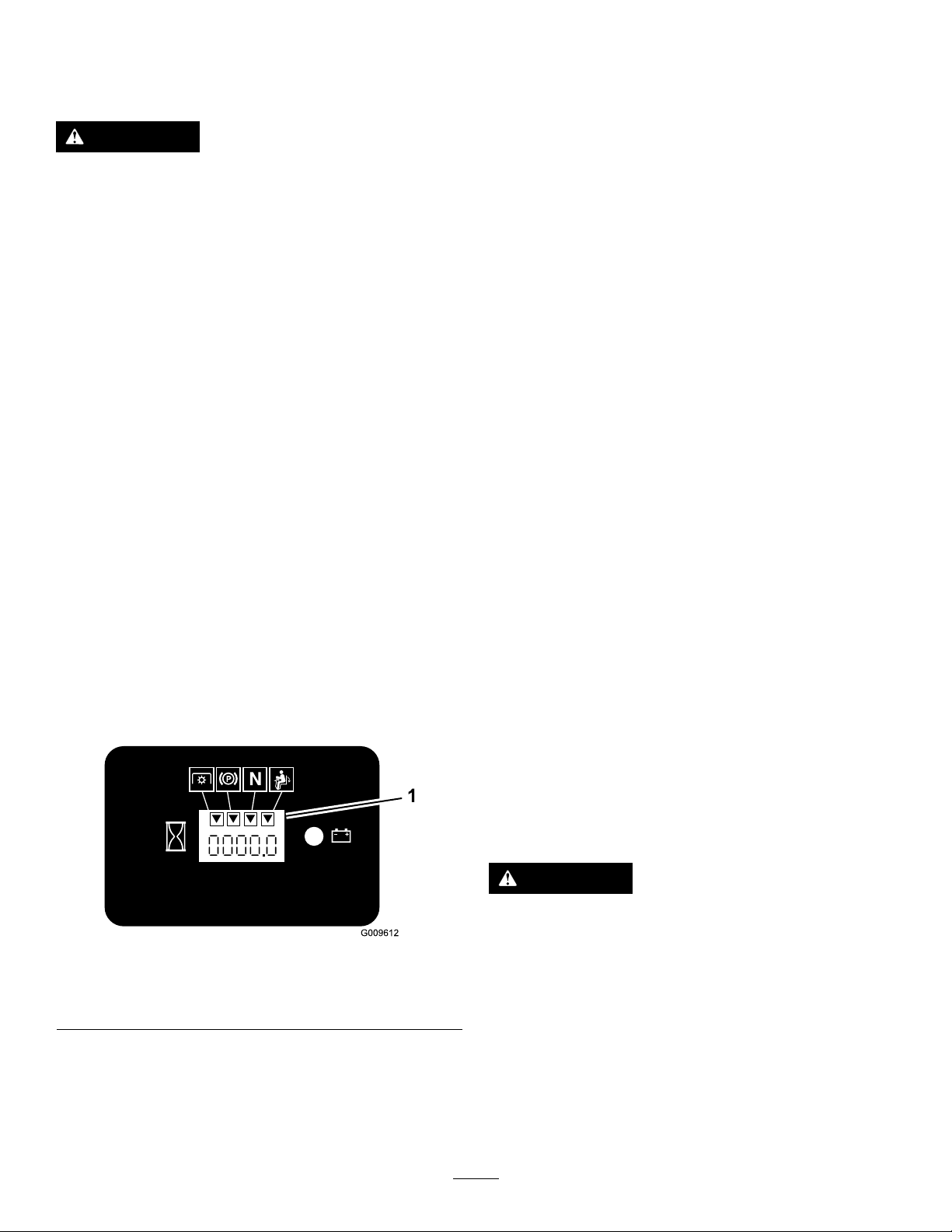
Thehourmeterhassymbolstonotifytheuserwhen
theinterlockcomponentisinthecorrectposition.
Whenthecomponentisinthecorrectposition,a
trianglelightsupinthecorrespondingsquare.
Figure16
1.Triangleslightupwhentheinterlockcomponentsareinthe
correctposition
5.Sittingontheseat,disengagetheparkingbrake,
movethePTOswitchtoOFFandmovethe
motion-controlleverstoNEUTRAL-LOCKposition.
Trystartingtheengine;theengineshouldnot
crank.
DrivingForwardor Backward
Thethrottlecontrolregulatestheenginespeedas
measuredinrpm(revolutionsperminute).Place
thethrottlecontrolintheFASTpositionforbest
performance.AlwaysoperateintheFULLTHROTTLE
positionwhenmowing.
CAUTION
Machinecanspinveryrapidly.Operatormay
g009612
losecontrolofmachineandcausepersonal
injuryordamagetomachine.
•Usecautionwhenmakingturns.
•Slowthemachinedownbeforemaking
sharpturns.
TestingtheSafety-Interlock System
ServiceInterval:Beforeeachuseordaily
DrivingForward
1.Releasetheparkingbrake;refertoAdjustingthe
ParkingBrake(page49).
22
Page 23

2.Movetheleverstothecenter,unlockedposition.
3.Togoforward,slowlypushthemotion-control
leversforward(Figure17).
Note:Theenginekillsifthetractioncontrol
leversaremovedwiththeparkingbrake
engaged.
Togostraight,applyequalpressuretoboth
motion-controllevers(Figure17).
Toturn,movethemotion-controllevertoward
neutralinthedirectionyouwanttoturn(Figure
17).
Thefartheryoumovethetractioncontrollevers
ineitherdirection,thefasterthemachinemoves
inthatdirection.
Tostop,pullthemotion-controlleverstothe
NEUTRALposition.
Togostraight,applyequalpressuretoboth
motion-controllevers(Figure17).
Toturn,releasepressureonthemotion-control
levertowardthedirectionyouwanttoturn
(Figure17).
Tostop,pushthemotion-controlleverstothe
NEUTRALposition.
Figure17
1.Motion-controlleverinthe
NEUTRAL-LOCKposition
2.Centerunlockposition5.Frontofthemachine
3.Forward
4.Backward
DrivingBackward
1.Movetheleverstothecenter,unlockedposition.
2.Togobackward,slowlypullthemotion-control
leversrearward(Figure17).
g004532
23
Page 24

StoppingtheMachine
AdjustingtheAnti-Scalp
Tostopthemachine,movethetraction-controllevers
totheNEUTRALpositionandthentotheLOCKED
position,disengagethepowertakeoff(PTO),andturn
theignitionkeytotheOFFposition.
Settheparkingbrakewhenyouleavethemachine.
Remembertoremovethekeyfromtheignitionswitch.
CAUTION
Childrenorbystandersmaybeinjuredifthey
moveorattempttooperatethemachinewhile
itisunattended.
Alwaysremovetheignitionkeyandsetthe
parkingbrakewhenleavingthemachine
unattended,evenifjustforafewminutes.
AdjustingtheHeight-of-Cut
Theheight-of-cutisadjustedfrom38to127mm
(1-1/2to5inches)in6mm(1/4inch)incrementsby
relocatingthepinintodifferentholelocations.
1.Raisetheheight-of-cutlevertotheTRANSPORT
position(alsothe127mm(5inch)cutting-height
position)(Figure18).
2.Toadjust,removethepinfromtheheight-of-cut
bracket(Figure18).
Rollers
Wheneveryouchangetheheight-of-cut,itis
recommendedtoadjusttheheightoftheanti-scalp
rollers.
1.DisengagethePTO,movethemotion-control
leverstotheNEUTRAL-LOCKposition,andsetthe
parkingbrake.
2.Shutofftheengine,removethekey,andwait
forallmovingpartstostopbeforeleavingthe
operatingposition.
3.Afteradjustingtheheightofcut,adjusttherollers
byremovingtheangenut,bushing,spacer,
andbolt(Figure19orFigure20).
Note:The2middlerollersdonothaveaspacer
(Figure19orFigure20).
4.Selectaholesotheanti-scalprollerispositioned
tothenearestcorrespondingheight-of-cut
desired.
5.Installtheangenutbushing,spacer,andbolt.
Torqueto54to61N∙m(40to45ft-lb)(Figure
19orFigure20).
6.Repeatthisadjustmentontheotheranti-scalp
rollers.
3.Selectaholeintheheight-of-cutbracket
correspondingtotheheight-of-cutdesiredand,
insertthepin(Figure18).
4.Movethelevertotheselectedheight.
Figure18
1.Height-of-cutlever
2.Pin
g009568
24
Page 25

Figure20
g005960
Figure19
1.Anti-scalproller4.Flangenut
2.Spacer
3.Bushing
5.Bolt
g005887
1.Anti-scalproller4.Flangenut
2.Spacer
3.Bushing
5.Bolt
PositioningtheSeat
Theseatcanmoveforwardandbackward.Position
theseatwhereyouhavethebestcontrolofthe
machineandaremostcomfortable.
Toadjust,movetheleversidewaystounlockseat
(Figure21).
g019754
Figure21
25
Page 26

ChangingtheSeat
PushingtheMachineby
Suspension
Theseatisadjustabletoprovideasmoothand
comfortableride.Positiontheseatwhereyouare
mostcomfortable.
Toadjustit,turntheknobinfronteitherdirectionto
providethebestcomfort(Figure22).
Figure22
1.Seatsuspensionknob
Hand
Important:Alwayspushthemachinebyhand.
Nevertowthemachinebecausehydraulicdamage
mayoccur.
PushingtheMachine
1.Disengagethepowertakeoff(PTO)andturn
theignitionkeytooff.Movetheleversto
NEUTRAL-LOCKposition,applytheparkingbrake,
andremovethekey.
2.Rotatethebypassvalvescounterclockwise1
turn.Thisallowshydraulicuidtobypassthe
pumpenablingthewheelstoturn(Figure24).
Important:Donotrotatethebypassvalves
morethan1turn.Thispreventsvalvesfrom
comingoutofthebodyandcausinguidto
runout.
g019768
3.Disengageparkingbrakebeforepushingthe
machine.
UnlatchingtheSeat
1.Movetheseattothemostrearwardposition.
Thispreventsinterferencewhentheseatis
raised.
2.Pushtheseatlatchrearwardtounlatchtheseat.
3.Raisetheseatup.Thisallowsaccesstothe
machineundertheseat(Figure23).
ChangingtoMachineOperation
Rotatethebypassvalvesclockwise1turntooperate
themachine(Figure24).
Note:Donotovertightentheby-passvalves.
Themachinewillnotdriveunlessbypassvalvesare
turnedin.
Figure23
1.Seatlatch3.Seat
2.Fuelcap
g000950
g010371
Figure24
1.Sideconsolecontrols
2.Bypassvalve
26
3.Hydraulicpumps
Page 27

OperatingwiththeOverheat Sensor
ThismachinehasasensorthatturnsOFFthemower
deckwhentheengineoverheats.Whentheengine
overheats,theaudiblealarmandlightalarmturnsON
alongwiththemowerdeckturningOFF.
IfthemowerdeckturnsOFFautomaticallybecause
ofoverheating,drivethemachinetoasafeareaand
toatruckortrailer.
1.Backthemachineupthe
ramp.
g028043
Figure25
2.Drivethemachineforward
downtheramp.
Ifthemachineoverheats,ensurethattheareaaround
theengineandradiatorisclearofanydebris.Turnthe
engineoffandallowittocooldownbeforeyouengage
themowerdeck.Iftheenginecontinuestooverheat,
takeyourmachinetoanAuthorizedServiceDealer.
TransportingtheMachine
Useaheavy-dutytrailerortrucktotransportthe
machine.Ensurethatthetrailerortruckhasall
necessarylightingandmarkingasrequiredbylaw.
Pleasecarefullyreadallthesafetyinstructions.
Knowingthisinformationcouldhelpyou,yourfamily,
petsorbystandersavoidinjury.
Totransportthemachine:
•Lockthebrakeandblockthewheels.
•Securelyfastenthemachinetothetrailerortruck
withstraps,chains,cable,orropes.
•Secureatrailertothetowingvehiclewithsafety
chains.
Important:Donotusenarrowindividualramps
foreachsideofthemachine.
WARNING
Drivingonthestreetorroadwaywithout
turnsignals,lights,reectivemarkings,
oraslowmovingvehicleemblemis
dangerousandcanleadtoaccidents
causingpersonalinjury.
Donotdrivemachineonapublicstreetor
roadway.
LoadingtheMachine
Useextremecautionwhenloadingortheunloading
machineontoatraileroratruck.Useafull-widthramp
thatiswiderthanthemachineforthisprocedure.
Backthemachineuptherampanddriveitforward
downtheramp(Figure25).
27
Page 28

Ensurethattherampislongenoughsothattheangle
withthegrounddoesnotexceed15degrees(Figure
26).Onatground,thisrequiresaramptobeatleast
4timesaslongastheheightofthetrailerortruckbed
totheground.Asteeperanglemaycausemower
componentstogetcaughtasthemachinemovesfrom
theramptothetrailerortruck.Steeperanglesmay
alsocausethemachinetotiporlosecontrol.Ifyou
areloadingthemachineonornearaslope,position
thetrailerortrucksothatitisonthedownsideof
theslopeandtherampextendsuptheslope.This
minimizestherampangle.
WARNING
Loadingamachineontoatrailerortruck
increasesthepossibilityoftip-overandcould
causeseriousinjuryordeath.
•Useextremecautionwhenoperatinga
machineonaramp.
•EnsurethattheROPSisintheupposition
andusetheseatbeltwhenloadingor
unloadingthemachine.Ensurethatthe
ROPSclearsthetopofanenclosedtrailer.
•Useonlyafull-widthramp;donotuse
individualrampsforeachsideofthe
machine.
•Donotexceeda15-degreeanglebetween
therampandthegroundorbetweenthe
rampandthetrailerortruck.
•Ensurethatthelengthoframpisatleast4
timesaslongastheheightofthetraileror
truckbedtotheground.Thisensuresthat
rampangledoesnotexceed15degreeson
atground.
•Backuprampsanddriveforwarddown
ramps.
•Avoidsuddenaccelerationordeceleration
whiledrivingthemachineonarampas
thiscouldcausealossofcontrolora
tip-oversituation.
1.Full-widthrampinstowed
position
2.Sideviewoffull-width
rampinloadingposition
3.Notgreaterthan
15degrees
g027996
Figure26
4.Rampisatleast4times
aslongastheheightof
thetrailerortruckbedto
theground
5.H=heightofthetraileror
truckbedtotheground
6.Trailer
28
Page 29

UsingtheZStand™
TheZStandraisesthefrontendofthemachineto
allowyoutocleanthemowerandremovetheblades.
WARNING
Themachinecouldfallontosomeoneand
causeseriousinjuryordeath.
•Useextremecautionwhenoperatingthe
machineontheZStand™.
•Useonlyforcleaningthemowerand
removingtheblades.
•DonotkeepthemachineontheZStand™
forextendedperiodsoftime.
•Alwaysturntheengineoff,setthe
parkingbrake,andremovethekeybefore
performinganymaintenancetothemower.
Figure28
1.ZStand(positionedinslot)
2.Crackinsidewalkorturf
4.Setthefootofstandonthegroundandrestthe
latchonthepivottab(Figure28).
5.Starttheengineandputitathalfthrottle.
3.Latchrestingonpivottab
Note:Forbestresults,placethefootofstand
intoseamsinsidewalksorintotheturf(Figure
28).
g001812
DrivingupontotheZStand™
Important:UsetheZStand™onalevelsurface.
1.RaisethemowertotheTRANSPORTposition.
2.Removethebracketpin(Figure27).
Figure27
1.ZStand™
2.Latch
3.Bracket
4.Bracketpin
5.Bottomofslot
6.Driveontothestand.Stopwhenthelatchdrops
overthetabintotheLOCKEDposition(Figure
28).Onceontothestand,engagetheparking
brakeandturnofftheengine.
7.Chockorblockthedrivewheels.
WARNING
Theparkingbrakemaynotholdmachine
parkedonZStand™andcouldcause
personalinjuryorpropertydamage.
DonotparkonZStand™unlesswheels
arechockedorblocked.
8.Performthemaintenance.
g001811
DrivingofftheZStand™
1.Removethechocksorblocks.
2.RaisethelatchtotheUNLOCKEDposition(Figure
29).
3.Raisethelatch.Swingthestandfootoutfront
andslidestandtowardmachine,intothebottom
ofslot(Figure27andFigure28).
29
Page 30

MowingatCorrectIntervals
Normally,mowevery4days.However,grassgrows
atdifferentratesatdifferenttimes.T omaintainthe
samecuttingheight,whichisagoodpractice,mow
moreofteninearlyspring.Asthegrassgrowthrate
slowsinmid-summer,mowlessfrequently .Ifyou
cannotmowforanextendedperiod,rstmowata
highcuttingheight;thenmowagain2dayslaterata
lowerheightsetting.
Figure29
1.ZStand™
2.Latch4.UNLOCKEDposition
3.Starttheengineandplaceitathalfthrottle.
Disengagetheparkingbrake.
4.Slowlydrivebackwardoffthestand.
5.ReturnthestandtoitsRESTposition(Figure27).
3.LOCKEDposition
OperatingTips
UsingtheFastThrottleSetting
Forbestmowingandmaximumaircirculation,operate
theengineattheFASTthrottleposition.Airisrequired
tothoroughlycutgrassclippings,sodonotsetthe
heightofcutsolowastototallysurroundthemower
inuncutgrass.Alwaystrytohave1sideofthemower
freefromuncutgrass,whichallowsairtobedrawn
intothemower.
CuttingaLawnfortheFirstTime
g001813
AdjustingtheCuttingSpeed
Toimprovecutquality,useaslowergroundspeed
incertainconditions.
AvoidingCuttingTooLow
Ifthecuttingwidthofthemoweriswiderthanthe
moweryoupreviouslyused,raisethecuttingheightto
ensurethatuneventurfisnotcuttooshort.
CuttingLongGrass
Ifthegrassiseverallowedtogrowslightlylongerthan
normal,orifitcontainsahighdegreeofmoisture,
raisethecuttingheighthigherthanusualandcutthe
grassatthissetting.Thencutthegrassagainusing
thelower,normalsetting.
Stopping
Ifyoumuststoptheforwardmotionofthemachine
whilemowing,aclumpofgrassclippingsmaydrop
ontoyourlawn.Toavoidthis,moveontoapreviously
cutareawiththebladesengaged.
Cutthegrassslightlylongerthannormaltoensure
thatthecuttingheightofthemowerdoesnotscalp
anyunevenground.However,thecuttingheightyou
haveusedinthepastisgenerallythebesttouse.
Whencuttinggrasslongerthan15.24cm(6inches)
tall,youmaywanttocutthelawntwicetoensurean
acceptablequalityofcut.
CuttingaThirdoftheGrassBlade
Itisbesttocutonlyaboutathirdofthegrassblade.
Cuttingmorethanthatisnotrecommendedunless
grassissparse,oritislatefallwhengrassgrows
moreslowly.
AlternatingtheMowingDirection
Alternatethemowingdirectiontokeepthegrass
standingstraight.Thisalsohelpsdisperseclippings,
whichenhancesdecompositionandfertilization.
KeepingtheUndersideofthe
MowerClean
Cleanclippingsanddirtfromtheundersideofthe
moweraftereachuse.Ifgrassanddirtbuildupinside
themower,cuttingqualitywilleventuallybecome
unsatisfactory.
MaintainingtheBlades
Maintainasharpbladethroughoutthecuttingseason
becauseasharpbladecutscleanlywithouttearingor
shreddingthegrassblades.T earingandshredding
turnsgrassbrownattheedges,whichslowsgrowth
andincreasesthechanceofdisease.Checkthe
cutterbladesdailyforsharpness,andforanywearor
damage.Filedownanynicksandsharpentheblades
asnecessary.Ifabladeisdamagedorworn,replace
itimmediatelywithagenuineT ororeplacementblade.
30
Page 31

Maintenance
RecommendedMaintenanceSchedule(s)
MaintenanceService
Interval
Aftertherst8hours
Aftertherst25hours
Aftertherst50hours
Aftertherst100hours
Beforeeachuseordaily
Every25hours
MaintenanceProcedure
•Checktheenginecoolantlevel.
•Checkthehydraulicuid.
•Changethehydrauliclter.
•Changetheengineoil.
•Changetheengine-oillter.
•Checkthetorqueonthewheellugnuts.
•Checkthewheel-hubslottednut.
•Checkthewheellugnuts.
•Changethegearboxoil.
•Checkthesafetysystem.
•Checktheengineoil.
•Checktheenginecoolantlevel.
•Cleantheengineoilcooler.
•Checkthemowerblades.
•Cleanthemowerdeck.
•Greasethemowerdeckandspindles.
•Greasethepumpbeltidlerarm.
•Greasethedrivebeltidlerarm.
•Greasethebrakelever .
•Checkthehydraulicuid.
Every40hours
Every50hours
Every100hours
Every150hours
Every200hours
Every250hours
Every400hours
Every500hours
•Drainthewaterseparator.
•Checkthetirepressure.
•CheckthePTOdrivebelt.
•Checkthepumpdrivebelt.
•Checkthealternatorbelt.
•Changetheengineoil.
•Checkthegearbox-oillevel.
•Checktheenginecoolingsystemhoses.
•Inspectthebeltsforcracksandwear.
•Checkthehydraulichoses.
•Lubricatethemachinewithlightoil.
•Changetheengine-oillter.
•Greasethebrakepivot.
•Checkand/orreplacetheairlter(moreoftenindirtyordustyconditions).
•ChangethehydrauliclterandhydraulicoilwhenusingMobil®1oil.
•Replacethefuellter(moreoftenindirtyordustyconditions).
•Checkthetorqueonthewheellugnuts.
•Checkthewheel-hubslottednut.
•Checkthewheellugnuts.
•Adjustthecasterpivotbearing(oryearly,whichevercomesrst).
•Adjusttheelectricclutch.
•ChangethehydrauliclterandhydraulicoilwhenusingT oro®HYPR-OIL™500
hydraulicoil.
•Greasethefrontcasterpivots(moreoftenindirtyordustyconditions).
Yearly
•Changethegearboxoil.
•Changetheenginecoolant.
31
Page 32

Important:Refertoyourengineowner’smanualforadditionalmaintenanceprocedures.
CAUTION
Ifyouleavethekeyintheignitionswitch,someonecouldaccidentlystarttheengineand
seriouslyinjureyouorotherbystanders.
Removethekeyfromtheignitionanddisconnectthewirefromthesparkplug(s)beforeyoudo
anymaintenance.Setthewireasidesothatitdoesnotaccidentallycontactthesparkplug.
Pre-Maintenance
Procedures
ReleasingtheMower-Deck Curtain
Loosenthebottomboltofthecurtaintoreleasethe
mower-deckcurtainandaccessthetopofthemower
deck(Figure30).Tightentheboltaftermaintenance
toinstallthecurtain.
RemovingtheSheet-Metal Guard
Loosenthe2frontboltsandremovethesheet-metal
guardtoaccessthemowerbeltsandspindles(Figure
31).Placethesheet-metalguardandtightenthebolts
aftermaintenance.
g027946
Figure31
g027945
Figure30
1.Bolt
2.Curtain
1.Sheet-metalguard
2.Bolt
32
Page 33

Lubrication
LubricatethemachinewhenshownontheCheck
ServiceReferenceAiddecal(Figure32).Grease
morefrequentlywhenoperatingconditionsare
extremelydustyorsandy.
GreaseType:General-purposegrease.
GreasingtheMachine
1.DisengagethePTO,movethemotion-control
leverstotheNEUTRAL-LOCKposition,andsetthe
parkingbrake.
2.Shutofftheengine,removethekey,andwait
forallmovingpartstostopbeforeleavingthe
operatingposition.
3.Cleanthegreasettingswitharag.Makesure
toscrapeanypaintoffthefrontofthetting(s).
4.Connectagreaseguntothetting.Pump
greaseintothettingsuntilgreasebeginsto
oozeoutofthebearings.
5.Wipeupanyexcessgrease.
g005930
Figure32
GreasingtheFrontCaster Pivots
Lubricatethefrontcasterpivotsonceayear.
1.Removethedustcapandadjustthecaster
pivots.Keepthedustcapoffuntilgreasing
isdone.RefertoAdjustingtheCaster-Pivot
Bearing(page45).
2.Removethehexplug.Threadagreasetting
intothehole.
3.Pumpgreaseintothettinguntilitoozesout
aroundthetopbearing.
4.Removethegreasettinginthehole.Installthe
hexplugandcap.
AddingGrease
LubricatethegreasettingsasshownontheCheck
ServiceReferenceAiddecal(Figure32).
AddingLightOilorSpray Lubrication
ServiceInterval:Every150hours
Lubricatethemachineinthefollowingareaswith
spraytypelubricantorlightoil.
•Seatswitchactuator.
•Brakehandlepivot.
•Brakerodbushings.
•Motioncontrolbronzebushings.
GreasingtheMowerDeck andBeltIdlers
ServiceInterval:Every25hours—Greasethemower
deckandspindles.
Every25hours—Greasethepumpbeltidler
arm.
Every25hours—Greasethedrivebeltidlerarm.
GreasewithNo.2lithiumormolybdenumgrease.
Important:Makesurecuttingunitspindlesare
fullofgreaseweekly.
1.DisengagethePTO,movethemotion-control
leverstotheNEUTRAL-LOCKposition,andsetthe
parkingbrake.
33
Page 34

2.Shutofftheengine,removethekey,andwait
forallmovingpartstostopbeforeleavingthe
operatingposition.
3.Loosenthebottomboltholdingthemower-deck
curtaintothemowerdeck.RefertoReleasing
theMower-DeckCurtain(page32).
4.Removethesheetmetalguard.Referto
RemovingtheSheet-MetalGuard(page32)
5.Removethebeltcoversandtheboltsattached
tothem.
6.Greasethe3spindlebearingsuntilgrease
comesout(Figure33).
7.Greasethettingsonthepusharms(Figure33).
12.Tightentheboltforthemower-deckcurtain.
RefertoReleasingtheMower-DeckCurtain
(page32).
Figure33
8.GreasethePTOdrivebeltidlerarm(Figure34).
9.Greasethepumpbeltidlerarm(Figure34).
Figure34
g012504
g007170
10.Installthebeltcovers.
11.Installthesheetmetalguard.RefertoRemoving
theSheet-MetalGuard(page32).
34
Page 35

EngineMaintenance
ServicingtheAirCleaner
Note:Checktheltersmorefrequentlyifoperating
conditionsareextremelydustyorsandy.
RemovingtheAirFilter
ServiceInterval:Every250hours(moreoftenindirty
ordustyconditions).
1.DisengagethePTO,movethemotion-control
leverstotheNEUTRAL-LOCKposition,andsetthe
parkingbrake.
2.Shutofftheengine,removethekey,andwait
forallmovingpartstostopbeforeleavingthe
operatingposition.
3.Releasethelatchesontheaircleanerandpull
theair-cleanercoverofftheair-cleanerbody
(Figure35).
4.Cleantheinsideoftheair-cleanercoverwith
compressedair.
5.Gentlyslidethelteroutoftheair-cleanerbody
(Figure35).Avoidknockingthelterintothe
sideofthebody.
6.Inspectthelterfordamagebylookingintothe
lterwhileshiningabrightlightontheoutside
ofthelter.Holesinthelterappearasbright
spots.Ifthelterisdamageddiscardit.
Figure35
1.Air-lterbody
2.Airlter
3.Air-cleanercover
4.Latches
InstallingtheAirFilter
1.Ifinstallinganewlter,checkthelterfor
shippingdamage.Donotuseadamagedlter.
2.Carefullyslidethelterintothelterbody(Figure
36).Ensurethatitisfullyseatedbypushingon
theouterrimofthelterwhileinstallingit.
Important:Donotpressonthesoftinside
areaofthelter.
3.Installtheair-cleanercoverandsecurethe
latches(Figure36).
g001049
35
Page 36

ServicingtheEngineOil
OilType:High-qualitydetergentoilclassiedAPI
ServiceCDorhigherfordieselengines.Donotuse
specialadditiveswithrecommendedoils.
CrankcaseCapacity:3.7L(3.9USqt)
Viscosity:Seethetablebelow:
1.Air-lterbody
2.Airlter
Figure36
3.Air-cleanercover
4.Latches
g001048
Figure37
g001061
PreparingtoServicetheEngine Oil
Important:Thefastenersforthefrontengine
panelaredesignedtoremainonthemachineafter
coverremoval.Loosenallofthefastenersafew
turnssothatthepanelisloosebutstillattached,
thengobackandloosenthemuntilthepanel
comesfree.Thispreventsyoufromaccidentally
strippingtheboltsfreeoftheretainers.
Tilttheseatforward,loosentheboltsholdingthefront
enginepanelandremoveit(Figure38).
36
Page 37

Figure38
1.Bolt2.Frontenginepanel
Note:Afterservicingtheengineoil,installtheengine
panelandtilttheseatintoitsuprightposition.
CheckingtheEngine-OilLevel
ServiceInterval:Beforeeachuseordaily
Note:Checktheoilwhentheengineiscold.
1.DisengagethePTO,movethemotion-control
leverstotheNEUTRAL-LOCKposition,andsetthe
parkingbrake.
g032601
g012347
g032641
Figure39
2.Shutofftheengine,removethekey,andwait
forallmovingpartstostopbeforeleavingthe
operatingposition.
3.Checktheengine-oillevel(Figure39).
4.Starttheengine,runitatidlefor5minutes,
shutofftheengine,waitfor3minutes,andthen
checktheengine-oillevel.Ifneeded,addoilup
totheFULLmarkonthedipstick.
Important:Besuretokeeptheengine-oillevel
betweentheupperandlowerlimitsontheoil
gauge.Enginefailuremayoccurasaresultof
overllingorunderllingtheengineoil.
Important:Addtheoilveryslowlyanddonot
blocktheopeningofthellerhole(Figure40).If
youaddoiltoofastorblockthehole,theoilcould
backupandfoultheairintakes,causingengine
damage.
37
Page 38

Figure40
1.Notetheclearanceleftinthelleropening.
DrainingtheEngineOil
ServiceInterval:Aftertherst50hours
Every100hours
1.Starttheengineandletitrunfor5minutes.
Note:Thiswarmstheoilsoitdrainsbetter.
2.Parkthemachineonalevelsurface,disengage
thePTO,movethemotion-controlleverstothe
g000955
NEUTRAL-LOCKposition,andsettheparking
brake.
3.Shutofftheengine,removethekey,andwait
forallmovingpartstostopbeforeleavingthe
operatingposition.
38
Page 39

ChangingtheEngine-OilFilter
ServiceInterval:Aftertherst50hours
Every200hours
1.Draintheoilfromtheengine;refertoDraining
theEngineOil(page38).
2.Changetheengine-oillter(Figure42).
g032646
g032649
Figure41
Note:Disposeoftheusedoilatarecyclingcenter.
g032642
g032644
Figure42
3.Addoil;refertoCheckingtheEngine-OilLevel
(page37).
39
Page 40

FuelSystem
Maintenance
ServicingtheFuelFilter andWaterSeparator
DrainingtheWaterSeparator
ServiceInterval:Every40hours
1.Positionthemachineonalevelsurface.
2.DisengagethePTO,movethemotion-control
leverstotheNEUTRAL-LOCKposition,andsetthe
parkingbrake.
3.Shutofftheengine,removethekey,andwait
forallmovingpartstostopbeforeleavingthe
operatingposition.
4.Locatethewaterseparatoratthebackleftof
themachine.
5.Placeadrainpanbelowthewaterseparator.
6.Openthedrainvalveonthewaterseparator
approximately1turntoallowwaterandother
contaminatestodrain(Figure43).
7.Closethedrainvalvewhenonlydieselfuel
comesout(Figure43).
1.Allowthemachinetocooldown.
2.DisengagethePTO,movethemotion-control
leverstotheNEUTRAL-LOCKposition,andsetthe
parkingbrake.
3.Shutofftheengine,removethekey,andwait
forallmovingpartstostopbeforeleavingthe
operatingposition.
4.Closethefuel-shutoffvalve(Figure44).
5.Loosenthe2hoseclampsanddisconnectthe
fuellinesfromthefuellter(Figure44).
6.Installanewlter.Connectthefuellinestothe
fuellterandinstallthe2hoseclamps(Figure
44).
7.Openthefuel-shutoffvalve.
8.Starttheengineandcheckforleaks.
Figure43
1.Drainvalve
2.Waterseparator
3.Backofmachine
ChangingtheFuelFilter
ServiceInterval:Every400hours/Yearly(whichever
comesrst)(moreoftenindirtyor
dustyconditions).
Neverinstalladirtyfuellterifitisremovedfromthe
fuelline.
g007169
g007697
Figure44
1.Fuellter4.Leftsideofthemachine
2.Hoseclamp
3.Fuelpump
5.Fuel-shutoffvalve
ServicingtheFuelTank
Donotattempttodrainthefueltank.Ensurethatan
AuthorizedServiceDealerdrainsthefueltankand
servicesanycomponentsofthefuelsystem.
40
Page 41
ElectricalSystem
Maintenance
ServicingtheBattery
WARNING
Incorrectbatterycableroutingcoulddamage
themachineandcablescausingsparks.
Sparkscancausethebatterygassesto
explode,resultinginpersonalinjury.
•Alwaysdisconnectthenegative(black)
batterycablebeforedisconnectingthe
WARNING
positive(red)cable.
CALIFORNIA
Proposition65Warning
Batteryposts,terminals,andrelated
accessoriescontainleadandlead
compounds,chemicalsknownto
theStateofCaliforniatocause
cancerandreproductiveharm.Wash
handsafterhandling.
DANGER
Batteryelectrolytecontainssulfuricacid
whichisadeadlypoisonandcausessevere
burns.
Donotdrinkelectrolyteandavoidcontact
withskin,eyesorclothing.Wearsafety
glassestoshieldyoureyesandrubbergloves
toprotectyourhands.
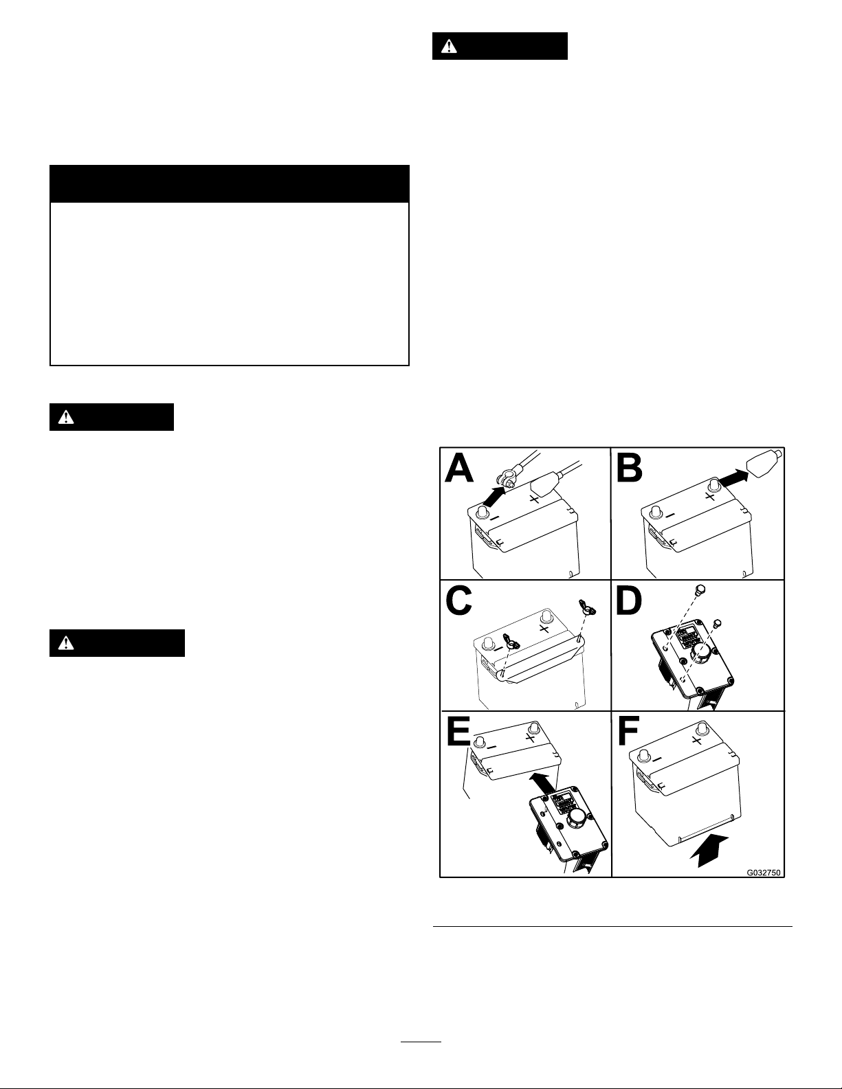
RemovingtheBattery
•Alwaysconnectthepositive(red)battery
cablebeforeconnectingthenegative
(black)cable.
1.DisengagethePTO,movethemotion-control
leverstotheNEUTRAL-LOCKposition,andsetthe
parkingbrake.
2.Shutofftheengine,removethekey,andwait
forallmovingpartstostopbeforeleavingthe
operatingposition.
3.Unlatchtheseatandtilttheseatup.
4.RemovethebatteryasshowninFigure49
WARNING
Batteryterminalsormetaltoolscouldshort
againstmetalmachinecomponentscausing
sparks.Sparkscancausethebatterygasses
toexplode,resultinginpersonalinjury.
•Whenremovingorinstallingthebattery ,
donotallowthebatteryterminalstotouch
anymetalpartsofthemachine.
•Donotallowmetaltoolstoshortbetween
thebatteryterminalsandmetalpartsofthe
machine.
g032750
Figure45
41
Page 42

InstallingtheBattery
ChargingtheBattery
Note:Positionthebatteryinthetraywiththeterminal
postsoppositefromthehydraulictank.
WARNING
Chargingthebatteryproducesgassesthat
canexplode.
Neversmokenearthebatteryandkeepsparks
andamesawayfrombattery.
Important:Alwayskeepthebatteryfullycharged
(1.265specicgravity).Thisisespecially
importanttopreventbatterydamagewhenthe
temperatureisbelow0°C(32°F).
1.Makesurethellercapsareinstalledinbattery .
Chargebatteryfor10to15minutesat25to30A
or30minutesat10A.
2.Whenthebatteryisfullycharged,unplug
thechargerfromtheelectricaloutlet,then
disconnectthechargerleadsfromthebattery
posts(Figure47).
3.Installthebatteryinthemachineandconnect
thebatterycables,refertoInstallingtheBattery
(page42).
Figure46
g032751
g000960
Figure47
1.Positivebatterypost
2.Negativebatterypost
3.Red(+)chargerlead
4.Black(-)chargerlead
42
Page 43

ServicingtheFuses
DriveSystem
Theelectricalsystemisprotectedbyfuses.Itrequires
nomaintenance,however,ifafuseblowscheck
component/circuitformalfunctionorshort.
1.Unlatchtheenginehoodandraisetheengine
hoodtogainaccesstofuseholder(Figure48).
2.T oreplacethefuses,pulloutonthefuseto
removeit.
3.Installanewfuse(Figure48).
Maintenance
AdjustingtheTracking
Themachinehasaknobforadjustingthetracking
locatedundertheseat.
Important:Adjustthehandleneutraland
hydraulicpumpneutralbeforeadjustingthe
tracking.RefertoAdjustingtheControlHandle
NeutralPosition(page52)andSettingthe
HydraulicPumpNeutralPosition(page55).
1.Pushbothcontrolleversforwardthesame
distance.
2.Checkifthemachinepullsto1side.Ifitdoes,
stopthemachineandsettheparkingbrake.
3.Unlatchtheseatandtilttheseatforwardto
accessthetrackingknob.
Note:Determinetheleftandrightsidesofthe
machinefromthenormaloperatingposition.
4.T omakethemachinegoright,turntheknob
towardtherightsideofthemachine.Referto
Figure49.
Figure48
1.Ignition—30A(F1)3.Clutch—10A(F3)
2.Radiatorfan—50A(large,
heavydutyfuse)
4.Leftfueltank
5.T omakethemachinegoleft,turntheknob
towardtheleftsideofthemachine.Referto
g012492
Figure49.
6.Repeatadjustmentuntilthetrackingiscorrect.
43
Page 44

Figure49
1.Trackingknob4.Turnthiswaytotrackright.
2.Hydraulictank
3.Hydraulicpumps
5.Turnthiswaytotrackleft.
CheckingtheWheelLug Nuts
Checkandtorquethewheellugnutsto122to129
N∙m(90to95ft-lb).
CheckingtheWheel-Hub SlottedNut
ServiceInterval:Aftertherst100hours—Checkthe
wheel-hubslottednut.
Every500hours—Checkthewheel-hubslotted
nut.
Aftertherst100hours—Checkthewheellug
nuts.
Every500hours—Checkthewheellugnuts.
Theslottednutneedstobetorquedto170N∙m(125
ft-lb).
1.DisengagethePTO,movethemotion-control
g001070
leverstotheNEUTRAL-LOCKposition,andsetthe
parkingbrake.
2.Shutofftheengine,removethekey,andwait
forallmovingpartstostopbeforeleavingthe
operatingposition.
3.Removethecotterpin.
4.T orquetheslottednutto170N∙m(125ft-lb)
(Figure51).
CheckingtheTirePressure
ServiceInterval:Every50hours/Monthly(whichever
comesrst)
Maintaintheairpressureinthereartiresat90kPa
(13psi).Uneventirepressurecancauseunevencut.
Checkthetireswhentheyarecoldtogetthemost
accuratepressurereading.
Note:Thefronttiresaresemi-pneumatictiresanddo
notrequireairpressuremaintenance.
Figure50
g001051
Figure51
1.Slottednut3.Holeinthreadedshaft
2.2threadsorlessshowing
5.Checkthedistancefrombottomofslotinnut
toinsideedgeofhole.2threadsorlessshould
beshowing(Figure51).
6.Ifmorethan2threadsareshowingremovenut
andinstallwasherbetweenhubandnut.
7.T orquetheslottednutto170N∙m(125ft-lb)
(Figure51).
g001055
8.Tightenthenutuntilthenextsetofslotslineup
withtheholeintheshaft(Figure51).
9.Replacethecotterpin.
4.Washer(ifneeded)
44
Page 45

AdjustingtheCaster-Pivot Bearing
ServiceInterval:Every500hours(oryearly,which
evercomesrst).
1.DisengagethePTO,movethemotion-control
leverstotheNEUTRAL-LOCKposition,andsetthe
parkingbrake.
2.Shutofftheengine,removethekey,andwait
forallmovingpartstostopbeforeleavingthe
operatingposition.
3.Removethedustcapfromcasterandtighten
thelocknut(Figure52).
4.Tightenthelocknutuntilthespringwashersare
atandthenbackoffa1/4turntoproperlyset
thepre-loadonthebearings(Figure52).
Important:Makesurespringwashersare
installedcorrectlyasshowninFigure52.
5.Installthedustcap(Figure52).
3.Shutofftheengine,removethekey,andwait
forallmovingpartstostopbeforeleavingthe
operatingposition.
4.Removethesideorrearplugonthegearbox
(Figure53).
5.Theoilshouldbeuptotheopeningofthe
gearbox.
6.Addoilifneededtobringittothecorrectlevel.
Figure52
1.Springwashers
2.Locknut
3.Dustcap
ServicingtheGearbox
CheckingtheGearbox-OilLevel
ServiceInterval:Every100hours
UseSAE75W–90SyntheticGearLube.
1.Parkthemachineonalevelsurface.
2.DisengagethePTO,movethemotion-control
leverstotheNEUTRAL-LOCKposition,andsetthe
parkingbrake.
g001156
Figure53
1.Gearbox
2.Sideplug
g001297
ChangingtheGearboxOil
ServiceInterval:Aftertherst100hours
Yearly
ContactanAuthorizedServiceDealertochangethe
gearboxoil.
3.Rearplug
4.Pulley
AdjustingtheElectric Clutch
ServiceInterval:Every500hours
Theclutchisadjustabletoensureproperengagement
andproperbraking.
1.DisengagethePTO,movethemotion-control
leverstotheNEUTRAL-LOCKposition,andsetthe
parkingbrake.
45
Page 46
2.Shutofftheengine,removethekey,andwait
forallmovingpartstostopbeforeleavingthe
operatingposition.
3.Unlatchtheseatandtipitforward.
4.Loosenthefrontenginepanelknobsand
removethepanel.
5.Pulluponthespringloadedidlerpulleyforthe
PTOdrivebeltandremovethebeltfromthe
clutchpulley(Figure54).
Figure54
1.Spring-loadedidlerpulley3.PTOdrivebelt
2.Clutch4.Gearbox
6.Unplugtheelectricconnectionfortheclutch
(Figure55).
7.Removetheboltsholdingtherubberclutchstrap
tothemowerframe(Figure55).
g008212
Figure55
1.Clutch4.Clutchcenterbolt
2.Bolts(2)andnutsfor
clutchstrap
3.Rubberclutchstrap
5.Electricalconnection
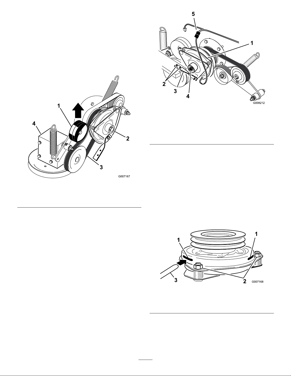
9.Inserta0.381to0.533mm(0.015to0.021inch)
feelergaugethrough1inspectionslotintheside
oftheassembly.Makesureitisbetweenthe
armatureandtherotorfrictionsurfaces(Figure
56).
g007167
10.Tightenthelocknutsuntilthereisslightbinding
onthefeelergaugebutitcanbemovedeasily
withintheairgap(Figure56).
11.Repeatthisfortheremainingslots.
12.Checkeachslotagainandmakeslight
adjustmentsuntilthefeelergaugebetween
therotorandarmaturehasveryslightcontact
betweenthem.
8.Removethecenterboltholdingtheclutchto
theengineshaftandremovetheclutchandkey
(Figure55).
Figure56
1.Slot
2.Adjustingnut
3.Feelergauge
13.Installtheclutchtotheengineshaftwiththekey.
14.Applythread-lockingadhesivetothecenterbolt.
15.Whileholdingthecrankshaftatthebackofthe
machine,installthecenterboltandtorqueitto
68N∙m(50ft-lb)(Figure55).
46
g007168
Page 47

16.Installtherubberclutchstraptothemower
framewiththe2previouslyremovedboltsand
nuts(Figure55).
17.PulluponthespringloadedidlerforthePTO
drivebeltandinstallitontotheclutchpulley
(Figure54).
CoolingSystem
Maintenance
ServicingtheCooling
18.Plugintheelectricconnectionfortheclutch
(Figure55).
19.Installthefrontenginepanelandtightenthe
knobs.
20.Lowerdowntheseat.
System
DANGER
Dischargeofhotpressurizedcoolantor
touchinghotradiatorandsurroundingparts
cancausesevereburns.
•Donotremovetheradiatorcapwhenthe
engineishot.Alwaysallowtheengineto
coolatleast15minutesoruntiltheradiator
capiscoolenoughtotouchwithout
burningyourhandbeforeremovingthe
radiatorcap.
•Donottouchradiatorandsurrounding
partsthatarehot.
DANGER
Rotatingshaftandfancancausepersonal
injury.
•Donotoperatethemachinewithoutthe
coversinplace.
•Keepngers,handsandclothingclearof
rotatingfananddriveshaft.
•Shutofftheengineandremovetheignition
keybeforeperformingmaintenance.
CAUTION
Swallowingenginecoolantcancause
poisoning.
•Donotswallowenginecoolant.
•Keepoutofreachfromchildrenandpets.
CheckingtheEngineCoolant Level
ServiceInterval:Beforeeachuseordaily
Aftertherst8hours
Every100hours
FluidType:50/50mixofextendedlifeantifreezeand
water
CoolingSystemCapacity:4.6L(176oz)
Note:Donotopentheradiatorcap.Doingthismay
induceairintothecoolingsystem.
47
Page 48

1.Positionthemachineonalevelsurface,shutoff
theengine,andsettheparkingbrake.
2.Unlatchtheseatandtilttheseatup.
3.Withtheenginecool,checktheoverowbottle
level.Theuidneedstobeuptothebumpon
theoutsideoftheoverowbottle(Figure57).
4.Ifthecoolantlevelislow,adda50/50mix
ofextendedlifeantifreezeandwatertothe
overowbottle(Figure57).
5.Addthe50/50coolantmixtotheoverowbottle
andllittotheindicatorlineonthebottle(Figure
57).
g001104
Figure58
1.Hydraulicoilcooler3.Radiatorscreen
2.Leftreartire
Figure57
1.Antifreezeoverowbottle2.Indicatorlineonsideof
overowbottle
CleaningtheEngine-OilCooler andRadiatorScreen
ServiceInterval:Beforeeachuseordaily
Beforeeachuse,checkandcleantheradiatorscreen
andoilcooler.Removeanybuild-upofgrass,dirtor
otherdebrisfromtheoilcoolerandradiatorscreen
withcompressedair(Figure58).
ChangingtheEngineCoolant
ServiceInterval:Yearly
HaveanAuthorizedServiceDealerchangetheengine
coolanteveryyear.
g001103
48
Page 49

BrakeMaintenance
BeltMaintenance
AdjustingtheParking Brake
ServiceInterval:Every25hours
Every200hours
1.Engagetheparkingbrake.
2.Measurethelengthofthespring.Measurement
shouldbe64mm(2-1/2inches)betweenthe
washers(Figure59).
3.Ifadjustmentisnecessary,releasetheparking
brake,loosenthejamnutbelowthespringand
adjustthenutdirectlybelowthespring(Figure
59).Turnthenutuntilthecorrectmeasurement
isobtained.Turnthenutclockwisetoshorten
springlengthandturncounter-clockwiseto
lengthenthespring.
4.Tightenthe2nutstogether.
5.Engagetheparkingbrake.Checkthe
measurementofthespringagain.
6.Ifadjustmentisnecessary,repeatthe
proceduresabove.
7.Repeatontheoppositesideofmachine.
Figure59
1.Brakeleverinthe
ENGAGEDposition
2.Spring64mm(2-1/2
inches)
3.Adjustingnutandjamnut
InspectingtheBelts
ServiceInterval:Every100hours—Inspectthebelts
forcracksandwear.
Checkthebeltsforsquealingwhenthebeltisrotating,
bladesslippingwhencuttinggrass,frayedbeltedges,
burnmarksandcracksaresignsofawornmower
belt.Replacedamagedbelts.
ReplacingtheMowerBelt
Important:Thefastenersonthecoversofthis
machinearedesignedtoremainonthecover
afterremoval.Loosenallofthefastenerson
eachcoverafewturnssothatthecoverisloose
butstillattached,thengobackandloosenthem
untilthecovercomesfree.Thispreventsyou
fromaccidentallystrippingtheboltsfreeofthe
retainers.
Thesignsofawornmowerbeltaresquealingwhile
thebeltisrotating,bladesslippingwhileyouare
cuttinggrass,frayedbeltedges,burnmarks,and
cracks.Replacethemowerbeltifyoudetectanyof
thesesigns.
1.DisengagethePTO,movethemotion-control
leverstotheNEUTRAL-LOCKposition,andsetthe
parkingbrake.
2.Shutofftheengine,removethekey,andwait
forallmovingpartstostopbeforeleavingthe
operatingposition.
3.Loosenthebottomboltholdingthemower-deck
curtaintothemowerdeck.RefertoReleasing
theMower-DeckCurtain(page32).
4.Removethesheetmetalguard.Referto
RemovingtheSheet-MetalGuard(page32)
5.Removethebeltcoversandtheboltsattached
tothem.
g001294
6.Loosenthexedidlerarmandadjustittorelieve
belttension(Figure60).
7.Removetheoldbelt.
8.Installthenewbeltonthepulleys.
9.Insertaratchetwithashortextensionora
breakerbarintothesquareholeinthexedidler
arm(Figure60).
10.Adjustthemowerdecktothe76mm(3inch)
height-of-cutposition.
11.Toincreasethebelttension,rotatetheratchetor
breakerbarcounterclockwisetomovethexed
idlerarmuntilthereis16.5cm(6-1/2inches)
betweenthespringhooks(Figure60).
49
Page 50

Figure60
1.Ratchetwithshort
extensionorbreaker
bar
2.16.5cm(6-1/2inches)
betweenthespringhooks
3.Spring-loadedidlerpulley
4.FixedIdlerpulley
12.Whileholdingthebeltintension,tightenthe2
boltsthatsecurethexedidlerarm.
13.Removetheratchetorbreakerbarfromthe
squareholeinthexedidlerarm.
14.Installthebeltcoverswiththetabsintheslots.
Installthescrewsandclosethelatches(Figure
61).
g005911
16.Tightentheboltforthemower-deckcurtain.
RefertoReleasingtheMower-DeckCurtain
(page32).
17.Checkthetensiononthedrivebelts.
ReplacingthePTODrive Belt
ServiceInterval:Every50hours—CheckthePTO
drivebelt.
Important:Thefastenersforthefrontengine
panelaredesignedtoremainonthemachineafter
coverremoval.Loosenallofthefastenersafew
turnssothatthepanelisloosebutstillattached,
thengobackandloosenthemuntilthepanel
comesfree.Thispreventsyoufromaccidentally
strippingtheboltsfreeoftheretainers.
Squealingwhenthebeltisrotating,bladesslipping
whencuttinggrass,frayedbeltedges,burnmarks,
andcracksaresignsofawornPTObelt.Replacethe
mowerbeltifanyoftheseconditionsareevident.
1.DisengagethePTO,movethemotion-control
leverstotheNEUTRAL-LOCKposition,andsetthe
parkingbrake.
2.Shutofftheengine,removethekey,andwait
forallmovingpartstostopbeforeleavingthe
operatingposition.
3.Tilttheseatforward,loosenthebolts,and
removethefrontenginepanel(Figure62).
Figure61
1.Beltcover3.Bolt
2.Latch4.Installtabintotheslot
15.Installthesheetmetalguard.RefertoRemoving
theSheet-MetalGuard(page32).
g012506
Figure62
1.Bolt2.Frontenginepanel
g012347
4.Removethespringfromtheidlerarm(Figure
63).
5.Removetheclutchstopbracket.
50
Page 51

6.RemovetheoldPTOdrivebelt.
7.InstallthePTOdrivebeltaroundtheclutch
pulleyandthegearboxpulley(Figure63).
8.Intalltheclutchstopbracket.
9.Installthespringtotheidlerarm(Figure63).
Figure63
1.Gearbox4.Clutch
2.Spring
3.Springloadedidlerpulley
5.Rubberclutchstop
6.PTOdrivebelt
g007177
Figure64
1.Clutch3.Spring
2.Pumpdrivebelt
4.Springloadedidlerpulley
ReplacingandTensioning theAlternatorBelt
g007176
ReplacingtheAlternatorBelt
ServiceInterval:Every50hours—Checkthe
alternatorbelt.
ReplacingthePumpDrive Belt
ServiceInterval:Every50hours—Checkthepump
drivebelt.
Note:RemovethePTOdrivebeltrstifthepump
drivebeltneedstobereplaced.
1.Tilttheseatforwardandremovethefrontengine
panel.
2.RemovethePTOdrivebelt.
3.Removethespringfromtheidlerarm(Figure
64).
4.Installthenewbeltaroundtheengineandhydro
pumppulley(Figure64).
5.InstallthePTOdrivebelt.
6.Installthespringtotheidlerarm(Figure64).
Ifthealternatorbeltneedstobereplace,takeyour
machinetoanAuthorizedServiceDealer.
TensioningtheAlternatorBelt
1.Placeahandlebetweenthealternatorand
cylinderblock.
2.Adjustthealternatortotheoutsideuntilthere
is7to9mm(1/4to11/32inch)deectionin
thebeltbetweentheengineandthealternator
pulleyswith10kgf(22.1lbofforce)(Figure65).
3.Tightenthealternatorbolts.
4.Checkthedeectioninthebeltagainandadjust
thebeltifneeded.
5.Ifthedeectioniscorrect,tightenthebottom
andupperbolt(Figure65).
51
Page 52

Figure65
1.Alternator4.Topbolt
2.Alternatorbelt5.Bottombolt
3.Deection,7to9mm(1/4
to11/32inch)with10kgf
(22.1lbofforce)
ControlsSystem
Maintenance
AdjustingtheControl HandleNeutralPosition
Ifthemotion-controlleversdonotalign,ormove
easilyintotheconsolenotch,adjustmentisrequired.
Adjusteachlever,springandrodseparately .
Note:Themotion-controlleversmustbeinstalled
correctly.SeeInstallingtheMotionControlLeversin
thesetupinstructions.
1.DisengagethePTO,movethemotion-control
leverstotheNEUTRAL-LOCKposition,andsetthe
parkingbrake.
2.Shutofftheengine,removethekey,andwait
forallmovingpartstostopbeforeleavingthe
g000968
operatingposition.
3.Unlatchtheseatandtilttheseatforward.
4.Beginwitheithertheleftorrightmotion-control
lever.
5.Movethelevertotheneutralpositionbutnot
locked(Figure66).
6.Pulltheleverbackuntiltheclevispin(onarm
belowpivotshaft)contactstheendoftheslot
(justbeginningtoputpressureonthespring)
(Figure66).
7.Checkwherethecontrolleverisrelativeto
notchinconsole(Figure66).Itshouldbe
centeredallowinglevertopivotoutwardtothe
NEUTRAL-LOCKposition.
Figure66
1.NEUTRAL-LOCKposition3.NEUTRALposition
2.Controllever
8.Ifadjustmentisneeded,loosenthenutandjam
nutagainsttheyoke(Figure67).
52
g001046
Page 53

9.Applyslightrearwardpressureonthe
motion-controllever,turntheheadofthe
adjustmentboltintheappropriatedirectionuntil
thecontrolleveriscenteredintheNEUTRAL-LOCK
position(Figure67).
HydraulicSystem
Maintenance
Note:Keeprearwardpressureontheleverto
keepthepinattheendoftheslotandtoallow
theadjustmentbolttomovethelevertothe
appropriateposition.
10.Tightenthenutandjamnut(Figure67).
11.Repeatfortheoppositesideofthemachine.
ServicingtheHydraulic System
HydraulicOilType:Toro
oilorMobil
HydraulicSystemOilCapacity:3.9L(132oz)
®
115W-50oil
®
HYPR-OIL
Important:Useoilspecied.Otheruidscould
causesystemdamage.
CheckingtheHydraulicFluidLevel
ServiceInterval:Aftertherst8hours
Every25hours
Note:Thereare2waysofcheckingthehydraulicoil.
1iswhentheoiliswarmand1iswhentheoiliscold.
Thebafeinsidethetankhas2levelsdependingif
theoiliswarmorcold.
1.Positionthemachineonalevelsurfaceandset
theparkingbrake.
2.Cleantheareaaroundllerneckofhydraulic
tank(Figure68).
™
500hydraulic
1.Height-of-cutlever
2.Nutagainstyoke
3.Jamnut
4.Clevispininslot
Figure67
5.Adjustmentbolt
6.Yoke
7.Spring
g001155
3.Removethecapfromthellerneck.Lookinside
tocheckifthereisuidinthereservoir(Figure
68).
4.Ifthereisnouid,adduidtothereservoiruntil
itreachesthecoldlevelofthebafe.
5.Runthemachineatlowidlefor15minutesto
allowanyairtopurgeoutofthesystemand
warmtheuid.RefertoStartingandStopping
theEngine(page20).
6.Rechecktheuidlevelwhiletheuidiswarm.
Theuidshouldbebetweencoldandhot.
7.Ifrequired,adduidtothehydraulictank.
Note:Theuidlevelshouldbetothetopof
thehotlevelofthebafe,whentheuidishot
(Figure68).
8.Installthecaponthellerneck.
53
Page 54

Figure68
1.Hotuidlevel-full2.Colduidlevel-full
WARNING
Hydraulicuidescapingunderpressure
canpenetrateskinandcauseinjury.
1.DisengagethePTO,movethemotion-control
leverstotheNEUTRAL-LOCKposition,andsetthe
parkingbrake.
2.Shutofftheengine,removethekey,andwait
forallmovingpartstostopbeforeleavingthe
operatingposition.
Important:Donotsubstituteautomotive
oillterorseverehydraulicsystemdamage
mayresult.
3.Placeadrainpanunderthelter,removetheold
lter,andwipethelteradaptergasketsurface
g004819
clean(Figure69).
•Ifhydraulicuidisinjectedintothe
skinitmustbesurgicallyremoved
withinafewhoursbyadoctorfamiliar
withthistypeofinjury.Gangrenemay
resultifthisisnotdone.
•Keepbodyandhandsawayfrom
pinholeleaksornozzlesthateject
high-pressurehydraulicuid.
•Usecardboardorpapertond
hydraulicleaks.
•Safelyrelieveallpressureinthe
hydraulicsystembeforeperforming
anyworkonthehydraulicsystem.
•Makesureallhydraulic-uidhoses
andlinesareingoodconditionand
allhydraulicconnectionsandttings
aretightbeforeapplyingpressureto
hydraulicsystem.
ReplacingtheHydraulicFilterand Oil
g001044
Figure69
1.Hydrauliclter
4.Removetheright-handhydrauliclinethatcomes
intotheadapter(Figure70).
5.Allowtheoiltodrainoutofthesystemintothe
drainpan.
6.Installtheright-handhydrauliclinetotheadapter
(Figure70).
g001313
Figure70
ServiceInterval:Aftertherst25hours
Every250hours—Changethehydrauliclter
andhydraulicoilwhenusingMobil
Every500hours—Changethehydrauliclter
andhydraulicoilwhenusingToro
500hydraulicoil.
Usesummerlterabove0°C(32°F).
Usewinterlterbelow0°C(32°F).
1.Right-handhydraulicline3.Hydraulictank
2.Hydrauliclter
®
1oil.
7.Applyathincoattotherubbergasketonthe
®
HYPR-OIL
™
replacementlter(Figure71).
8.Installthereplacementhydrauliclterontothe
lteradapter.Donottighten.
9.Fillthehydraulictankwithhydraulicuiduntilthe
uidoverowsthelterandthenturntheoillter
54
Page 55

clockwiseuntiltherubbergasketcontactsthe
lteradapter,thentightenthelteranadditional
1/2turn(Figure71).
10.Cleanupanyspilleduid.
11.Adduidtothecoldlevelofthebafeinthe
hydraulictank.
12.Starttheengineandletitrunforabout2minutes
topurgeairfromthesystem.Shutofftheengine
andcheckforleaks.If1orbothwheelsdonot
drive,refertoBleedingtheHydraulicSystem
(page55).
13.Rechecktheuidlevelwhiletheuidiswarm.
Theuidshouldbebetweencoldandhot.
14.Ifrequired,adduidtothehydraulictank.Do
notoverll.
CheckingtheHydraulicHoses
ServiceInterval:Every100hours
Checkthehydraulichosesforleaks,loosettings,
kinkedlines,loosemountingsupports,wear,weather
andchemicaldeterioration.Makenecessaryrepairs
beforeoperating.
Note:Keepareasaroundthehydraulicsystemclean
fromgrassanddebrisbuildup.
SettingtheHydraulicPump NeutralPosition
Note:Adjustthehandleneutralrst.Thatneeds
tobecorrectbeforeyoucanmakethefollowing
adjustments.
Thisadjustmentmustbemadewithdrivewheels
turning.
DANGER
Mechanicalorhydraulicjacksmayfailto
supportmachineandcauseaseriousinjury.
Figure71
1.Hydrauliclter
2.Gasket
3.Adapter
BleedingtheHydraulicSystem
Thetractionsystemisselfbleeding,however,itmay
benecessarytobleedthesystemifuidischanged
orafterworkisperformedonthesystem.
1.Raisetherearofthemachinesowheelsareoff
thegroundandsupportitwithjackstands.
2.Starttheengineandrunatlowidlespeed.
Engagetheleverandtractionon1sideandspin
thewheelbyhand.
3.Whenthewheelbeginstospinonitsown,keep
itengageduntilwheeldrivessmoothly(minimum
2minutes).
•Usejackstandwhensupportingmachine.
•Donotusehydraulicjacks.
g001043
WARNING
Enginemustberunningsomotioncontrol
adjustmentcanbeperformed.Contactwith
movingpartsorhotsurfacesmaycause
personalinjury.
Keepyourhands,feet,face,clothingand
otherbodypartsawayfromrotatingparts,
muferandotherhotsurfaces.
1.Raisetheframeandblockupthemachineso
drivewheelscanrotatefreely.
2.Disconnecttheelectricalconnectorfromthe
seatsafetyswitch.T emporarilyinstallajumper
wireacrossterminalsinthewiringharness
connector.
3.Unlatchtheseatandslideseatforward.
4.Disconnecttheseatrodandtilttheseatfully
forward.
4.Checkhydraulic-uidlevelandaddasrequired
tomaintainproperlevel.
5.Repeatthisprocedureontheoppositewheel.
SettingtheRightHydraulicPump NeutralPosition
1.Starttheengine,openthethrottle1/2way ,and
releaseparkingbrake;refertoStartingand
StoppingtheEngine(page20).
55
Page 56

Note:Themotion-controllevermustbeinthe
NEUTRALpositionwhilemakinganyadjustments.
2.Adjustthepumprodlengthbyrotatingtheknob,
intheappropriatedirection,untilthewheelisstill
orslightlycreepinginreverse(Figure72).
3.Movethemotion-controlleverforwardand
reverse,thenbacktoneutral.Thewheelmust
stopturningorslightlycreepinreverse.
4.OpenthethrottletotheFASTposition.Make
surewheelremainsstoppedorslightlycreepsin
reverse,adjustifnecessary.
3.Adjustthepumprodlengthbyrotatingdouble
nutsonrod,intheappropriatedirection,until
wheelisstillorslightlycreepsinreverse(Figure
73).
4.Movethemotion-controlleverforwardand
reverse,thenbacktoneutral.Thewheelmust
stopturningorslightlycreepinreverse.
5.Openthethrottletofast.Makesurethewheel
remainsstoppedorslightlycreepsinreverse,
adjustifnecessary.
6.Tightenthelocknutsattheballjoints(Figure73).
Figure72
1.Trackingknob4.Turnthiswaytotrackright
2.Hydraulictank
3.Hydraulicpumps
5.Turnthiswaytotrackleft
SettingtheLeftHydraulicPump NeutralPosition
1.Loosenthelocknutsattheballjointsonthe
pumpcontrolrod(Figure73).
2.Starttheengine,openthrottle1/2way,and
releaseparkingbrake.RefertoStartingand
StoppingtheEngine(page20)
Note:Themotion-controllevermustbein
neutralwhilemakinganyadjustments.
Note:Thefrontnutonthepumprodhas
left-handthreads.
g001066
g001070
1.Doublenuts4.Locknut
2.Pumprod5.Balljoint
3.Adjustmentbolt6.Pumps
Figure73
WARNING
Electricalsystemdoesnotperform
propersafetyshutoffwithjumperwire
installed.
•Removejumperwirefromwire
harnessconnectorandplug
connectorintoseatswitchwhen
adjustmentiscompleted.
•Neveroperatethisunitwithjumper
installedandseatswitchbypassed.
7.Afterbothpumpneutralsareset,shutoffthe
machine.
56
Page 57

8.Removethejumperwirefromthewireharness
connectorandplugtheconnectorintotheseat
switch.
9.Installtheseatrodandlowertheseatinto
position.
10.Removethejackstands.
MowerDeck Maintenance
LevelingtheMower
SettingUptheMachine
1.Positionthemoweronaatsurface.
2.DisengagethePTO,movethemotion-control
leverstotheNEUTRAL-LOCKposition,andsetthe
parkingbrake.
3.Shutofftheengine,removethekey,andwait
forallmovingpartstostopbeforeleavingthe
operatingposition.
4.Checktirepressureofall4tires.Ifneeded,
adjustthepressureto90kPa(13psi).
5.Lowerthemowertothe76mm(3inch)
height-of-cutposition.
6.Inspectthe4chains.Thechainsneedtohave
tension.
•If1rearchainisloose,lower(loosen)the
front-supportarmonthesameside.Referto
AdjustingtheFront-to-RearMowerPitch(page
58).
•If1frontchainisloose,raise(tighten)the
front-supportarmforthatchain.RefertoAdjusting
theFront-to-RearMowerPitch(page58).
LevelingtheMowerSide-to-Side
1.Positiontherightbladefront-to-rear(Figure74).
2.MeasuretherightbladeattheBlocation,from
alevelsurfacetothecuttingedgeoftheblade
tip(Figure74).
3.Recordthismeasurement.Thismeasurement
needstobe7.9to8.3cm(3-1/8to3-1/4inches).
4.Positiontheleftbladefront-to-rear(Figure74).
5.MeasuretheleftbladeattheClocation(Figure
74),fromalevelsurfacetothecuttingedgeof
thebladetip.
6.Recordthismeasurement.Thismeasurement
needstobe7.9to8.3cm(3-1/8to3-1/4inches).
57
Page 58

1.Measureherefromblade
toahardsurface.
Figure74
2.MeasureatBandC.
g001040
Figure75
1.Rearchain5.Adjustmentbolt
g003175
2.Rear-supportarm6.Frontswivel
3.Bolt7.Front-supportarm
4.Jamnut
7.IfthemeasurementsatpositionsBorCarenot
correct,loosentheboltattachingtherearchain
totherear-supportarm(Figure75).
8.Loosenthejamnutundertherear-support
armandadjusttheadjustmentbolttogeta
measurementof7.9to8.3cm(3-1/8to3-1/4
inches)(Figure75).
Note:Itisrecommendedthatbothsidesofthe
mowerareadjustedthesamedistance.
9.Tightenthejamnutundertherear-supportarm
andtightentheboltsecuringthechaintothe
rear-supportarm.
10.Adjusttheoppositesideifneeded.
AdjustingtheFront-to-RearMower Pitch
1.Positiontherightbladefront-to-rear(Figure76).
2.MeasuretherightbladeattheAlocation,from
alevelsurfacetothecuttingedgeoftheblade
tip(Figure76).
Figure76
1.Measureherefromblade
tohardsurface
2.MeasureatAandB
3.Recordthismeasurement.
4.MeasuretherightbladeattheBlocation,from
alevelsurfacetothecuttingedgeoftheblade
tip(Figure76).
58
g003176
Page 59

5.Recordthismeasurement.
6.Themowerbladeshouldbe6to10mm(1/4to
3/8inch)loweratpositionAthanatpositionB
(Figure76).Ifitisnotcorrect,proceedtothe
followingsteps.
Note:Bothofthefrontswivelsneedtobe
adjustedthesameamounttomaintainequal
chaintension.
7.Loosenthefrontswiveljamnuts,atthefrontof
therightandleftswivels,approximatelya13
mm(1/2inch)(Figure75).
8.Adjusttheliftnutsonboththeleftandtheright
sideofthemachinetoachieve6to10mm(1/4
to3/8inch)lowerinfrontatAthanintherear
atB(Figure75).
9.Tightenbothswiveljamnutsagainstthefront
swiveltolocktheheight.
10.Checktomakesurethereisequaltensionon
thechainsandadjustagainifneeded.
AdjustingtheCompressionSpring
Figure77
1.29.2cm(11–1/2inches)
betweenthelargewashers
2.Frontnut
3.Spring-jamnut
4.Frontswivel8.Largewasher
5.Swiveljamnut
6.Liftnut
7.Front-supportarm
g001905
1.Raisethemowerliftlevertothetransport
position.
2.Checkthedistancebetweenthe2large
washers,itneedstobe29.2cm(1 1-1/2inches)
(Figure77).
3.Adjustthisdistance,bylooseningthespring-jam
nutandturningthenutinfrontofeachspring
(Figure77).Ifyouturnthenutclockwisethe
springshortens;counter-clockwiselengthens
thespring.
4.Lockthenutintopositionbytighteningthe
spring-jamnut(Figure77).
ServicingtheCutting Blades
Maintainsharpbladesthroughoutthecuttingseason
becausesharpbladescutcleanlywithouttearingor
shreddingthegrassblades.T earingandshredding
turnsgrassbrownattheedges,whichslowsgrowth
andincreasesthechanceofdisease.
Checkthecutterbladesdailyforsharpness,and
foranywearordamage.Filedownanynicksand
sharpenthebladesasnecessary.Ifabladeis
damagedorworn,replaceitimmediatelywitha
genuineTororeplacementblade.Forconvenient
sharpeningandreplacement,youmaywanttokeep
extrabladesonhand.
DANGER
Awornordamagedbladecanbreak,anda
pieceofthebladecouldbethrownintothe
operator'sorbystander'sarea,resultingin
seriouspersonalinjuryordeath.
•Inspectthebladeperiodicallyforwearor
damage.
•Replaceawornordamagedblade.
BeforeInspectingorServicingthe Blades
1.Parkthemachineonalevelsurface,disengage
thebladecontrol(PTO),andsettheparking
brake.
59
Page 60

2.TurntheignitionkeytoOFFandremovethekey.
3.Disconnectthespark-plugwire(s)fromthespark
plug(s).
InspectingtheBlades
ServiceInterval:Beforeeachuseordaily
1.Inspectthecuttingedges(Figure78).
Iftheedgesarenotsharporhavenicks,remove
andsharpentheblades.RefertoSharpening
theBlades(page61).
g003177
Figure79
Figure78
1.Cuttingedge3.Wear/slotforming
2.Curvedarea4.Crack
2.Inspecttheblades,especiallythecurvedarea
(Figure78).
Ifyounoticeanydamage,wear,oraslotforming
inthisarea(Figure78),immediatelyinstalla
newblade.
CheckingforBentBlades
1.DisengagethePTO,movethemotion-control
leverstotheNEUTRAL-LOCKposition,andsetthe
parkingbrake.
2.Shutofftheengine,removethekey,andwait
forallmovingpartstostopbeforeleavingthe
operatingposition.
3.Rotatethebladesuntiltheendsfaceforward
andbackward(Figure79).Measurefromalevel
surfacetothecuttingedge,positionA,ofthe
blades(Figure79).Notethisdimension.
1.Measureherefromblade
tohardsurface
g006530
2.PositionA
4.Rotatetheoppositeendsofthebladesforward.
5.Measurefromalevelsurfacetothecuttingedge
ofthebladesatthesamepositionasinstep3
above.Thedifferencebetweenthedimensions
obtainedinsteps3and4mustnotexceed3mm
(1/8inch).Ifthisdimensionexceeds3mm(1/8
inch),thebladeisbentandmustbereplaced;
refertoRemovingtheBlades(page61)and
InstallingtheBlades(page61).
WARNING
Abladethatisbentordamagedcould
breakapartandcouldseriouslyinjureor
killyouorbystanders.
•Alwaysreplacebentordamaged
bladewithanewblade.
•Neverleorcreatesharpnotchesin
theedgesorsurfacesofblade.
60
Page 61

RemovingtheBlades
Bladesmustbereplacedifasolidobjectishit,ifthe
bladeisoutofbalanceorisbent.T oensureoptimum
performanceandcontinuedsafetyconformanceof
themachine,usegenuineTororeplacementblades.
Replacementbladesmadebyothermanufacturers
mayresultinnon-conformancewithsafetystandards.
WARNING
Contactwithasharpbladecancauseserious
injury.
Wearglovesorwrapsharpedgesoftheblade
witharag.
1.Holdthebladeendusingaragorthicklypadded
glove.
2.Removethebladebolt,springdiskandblade
fromthespindleshaft(Figure82).
SharpeningtheBlades
g000277
Figure81
1.Blade2.Balancer
InstallingtheBlades
1.Installthebladeontothespindleshaft(Figure
82).
Important:Thecurvedpartoftheblade
mustbepointingupwardtowardtheinside
ofthemowertoensurepropercutting.
2.Installthecurvedwasherandbladebolt.The
curvedwasherconemustbeinstalledtoward
thebolthead(Figure82).T orquethebladebolt
to115to150N∙m(85to110ft-lb).
WARNING
Whensharpeningblade,piecesofbladecould
bethrownandcauseseriousinjury.
Wearpropereyeprotectionwhensharpening
blade.
1.Usealetosharpenthecuttingedgeatboth
endsoftheblade(Figure80).Maintainthe
originalangle.Thebladeretainsitsbalanceif
thesameamountofmaterialisremovedfrom
bothcuttingedges.
Figure80
1.Sharpenatoriginalangle
g004536
Figure82
1.Sailareaofblade3.Curvedwasher
2.Blade4.Bladebolt
g000276
2.Checkthebalanceofthebladebyputtingiton
abladebalancer(Figure81).Ifthebladestays
inahorizontalposition,thebladeisbalanced
andcanbeused.Ifthebladeisnotbalanced,
lesomemetalofftheendofthesailareaonly
(Figure82).Repeatthisprocedureuntilthe
bladeisbalanced.
61
Page 62

Cleaning
Storage
CleaningundertheMower
ServiceInterval:Beforeeachuseordaily
Removethegrassbuildupunderthemowerdaily.
1.DisengagethePTO,movethemotion-control
leverstotheNEUTRAL-LOCKposition,andsetthe
parkingbrake.
2.Shutofftheengine,removethekey,andwait
forallmovingpartstostopbeforeleavingthe
operatingposition.
3.Raisethemowertothetransportposition.
DisposingofWaste
Engineoil,batteries,hydraulicoil,andenginecoolant
arepollutantstotheenvironment.Disposeofthese
accordingtoyourstateandlocalregulations.
CleaningandStorage
1.Disengagethepowertakeoff(PTO),setthe
parkingbrake,andturntheignitionkeytothe
OFFposition.Removethekey.
2.Removegrassclippings,dirt,andgrimefromthe
externalpartsoftheentiremachine,especially
theengineandhydraulicsystem.Cleandirtand
chafffromtheoutsideoftheenginecylinder
headnsandblowerhousing.
Important:Y oucanwashthemachinewith
milddetergentandwater.Donotpressure
washthemachine.Avoidexcessiveuse
ofwater,especiallynearthecontrolpanel,
engine,hydraulicpumps,andmotors.
3.Checkthebrake;refertoAdjustingtheParking
Brake(page49).
4.Servicetheaircleaner;refertoServicingtheAir
Cleaner(page35).
5.Greasethemachine;refertoLubrication(page
33).
6.Changethecrankcaseoil;refertoServicingthe
EngineOil(page36).
7.Checkthetirepressure;refertoCheckingthe
TirePressure(page44).
8.Changethehydrauliclter;refertoReplacing
theHydraulicFilterandOil(page54).
9.Chargethebattery;refertoChargingtheBattery
(page42).
10.Scrapeanyheavybuildupofgrassanddirt
fromtheundersideofthemower,thenwashthe
mowerwithagardenhose.
Note:RunthemachinewiththePTOengaged
andtheengineathighidlefor2to5minutes
afterwashing.
11.Checktheconditionoftheblades;referto
ServicingtheCuttingBlades(page59).
12.Preparethemachineforstoragewhennon-use
occursover30days.Preparethemachinefor
storageasfollows:
A.Addapetroleumbased
stabilizer/conditionertofuelinthe
tank.Followmixinginstructionsfrom
thestabilizermanufacturer.Donotuse
analcoholbasedstabilizer(ethanolor
methanol).
Note:Afuelstabilizer/conditionerismost
effectivewhenmixedwithfreshfueland
usedatalltimes.
62
Page 63

B.Runtheenginetodistributeconditionedfuel
throughthefuelsystem(5minutes).
C.Shutofftheengine,allowittocool,and
drainthefueltank;refertoServicingthe
FuelT ank(page40).
D.Restarttheengineandrunituntilitstops.
E.Disposeoffuelproperly .Recycleasper
localcodes.
Important:Donotstore
stabilizer/conditionedfuelover
90days.
13.Checkandtightenallbolts,nuts,andscrews.
Repairorreplaceanypartthatisdamaged.
14.Paintallscratchedorbaremetalsurfaces.Paint
isavailablefromyourAuthorizedServiceDealer.
15.Storethemachineinaclean,drygarageor
storagearea.Removethekeyfromtheignition
switchandkeepitoutofreachofchildrenor
otherunauthorizedusers.Coverthemachineto
protectitandkeepitclean.
63
Page 64

Troubleshooting
Problem
Thestarterdoesnotcrank.
Theenginedoesnotstart,startshard,or
failstokeeprunning.
Theenginelosespower.
PossibleCauseCorrectiveAction
1.Thebladecontrol(PTO)isengaged.1.Movethebladecontrol(PTO)tothe
2.Theparkingbrakeisnoton.
3.Theoperatorisnotseated.
4.Thebatteryisdead.
5.Theelectricalconnectionsare
corrodedorloose.
6.Thefuseisblown.6.Replacethefuse.
7.Therelayorswitchisbroken.
1.Thefueltankisempty.1.Fillthefueltankwithfuel.
2.Theaircleanerisdirty.
3.Dirtisinthefuellter.3.Replacethefuellter.
4.Dirt,water,orstalefuelisinthefuel
system.
1.Theengineloadisexcessive.1.Reducethegroundspeed.
2.Theaircleanerisdirty.
3.Theoillevelinthecrankcaseislow.3.Addoiltothecrankcase.
4.Thecoolingnsandairpassages
abovetheengineareplugged.
5.Theventholeinthefuelcapisplugged.5.Cleanorreplacethefuelcap.
6.Dirtisinthefuellter.6.Replacethefuellter.
7.Dirt,water,orstalefuelisinthefuel
system.
disengagedposition.
2.Settheparkingbrake.
3.Sitontheseat.
4.Chargethebattery.
5.Checktheelectricalconnectionsfor
goodcontact.
7.ContactanAuthorizedServiceDealer.
2.Cleanorreplacetheaircleaner
element.
4.ContactanAuthorizedServiceDealer.
2.Cleantheaircleanerelement.
4.Removetheobstructionfromthe
coolingnsandairpassages.
7.ContactanAuthorizedServiceDealer.
Theengineoverheats.
Themachinedoesnotdrive.
Themachinehasabnormalvibration.
1.Theengineloadisexcessive.1.Reducethegroundspeed.
2.Theoillevelinthecrankcaseislow.2.Addoiltothecrankcase.
3.Thecoolingnsandairpassages
abovetheengineareplugged.
4.Thecoolantlevelinradiatorislow.4.Addcoolant.
5.Electricfandoesnothavepoweroris
notworkingcorrectly .
1.Thebypassvalveisnotclosedtight.1.Tightenthebypassvalve.
2.Thedriveorpumpbeltisworn,loose
orbroken.
3.Thedriveorpumpbeltisoffapulley.3.Changethebelt.
4.Theidlerspringisbrokenormissing.4.Replacethespring.
5.Thehydraulicuidlevelislowortoo
hot.
1.Thecuttingblade(s)is/arebentor
unbalanced.
2.Theblademountingboltisloose.2.Tightentheblademountingbolt.
3.Theenginemountingboltsareloose.3.Tightentheenginemountingbolts.
4.Theenginepulley ,idlerpulley,orblade
pulleyisloose.
5.Theenginepulleyisdamaged.
6.Thebladespindleisbent.
7.Themotormountislooseorworn.
3.Removetheobstructionfromthe
coolingnsandairpassages.
5.Checkforblown40Afanfuse.Contact
anAuthorizedServiceDealer.
2.Changethebelt.
5.Addhydraulicuidtothereservoiror
letitcooldown.
1.Installnewcuttingblade(s).
4.Tightentheappropriatepulley.
5.
ContactanAuthorizedServiceDealer.
6.ContactanAuthorizedServiceDealer.
7.ContactanAuthorizedServiceDealer.
64
Page 65

Problem
PossibleCauseCorrectiveAction
Thecuttingheightisuneven.
Thecuttingbladesdonotrotate.
1.Thecuttingblade(s)is/arenotsharp.1.Sharpentheblade(s).
2.Thecuttingblade(s)is/arebent.2.Installnewcuttingblade(s).
3.Themowerdeckisnotlevel.
4.Theundersideofmowerisdirty .4.Cleantheundersideofthemower .
5.Thetirepressureisnotcorrect.5.Adjustthetirepressure.
6.Thebladespindleisbent.
1.ThePTOdrivebeltisworn,looseor
broken.
2.ThePTOdrivebeltisoffpulley.
3.Themowerdeckbeltisworn,loose
orbroken.
4.Themowerdeckbeltcameoffapulley .
5.Thepumpdrivebeltisworn,looseor
broken.
6.Thepumpdrivebeltcameoffapulley.
7.Theidlerspringisbrokenormissing.7.Replacethespring.
3.Levelthemowerdeckfromside-to-side
andfront-to-rear.
6.ContactanAuthorizedServiceDealer.
1.Checkthebelttension.
2.Installthedrivebeltandcheck
adjustingshaftsandbeltguidesfor
correctposition.
3.Installanewmowerdeckbelt.
4.Installmowerdeckbeltandcheckthe
idlerpulley,idlerarmandspringforthe
correctpositionandfunction.
5.Installanewmowerdeckbelt.
6.Installmowerdeckbeltandcheckthe
idlerpulley,idlerarmandspringforthe
correctpositionandfunction.
65
Page 66

Schematics
WireDiagram(Rev .A)
66
g012068
Page 67

Notes:
Page 68

Notes:
Page 69

Notes:
Page 70

InternationalDistributorList
Distributor:
AgrolancKft
AsianAmericanIndustrial(AAI)
B-RayCorporation
BrisaGoodsLLC
CascoSalesCompany
CeresS.A.CostaRica
CSSCTurfEquipment(pvt)Ltd.SriLanka
CyrilJohnston&Co.
CyrilJohnston&Co.RepublicofIreland
FatDragon
FemcoS.A.Guatemala
FIVEMANSNew-T echCo.,LtdChina
ForGarderOU
G.Y .K.CompanyLtd.
GeomechanikiofAthensGreece
GolfinternationalTurizm
HakoGroundandGardenSweden
HakoGroundandGarden
HayterLimited(U.K.)
HydroturfInt.CoDubai
HydroturfEgyptLLC
IrrimacPortugal351212388260T oroEuropeNVBelgium3214562960
IrrigationProductsInt'lPvtLtd.India00914424494387V altechMorocco212537663636
JeanHeybroekb.v.Netherlands31306394611VictusEmakPoland48618238369
Country:
Hungary3627539640
HongKong85224977804
Korea82325512076
Mexico12104952417
PuertoRico7877888383
NorthernIreland442890813121
China
Estonia3723846060
Japan81726325861Riversa
Turkey902163365993
Norway4722907760
UnitedKingdom441279723444
UnitedArabEmirates97143479479T-MarktLogisticsLtd.Hungary3626525500
Egypt2025194308ToroAustraliaAustralia61395807355
PhoneNumber:Distributor:
MaquiverS.A.Colombia
MaruyamaMfg.Co.Inc.
Mountelda.s.CzechRepublic
Mountelda.s.Slovakia
5062391138
94112746100
442890813121ParklandProductsLtd.NewZealand6433493760
8861080841322
5024423277
86-10-63816136
30109350054
4635100000
MunditolS.A.
NormaGarden
OslingerTurfEquipmentSA
OyHakoGroundandGardenAb
Perfetto
PratoverdeSRL.
Prochaska&Cie
RTCohen2004Ltd.
LelyTurfcare
Lely(U.K.)Limited
SolvertS.A.S.
SpyprosStavrinidesLimitedCyprus
SurgeSystemsIndiaLimited
Country:
Japan81332522285
Argentina541 148219999
Russia749541 16120
Ecuador59342396970
Finland35898700733
Poland48618208416
Italy390499128128
Austria4312785100
Israel97298617979
Spain
Denmark4566109200
UnitedKingdom441480226800
France33130817700
India911292299901
PhoneNumber:
5712364079
420255704220
420255704220
34952837500
35722434131
EuropeanPrivacyNotice
TheInformationToroCollects
ToroWarrantyCompany(T oro)respectsyourprivacy.Inordertoprocessyourwarrantyclaimandcontactyouintheeventofaproductrecall,weaskyou
tosharecertainpersonalinformationwithus,eitherdirectlyorthroughyourlocalT orocompanyordealer.
TheT orowarrantysystemishostedonserverslocatedwithintheUnitedStateswhereprivacylawmaynotprovidethesameprotectionasapplies
inyourcountry .
BYSHARINGYOURPERSONALINFORMATIONWITHUS,YOUARECONSENTINGTOTHEPROCESSINGOFYOURPERSONALINFORMATION
ASDESCRIBEDINTHISPRIV ACYNOTICE.
TheWayT oroUsesInformation
Toromayuseyourpersonalinformationtoprocesswarrantyclaims,tocontactyouintheeventofaproductrecallandforanyotherpurposewhichwetell
youabout.ToromayshareyourinformationwithT oro'safliates,dealersorotherbusinesspartnersinconnectionwithanyoftheseactivities.Wewillnot
sellyourpersonalinformationtoanyothercompany.Wereservetherighttodisclosepersonalinformationinordertocomplywithapplicablelawsand
withrequestsbytheappropriateauthorities,tooperateoursystemsproperlyorforourownprotectionorthatofotherusers.
RetentionofyourPersonalInformation
Wewillkeepyourpersonalinformationaslongasweneeditforthepurposesforwhichitwasoriginallycollectedorforotherlegitimatepurposes
(suchasregulatorycompliance),orasrequiredbyapplicablelaw .
Toro'sCommitmenttoSecurityofYourPersonalInformation
Wetakereasonableprecautionsinordertoprotectthesecurityofyourpersonalinformation.Wealsotakestepstomaintaintheaccuracyandcurrent
statusofpersonalinformation.
AccessandCorrectionofyourPersonalInformation
Ifyouwouldliketorevieworcorrectyourpersonalinformation,pleasecontactusbyemailatlegal@toro.com.
AustralianConsumerLaw
AustraliancustomerswillnddetailsrelatingtotheAustralianConsumerLaweitherinsidetheboxoratyourlocalT oroDealer.
374-0269RevK
Page 71

TheToroWarranty
Landscape
Contractor
Equipment(LCE)
ConditionsandProductsCovered
TheT oroCompanyanditsafliate,T oroWarrantyCompany,pursuanttoan
agreementbetweenthem,jointlypromisetotheoriginalpurchasertorepair
theT oroProductslistedbelowifdefectiveinmaterialsorworkmanship.
Thefollowingtimeperiodsapplyfromthedateofpurchase:
ProductsWarrantyPeriod
WalkBehindMowers
53cmMowers–Residentialuse
53cmMowers–Commercialuse
76cmMowers–Residentialuse
76cmMowers–Commercialuse
Mid-SizeWalk-BehindMowers
•Engine2years
GrandStand
®
Mowers
•Engine2years
ZMaster
®
2000SeriesMowers
•Engine2years
ZMaster
®
3000SeriesMowers
•Engine2years
ZMaster
®
5000and6000Series
Mowers
•Engine2years
ZMaster
®
7000SeriesMowers
•Engine2years
AllMowers
•Battery2years
•Attachments2years
1
Residentialusemeansuseoftheproductonthesamelotasyourhome.Useatmorethanone
locationisconsideredcommercialuseandthecommercialwarrantywouldapply.
2
SomeenginesusedonT oroLCEProductsarewarrantedbytheenginemanufacturer.
3
Whicheveroccursrst.
Thiswarrantyincludesthecostofpartsandlabor,butyoumustpay
transportationcosts.
1
2years
1year
1
2years
1year
2years
5yearsor1,200hours
4yearsor500hours
5yearsor1,200hours
5yearsor1,200hours
5yearsor1,200hours
2
3
3
2
3
2
3
2
3
2
InstructionsforObtainingWarrantyService
IfyouthinkthatyourToroProductcontainsadefectinmaterialsor
workmanship,followthisprocedure:
1.Contactyoursellertoarrangeserviceoftheproduct.Ifforanyreason
itisimpossibleforyoutocontactyourseller,youmaycontactany
ToroAuthorizedDistributortoarrangeservice.
2.Bringtheproductandyourproofofpurchase(salesreceipt)tothe
ServiceDealer.
3.IfforanyreasonyouaredissatisedwiththeServiceDealer’s
analysisorwiththeassistanceprovided,contactusat:
ToroWarrantyCompany
811 1LyndaleAvenueSouth
Bloomington,MN55420-1196
001-952-948-4707
SeeattachedDistributorList.
OwnerResponsibilities
YoumustmaintainyourToroProductbyfollowingthemaintenance
proceduresdescribedintheOperator'sManual.Suchroutinemaintenance,
whetherperformedbyadealerorbyyou,isatyourexpense.
ItemsandConditionsNotCovered
Thereisnootherexpresswarrantyexceptforspecialemissionsystem
coverageandenginewarrantycoverageonsomeproducts.Thisexpress
warrantydoesnotcoverthefollowing:
•Costofregularmaintenanceserviceorparts,suchaslters,fuel,
lubricants,oilchanges,sparkplugs,airltersbladesharpeningorworn
blades,cable/linkageadjustments,orbrakeandclutchadjustments
•Componentsfailingduetonormalwear
•Anyproductorpartwhichhasbeenalteredormisusedorneglected
orrequiresreplacementorrepairduetoaccidentsorlackofproper
maintenance
•Pickupanddeliverycharges
•RepairsorattemptedrepairsbyanyoneotherthananAuthorizedT oro
ServiceDealer
•Repairsnecessaryduetofailuretofollowrecommendedfuel
procedure(consultOperator'sManualformoredetails)
–Removingcontaminantsfromthefuelsystemisnotcovered
–Useofoldfuel(morethanonemonthold)orfuelwhichcontains
morethan10%ethanolormorethat15%MTBE
–Failuretodrainthefuelsystempriortoanyperiodofnon-use
overonemonth
GeneralConditions
Thepurchaseriscoveredbythenationallawsofeachcountry.Therights
towhichthepurchaserisentitledwiththesupportoftheselawsarenot
restrictedbythiswarranty.
374-0272RevD
 Loading...