

Page 1

LCE Products
Z Master Z597
Diesel Series
Service Manual
Page 2

ABOUT THIS MANUAL
This service manual was written expressly for Toro service technicians. The Toro Company has
made every effort to make the information in this manual complete and correct.
Basic shop safety knowledge and mechanical/electrical skills are assumed. The Table of Contents
lists the systems and the related topics covered in this manual.
The following service materials are available in addition to this service manual:
Hydrostatic Pumps: Hydro-Gear BDP-10A/16A/21L - Service and Repair Manual
Form #492-4789
Wheel Motors: Parker/Ross Wheel Motor Service Manual
Form #492-4753
Diesel Engine: Briggs & Stratton Daihatsu 3 Cylinder Liquid-Cooled Engine Repair Manual
Form #492-0670
Hydraulic Troubleshooting: Interactive hydraulic troubleshooting and failure analysis on compact disk
Form #492-4777
Electrical Troubleshooting: Interactive electrical troubleshooting and wiring diagrams on compact disk
Form # 492-9143
The Z Master 597 model years 2004 and 2005 are covered in this manual. The manual may also
be specied for use on later model products.
The hydrostatic drive system is precision machinery. Maintain strict cleanliness control during all
stages of service and repair. Cover or cap all hose ends and ttings whenever they are exposed.
Even a small amount of dirt or other contamination can severely damage the system.
We are hopeful that you will nd this manual a valuable addition to your service shop. If you have
any questions or comments regarding this manual, please contact us at the following address:
The Toro Company
LCE Service Training Department
8111 Lyndale Avenue South
Bloomington, MN 55420
The Toro Company reserves the right to change product specications or this manual without
notice.
Copyright© All Rights Reserved
©2005 The Toro Company
Page 3

THIS PAGE INTENTIONALLY LEFT BLANK.
Page 4

TABLE OF CONTENTS
Safety Information
General Information . . . . . . . . . . . . . . . . . . . . . . . . . . . . . . . . . .
Think Safety First . . . . . . . . . . . . . . . . . . . . . . . . . . . . . . . . . . .
Specications
Machine Prole Photos . . . . . . . . . . . . . . . . . . . . . . . . . . . . . . . .
Specications . . . . . . . . . . . . . . . . . . . . . . . . . . . . . . . . . . . .
Specications . . . . . . . . . . . . . . . . . . . . . . . . . . . . . . . . . . . .
General Specications . . . . . . . . . . . . . . . . . . . . . . . . . . . . . . . . .
Available Service Manuals / Service Aids . . . . . . . . . . . . . . . . . . . . . . . . .
Torque Specications . . . . . . . . . . . . . . . . . . . . . . . . . . . . . . . . .
Standard Torque for Dry, Zinc Plated, and Steel Fasteners (Inch Series) . . . . . . . . . . . . .
Standard Torque for Dry, Zinc, and Steel Fasteners (Metric Fasteners) . . . . . . . . . . . . . .
Other Torque Specications . . . . . . . . . . . . . . . . . . . . . . . . . . . . . . .
Equivalents and Conversions . . . . . . . . . . . . . . . . . . . . . . . . . . . . . .
U.S. to Metric Conversions . . . . . . . . . . . . . . . . . . . . . . . . . . . . . . .
Chassis
Caster Fork Assembly Removal . . . . . . . . . . . . . . . . . . . . . . . . . . . . .
Replacing the Caster Bearings . . . . . . . . . . . . . . . . . . . . . . . . . . . . .
Caster Fork Assembly . . . . . . . . . . . . . . . . . . . . . . . . . . . . . . . . .
Front Wheel Removal and Bearing Replacement . . . . . . . . . . . . . . . . . . . . . .
Fuel Tank Removal . . . . . . . . . . . . . . . . . . . . . . . . . . . . . . . . . .
Right Side Fuel Tank Removal . . . . . . . . . . . . . . . . . . . . . . . . . . . .
Right Side Fuel Tank Installation . . . . . . . . . . . . . . . . . . . . . . . . . . .
Left Side Fuel Tank Removal . . . . . . . . . . . . . . . . . . . . . . . . . . . .
Left Side Fuel Tank Installation . . . . . . . . . . . . . . . . . . . . . . . . . . . .
Hood Assembly Removal . . . . . . . . . . . . . . . . . . . . . . . . . . . . . . . .
Hood Assembly Installation . . . . . . . . . . . . . . . . . . . . . . . . . . . . . . .
Throttle Control Replacement . . . . . . . . . . . . . . . . . . . . . . . . . . . . . .
Installation . . . . . . . . . . . . . . . . . . . . . . . . . . . . . . . . . . . .
Brake Lever Removal . . . . . . . . . . . . . . . . . . . . . . . . . . . . . . . . .
Brake Lever Installation . . . . . . . . . . . . . . . . . . . . . . . . . . . . . . . .
Brake Band Removal . . . . . . . . . . . . . . . . . . . . . . . . . . . . . . . . .
Brake Band Installation . . . . . . . . . . . . . . . . . . . . . . . . . . . . . . . .
Brake Cross Shaft Removal . . . . . . . . . . . . . . . . . . . . . . . . . . . . . .
Brake Shaft Installation . . . . . . . . . . . . . . . . . . . . . . . . . . . . . . . .
Adjusting the Parking Brake . . . . . . . . . . . . . . . . . . . . . . . . . . . . . .
Deck Lift Lever Removal . . . . . . . . . . . . . . . . . . . . . . . . . . . . . . . .
Deck Lift Lever Installation . . . . . . . . . . . . . . . . . . . . . . . . . . . . . . .
Motion Control Assembly Removal . . . . . . . . . . . . . . . . . . . . . . . . . . . .
Motion Control Assembly Installation . . . . . . . . . . . . . . . . . . . . . . . . . . .
1-2
1-2
2-2
2-3
2-4
2-5
2-6
2-7
2-8
2-9
2-10
2-11
2-12
3-2
3-3
3-4
3-5
3-6
3-6
3-8
3-8
3-11
3-11
3-12
3-12
3-13
3-16
3-17
3-17
3-18
3-18
3-20
3-22
3-23
3-26
3-29
3-32
Hydraulic System
Hydrostatic Pump Removal . . . . . . . . . . . . . . . . . . . . . . . . . . . . . . .
Hydrostatic Pump Installation . . . . . . . . . . . . . . . . . . . . . . . . . . . . . .
Wheel Motor Removal . . . . . . . . . . . . . . . . . . . . . . . . . . . . . . . . .
Wheel Motor Installation . . . . . . . . . . . . . . . . . . . . . . . . . . . . . . . .
Purging the Hydraulic System . . . . . . . . . . . . . . . . . . . . . . . . . . . . . .
Hydraulic Fan Pump Removal . . . . . . . . . . . . . . . . . . . . . . . . . . . . . .
Hydraulic Fan Pump Installation . . . . . . . . . . . . . . . . . . . . . . . . . . . . .
Hydraulic Fan Motor Removal . . . . . . . . . . . . . . . . . . . . . . . . . . . . . .
Hydraulic Fan Motor Installation . . . . . . . . . . . . . . . . . . . . . . . . . . . . .
4-2
4-5
4-8
4-10
4-13
4-14
4-16
4-17
4-20
iZ Master Z597 Diesel Service Manual
Page 5

TABLE OF CONTENTS
Hydraulic System continued
Setting the Hydrostatic Pump Neutral . . . . . . . . . . . . . . . . . . . . . . . . . . .
Adjusting the Handle Neutral . . . . . . . . . . . . . . . . . . . . . . . . . . . . . .
Setting the LH Hydrostatic Pump Neutral . . . . . . . . . . . . . . . . . . . . . . . . .
Setting the RH Hydrostatic Pump Neutral . . . . . . . . . . . . . . . . . . . . . . . . .
Adjusting the Tracking . . . . . . . . . . . . . . . . . . . . . . . . . . . . . . . . .
Hydraulic Flow Testing Procedure . . . . . . . . . . . . . . . . . . . . . . . . . . . .
Cooling Fan Pump Flow Testing Procedure . . . . . . . . . . . . . . . . . . . . . . . .
Replacing the Traction Pump Drive Belt . . . . . . . . . . . . . . . . . . . . . . . . . .
Pushing the Machine by Hand . . . . . . . . . . . . . . . . . . . . . . . . . . . . . .
Changing to Machine Operation . . . . . . . . . . . . . . . . . . . . . . . . . . . . .
Hydraulic Schematic . . . . . . . . . . . . . . . . . . . . . . . . . . . . . . . . .
Engine
Engine Removal . . . . . . . . . . . . . . . . . . . . . . . . . . . . . . . . . . .
Engine Installation . . . . . . . . . . . . . . . . . . . . . . . . . . . . . . . . . .
Cooling System . . . . . . . . . . . . . . . . . . . . . . . . . . . . . . . . . . .
Removing the Radiator . . . . . . . . . . . . . . . . . . . . . . . . . . . . . . .
Radiator Installation . . . . . . . . . . . . . . . . . . . . . . . . . . . . . . . .
Checking the Radiator Coolant . . . . . . . . . . . . . . . . . . . . . . . . . . . .
Replacing the Fan Pump Drive Belt . . . . . . . . . . . . . . . . . . . . . . . . . . . .
Replacing and Tensioning the Alternator Belt . . . . . . . . . . . . . . . . . . . . . . . .
Replacing the Alternator Belt . . . . . . . . . . . . . . . . . . . . . . . . . . . . .
Tensioning the Alternator Belt . . . . . . . . . . . . . . . . . . . . . . . . . . . .
Servicing the Fuel Filter . . . . . . . . . . . . . . . . . . . . . . . . . . . . . . . .
Draining Water from the Fuel Filter . . . . . . . . . . . . . . . . . . . . . . . . . .
Changing the Fuel Filter . . . . . . . . . . . . . . . . . . . . . . . . . . . . . .
Priming the Fuel System . . . . . . . . . . . . . . . . . . . . . . . . . . . . . . . .
4-23
4-24
4-25
4-26
4-27
4-28
4-30
4-31
4-32
4-33
4-34
5-2
5-11
5-21
5-21
5-25
5-28
5-29
5-29
5-30
5-31
5-32
5-32
5-33
5-34
Electrical
Electrical System . . . . . . . . . . . . . . . . . . . . . . . . . . . . . . . . . . .
General . . . . . . . . . . . . . . . . . . . . . . . . . . . . . . . . . . . . .
Relays . . . . . . . . . . . . . . . . . . . . . . . . . . . . . . . . . . . . . . .
PTO Switch . . . . . . . . . . . . . . . . . . . . . . . . . . . . . . . . . . . . .
Ignition Switch . . . . . . . . . . . . . . . . . . . . . . . . . . . . . . . . . . . .
Neutral Safety Switch . . . . . . . . . . . . . . . . . . . . . . . . . . . . . . . . .
Park Brake Switch . . . . . . . . . . . . . . . . . . . . . . . . . . . . . . . . . .
Seat Switch . . . . . . . . . . . . . . . . . . . . . . . . . . . . . . . . . . . . .
Delay Module . . . . . . . . . . . . . . . . . . . . . . . . . . . . . . . . . . . .
Dual-Tone Alarm . . . . . . . . . . . . . . . . . . . . . . . . . . . . . . . . . . .
Glow Plug Controller . . . . . . . . . . . . . . . . . . . . . . . . . . . . . . . . .
Temperature Sender . . . . . . . . . . . . . . . . . . . . . . . . . . . . . . . . .
Oil Pressure Switch . . . . . . . . . . . . . . . . . . . . . . . . . . . . . . . . . .
Water Temperature Gauge . . . . . . . . . . . . . . . . . . . . . . . . . . . . . . .
Hour Meter . . . . . . . . . . . . . . . . . . . . . . . . . . . . . . . . . . . . .
Volt Meter Gauge . . . . . . . . . . . . . . . . . . . . . . . . . . . . . . . . . . .
Electric PTO Clutch . . . . . . . . . . . . . . . . . . . . . . . . . . . . . . . . . .
Coil Resistance Measurement . . . . . . . . . . . . . . . . . . . . . . . . . . . .
Measuring Clutch Current Draw . . . . . . . . . . . . . . . . . . . . . . . . . . .
Fuel Filter Sensor . . . . . . . . . . . . . . . . . . . . . . . . . . . . . . . . . .
Electrical Schematic . . . . . . . . . . . . . . . . . . . . . . . . . . . . . . . . .
6-2
6-2
6-2
6-4
6-5
6-6
6-7
6-9
6-10
6-11
6-13
6-15
6-16
6-17
6-18
6-19
6-20
6-20
6-21
6-22
6-24, 25
ii Z Master Z597 Diesel Service Manual
Page 6

TABLE OF CONTENTS
Mower Decks
Electric PTO Clutch Removal . . . . . . . . . . . . . . . . . . . . . . . . . . . . . .
PTO Clutch Installation . . . . . . . . . . . . . . . . . . . . . . . . . . . . . . . .
Mower Deck Removal . . . . . . . . . . . . . . . . . . . . . . . . . . . . . . . . .
Mower Deck Installation . . . . . . . . . . . . . . . . . . . . . . . . . . . . . . . .
Mower Spindle Removal . . . . . . . . . . . . . . . . . . . . . . . . . . . . . . . .
Mower Spindle Disassembly . . . . . . . . . . . . . . . . . . . . . . . . . . . . . .
Mower Spindle Assembly . . . . . . . . . . . . . . . . . . . . . . . . . . . . . . . .
Mower Jackshaft Assembly Removal . . . . . . . . . . . . . . . . . . . . . . . . . . .
Mower Jackshaft Installation . . . . . . . . . . . . . . . . . . . . . . . . . . . . . .
Mower Jackshaft and Pulley Assembly . . . . . . . . . . . . . . . . . . . . . . . . . .
Right Hand Mower Idler Assembly Removal . . . . . . . . . . . . . . . . . . . . . . . .
Right Hand Mower Idler Assembly Installation . . . . . . . . . . . . . . . . . . . . . . .
Left Hand Mower Idler Assembly Removal . . . . . . . . . . . . . . . . . . . . . . . . .
Left Hand Mower Idler Assembly Installation . . . . . . . . . . . . . . . . . . . . . . . .
Replacing the Mower Spindle Belt . . . . . . . . . . . . . . . . . . . . . . . . . . . .
Replacing Mower Drive Belts . . . . . . . . . . . . . . . . . . . . . . . . . . . . . .
Leveling the Mower . . . . . . . . . . . . . . . . . . . . . . . . . . . . . . . . . .
Setting up the Machine . . . . . . . . . . . . . . . . . . . . . . . . . . . . . . .
Leveling the Mower Side-to-Side . . . . . . . . . . . . . . . . . . . . . . . . . . . . .
Adjusting the Front-to-Rear Mower Pitch . . . . . . . . . . . . . . . . . . . . . . . . . .
Adjusting the Compression Spring . . . . . . . . . . . . . . . . . . . . . . . . . . . .
7-2
7-5
7-8
7-13
7-18
7-20
7-24
7-29
7-31
7-32
7-32
7-34
7-36
7-38
7-39
7-41
7-46
7-46
7-47
7-48
7-50
iiiZ Master Z597 Diesel Service Manual
Page 7

TABLE OF CONTENTS
THIS PAGE INTENTIONALLY LEFT BLANK.
iv Z Master Z597 Diesel Service Manual
Page 8

SAFETY INFORMATION
Safety Information . . . . . . . . .
Specications . . . . . . . . . . .
Chassis . . . . . . . . . . . . . .
Hydraulic System . . . . . . . . .
Engine . . . . . . . . . . . . . . .
1
2
3
4
5
Electrical . . . . . . . . . . . . . .
Mower Decks . . . . . . . . . . .
1-1Z Master Z597 Diesel Service Manual
6
7
Page 9

SAFETY INFORMATION
SAFETY INFORMATION
SAFETY INFORMATION
General Information
This symbol means WARNING or
PERSONAL SAFETY INSTRUCTION
- read the instruction because it has to
do with your safety. Failure to comply
with the instruction may result in
personal injury or even death.
This manual is intended as a service and repair
manual only. The safety instructions provided herein
are for troubleshooting, service, and repair of the
Z Master Z597 Zero-turn Riding Mower
The riding mower and attachment operator's manual
contain safety information and operating tips for safe
operating practices. Operator's manuals are available
through your Toro parts source or:
The Toro Company
Publications Department
8111 Lyndale Avenue South
Bloomington, MN 55420
General Information
This symbol means WARNING or
1
This manual is intended as a service and repair
manual only. The safety instructions provided herein
are for troubleshooting, service, and repair of the
Z Master Z597 Zero-turn Riding Mower
Think Safety First
Avoid unexpected starting of engine...
Always turn off the engine and disconnect the spark
plug wire(s) before cleaning, adjusting, or repair.
Avoid lacerations and amputations...
Stay clear of all moving parts whenever the engine is
running. Treat all normally moving parts as if they were
moving whenever the engine is running or has the
potential to start.
PERSONAL SAFETY INSTRUCTION
- read the instruction because it has to
do with your safety. Failure to comply
with the instruction may result in
personal injury or even death.
The riding mower and attachment operator's manual
contain safety information and operating tips for safe
operating practices. Operator's manuals are available
through your Toro parts source or:
The Toro Company
Publications Department
8111 Lyndale Avenue South
Bloomington, MN 55420
Avoid injury from batteries...
Battery acid is poisonous and can cause burns. Avoid
contact with skin, eyes, and clothing. Battery gases
can explode. Keep cigarettes, sparks, and flames away
from the battery.
Avoid injury due to inferior parts...
Use only original equipment parts to ensure that
important safety criteria are met.
Avoid burns...
Do not touch the engine, muffler, or other components
which may increase in temperature during operation,
while the unit is running or shortly after it has been
running.
Avoid fires and explosions...
Avoid spilling fuel and never smoke while working with
any type of fuel or lubricant. Wipe up any spilled fuel or
oil immediately. Never remove the fuel cap or add fuel
when the engine is running. Always use approved,
labeled containers for storing or transporting fuel and
lubricants.
Avoid asphyxiation...
Never operate an engine in a confined area without
proper ventilation.
Avoid injury to bystanders...
Always clear the area of bystanders before starting or
testing powered equipment.
Avoid injury due to projectiles...
Always clear the area of sticks, rocks, or any other
debris that could be picked up and thrown by the
powered equipment.
Avoid modifications...
Never alter or modify any part unless it is a factory
approved procedure.
Avoid unsafe operation...
Always test the safety interlock system after making
adjustments or repairs on the machine. Refer to the
Electrical section in this manual for more information.
1-2 Z Master Z597 Diesel Service Manual
Page 10

SPECIFICATIONS
Safety Information . . . . . . . . .
Specications . . . . . . . . . . .
Chassis . . . . . . . . . . . . . .
Hydraulic System . . . . . . . . .
Engine . . . . . . . . . . . . . . .
1
1
2
3
4
5
Electrical . . . . . . . . . . . . . .
Mower Decks . . . . . . . . . . .
2-1Z Master Z597 Diesel Service Manual
6
7
Page 11
2
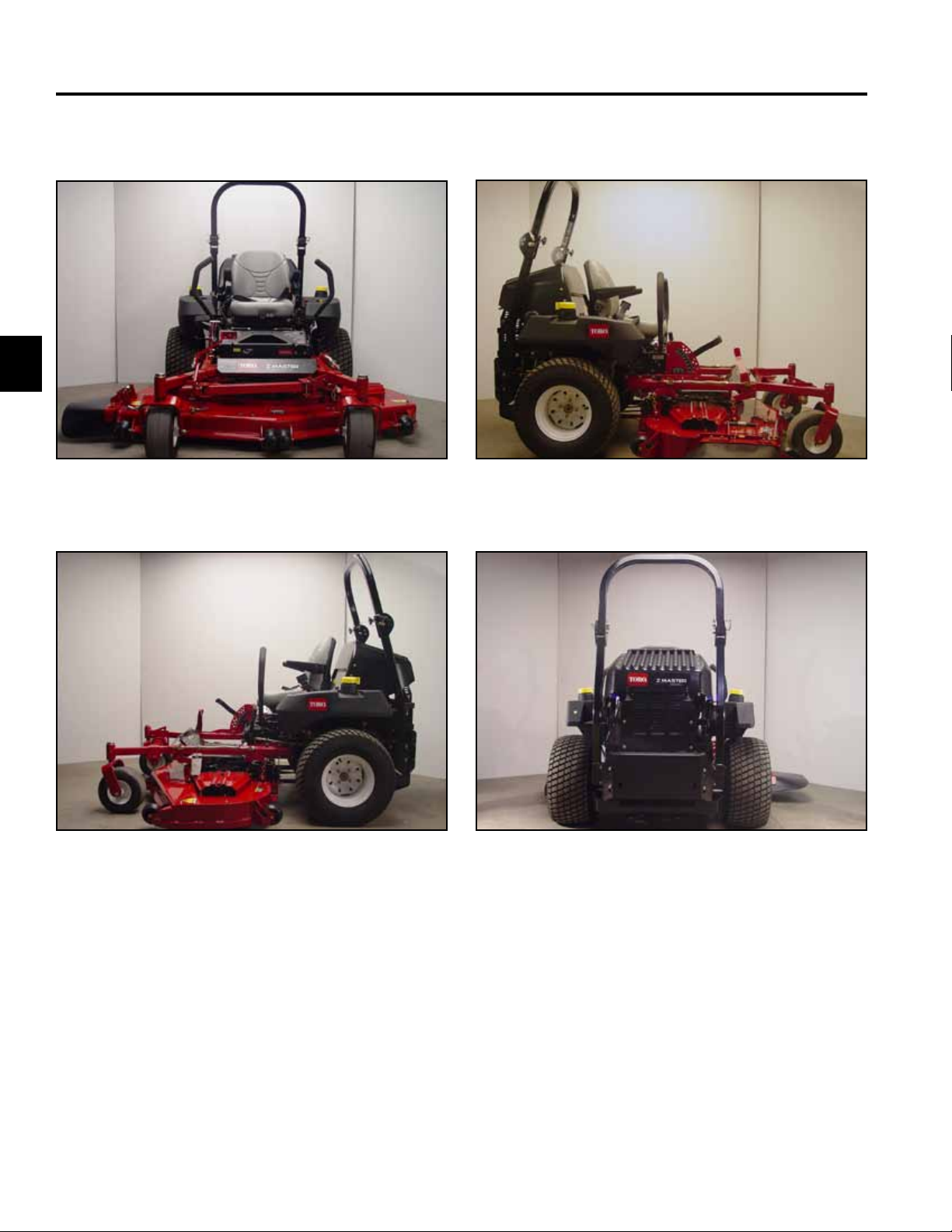
SPECIFICATIONS
MACHINE PROFILE PHOTOS
Fig 001 DSC-2789
Fig 002 DSC-2790 Fig 004 DSC-2794
Fig 003 DSC-2792
2-2 Z Master Z597 Diesel Service Manual
Page 12

SPECIFICATIONS
Item Specication
Engine Briggs & Stratton® Vanguard™ Daihatsu® 27 Horsepower Diesel Engine
RPM setting High RPM Setting (no load) 3850 + 50 (International: 3450 + 50)
Low RPM Setting 1750
Fuel Capacity 12 gallons (45.4 liters) Diesel Fuel
Length Z597 – 60” (152.4cm) TF Deck - 81.5” (207cm)
Z597 – 72” (182.9cm) TF Deck - 84.5” (214.6cm)
Width Z597 – 60” (152.4cm) TF Deck - 61.7” (156.7cm) - Deector 76” (193cm)
Z597 – 72” (182.9cm) TF Deck - 73.6” (186.9cm) - Deector 88” (223.5cm)
Height 74” (188cm) ROPS Height Upright
55” (140cm) ROPS Folded
Weight Z597 – 60” (152.4cm) TF Deck - 1630 lbs. (739.36kg)
Z597 – 72” (182.9cm) TF Deck - 1695 lbs. (768.84kg)
Traction System (2) Hydro-Gear BDP-21A, 21cc/rev with system check relief (Pump)
(2) Parker/Ross MB18, 17.1 cir 1 ¼“ Tapered Shaft (Wheel Motor)
Ground Speed Forward: Innite 0 – 12 mph
Reverse: Innite 0 – 8 mph
Tires Rear: 26” x 12” – 12
Front: 13” x 6.5” – 6
Tire Pressure Rear: 13 psi (90kPa)
Front: 13 psi (90kPa)
Attachment Drive 200 ft-lb. electromagnetic clutch (271.16 Nm)
2
Battery BCI Group Size: 26
540 cold cranking amps.
2-3Z Master Z597 Diesel Service Manual
Page 13

2
SPECIFICATIONS
Item Specication
Mower Deck TURBO FORCE
Deck Construction Fabricated, High Strength 7-gauge Steel/with Bull-nose Bumper
Deck Depth 5 ½” (13.97cm)
Mower Bafes Adjustable Discharge Bafe
Spindle Housing 9 3/8” (23.8cm) Diameter Cast Iron
Spindle Shaft/Bearings 1” (2.54cm) Shaft / Tapered Roller
Blade Tip Speed 18,500+ ft/min (5,638+ m/min)
Blades ¼” (.635cm) Heat Treated Steel
Discharge Chute 5/16” (.79cm) Rubber
Cutting Height 1-1/2” – 5” (3.81 - 12.7cm)
Carrier Frame Construction 2” x 2” x 3/16” (5.08 x 5.08 x .476cm) Steel
Anti-scalp Rollers 6
Certication ANSI, CARB, EPA, OSHA
2-4 Z Master Z597 Diesel Service Manual
Page 14
SPECIFICATIONS
General Specications
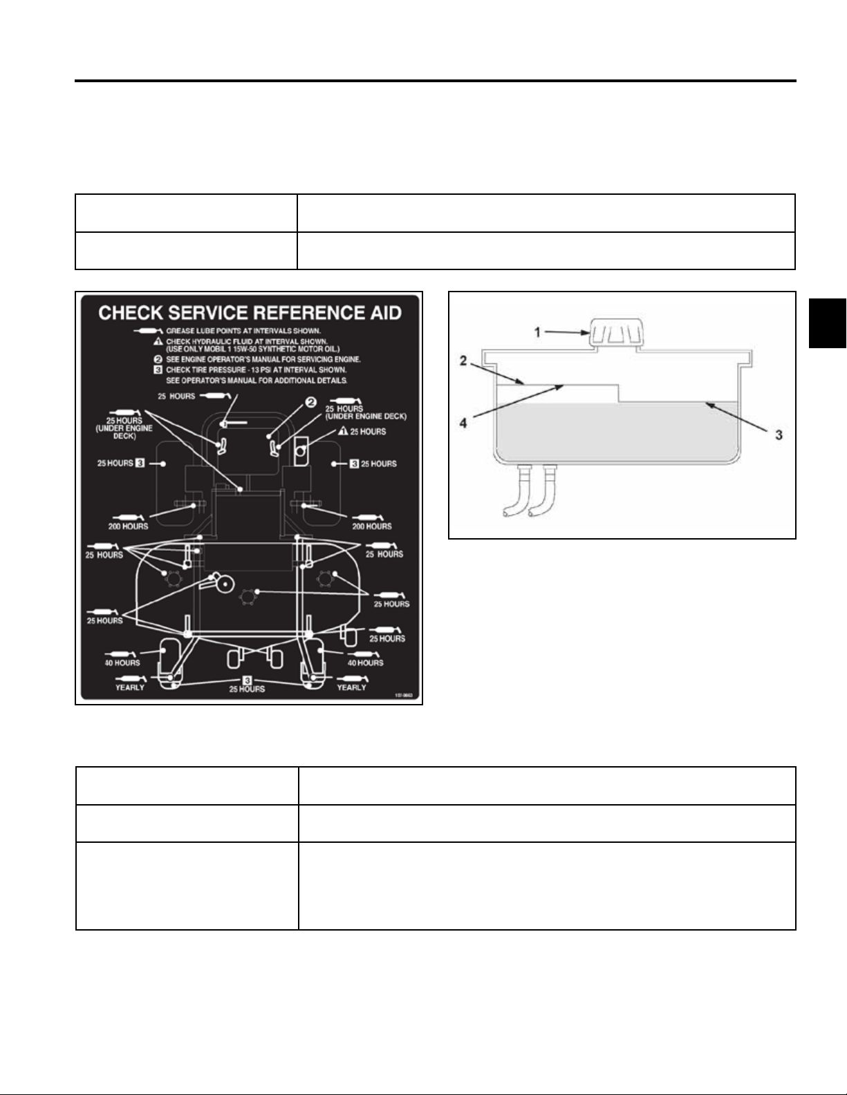
Greasing and Lubrication:
Grease: No. 2 general purpose lithium base or molybdenum grease.
Where to Add Grease: See Check Service Reference Aid decal below.
2
Fig 006 g. 55 m-5615
1. Cap 3. Cold uid level - full
2. Bafe 4. Hot uid level - full
Fig 005 g. 50 decal
Hydraulic System Oil Capacity: 4 quarts (3.8 l)
Fluid Type: Mobil 1 15W – 50 synthetic motor oil or equivalent synthetic oil
Fluid Level: Check the uid level while the uid is warm. The uid should be between cold
and hot.
Note: The uid level should be to the top of the hot level of the bafe,
when the uid is hot (Fig. 006 above).
2-5Z Master Z597 Diesel Service Manual
Page 15
SPECIFICATIONS
2
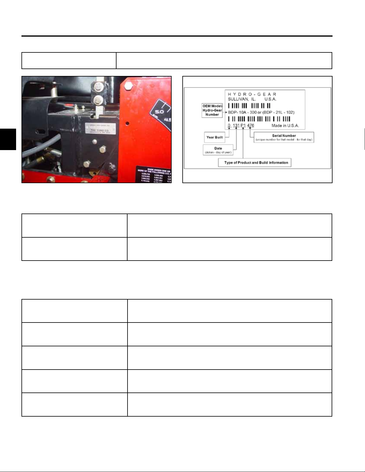
Model and Serial Number
Location
The unit model and serial number plate is located on the right hand side of the
unit, below the right side motion control lever (Fig. 007).
Fig 007 DSC-2351
Engine Model and Serial Number
Identication:
Consult the appropriate engine manufacture’s service literature for the
location and translation of the engine model and serial number information.
Fig 008 conguration
Hydrostatic Pumps Model and Serial
Number:
The label above (Fig. 008), can be located on the pump housing. It
identies the model and conguration of the BDP pump.
Available Service Manuals / Service Aids
Hydrostatic Pumps: Hydro-Gear BDP-10A/16A/21L – Service and Repair Manual
Form # 492-4789
Wheel Motors: Parker/Ross Wheel Motor Service Manual
Form # 492-4753
Diesel Engine: Briggs & Stratton Daihatsu 3 Cylinder Liquid-Cooled Engine Repair Manual
Form # 492-0670
Hydraulic Troubleshooting: Interactive hydraulic troubleshooting and failure analysis on compact disk
Form #492-4777
Electrical Troubleshooting: Interactive electrical troubleshooting and wiring diagrams on compact disk
Form #492-9143
2-6 Z Master Z597 Diesel Service Manual
Page 16
SPECIFICATIONS
Torque Specifications
Recommended fastener torque values are listed in the
following tables. For critical applications, as
determined by Toro, either the recommended torque or
a torque that is unique to the application is clearly
identified and specified in the service manual.
These torque specifications for the installation and
tightening of fasteners shall apply to all fasteners which
do not have a specific requirement identified in the
service manual. The following factors shall be
considered when applying torque: cleanliness of the
fastener, use of a thread sealant (Loctite), degree of
lubrication on the fastener, presence of a prevailing
torque feature, hardness of the surface underneath of
the fastener’s head, or similar condition which affects
the installation.
As noted in the following tables, torque values should
be reduced by 25% for lubricated fasteners to
achieve the similar stress as a dry fastener. Torque
values may also have to be reduced when the fastener
is threaded into aluminum or brass. The specific
torque value should be determined based on the
aluminum or brass material strength, fastener size,
length of thread engagement, etc.
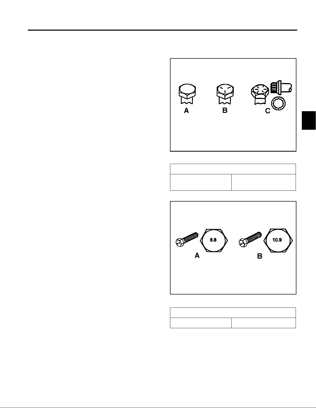
Fastener Identification
Inch Series Bolts and Screws
(A) Grade 1
(B) Grade 5
2
Figure A
(C) Grade 8
The standard method of verifying torque shall be
performed by marking a line on the fastener (head or
nut) and mating part, then back off fastener 1/4 of a
turn. Measure the torque required to tighten the
fastener until the lines match up.
Figure B
Metric Bolts and Screws
(A) Class 8.8 (B) Class 10.9
2-7Z Master Z597 Diesel Service Manual
Page 17

SPECIFICATIONS
SAE Grade 8 Bolts, Screws,
Studs, & Sems with Regular
2
Standard Torque for Dry, Zinc Plated, and Steel Fasteners (Inch Series)
2
Grade 1, 5, &
Thread Size
# 6 - 32 UNC
# 6 - 40 UNF 17 ± 2 190 ± 20 25 ± 2 280 ± 20
# 8 - 32 UNC
# 8 - 36 UNF 31 ± 3 350 ± 30 43 ± 4 31 ± 3
# 10 - 24 UNC
#10 - 32 UNF 48 ± 4 540 ± 45 68 ± 6 765 ± 70
1/4 - 20 UNC 48 ± 7 53 ± 7 599 ± 79 100 ± 10 1125 ± 100 140 ± 15 1580 ± 170
1/4 - 28 UNF 53 ± 7 65 ± 10 734 ± 113 115 ± 10 1300 ± 100 160 ± 15 1800 ± 170
5/16 - 18 UNC 115 ± 15 105 ± 17 1186 ± 169 200 ± 25 2250 ± 280 300 ± 30 3390 ± 340
5/16 - 24 UNF 138 ± 17 128 ± 17 1446 ± 192 225 ± 25 2540 ± 280 325 ± 30 3670 ± 340
3/8 - 16 UNC 16 ± 2 16 ± 2 22 ± 3 30 ± 3 41 ± 4 43 ± 4 58 ± 5
3/8 - 24 UNF 17 ± 2 18 ± 2 24 ± 3 35 ± 3 47 ± 4 50 ± 4 68 ± 5
7/16 - 14 UNC 27 ± 3 27 ± 3 37 ± 4 50 ± 5 68 ± 7 70 ± 7 68 ± 9
7/16 - 20 UNF 29 ± 3 29 ± 3 39 ± 4 55 ± 5 75 ± 7 77 ± 7 104 ± 9
1/2 - 13 UNC 30 ± 3 48 ± 7 65 ± 9 75 ± 8 102 ± 11 105 ± 10 142 ± 14
1/2 - 20 UNF 32 ± 3 53 ± 7 72 ± 9 85 ± 8 115 ± 11 120 ± 10 163 ± 14
5/8 - 11 UNC 65 ± 10 88 ± 12 119 ± 16 150 ± 15 203 ± 20 210 ± 20 285 ± 27
5/8 - 18 UNF 75 ± 10 95 ± 15 129 ± 20 170 ± 15 230 ± 20 240 ± 20 325 ± 27
3/4 - 10 UNC 93 ± 12 140 ± 20 190 ± 27 265 ± 25 359 ± 34 374 ± 35 508 ± 47
3/4 - 16 UNF 115 ± 15 165 ± 25 224 ± 34 300 ± 25 407 ± 34 420 ± 35 569 ± 47
7/8 - 9 UNC 140 ± 20 225 ± 25 305 ± 34 430 ± 45 583 ± 61 600 ± 60 813 ± 81
7/8 - 14 UNF 155 ± 25 260 ± 30 353 ± 41 475 ± 45 644 ± 61 660 ± 60 895 ± 81
8 with Thin
Height Nuts
In-lb In-lb N-cm In-lb N-cm In-lb N-cm
10 ± 2 13 ± 2 147 ± 23
13 ± 2 25 ± 5 282 ± 30
18 ± 2 30 ± 5 339 ± 56
ft-lb ft-lb N-m ft-lb N-m ft-lb N-m
SAE Grade 1 Bolts, Screws,
Studs, & Sems with Regular
Height Nuts (SAE J995
Grade 2 or Stronger Nuts)
SAE Grade 5 Bolts, Screws,
Studs, & Sems with Regular
Height Nuts (SAE J995
Grade 2 or Stronger Nuts)
15 ± 2 170 ± 20 23 ± 2 260 ± 20
29 ± 3 330 ± 30 41 ± 4 460 ± 45
42 ± 4 475 ± 45 60 ± 6 674 ± 70
Height Nuts (SAE J995
Grade 2 or Stronger Nuts)
Note: Reduce torque values listed in the table above
by 25% for lubricated fasteners. Lubricated fasteners
are defined as threads coated with a lubricant such as
oil, graphite, or thread sealant such as Loctite.
Note: The nominal torque values listed above for
Grade 5 and 8 fasteners are based on 75% of the
minimum proof load specified in SAE J429. The
tolerance is approximately
value. Thin height nuts include jam nuts.
± 10% of the nominal torque
Note: Torque values may have to be reduced when
installing fasteners into threaded aluminum or brass.
The specific torque value should be determined based
on the fastener size, the aluminum or base material
strength, length of thread engagement, etc.
2-8 Z Master Z597 Diesel Service Manual
Page 18

SPECIFICATIONS
Standard Torque for Dry, Zinc, and Steel Fasteners (Metric Fasteners)
Class 8.8 Bolts, Screws, and Studs with
Thread Size
M5 X 0.8 57 ± 5 in-lb 640 ± 60 N-cm 78 ± 7 in-lb 885 ± 80 N-cm
M6 X 1.0 96 ± 9 in-lb 1018 ± 100 N-cm 133 ± 13 in-lb 1500 ± 150 N-cm
M8 X 1.25 19 ± 2 ft-lb 26 ± 3 N-m 27 ± 2 ft-lb 36 ± 3 N-m
M10 X 1.5 38 ± 4 ft-lb 52 ± 5 N-m 53 ± 5 ft-lb 72 ± 7 N-m
M12 X 1.75 66 ± 7 ft-lb 90 ± 10 N-m 92 ± 9 ft-lb 125 ± 12 N-m
M16 X 2.0 166 ± 15 ft-lb 225 ± 20 N-m 229 ± 22 ft-lb 310 ± 30 N-m
M20 X 2.5 325 ± 33 ft-lb 440 ± 45 N-m 450 ± 37 ft-lb 610 ± 50 N-m
Note: Reduce torque values listed in the table above
by 25% for lubricated fasteners. Lubricated fasteners
are defined as threads coated with a lubricant such as
oil, graphite, or thread sealant such as Loctite.
Note: Torque values may have to be reduced when
installing fasteners into threaded aluminum or brass.
The specific torque value should be determined based
on the fastener size, the aluminum or base material
strength, length of thread engagement, etc.
Regular Height Nuts
(Class 8 or Strong Nuts)
Note: The nominal torque values listed above are
based on 75% of the minimum proof load specified in
SAE J1199. The tolerance is approximately
the nominal torque value. Thin height nuts include jam nuts.
Class 10.9 Bolts, Screws, and Studs with
Regular Height Nuts (
Class 10 or Strong Nuts)
2
± 10% of
2-9Z Master Z597 Diesel Service Manual
Page 19

SPECIFICATIONS
Other Torque Specifications
2
SAE Grade 8 Steel Set Screws
Recommended Torque
Thread Size
Square Head Hex Socket
1/4 - 20 UNC 140 ± 20 in-lb 73 ± 12 in-lb
5/16 - 18 UNC 215 ± 35 in-lb 145 ± 20 in-lb
3/8 - 16 UNC 35 ± 10 ft-lb 18 ± 3 ft-lb
1/2 - 13 UNC 75 ± 15 ft-lb 50 ± 10 ft-lb
Thread Cutting Screws
(Zinc Plated Steel)
Type 1, Type 23, or Type F
Thread Size Baseline Torque*
No. 6 - 32 UNC 20 ± 5 in-lb
Wheel Bolts and Lug Nuts
Thread Size Recommended Torque**
7/16 - 20 UNF
Grade 5
1/2 - 20 UNF
Grade 5
M12 X 1.25
Class 8.8
M12 X 1.5
Class 8.8
** For steel wheels and non-lubricated fasteners.
Thread Cutting Screws
Thread
Size
No. 6 18 20 20 ± 5 in-lb
Threads per Inch
Type A Type B
65 ± 10 ft-lb 88 ± 14 N-m
80 ± 10 ft-lb 108 ± 14 N-m
80 ± 10 ft-lb 108 ± 14 N-m
80 ± 10 ft-lb 108 ± 14 N-m
(Zinc Plated Steel)
Baseline Torque*
No. 8 - 32 UNC 30 ± 5 in-lb
No.10 - 24 UNC 38 ± 7 in-lb
1/4 - 20 UNC 85 ± 15 in-lb
5/16 - 18 UNC 110 ± 20 in-lb
3/8 - 16 UNC 200 ± 100 in-lb
Conversion Factors
in-lb X 11.2985 - N-cm
ft-lb X 1.3558 = N-m
No. 8 15 18 30 ± 5 in-lb
No. 10 12 16 38 ± 7 in-lb
No. 12 11 14 85 ± 15 in-lb
* Hole size, material strength, material thickness and
finish must be considered when determining specific
torque values. All torque values are based on nonlubricated fasteners.
N-cm X - 0.08851 = in-lb
N-cm X 0.73776 - ft-lb
2-10 Z Master Z597 Diesel Service Manual
Page 20

SPECIFICATIONS
Equivalents and Conversions
Decimal and Millimeter Equivalents
Fractions Decimals mm Fractions Decimals mm
1/64 0.015625 0.397 33/64 0.515625 13.097
1/32 0.03125 0.794 16/32 0.53125 13.484
3/64 0.046875 1.191 35/64 0.546875 13.891
1/16 0.0625 1.588 9/16 0.5625 14.288
5/64 0.078125 1.984 37/64 0.578125 14.684
3/32 0.9375 2.381 19/32 0.59375 15.081
1/8 0.1250 3.175 5/8 0.6250 15.875
9/64 0.140625 3.572 41/64 0.640625 16.272
5/32 0.15625 3.969 21/32 0.65625 16.669
11/64 0.171875 4.366 43/64 0.671875 17.066
3/16 0.1875 4.762 11/16 0.6875 17.462
13/64 0.203125 5.159 45/64 0.703125 17.859
7/32 0.21875 5.556 23/32 0.71875 18.256
15/64 0.234375 5.953 47/64 0.734375 18.653
1/4 0.2500 6.350 3/4 0.7500 19.050
17/64 0.265625 6.747 49/64 0.765625 19.447
9/32 0.28125 7.144 25/32 0.78125 19.844
19/64 0.296875 7.541 51/64 0.796875 20.241
5/16 0.3125 7.541 13/16 0.8125 20.638
21/64 0.328125 8.334 53/64 0.828125 21.034
11/32 0.34375 8.731 27/32 0.84375 21.431
23/64 0.359375 9.128 55/64 0.859375 21.828
3/8 0.3750 9.525 7/8 0.8750 22.225
25/64 0.390625 9.922 57/64 0.890625 22.622
13/32 0.40625 10.319 29/32 0.90625 23.019
27/64 0.421875 10.716 59/64 0.921875 23.416
7/16 0.4375 11.112 15/16 0.9375 23.812
29/64 0.453125 11.509 61/64 0.953125 24.209
15/32 0.46875 11.906 31/32 0.96875 24.606
31/64 0.484375 12.303 63/64 0.984375 25.003
1/2 0.5000 12.700 1 1.000 25.400
1 mm = 0.03937 in. 0.001 in. = 0.0254 mm
2
2-11Z Master Z597 Diesel Service Manual
Page 21

2
SPECIFICATIONS
U.S. to Metric Conversions
To Convert Into Multiply By
Miles
Yards
Linear
Measurement
Area
Volume
Weight
Pressure
Work
Liquid Volume
Liquid Flows
Temperature
Feet
Feet
Inches
Inches
Inches
Square Miles
Square Feet
Square Inches
Acre
Cubic Yards
Cubic Feet
Cubic Inches
Tons (Short)
Pounds
Ounces
Pounds/Sq. In. Kilopascal
Foot-pounds
Foot-pounds
Inch-pounds
Quarts
Gallons
Gallons/Minute Liters/Minute
Fahrenheit Celsius
Kilometers
Meters
Meters
Centimeters
Meters
Centimeters
Millimeters
Square Kilometers
Square Meters
Square Centimeters
Hectare
Cubic Meters
Cubic Meters
Cubic Centimeters
Metric Tons
Kilograms
Grams
Newton-Meters
Kilogram-Meters
Kilogram-Centimeters
Liters
Liters
1.609
0.9144
0.3048
30.48
0.0254
2.54
25.4
2.59
0.0929
6.452
0.4047
0.7646
0.02832
16.39
0.9078
0.4536
28.3495
6.895
1.356
0.1383
1.152144
0.9463
3.785
3.785
1. Subtract 32°
2. Multiply by 5/9
2-12 Z Master Z597 Diesel Service Manual
Page 22

CHASSIS
Safety Information . . . . . . . . .
Specications . . . . . . . . . . .
Chassis . . . . . . . . . . . . . .
Hydraulic System . . . . . . . . .
Engine . . . . . . . . . . . . . . .
1
1
2
3
4
5
Electrical . . . . . . . . . . . . . .
Mower Decks . . . . . . . . . . .
3-1Z Master Z597 Diesel Service Manual
6
7
Page 23
CHASSIS
3
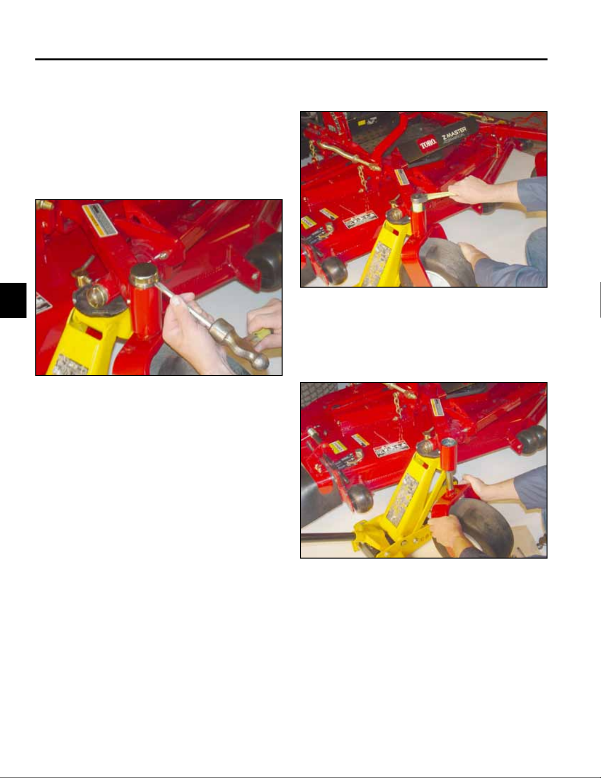
Caster Fork Assembly Removal
1. Raise the front of the unit off the ground, allowing
enough clearance to remove the castor fork from the
bottom of the hub.
2. With a hammer and chisel, remove the top grease
cap (Fig. 009).
3. Remove the locknut (Fig. 010).
Fig 010 DSC-1532
4. Remove the Belleville washers, caster fork and
wheel assembly (Fig. 011).
Fig 009 mvc-1531
Fig 011 DSC-1533
3-2 Z Master Z597 Diesel Service Manual
Page 24
CHASSIS
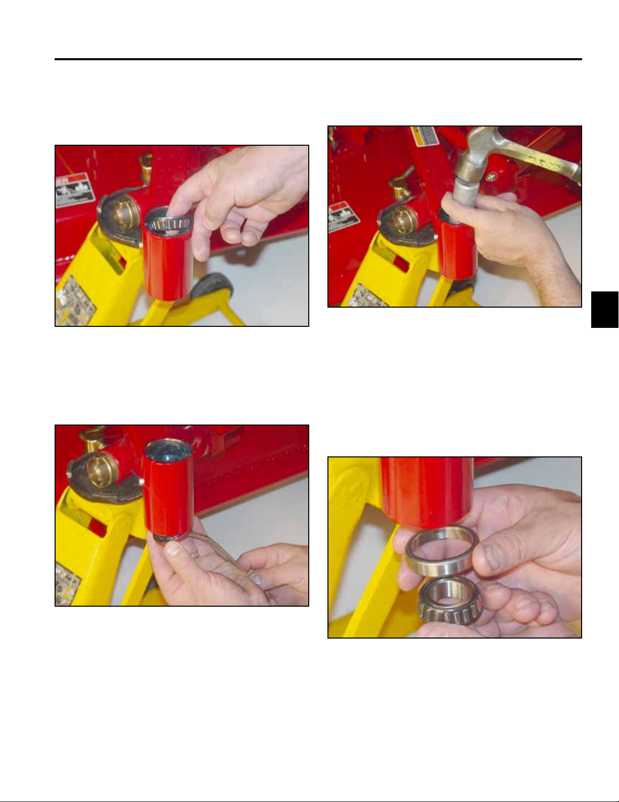
Replacing the Caster Bearings
1. Remove the top tapered roller bearing (Fig. 012).
Fig 012 DSC-1534
2. Remove bottom seal and tapered roller bearing (Fig.
013).
3. With a driver and hammer, remove both the bottom
and top tapered bearing cups (Fig. 014).
Fig 014 DSC-1536
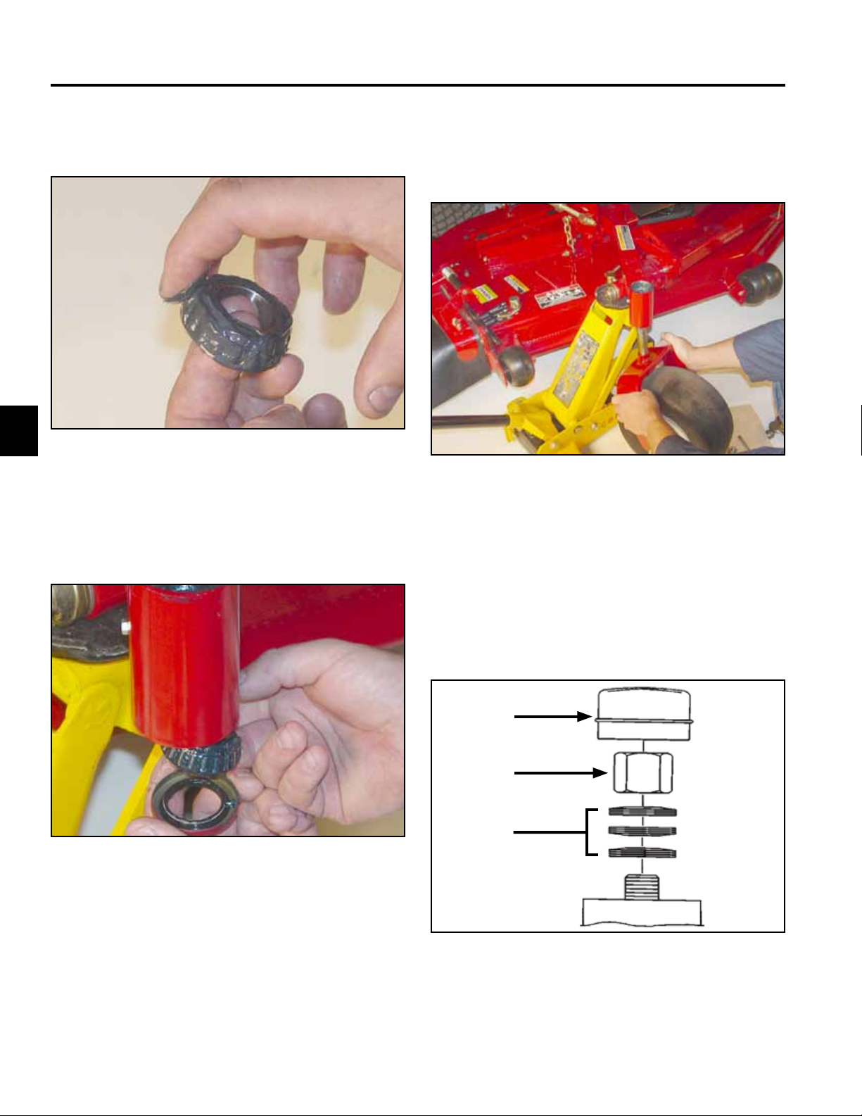
4. With a driver and hammer, install new bearing
cups. The bearing cups are tapered; make sure the
tapered/thicker end of the cup is installed inward for
the top and bottom end (Fig. 015). Tap the bearing
cups in until they seat against the step in the caster
hub.
3
Fig 013 DSC-1535
Fig 015 DSC-1537
3-3Z Master Z597 Diesel Service Manual
Page 25
CHASSIS
3
5. Pack the upper and lower tapered bearings prior to
installation (Fig. 016).
Fig 016 DSC-1539
6. Install the lower bearing and seal, with the open end
of the seal facing up (Fig. 017).
Castor Fork Assembly
1. Install the castor fork into the frame (Fig. 018).
Fig 018 DSC-1533
2. Install the upper bearing.
Fig 017 DSC-1538
3. Install the Belleville (spring) washers as shown in
(Fig. 019).
A. Dust Cap
B. Locknut
C. Spring Washers
A
B
C
Fig 019 washers line art
3-4 Z Master Z597 Diesel Service Manual
Page 26
CHASSIS
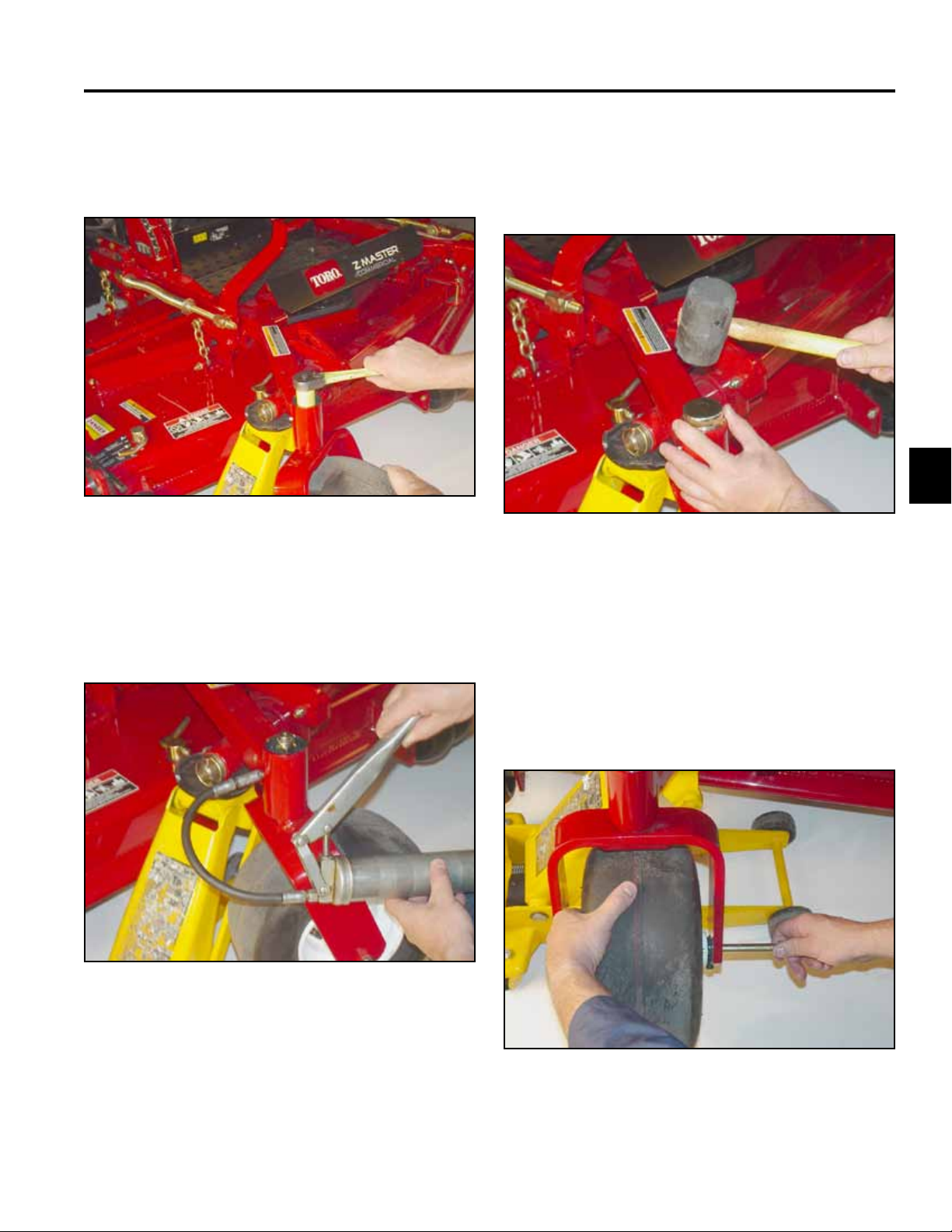
4. Install the locknut and tighten until the spring
washers are at, then back off 1/4 turn to properly
set the preload on the bearings (Fig. 020).
Fig 020 DSC-1532
6. Remove the grease tting and install the grease
plug.
7. Install the dust cap on the caster hub (Fig. 022).
3
Fig 022 DSC-1541
5. Remove the plug located on the side of the hub
on the frame for the castor fork. Install a grease
tting. Pump grease into the housing until grease is
passing through the upper bearing (Fig. 021).
Fig 021 DSC-1540
Front Wheel Removal and Bearing
Replacement
1. Raise the front of the unit off the ground.
2. Remove the wheel bolt from the fork (Fig. 023).
Fig 023 DSC-1543
3-5Z Master Z597 Diesel Service Manual
Page 27
CHASSIS
3
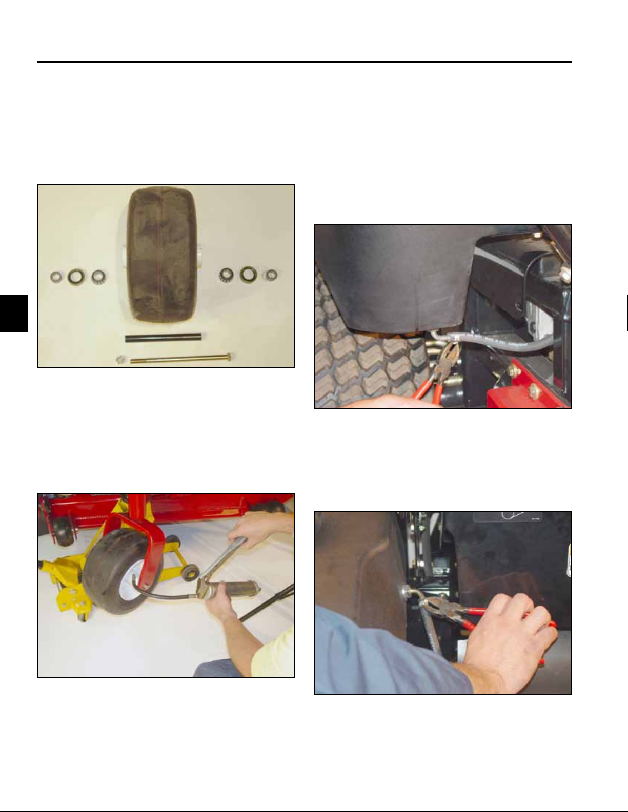
3. Remove bearing spacers and the front caster
spacer. Remove the seals located on each side of
the wheel and both the tapered bearings (Fig. 024).
A. Bearing Spacer D. Caster Spacer
B. Bearing Seal E. Retaining wheel nut
C. Taper Bearing F. Retaining wheel bolt
B
C
D
E
B
C
AA
F
Fig 024 DSC-1546
Fuel Tank Removal
Right Side Fuel Tank Removal
1. Disconnect the negative battery cable. Empty the
fuel tank.
2. Remove the fuel hose at the bottom of the fuel tank
(Fig. 026).
4. Pack both tapered wheel bearings. Reassemble
per Fig. 024. Pump grease into the wheel bearings
through the grease tting located on the rim (Fig.
025).
Fig 025 DSC-1547
Fig 026 DSC-1548
3. Remove the fuel return line located on the inside of
the fuel tank (Fig. 027).
Fig 027 DSC-1549
3-6 Z Master Z597 Diesel Service Manual
Page 28
CHASSIS
4. Remove the front bolt, spacer, washer, and nut that
secure the fuel tank bracket to the frame (Fig. 028).
Fig 028 DSC-1550
5. Remove the bolt, washer, and nut securing the left
rear of the fuel tank bracket to the frame (Fig. 029).
6. Remove bolt, washer, and nut securing the right rear
of the fuel tank bracket to the frame (Fig. 030).
3
Fig 030 DSC-1553
7. Remove the tank from the frame (Fig. 031).
Fig 029 DSC-1552
Fig 031 DSC-1555
3-7Z Master Z597 Diesel Service Manual
Page 29
CHASSIS
3
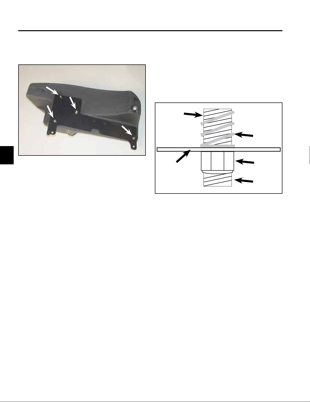
8. Remove the fuel tank bracket by removing 3
locknuts and springs and 1 bolt (Fig. 032).
Fig 032 DSC-1556
Right Side Fuel Tank Installation
Reverse the order of removal.
Note: When tightening the nuts and springs on the
fuel tank bracket, Do Not over-tighten the
nuts. Tighten the nuts until there are three
threads showing on the threaded stud (Fig.
033).
A
B
C
D
E
Fig 033 3 thread above nut
A. Tank Stud D. Nut
B. Compression Spring E. 3 Threads
C. Tank mounting Plate
Left Side Fuel Tank Removal
1. Disconnect the negative battery cable. Empty the
fuel tank.
3-8 Z Master Z597 Diesel Service Manual
Page 30
CHASSIS
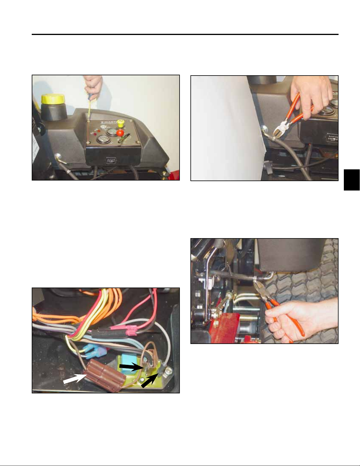
2. Remove the 4 screws retaining the control panel and
control panel shield to the tank (Fig. 034).
Fig 034 DSC-1563
3. Carefully remove the control panel and control panel
shield by lifting the panel and sliding it to the middle
of the unit.
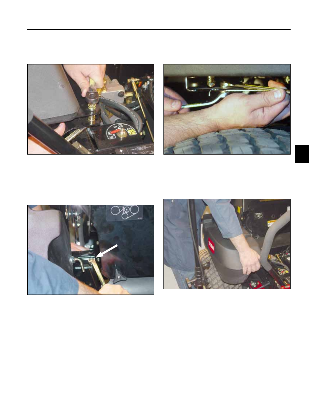
5. Remove the return fuel line, located on the inside of
the fuel tank (Fig. 036).
3
Fig 036 DSC-1565
6. Remove the fuel line, located under the front of the
fuel tank (Fig. 037).
NOTE: It is not necessary to disconnect any cables
or wiring.
4. Unplug the 3 connectors that plug into the delay
module (Fig. 035).
Fig 035 DSC-1578
Fig 037 DSC-1566
3-9Z Master Z597 Diesel Service Manual
Page 31

CHASSIS
3
7. Remove the front bolt, spacer, washer, and nut that
secure the fuel tank bracket to the frame (Fig. 038).
Fig 038 DSC-1568
8. Remove the bolt, washer, and nut that retain the fuel
tank bracket to the frame. They are located under
the right rear of the fuel tank (Fig. 039).
9. Remove the bolt, washer, and nut that retain the fuel
tank bracket to the frame. They are located under
the left rear of the fuel tank (Fig. 040).
Fig 040 DSC-1573
10. Remove the fuel tank from the frame (Fig. 041).
Fig 041 DSC-1575
Fig 039 DSC-1571
3-10 Z Master Z597 Diesel Service Manual
Page 32

CHASSIS
11. Remove the fuel tank bracket by removing 3
locknuts, springs, and 1 bolt (Fig. 042).
Fig 042 DSC-1576
Left Side Fuel Tank Installation
Hood Assembly Removal
1. Unhook the two rubber latches located on the rear of
the hood.
2. Remove the two hairpins, clevis pins, and washers
located in the front left and right side of the hood
(Fig. 044).
3
Reverse the order of removal.
Note: When tightening the nuts and bolts, Do Not
over-tighten the nuts. Tighten until there
are 3 threads showing on the threaded stud
(Fig. 043).
A
B
C
D
E
Fig 043 3 thread above nut
A. Tank Stud D. Nut
B. Compression Spring E. 3 Threads
C. Tank mounting Plate
Fig 044 DSC-1579
3. Lift the hood and remove the stop lanyards located
on each side of the hood. Remove the hood from the
frame of the unit (Fig. 045).
Fig 045 DSC-1581
3-11Z Master Z597 Diesel Service Manual
Page 33

CHASSIS
3
Hood Assembly Installation
Reverse the order of removal.
Throttle Control Replacement
1. Disconnect the negative battery cable.
2. Remove the 4 screws retaining the control panel to
the fuel tank (Fig. 046).
4. Remove the two locknuts and carriage bolts
retaining the throttle cable assembly (Fig. 048).
Fig 048 DSC-1591
5. Disconnect the end of throttle cable at the swivel
clamp, located on the throttle linkage at the injector
pump (Fig. 049).
Fig 046 DSC-1584
3. Remove the ball knob located on the throttle control
by applying upward pressure under the knob (Fig.
047).
Fig 049 DSC-1592
Fig 047 DSC-1586
3-12 Z Master Z597 Diesel Service Manual
Page 34

CHASSIS
6. Loosen the screw on the throttle casing clamp and
remove the throttle cable (Fig. 050).
Fig 050 DSC-1593
7. Keeping the tie straps in place, slide the throttle
cable through the two tie straps to remove it from the
machine. One tie strap is located at the radiator fan
motor mount, Ref. A, and the other is at the engine
removal bracket, Ref. B (Fig. 051).
NOTE: DO NOT cut or remove the tie straps.
Installation
1. Install the throttle control in the control plate. Install
the two carriage bolts and nuts and tighten (Fig.
052).
3
Fig 052 DSC-1596
2. Feed the throttle cable through the tie strap on the
radiator fan motor mount (Fig. 053).
A
B
Fig 051 DSC-1594
Fig 053 DSC-1597
3-13Z Master Z597 Diesel Service Manual
Page 35

CHASSIS
3
3. Route the throttle cable through the tie strap located
on the engine lifting bracket (Fig. 054).
Fig 054 DSC-1599
4. The throttle cable is then routed around the fuel
pump injector lines and through the swivel clamp.
5. Install the throttle cable on the inside of the casing
clamp, DO NOT tighten (Fig. 056).
Fig 056 DSC-1605
6. Install control panel to the fuel tank mount location
(Fig. 057).
Note: The cable wire should be routed through the
swivel clamp, with the swivel clamp washer
located under the cable wire (Fig. 055).
A
B
Fig 055 DSC-1600
A. Cable wire B. Washer
Fig 057 DSC-1606
3-14 Z Master Z597 Diesel Service Manual
Page 36

CHASSIS
7. Install throttle control knob and position throttle
control lever to the idle position (Fig. 058).
Fig 058 DSC-1608
8. Position the throttle cable swivel clamp until 1/4”
(6.35mm) of the throttle cable wire protrudes through
the opposite end of the clamp. Carefully tighten the
swivel clamp screw (Fig. 059).
9. Tighten the cable housing clamp (Fig. 060).
Fig 060 DSC-1616
10. Move the throttle control lever to the Full speed
position. Verify injector pump arm contacts the high
speed stop screw (Fig. 061).
3
Fig 059 DSC-1614
Fig 061 DSC-1617
3-15Z Master Z597 Diesel Service Manual
Page 37

CHASSIS
3
Brake Lever Removal
1. Release the parking brake (forward position).
2. Remove the cotter pin and clevis pin from the brake
rod yoke (Fig. 062).
Fig 062 DSC-1618
4. Remove the brake shaft cotter pin (Fig. 064).
Fig 064 DSC-1620
5. Slide the brake shaft out of the frame pivot bushings
(Fig 065).
3. Lift the oor pan assembly to access the brake lever
shaft and cotter pin (Fig. 063).
Fig 063 DSC-1619
Fig 065 DSC-1621
3-16 Z Master Z597 Diesel Service Manual
Page 38

CHASSIS
6. Using a hammer and punch, drive both brake lever
control bearings from the brake pivot (Fig. 066).
Fig 066 DSC-1622
7. Inspect the brake shaft and bushings for excessive
wear. Replace any worn or broken components
(Fig. 067).
Brake Lever Installation
Reverse the order of removal
Brake Band Removal
1. Raise the left rear tire off the ground (Fig. 068).
3
A
B
Fig 067 DSC-1623
A. Brake Lever C. Cotter Pin
B. Bushings
C
Fig 068 DSC-1624
2. Remove the four wheel lug bolts.
3-17Z Master Z597 Diesel Service Manual
Page 39

CHASSIS
3
3. Remove bolts, brake band retainer, spacers, and
brake band (Fig. 069).
A. 3 Bolts
B. Brake Band Retainer
C. 3 Spacers
D. Brake Band
A
B
C
D
Fig 069 DSC-1626
2. Install the 3 bolts, brake band retainer, brake band,
and spacers and tighten (Fig. 071).
Fig 071 DSC-1631
3. Install tire assembly and the 4 wheel bolts.
Brake Band Installation
1. Install the brake band around the wheel hub (Fig.
070).
Fig 070 DSC-1629
Brake Cross Shaft Removal
1. Raise the rear end of the unit and remove the right
and left rear tires.
Note: To prevent the unit from rolling, block the two
front tires.
3-18 Z Master Z597 Diesel Service Manual
Page 40

CHASSIS
2. Remove the clevis spring pin from the brake rod and
remove the rod (Fig. 072).
Fig 072 DSC-1632
3. Remove the cotter pin and clevis pin from the left
side lower brake linkage assembly (Fig. 073).
4. On the right side, remove the cotter pin and clevis
pin from the lower brake linkage assembly (Fig. 074).
3
Fig 074 DSC-1634
5. On the right side, remove the two bolts and nuts
holding the ange bearing (Fig. 075).
Fig 073 DSC-1633
Fig 075 DSC-1635
3-19Z Master Z597 Diesel Service Manual
Page 41

CHASSIS
3
6. On the left side, remove the two bolts, spacers, and
nuts holding the ange bearing (Fig. 076).
Fig 076 DSC-1636
7. Remove the brake shaft from the frame (Fig. 077).
8. Inspect brake shaft and ange bushings for
excessive wear (Fig. 078).
A
C
B
D
D
E
Fig 078 DSC-1638
A. RH Mounting Bolts D. Flange Bearing
B. Brake Shaft E. Spacers
C. LH Mounting Bolts
Fig 077 DSC-1637
Brake Shaft Installation
1. Install the ange bearing on the right side of the
shaft. From the outside of the frame, align the ange
bearing holes with the frame mounting holes. Install
mounting hardware and tighten (Fig. 079).
Fig 079 DSC-1640
3-20 Z Master Z597 Diesel Service Manual
Page 42

CHASSIS
2. Install the ange bearing over the left side of the
brake shaft, ange facing outward. Install mounting
bolts from the outside of the ange, through brake
retainer spacers, and through the frame.
Note: Before tightening the mounting hardware,
be sure that the brake lever arm is pointing
upward between the mounting hardware (Fig.
080).
A
B
C
Fig 080 DSC-1641
A. Brake Lever Arm C. Bolt
B. Spacer
3. Install clevis pin connecting the lower brake
assembly to brake shaft. Install cotter pin into clevis
pin (Fig. 081). Repeat procedure for right side.
3
Fig 081 DSC-1643
4. Install clevis spring pin connecting brake rod to
brake shaft. Rotate clevis spring pin until it clips onto
brake rod clevis (Fig. 082).
Fig 082 DSC-1644
5. Install left and right rear tires. Torque wheel
mounting bolts to 95 ft-lbs (128.8 Nm).
3-21Z Master Z597 Diesel Service Manual
Page 43

CHASSIS
3
Adjusting the Parking Brake
Check the parking brake for proper adjustment.
1. Disengage the brake lever (lever down).
2. Measure the length of the spring. The measurement
should be 2-3/4” (70mm) between the washers (Fig.
083).
11 11
10
Fig 083 m-7417
1. Brake lever - engaged 7. 1/4 - 5/16” (5 - 8mm)
2. Brake lever - disengaged 8. Spring bracket
3. Spring, 2-3/4” (70mm) 9. Lock nut below trunion
4. Jam nut above trunion roller roller
5. Nut below spring bracket 10. Brake rod
6. Trunion roller 11. Yoke
3. If an adjustment is necessary, loosen the jam nut
below the spring and tighten the nut directly below
the yoke (Fig. 083). Turn the nut until the correct
measurement is obtained. Tighten the two nuts
together and repeat on the opposite side of the unit.
4. Turn the nuts clockwise to shorten the spring length
and counterclockwise to lengthen the spring.
5. Engage the parking brake (lever up).
6. Measure the distance between the spring bracket
and the adjusting nut under spring bracket. The
measurement should be 1/4 - 5/16” (5 - 8mm) (Fig.
083).
7. If adjustment is necessary, loosen the jam nut
directly above the trunion roller. Turn the lock
nut below the trunion roller until the correct
measurement is obtained (Fig. 083).
8. Tighten the jam nut directly above the trunion roller
(Fig. 083).
Note: If the 1/4 - 5/16” (5 - 8mm) can not be
achieved, remove a pin from either yoke at the
ends of the brake rod. Adjust the length of the
rod so 1/4 - 5/16” (5 - 8mm) can be achieved
and install the brake rod.
3-22 Z Master Z597 Diesel Service Manual
Page 44

CHASSIS
Deck Lift Lever Removal
1. Park the machine on a level surface, disengage the
blade control (PTO), and turn the ignition key to OFF
to stop the engine. Remove the ignition key.
2. Remove the lower stop bolt from the deck lift plate
(Fig. 084).
Fig 084 DSC-1647
4. Loosen jam nuts on LH and RH deck lift rods until
deck support springs are fully extended (Fig. 086).
3
Fig 086 DSC-1649
5. Remove hex nut from RH rear deck lift assembly.
Repeat procedure for LH rear deck lift assembly
(Fig. 087).
3. With the mower deck in the transport position, place
a 4”x 4” block under each corner of the deck. Lower
the mower deck onto the support blocks to remove
the weight from the support chains (Fig. 085).
Fig 085 DSC-1648
Fig 087 DSC-1650
3-23Z Master Z597 Diesel Service Manual
Page 45

CHASSIS
3
6. Lower lift lever to its lowest position. Rear deck
swivel mounts should clear deck lift rods on both
sides. The mower deck lift linkage should now be
fully unloaded (Fig. 088).
A
Fig 088 DSC-1651
A. Lift Lever at lowest position
8. Loosen the top hex head ange nut at the deck lift
plate mounting location. Pivot the INNER deck lift
plate up and back toward the RH motion control
lever (Fig. 090).
Fig 090 DSC-1653
7. Remove hex bolt, nut, and lift lever bushing from the
lower deck lift plate mounting location (Fig. 089).
Fig 089 DSC-1652
9. Lift the oor pan assembly to its fully opened
position (Fig. 091).
Fig 091 DSC-1654
3-24 Z Master Z597 Diesel Service Manual
Page 46

CHASSIS
10. Remove hex bolt, bushing, and nylock nut
connecting the deck lift arm plates to the mower
deck rear cross-shaft lift assembly (Fig. 092).
Fig 092 DSC-1655
11. Remove retainer clip from lift lever (Fig. 093).
12. When removing the lift lever you may experience
interference with the RH oor pan hinge or the front
edge of the RH motion control plate, or both (Fig.
094).
A
Fig 094 DSC-1657
A. RH Floor pan hinge B. RH Motion control plate
B
3
Fig 093 DSC-1656
13. If the lift lever contacts the RH oor pan hinge,
loosen the RH oor pan hinge mounting hardware.
Push the RH hinge upward. Re-tighten the RH oor
pan hinge mounting hardware (Fig. 095).
A
Fig 095 DSC-1661
A. RH Floor pan hinge
3-25Z Master Z597 Diesel Service Manual
Page 47

CHASSIS
3
14. If the lift lever contacts the RH motion control plate,
tilt and hold the oor pan assembly slightly forward.
Move the RH motion control lever out of the neutral
lock position and push it in the full forward position.
Using a tie strap or wire, tie the oor pan assembly
to the motion control arm to hold the oor pan
assembly in place (Fig. 096).
Fig 096 DSC-1665
Deck Lift Lever Installation
1. For ease of installation, make sure deck lift arm
plates, bushing, and hardware are installed on the
lift lever grip assembly prior to installation as shown
(Fig. 098).
A
B
C
D
A
Fig 098 DSC-1668
A. Plate C. Bushing
B. Nut D. Bolt
15. Carefully slide the lift lever assembly out of its
carrier frame pivot (Fig. 097).
Fig 097 DSC-1667
2. Install lift lever assembly into front frame pivot
location (Fig. 099).
Fig 099 DSC-1670
3-26 Z Master Z597 Diesel Service Manual
Page 48

CHASSIS
3. Install retainer clip to lift lever shaft (Fig. 100).
Fig 100 DSC-1672
4. Install bushing into rear lift arm cross shaft (Fig.
101).
5. Install hex bolt through deck lift plates and rear
lift arm cross shaft bushing. Install nylock nut and
tighten (Fig. 102).
A
A
B
3
Fig 102 DSC-1675
A. Rear Lift Arm Plates B. Hex Bolt
A
Fig 101 DSC-1674
A. Bushing
6. Rotate deck lift plate (inner) downward until lower
mounting holes line up with hole in carrier frame and
deck lift plate (outer). From the outside of the frame,
install hex bolt, spacer, and anged lock nut as
shown. Tighten bolt (Fig. 103).
A B C
Fig 103 DSC-1677
A. Hex Bolt C. Flanged Lock Nut
B. Spacer
3-27Z Master Z597 Diesel Service Manual
Page 49

CHASSIS
3
7. Align rear deck mount swivels with ends of deck lift
rod (Fig. 104).
Fig 104 DSC-1680
8. Raise lift lever until deck mount swivels rest against
deck rod jam nuts. Install HOC pin into deck lift plate
height of cut holes to hold lift lever in this position
(Fig. 105).
9. Install lower “stop” bolt through inner and outer deck
lift plates. Install nylock nut and tighten until hex nut
and bolt are seated rmly against the deck lift plates.
DO NOT over-tighten or deck lift plates will deform
inward causing height of cut hitch pin assembly to
bind (Fig. 106).
Fig 106 DSC-1682
10. Install hex nut on end of deck lift rod. Tighten against
deck mount swivel. Repeat procedure for opposite
side deck lift rod (Fig. 107).
A
Fig 105 DSC-1681
A. HOC Pin
Fig 107 DSC-1683
3-28 Z Master Z597 Diesel Service Manual
Page 50

CHASSIS
11. Raise mower deck to the transport position. Remove
support blocks. Check deck level adjustment (refer
to the Leveling the Mower procedure, pg 7-46).
Readjust compression spring length by turning front
nut. Spring should be compressed to a length of
11-1/2” (29.2cm) between washers. Lock the front
nut into position by tightening the spring jam nut
(Fig. 108).
Motion Control Assembly Removal
1. Remove both oor pan assembly hinge bolts (Fig.
109).
3
Fig 109 DSC-1686
Fig 108 DSC-1685
12. Untie the oor pan assembly and lower. Return
motion control lever to its neutral locked position.
2. Remove oor pan assembly (Fig. 110).
Fig 110 DSC-1689
3-29Z Master Z597 Diesel Service Manual
Page 51

CHASSIS
3
3. Remove (4) pocket mounting bolts (Fig. 111).
Fig 111 DSC-1690
4. Remove pocket (Fig. 112).
5. Remove the two bolts retaining the lever assembly
to the control arm shaft (Fig. 113).
Fig 113 DSC-2062
6. Disconnect motion control dampener from motion
control assembly (Fig. 114).
Fig 112 DSC-1691
Fig 114 DSC-1695
3-30 Z Master Z597 Diesel Service Manual
Page 52

CHASSIS
7. Disconnect neutral switch wire harness from neutral
switch (Fig. 115).
Fig 115 DSC-1693
8. Remove bolt, spacer, and nut that retains the ball
joint to the motion control (Fig. 116).
9. Remove the cotter pin and clevis pin through the
adjustable yoke for the neutral return bolt (Fig. 117).
Fig 117 DSC-2064
10. Remove the two bolts and nuts that retain the ange
bearing on the inside of the motion control (Fig. 118).
3
Fig 116 DSC-2063
Fig 118 DSC-2066
3-31Z Master Z597 Diesel Service Manual
Page 53

CHASSIS
3
11. Remove the two bolts and nuts that retain the ange
bearing on the outside of the motion control (Fig.
119).
Fig 119 DSC-2067
Motion Control Assembly Installation
Reverse the order of removal
12. Remove the motion control from the frame (Fig.
120).
Fig 120 DSC-2068
3-32 Z Master Z597 Diesel Service Manual
Page 54

HYDRAULIC SYSTEM
Safety Information . . . . . . . . .
Specications . . . . . . . . . . .
Chassis . . . . . . . . . . . . . .
Hydraulic System . . . . . . . . .
Engine . . . . . . . . . . . . . . .
1
1
2
3
4
5
Electrical . . . . . . . . . . . . . .
Mower Decks . . . . . . . . . . .
4-1Z Master Z597 Diesel Service Manual
6
7
Page 55

HYDRAULIC SYSTEM
Hydrostatic Pump Removal
Note: Cleanliness is a key factor in a successful
repair of any hydrostatic system. Thoroughly
clean all exposed surfaces prior to any type
of maintenance. Cleaning all parts by using
a solvent wash and air drying is usually
adequate. As with any precision equipment,
all parts must be kept free of foreign material
and chemicals. Protect all exposed sealing
areas and open cavities from damage and
foreign material.
Upon removal, all seals, O-rings, and gaskets
should be replaced. Lightly lubricate all
seals, O-Rings and gaskets with clean
petroleum jelly prior to installation.
This procedure is showing the LH Hydrostatic Pump
being removed. Use these same procedures to remove
the RH Hydrostatic Pump.
1. Disconnect the negative and positive battery cables.
Remove the battery from the unit.
4. Using a 3/8” drive ratchet, insert the drive end into
the square hole in the pump belt tensioner arm.
Relieve the tension on the hydrostatic pump v-belt
and remove the belt (Fig. 122).
Fig 122 DSC-2073
4
2. Using compressed air, clean the area around the
hydrostatic pump. Perform additional cleaning as
needed to make sure it is free from any dirt and
debris.
3. Remove the two knobs located on the engine access
panel assembly. Remove both engine belt shield
and the engine access panel (Fig. 121).
5 Remove the bolt and nut retaining the hydro pump
control linkage to the hydro control arm (Fig. 123).
Fig 123 DSC-2081
Fig 121 DSC-2071
4-2 Z Master Z597 Diesel Service Manual
Page 56

HYDRAULIC SYSTEM
6. Remove the case drain hydraulic hose, located on
the left hand side of the hydrostatic pump (Fig. 124).
Note: When removing hydraulic hoses from the
pump, cap the hose and the tting on the
hydrostatic pump. This is to make sure dirt
and debris does not enter these areas.
7. Remove the two hydraulic hoses on the bottom of
the hydrostatic pump that go to the hydraulic motor
(Fig. 125). Install caps on the hydraulic hoses and
ttings.
Fig 125 DSC-2087
Fig 124 DSC-2083
Note: Before removing the hydraulic lines from
the hydrostatic pump, mark or tag one of the
hoses to make sure they are reconnected
correctly.
8. Remove the hydraulic suction line from the top of the
4
hydrostatic pump (Fig. 126). Install caps on the
hydraulic line and on the ttting.
Fig 126 DSC-2088
4-3Z Master Z597 Diesel Service Manual
Page 57

HYDRAULIC SYSTEM
4
9. Using a 12-point 3/8” socket, loosen the two set
screws located on the hydro pump hub Slide the
hydrostatic pump hub and pulley off the hydrostatic
pump shaft. Remove the key on the hydrostatic
pump shaft (Fig. 127).
Fig 127 DSC-2089
11. Cut the two cable ties that hold the fuel line and the
wiring harness (Fig. 129).
Fig 129 DSC-2092
12. Remove the hydrostatic pump from the frame (Fig.
130).
10. Loosen and remove the two bolts and nuts retaining
the hydrostatic pump to the frame (Fig. 128).
Fig 128 DSC-2091
Fig 130 DSC-2094
13. For service work on the hydrostatic pump refer to the
Hydro-Gear Service Manual, Form 492-4789.
4-4 Z Master Z597 Diesel Service Manual
Page 58

HYDRAULIC SYSTEM
Hydrostatic Pump Installation
Note: Prior to connecting the hydraulic lines,
replace the O-Rings with new ones and lightly
lubricate with petroleum jelly.
1. Install the hydrostatic pump to the frame. Install and
tighten the two bolts and nuts (Fig. 131).
Note: Before installing the pulley, replace the set
screws. The end of the set screws have a
knurled cup point for retention and must not
be re-used.
3. Install pulley and hydro pump hub on the hydrostatic
pump shaft and key. Align the center of the
hydrostatic pump pulley with the center of the idler
pulley (Fig. 133).
A
B
Fig 131 DSC-2091
2. Install the key on the hydrostatic pump shaft; make
sure the key is facing up on the shaft (Fig. 132).
4
Fig 133 DSC-2097
A. Pump pulley B. Idler Pulley
4. Tighten the two sets screws on the pulley using a 12point 3/8” (9.5mm) socket (Fig. 134).
Fig 132 DSC-2095
Fig 134 DSC-2089
4-5Z Master Z597 Diesel Service Manual
Page 59

HYDRAULIC SYSTEM
4
5. Install the hydraulic suction line on the top of the
hydrostatic pump (Fig. 135).
Fig 135 DSC-2088
6. Install the two hydraulic hoses that run from
the hydraulic wheel motor to the bottom of the
hydrostatic pump (Fig. 136).
7. Install the case drain hydraulic line, located on the
left hand side of the pump (Fig. 137).
Fig 137 DSC-2099
8. Install and tighten the bolt and nut retaining the
hydro pump control linkage to the hydro control arm
(Fig. 138).
Fig 136 DSC-2098
Remember to install the hydraulic hoses to the
correct port on the hydrostatic pump. If the lines are
reversed, the hydrostatic wheel motor will turn in the
direction opposite of motion control position.
Note: It may be easier to remove the rear tire
assembly for installation of the bottom and
side hydraulic hoses.
4-6 Z Master Z597 Diesel Service Manual
Fig 138 DSC-2081
Page 60

HYDRAULIC SYSTEM
9. Using a 3/8” drive ratchet, insert the wrench into
the square hole in the pump belt tensioner arm and
relieve the tension to install the hydrostatic pump
v-belt (Fig. 139).
Fig 139 DSC-2073
11. Install the battery in the unit and connect the positive
and negative battery cables.
12. Check the hydraulic uid in the reservoir tank. Add
oil if necessary, refer to Figure 006, page 2-5. Air
will need to be purged in the system. Follow the
procedures on Purging the Hydraulic System, page
4-13.
13. Check the neutral adjustment. Follow procedures
for Adjusting the Handle Neutral, page 4-24.
14. Install the engine belt shield and the engine access
panel. Install the two knobs (Fig. 141).
10. Install two cable ties for the fuel line and the wiring
harness (Fig. 140).
Fig 140 DSC-2101
4
Fig 141 DSC-2071
4-7Z Master Z597 Diesel Service Manual
Page 61

HYDRAULIC SYSTEM
4
Wheel Motor Removal
1. Disconnect the battery negative cable.
2. Raise the rear wheels of the machine off the ground
and support frame with jackstands. Remove the rear
wheel (Fig. 142).
Fig 142 DSC-2102
4. Loosen and remove nut securing hub to the wheel
motor output shaft (Fig. 144).
Fig 144 DSC-2105
5. Remove the 3 bolts securing the brake band to the
actuator (Fig. 145).
3. Apply the parking brake and remove the cotter pin
from the wheel motor output shaft (Fig. 143).
Fig 143 DSC-2103
Fig 145 DSC-2106
4-8 Z Master Z597 Diesel Service Manual
Page 62

HYDRAULIC SYSTEM
6. Remove the brake band from the hub (Fig. 146).
Fig 146 DSC-2107
7. Install a wheel puller on to the hub and remove the
hub from the motor output shaft (Fig. 147).
8. Clean any dirt or debris away from the hydraulic line
ttings. Remove the hydraulic lines.
Note: Cap the ttings and hoses to prevent dirt from
entering the hydraulic system (Fig. 148).
Fig 148 DSC-2110
4
Fig 147 DSC-2108
Note: The Hub Removal Tool (TOR 4097) can also
be used and is available through your Toro
Distributor.
9. Remove the front two wheel motor mounting bolts,
lock washers, and nuts (Fig. 149).
Fig 149 DSC-2111
4-9Z Master Z597 Diesel Service Manual
Page 63

HYDRAULIC SYSTEM
10. Swing the brake linkage forward out of the way of
the wheel motor. It may be necessary to loosen the
back two bolts to remove the spacers (Fig. 150).
Fig 150 DSC-2113
Wheel Motor Installation
Note: As a reminder, prior to connecting the
hydraulic lines, the O-Rings should be
replaced with new ones and lightly lubricated
with petroleum jelly.
Note: There are two different spacers used on the
wheel motors (Fig. 152). The short spacers
are used in the front of the wheel motor (with
the brake linkage) and the long spacers are
used to retain the back of the wheel motor.
A
B
4
11. Remove the back two bolts, lock washers, spacers,
and nuts and remove the wheel motor from the
frame (Fig. 151).
Fig 152 DSC-2117
A. Short Spacer B. Long Spacer
Fig 151 DSC-2114
12. For service work on the wheel motor refer to the
Parker/Ross Service Manual, Form #492-4753.
4-10 Z Master Z597 Diesel Service Manual
Page 64

HYDRAULIC SYSTEM
1. Install wheel motor in the frame. Loosely install the
back two bolts, long spacers, lock washers and nuts
(Fig. 153).
Fig 153 DSC-2116
2. Align the brake linkage up with the two front bolt
holes (Fig. 154).
3. Install the two front bolts, short spacers, lock
washers, and nuts through the wheel motor, brake
linkage and frame (Fig. 155).
Fig 155 DSC-2120
4. Install the two rear bolts and long spacers through
the wheel motor and frame.
4
Fig 154 DSC-2119
5. Torque the bolts to 80 to 90 ft-lbs. (108 to 122 Nm)
(Fig. 156).
Fig 156 DSC-2122
4-11Z Master Z597 Diesel Service Manual
Page 65

HYDRAULIC SYSTEM
4
6. Install and tighten the hydraulic lines (Fig. 157).
Fig 157 DSC-2123
7. Install wheel hub assembly, making sure the
woodruff key is in place (Fig. 158).
8. Install the nut on the wheel motor shaft, DO NOT
tighten (Fig. 159).
Fig 159 DSC-2126
9. Install spacers, brake band retainer, and brake band
around the wheel hub and tighten all three retainer
bolts (Fig. 160).
Fig 158 DSC-2125
Fig 160 DSC-2106
4-12 Z Master Z597 Diesel Service Manual
Page 66

HYDRAULIC SYSTEM
10. Install rear wheel and wheel lug nuts and tighten.
11. Engage parking brake, torque the wheel hub nut
to 125 ft-lbs. (169 Nm) (Fig. 161). Install cotter key
through the nut and motor wheel shaft.
Note: Re-torque nut at 100 hours, and every 500
hours thereafter. Washer 1-523157 can be
added under nut to keep cotter pin engaged
with nut castellation.
Purging the Hydraulic System
The hydraulic system is self bleeding; however, it may
be necessary to bleed the system if uid is changed or
after work is performed on the system.
1. Raise the machine so wheels are off the ground and
support with jack stands (Fig. 162).
Fig 161 DSC-2128
12. Check the park brake and adjust park brake if
necessary. Refer to Adjusting the Parking Brake,
page 3-22.
13. Reconnect the battery negative cable.
14. Check the hydraulic uid in the reservoir tank.
Add oil if necessary. Air will need to be purged in
the system. Follow the procedures on Purging the
Hydraulic System, page 4-13.
4
Fig 162 DSC-2352
2. Start the engine and run at low idle speed. Slowly
engage the motion control lever. If the wheel does
not rotate immediately, it may be necessary to spin
the wheel by hand to start purging air that is trapped
in the system (Fig. 163).
Fig 163 DSC-2353
4-13Z Master Z597 Diesel Service Manual
Page 67

HYDRAULIC SYSTEM
3. When the wheel begins to spin on its own, keep it
engaged until the wheel drives smoothly. (Minimum
2 minutes)
4. Check the hydraulic uid level and add uid as
required to maintain proper level.
5. Repeat this procedure on the opposite wheel.
Hydraulic Fan Pump Removal
Note: Cleanliness is a key factor in a successful
repair of any hydraulic system. Thoroughly
clean all exposed surfaces prior to any type
of maintenance. Cleaning all parts by using
a solvent wash and air drying is usually
adequate. As with any precision equipment,
all parts must be kept free of foreign material
and chemicals. Protect all exposed sealing
areas and open cavities from damage and
foreign material.
2. Push down on the pump belt tensioner and remove
the drive belt from the pulley on the PTO clutch.
Remove the other end of the pump drive belt from
the hydraulic pump pulley (Fig. 165).
Fig 165 DSC-2360
4
Upon removal, all seals, O-rings, and gaskets
should be replaced. Lightly lubricate all
seals, O-rings and gaskets with clean
petroleum jelly prior to installation.
1. Loosen the 4 bolts on the rear bumper assembly and
remove.
Note: DO NOT remove the bolts (Fig. 164).
3. Loosen two hex set screws located on the hydraulic
pump pulley (Fig. 166).
Fig 166 DSC-2361
Fig 164 DSC-2359
4-14 Z Master Z597 Diesel Service Manual
Page 68

HYDRAULIC SYSTEM
4. Remove the hydraulic pump pulley.
Note: It may be necessary to use a puller to remove
the pulley (Fig. 167).
Fig 167 DSC-2362
Note: Cut a piece of cardboard approximately 8” x
18” (20.3 x 45.7cm) to be used as a deector
to channel oil away from the mower drive belt
and pulleys located under the hydraulic pump
fan (Fig. 168).
5. Disconnect the three hydraulic lines connected to
the hydraulic fan pump (Fig. 169).
Fig 169 DSC-2366
6. Remove the four bolts and nuts retaining the
hydraulic fan pump to the fan pump mounting plate
(Fig. 170).
4
Fig 168 DSC-2363
Fig 170 DSC-2367
4-15Z Master Z597 Diesel Service Manual
Page 69

HYDRAULIC SYSTEM
4
7. Remove the hydraulic fan pump from the unit (Fig.
171).
Fig 171 DSC-2368
Hydraulic Fan Pump Installation
Note: Prior to connecting the hydraulic lines,
replace the O-rings with new ones and lightly
lubricate with petroleum jelly.
2. Install the three hydraulic lines to the hydraulic fan
pump and tighten (Fig. 173).
Fig 173 DSC-2366
3. Install the square key in the hydraulic fan pump
shaft. Install the fan pump pulley on the shaft.
Before installing the set screws into the pulley, install
a thread locking compound on the set screws and
tighten (Fig. 174).
1. Install the hydraulic fan pump with four bolts and
nuts to the fan pump mounting plate (Fig. 172).
Fig 172 DSC-2367
Note: Always use new set screws when installing
the pump drive pulley.
Fig 174 DSC-2361
4-16 Z Master Z597 Diesel Service Manual
Page 70

HYDRAULIC SYSTEM
4. Install pump drive belt around the hydraulic pump
pulley. Push down the pump belt tensioner and
install the belt around the PTO clutch pulley (Fig.
175).
Fig 175 DSC-2360
Hydraulic Fan Motor Removal
Note: Cleanliness is a key factor in a successful
repair of any hydraulic system. Thoroughly
clean all exposed surfaces prior to any type
of maintenance. Cleaning all parts by using
a solvent wash and air drying is usually
adequate. As with any precision equipment,
all parts must be kept free of foreign material
and chemicals. Protect all exposed sealing
areas and open cavities from damage and
foreign material.
Upon removal all seals, O-rings, and gaskets
should be replaced. Lightly lubricate all seals,
O-rings, and gaskets with clean petroleum
jelly prior to installation.
1. Unlatch and open the engine hood. Loosen and
remove the rear heat shield from the frame (Fig.
177).
5. Install the rear bumper assembly and tighten the four
bolts (Fig. 176).
Fig 176 DSC-2369
6. Check the hydraulic uid in the reservoir tank. Add
oil of necessary. Air may need to be purged in the
system. Follow the procedures on Purging the
Hydraulic System, page 4-13.
4
Fig 177 DSC-2370
4-17Z Master Z597 Diesel Service Manual
Page 71

HYDRAULIC SYSTEM
4
2. There are 6 bolts and nuts, 3 on each side, retaining
the radiator and fan mounting plate assembly to the
right and left upper frame assembly. Loosen, DO
NOT remove, the two bolts and nuts at the front
right and left side; this will allow you to pivot the
assembly upward. Remove the rear 4 bolts and nuts
(Fig. 178).
A
A
B
Fig 178 DSC-2371
A. Remove B. Loosen
4. Loosen and remove the clamp on the hydraulic
return line located on the left side of the unit (Fig.
180).
Fig 180 DSC-2372
5. Remove the tie strap holding the throttle control
cable. Remove the clamps holding the inlet cooling
hose and the overow hose to the radiator (Fig.
181).
3. Remove the two knobs located on the engine access
panel assembly. Remove the engine belt shield and
the engine access panel (Fig. 179).
Fig 179 DSC-2071
Fig 181 DSC-2374
4-18 Z Master Z597 Diesel Service Manual
Page 72

HYDRAULIC SYSTEM
6. Tilt the fan mounting plate assembly and the
radiator up approximately 5” (12.7cm) to get enough
clearance to remove the hydraulic motor fan.
Caution: Do not raise too far, as damage could
occur to some of the hydraulic lines and
cooling hoses.
Use a nylon tie down strap between the fan
mounting plate and the center section of the ROPS
Bar to hold in place (Fig. 182).
8. Loosen and remove the 4 bolts and nuts holding the
fan motor mount (Fig. 184).
Fig 184 DSC-2379
9. Remove the fan motor mount from the fan mounting
plate (Fig. 185).
4
Fig 182 DSC-2377
7. Place a small oil drain pan on top of the engine.
Loosen and remove the hydraulic lines to the
hydraulic fan motor (Fig. 183).
Fig 185 DSC-2380
Fig 183 DSC-2378
4-19Z Master Z597 Diesel Service Manual
Page 73

HYDRAULIC SYSTEM
4
10. With a hex wrench loosen the two set screws on the
fan hub and remove the fan (Fig. 186).
Fig 186 DSC-2382
11. Loosen and remove the 4 bolts and nuts retaining
the hydraulic fan motor to the fan motor mount.
Note: As a reminder, prior to connecting the
hydraulic lines, the O-rings should be
replaced with new ones and lightly lubricate
with petroleum jelly.
2. Note the location of the hydraulic ttings and install
the hydraulic fan motor to the fan motor mount
tighten the 4 bolts and nuts (Fig. 188).
Fig 188 DSC-2384
Hydraulic Fan Motor Installation
1. Note the orientation of the hydraulic ttings on the
fan motor. The case drain tting should be facing
the mounting tab on the fan motor mount (Fig. 187).
A B
Fig 187 DSC-2383
A. Mounting tab B. Case drain tting
3. Slide the fan assembly over the motor shaft,
making sure the hub of the fan is facing toward the
motor and the square key is on the shaft. The fan
assembly should be installed so the motor shaft
is recessed approximately 1/2” (12.7mm) from the
outside of the fan hub (Fig. 189).
1/2 inch
(12.7mm)
Fig 189 DSC-2391
4-20 Z Master Z597 Diesel Service Manual
Page 74

HYDRAULIC SYSTEM
4. Apply a thread locking compound to the hex set
screws and tighten both screws (Fig. 190).
Fig 190 DSC-2396
5. Install the fan motor mount to the fan mounting plate
(Fig. 191).
6. Install the 4 bolts and nuts that retain the fan motor
mount to the fan mounting plate.
Note: Make sure the mounting tab on the fan motor
mount is facing toward the left rear of the
unit. Before tightening the bolts and nuts,
make sure the fan is centered in the middle
of the fan shroud. Tighten the bolts and nuts
(Fig. 192).
A
4
Fig 191 DSC-2380
Fig 192 DSC-2404
A. Mounting tab
7. Install the hydraulic lines to the hydraulic fan motor
and tighten (Fig. 193).
Fig 193 DSC-2378
4-21Z Master Z597 Diesel Service Manual
Page 75

HYDRAULIC SYSTEM
8. Remove the nylon tie strap to lower the fan mounting
plate and radiator assembly. Reinstall the 4 bolts
and nuts that retain the fan mounting plate to the
right and left upper frame and tighten the bolts,
including the front two nuts and bolts (Fig. 194).
Fig 194 DSC-2371
10. Install clamp, located on the left side of the unit, that
retains the hydraulic return line. Tighten the bolt and
nut (Fig. 196).
Fig 196 DSC-2372
4
11. Install the engine access panel and the engine belt
shield with the two knobs (Fig. 197).
9. Install the two hose clamps; the large clamp
retaining the inlet cooling hose and the small clamp
for the overow hose to the radiator. Secure the
throttle cable to the clamp with a tie strap (Fig. 195).
Fig 197 DSC-2071
Fig 195 DSC-2405
4-22 Z Master Z597 Diesel Service Manual
Page 76

HYDRAULIC SYSTEM
12. Install the rear heat shield and tighten the bolts (Fig.
198).
Fig 198 DSC-2370
13. Close the engine hood and latch. Start unit up and
operate for approximately 5 minutes and check the
oil level in the reservoir.
1. Raise the frame and support the machine so drive
wheels can rotate freely (Fig. 199).
Fig 199 DSC-2352
2. Slide the seat fully forward, unlatch the seat and tilt
the seat forward (Fig. 200).
4
Setting the Hydrostatic Pump Neutral
Note: Adjust handle neutral before setting pump
neutral. See Adjusting the Handle Neutral,
page 4-24.
This adjustment must be made with drive wheels turning.
Fig 200 DSC-2357
4-23Z Master Z597 Diesel Service Manual
Page 77

HYDRAULIC SYSTEM
4
3. Disconnect the electrical connector from the seat
safety switch. Temporarily install a jumper wire
across terminals in the wiring harness connector
(Fig. 201).
Fig 201 DSC-2355
Adjusting the Handle Neutral
If motion control levers do not align, or move easily into
the console notch, adjustment is required. Adjust each
lever, spring and rod separately.
3. Unlatch the seat and tilt the seat up.
4. Begin with either the left or right motion control lever.
5. Move lever to the neutral position but not locked
(Fig. 202).
Fig 202 m-7510
1. Clevis pin in slot 7. Spring
2. Nut against yoke 8. Pivot shaft
3. Adjustment bolt 9. Yoke
4. Pump rod 10. Locknut
5. Double nuts 11. Ball joint
6. Jam nut 12. Tracking knob
Note: Motion control levers must be installed
correctly. See Installing the Motion Control
Levers in the Set Up instructions.
1. Disengage the PTO, move the motion control levers
to the neutral locked position and set the parking
brake.
2. Stop the engine, remove the key, and wait for all
moving parts to stop before leaving the operating
position.
4-24 Z Master Z597 Diesel Service Manual
6. Pull lever back until the clevis pin (on arm below
pivot shaft) contacts the end of the slot (just
beginning to put pressure on the spring) (Fig. 202).
Page 78

HYDRAULIC SYSTEM
7. Check where the control lever is relative to notch in
console (Fig. 203). It should be centered allowing
lever to pivot outward to the neutral lock position.
Fig 203 m-6282
1. Neutral locked position 3. Neutral position
2. Control lever
Setting the LH Hydrostatic Pump
Neutral
1. Start the engine, open throttle half way and release
parking brake.
Note: Motion control lever must be in neutral while
making any adjustments.
2. Adjust pump rod length by rotating the knob, in the
appropriate direction, until the wheel is still or slightly
creeping in reverse (Fig. 204).
A
8. If adjustment is needed, loosen the nut and jam nut
against the yoke (Fig. 202).
9. Apply slight rearward pressure on the motion
control lever, turn the head of the adjustment bolt
in the appropriate direction until the control lever is
centered in neutral lock position (Fig. 203).
Note: Keeping rearward pressure on the lever will
keep the pin at the end of the slot and allow
the adjustment bolt to move the lever to the
appropriate position.
10. Tighten the nut and jam nut (Fig. 202).
11. Repeat on the opposite side of the machine.
4
Fig 204 DSC-2568
A. Adjustment knob
3. Move motion control lever forward and reverse, then
back to neutral. Wheel must stop turning or creep
only slightly in reverse.
4. Open engine throttle to Fast. Make sure wheel
remains stopped or slightly creeps in reverse; adjust
if necessary.
4-25Z Master Z597 Diesel Service Manual
Page 79

HYDRAULIC SYSTEM
Setting the RH Hydrostatic Pump
Neutral
1. Loosen the locknuts at the ball joints on pump
control rod (Fig. 205).
Note: The front nut on the pump rod has left-hand
threads.
3. Adjust pump rod length by rotating double nuts on
rod, in the appropriate direction, until wheel is still or
slightly creeps in reverse (Fig. 206).
Fig 206 DSC-2570
4
Fig 205 DSC-2569
2. Start the engine, open the engine throttle half way
and release the parking brake.
Note: Motion control lever must be in neutral while
making any adjustments.
4. Move motion control lever forward and reverse, then
back to neutral. Wheel must stop turning or slightly
creep in reverse.
5. Open engine throttle to fast. Make sure wheel
remains stopped or slightly creeps in reverse,
readjust if necessary.
6. Tighten the locknuts at the ball joints (Fig. 207).
Fig 207 DSC-2569
4-26 Z Master Z597 Diesel Service Manual
Page 80

HYDRAULIC SYSTEM
7. After both pump neutrals are set, shut off the
machine.
8. Remove jumper wire from the harness connector
and plug the connector into the seat switch.
9. Lower the seat into position.
10. Remove the jack stands.
Adjusting the Tracking
The left-hand pump has a knob for adjusting the tracking
(Fig. 208).
1. Push both control levers forward the same distance
(Fig. 209). Test operate the machine in an open, at
area.
Fig 209 DSC-2571
Fig 208 DSC-2568
Adjust the handle neutral and hydraulic pump neutral
before adjusting the tracking. Refer to Adjusting the
Handle Neutral on page 4-24 and Setting the Hydrostatic
Pump Neutral on page 4-23.
2. Check to see if the machine pulls to one side. If it
does, stop the machine and set the parking brake.
3. Unlatch the seat and tilt the seat forward to access
the tracking knob.
Note: Determine the left and right sides of the
machine from normal operating position.
4
4-27Z Master Z597 Diesel Service Manual
Page 81

HYDRAULIC SYSTEM
4
4. To make the machine go right, turn the knob towards
the right side of the machine (Fig. 210).
Fig 210 m-6280 1
1. Pump rod 3. Tracking knob
2. Turn this way to 4. Turn this way to
track left track right
Hydraulic Flow Testing Procedure
Note: Cleanliness is a key factor in successful ow
testing of the hydraulic system. Thoroughly
clean all exposed surfaces prior to any type
of maintenance. Cleaning all parts by using
a solvent wash and air drying is usually
adequate. As with any precision equipment,
all parts must be kept free of foreign material
and chemicals. Protect all exposed sealing
areas and open cavities from damage and
foreign material.
1. Lift the back of the unit so the rear tire (left or right)
is off the ground. Place jack stands under the rear
frame to support the unit. Remove the rear tire; in
this case the left rear tire is removed (Fig. 211).
Note: Be careful not to place jack stands near
any moving parts or areas not capable of
supporting the weight of the machine.
5. To make the machine go left, turn the knob towards
the left side of the machine (Fig. 210 above).
6. Repeat adjustments until the tracking is correct.
Fig 211 DSC-2573
4-28 Z Master Z597 Diesel Service Manual
Page 82

HYDRAULIC SYSTEM
2. Clean any dirt or debris away from the hydraulic line
ttings. Remove the hydraulic lines.
Note: Cap the ttings to prevent dirt from entering
the hydraulic system (Fig. 212).
Fig 212 DSC-2110
4. Check the hydraulic reservoir and ll as needed with
Mobil 1, 15w-50 oil.
5. Disconnect the electric PTO clutch from the wiring
harness to prevent accidental engagement of the
mower deck (Fig. 214).
Fig 214 DSC-2601
4
3. Connect the hydraulic hose ttings to the hydraulic
ow tester and tighten the ttings (Fig. 213). The
ow tester shown is bidirectional so it does not
matter in which order the hoses are connected to the
ow tester. If using a directional ow tester, be sure
to correctly connect hoses.
Fig 213 DSC-2576
6. Disconnect the seat switch. Temporarily install a
jumper wire across the harness (Fig. 215).
Fig 215 DSC-2355
4-29Z Master Z597 Diesel Service Manual
Page 83

HYDRAULIC SYSTEM
7. Verify the restrictor valve on the hydraulic ow tester
is in the fully “Opened” position.
8. Start the machine. Run the unit for approximately 5
minutes to warm the oil in the hydrostatic system.
9. Release the parking brake and bring both levers to
the inside neutral position. Set the engine throttle to
full RPM.
10. Stroke the left hand hydrostatic lever fully forward.
Very slowly, rotate the “T” handle of the adjustable
ow tester restrictor valve until the pressure gauge
reaches 500 PSI (3447 kPa). The measured ow
should be between 13 to 15 gpm (49 to 56.8 lpm).
11. With the unit at full engine throttle speed, slowly
rotate the “T” handle of the ow tester restrictor
valve clockwise until the pressure gauge reads
approximately 1000 to 1200 PSI (6895 to 8274 kPa).
Caution: DO NOT operate the machine for an
extended period of time at the 1200 PSI
rate.
Cooling Fan Pump Flow Testing
Procedure
1. Raise the seat and disconnect the seat switch plug
from the harness. Temporary install a jumper lead
into the harness.
2. Remove the mufer guard (Fig. 216).
4
12. Record the difference or “ow droop” of the pump.
For the Hydro-Gear BDP 21 pump, maximum
allowable “ow droop” is 2.0 gpm (7.5 lpm). Any
droop greater than 2.0 gpm (7.5 lpm) is considered
unacceptable and the pump should be repaired/
replaced barring any other potential causes.
13. Return the motion control lever to neutral position
and return both levers to the neutral locked position.
Engage the parking brake. Slow the engine speed
to idle and turn the ignition switch to the OFF
position.
14. Disconnect the hydraulic ow tester from the
hydraulic lines.
15. Re-connect the hydraulic lines to the wheel motor.
Tighten the hydraulic lines to the wheel motor.
16. Check the hydraulic reservoir and ll as necessary to
the “Hot” level mark; refer to Figure 006, page 2-5.
17. Reinstall the left rear tire and lower the unit to the
ground. Remove the temporary jumper cable and
reconnect the seat switch. Reconnect the electric
PTO clutch.
Fig 216 DSC-2579
3. Unlatch and open the hood.
4. Slide a low prole oil catch pan or absorbent cloth
pad under the fan motor and on top of the engine.
4-30 Z Master Z597 Diesel Service Manual
Page 84

HYDRAULIC SYSTEM
5. Remove the hydraulic pressure and return lines at
the fan hydraulic motor. Connect the ow meter as
shown (Fig. 217).
Note: If using a directional ow tester, be sure to
correctly connect hoses.
TO COOLER
RETURN TO PUMP
FAN
MOTOR
CASE DRAIN
FLOW TESTER
FROM PUMP
RESUME LINE
Fig 217 fan motor test
8. With the engine running at full rpm, carefully close
the restrictor valve until 1500 PSI (10342 kPa) is
reached. There should be approximately 1 gpm ow
loss under pressure.
If ow drops more than 1 gpm (3.8 lpm), replace
the pump. If the pump falls within spec, replace
the motor or inspect the cooling system for other
component failure.
Caution: DO NOT operate the machine for an
extended period of time at 1500 psi
(10342 kPa) system pressure. Hydraulic
temperatures can rise quickly under
pressure. Open the ow tester restrictor
valve, bring the engine to idle, and shut
the machine off.
9. Remove the ow tester from the machine.
Reconnect the hydraulic lines to the fan motor.
10. Re-install the rear heat shield.
11. Close the hood.
12. Reconnect the seat switch and lower the seat.
4
6. Before starting the engine make sure the hydraulic
lines are held away from moving parts and the
mufer. The pump used in this system is designed
to run at 1.6 to 1.7 gpm (6 to 6.4 lpm) at 3000 PSI
(20684 kPa) continuous pressure. Under little or no
restriction, you should measure 3 to 4 gpm (11 to 15
lpm) at full engine speed.
7. Make sure the restrictor valve is in the full “OPEN”
position. Start the engine. Allow at least 5 minutes
for the hydraulic system to reach operating
temperature. Run the machine at full speed. The
gauge should read approximately 3 to 4 gpm (11
to 15 lpm) under no restriction. Record the ow
reading.
Replacing the Traction Pump Drive
Belt
Check the pump drive belt for wear after every 50 hours
of operation.
1. Tilt the seat forward and remove the front engine
panel.
4-31Z Master Z597 Diesel Service Manual
Page 85

HYDRAULIC SYSTEM
2. Using a 3/8” drive ratchet, pull the spring loaded
idler toward the right side of the unit and remove the
traction belt from the engine and hydro pump pulleys
(Fig. 218).
Fig 218 DSC-2594
4. Install the 3/8” drive ratchet, pull the spring loaded
idler toward the right side of the unit and release the
pressure on the spring.
5. Install the front engine panels.
Pushing the Machine by Hand
Important: Always push the machine by hand. Never
tow the machine because hydraulic system
damage may occur.
1. Disengage the power take off (PTO) and turn the
ignition key to OFF. Move the levers to the neutral
position and apply the parking brake.
2. Rotate the by-pass valves counterclockwise 1 turn to
push. This allows hydraulic uid to by-pass the pump
enabling the wheels to turn (Fig. 220).
4
3. Install the belt around the engine and hydro pump
(Fig. 219).
Fig 219 DSC-000
1. Spring loaded idler pulley
2. Pump drive belt
Fig 220 DSC-2795
Important: Do not rotate the by-pass valves more than
1 turn to prevent the valves from coming
out of the body and causing uid to run out.
3. Disengage the parking brake before pushing.
4-32 Z Master Z597 Diesel Service Manual
Page 86

Changing to Machine Operation
Rotate the by-pass valves clockwise 1 turn to operate
the machine (Fig. 221).
Note: Do not over-tighten the by-pass valves.
Note: The machine will not drive unless the by-pass
valves are turned in.
HYDRAULIC SYSTEM
Fig 221 DSC-2795
4
4-33Z Master Z597 Diesel Service Manual
Page 87

HYDRAULIC SYSTEM
HYDRAULIC DIAGRAM
4
4-34 Z Master Z597 Diesel Service Manual
Page 88

ENGINE
Safety Information . . . . . . . . .
Specications . . . . . . . . . . .
Chassis . . . . . . . . . . . . . .
Hydraulic System . . . . . . . . .
Engine . . . . . . . . . . . . . . .
1
1
2
3
4
5
Electrical . . . . . . . . . . . . . .
Mower Decks . . . . . . . . . . .
5-1Z Master Z597 Diesel Service Manual
6
7
Page 89

ENGINE
Engine Removal
1. Disconnect the negative, then the positive battery
cable and remove the battery from the unit.
2. Unlatch and open the engine hood. Loosen and
remove the rear heat shield from the frame (Fig.
222).
Fig 222 DSC-2370
4. Remove the hood lanyard from the right and left
radiator support bolts (Fig. 224)
Fig 224 DSC-2410
5. Remove the left and right hair pins, the clevis pins
and remove the hood (Fig. 225)
5
3. Remove the two knobs located on the engine access
panel. Remove the engine belt shield and the engine
access panel (Fig. 223).
Fig 225 DSC-2411
Fig 223 DSC-2071
5-2 Z Master Z597 Diesel Service Manual
Page 90

ENGINE
DANGER! Discharge of hot pressurized coolant or
touching hot radiator and surrounding
parts can cause severe burns.
• Do not remove radiator cap or open drain petcock
when the engine is hot. Always allow the engine to
cool at least 15 minutes or until the radiator cap is cool
enough to touch without burning your hand before
removing the radiator cap or opening drain petcock.
• Do not touch radiator and surrounding parts that are
hot.
6. With a drain funnel and pan, open the radiator
petcock, located at the lower right hand corner of
the radiator, and drain the coolant out of the radiator
(Fig. 226).
7. At the left rear of machine, remove the tie strap and
the clamp holding the engine inlet cooling hose and
the overow hose to the radiator (Fig. 227).
Fig 227 DSC-2374
Fig 226 DSC-2413
8. At the right rear of machine, loosen and remove the
hose clamp on the engine inlet cooling hose at the
radiator (Fig. 228). Lower the hose and drain any
coolant that is left in the hose.
5
Fig 228 DSC-2425
5-3Z Master Z597 Diesel Service Manual
Page 91

ENGINE
9. Located on the right side of the fan mounting plate
assembly is an access hole to remove the hose
clamp for the engine outlet hose, located at the
radiator (Fig. 229). Remove the clamp and lower the
hose to drain any coolant that is left in the hose.
Fig 229 DSC-2428
11. Remove the case drain hydraulic line at the tee
tting, located at the left front corner of the radiator
(Fig. 231). A drain pan will be needed to catch any
oil from the hydraulic line. Cap the ttings to prevent
contamination.
Fig 231 DSC-2429
5
10. Place a small drain pan on top of the engine.
Loosen and remove the hydraulic lines to the
hydraulic fan motor (Fig. 230). Cap the ttings to
protect from any dirt or debris.
Fig 230 DSC-2378
12. Loosen and remove the tank return hydraulic hose
from the radiator. This line is located at the left rear
corner of the radiator (Fig. 232). Cap the ttings to
prevent contamination.
Fig 232 DSC-2433
5-4 Z Master Z597 Diesel Service Manual
Page 92

ENGINE
13. Remove the tie strap holding the radiator overow
hose, located at the radiator cap (Fig. 233).
Fig 233 DSC-2434
14. Remove the six bolts, three on each side, retaining
the radiator and fan mounting plate assembly to the
right and left upper frame (Fig. 234).
15. Remove the radiator and frame assembly (Fig. 235).
Fig 235 DSC-2435
16. Install a 3/8” ratchet wrench in the spring loaded
idler arm and pull down to remove the pump drive
belt from the engine and hydro pump pulleys (Fig.
236).
Fig 234 DSC-2371
5
Fig 236 DSC-2439
5-5Z Master Z597 Diesel Service Manual
Page 93

ENGINE
17. Loosen the hose clamp on the air intake hose and
remove the hose from the air lter (Fig. 237).
Fig 237 DSC-2440
18. Loosen the outer clamp on the short hose between
the intake hood and the air lter. Remove the two
bolts and nuts on the air cleaner mount (Fig. 238).
19. Remove the air cleaner assembly (Fig. 239).
Fig 239 DSC-2442
20. Make sure the fuel valve is in the OFF position.
Tag or mark the OUT or return fuel line. Loosen the
clamps and remove the fuel lines from the engine
(Fig. 240).
5
Fig 238 DSC-2441
OUT
Fig 240 DSC-2443
5-6 Z Master Z597 Diesel Service Manual
Page 94

ENGINE
21. Remove the throttle cable clamp and the throttle
casing clamp from the fuel pump injector linkage
(Fig. 241).
A
B
Fig 241 DSC-2444
A. Throttle Casing Clamp
B. Throttle Cable Clamp
23. Remove the following wires from the engine:
• Dark Blue wire to the oil pressure sending unit (E)
• Dark Green wire to the fuel solenoid (F)
(Fig. 243).
F
E
Fig 243 DSC-2446
22. Remove the following wires from the engine:
• Pink/Black wire to the glow plug strap (A)
• Yellow/Red wire to the temperature sender (B)
• Black/Green wire to the temperature switch (C)
(Fig. 242).
A
B
C
24. Remove the bolt that holds the wire clamp located
on top of the alternator (Fig. 244).
5
Fig 244 DSC-2447
Fig 242 DSC-2445
5-7Z Master Z597 Diesel Service Manual
Page 95

ENGINE
25. Disconnect the red wire located on top of the
alternator and unplug the wiring harness located at
the back of the alternator (Fig. 245).
B
A
Fig 245 DSC-2546
A. Red lead to alternator
B. Alternator harness
27. Remove the Orange/Black wire and the Red wire to
the starter motor.
29. Unplug the jack and plug to the electric PTO clutch.
30. Located below the starter motor are two ground
wires bolted to a bracket attached to the engine
block. Remove the bolt and nut (Fig. 247).
5
26. Remove the bolt located at the adjusting strap and
remove the alternator belt. Remove the bolt located
at the bottom of the alternator and remove the
alternator (Fig. 246).
Fig 246 DSC-2448
Fig 247 DSC-2451
31. Loosen the 4 bolts to the rear bumper assembly and
remove (Fig. 248).
Fig 248 DSC-2452
5-8 Z Master Z597 Diesel Service Manual
Page 96

ENGINE
32. Pull the spring loaded idler down and remove the fan
drive belt (Fig. 249).
Fig 249 DSC-2453
33. Remove the bolt and nut holding the clutch/brake
strap and rotate the strap up and out of the way
(Fig. 250).
34. Remove both mower drive belts; refer to Replacing
Mower Drive Belts, page 7-41.
35. Located on the left rear side of the engine is a
ball joint assembly, between the frame and the
engine ywheel cover. Remove the nut holding the
assembly to the frame (Fig. 251).
Fig 251 DSC-2457
Fig 250 DSC-2455
36. Remove the bolt holding the ball joint link to the
ywheel cover (Fig. 252).
5
Fig 252 DSC-2458
5-9Z Master Z597 Diesel Service Manual
Page 97

ENGINE
37. Remove the bolt holding the ball joint link to the left
front engine bracket (Fig. 253).
Fig 253 DSC-2460
38. On the left side of the engine, remove the bolt, nut
and washers from the left hand engine mount (Fig.
254).
39. Repeat the procedure on the right hand engine
mount.
Note: Before removing the rear engine mount,
install engine hoist to the lifting brackets
located on top of the engine (Fig. 255). Raise
until there is NO slack in the lift chain.
Fig 255 DSC-2469
5
40. Remove the bolt, washer and nut on the engine rear
mount (Fig. 256).
Fig 254 DSC-2468
Fig 256 DSC-2470
5-10 Z Master Z597 Diesel Service Manual
Page 98

ENGINE
41. Carefully lift the engine with the hoist. As the engine
is being lifted out, turn it slightly to gain clearance
between the engine drive pulley, pump idler pulley,
and the RH pump pulley. Also, you may have to
turn the engine so the mufer clears the right rear
radiator support bracket (Fig. 257).
Fig 257 DSC-2480
2. Carefully lower the engine into the frame of the unit.
The engine will have to be turned slightly so the
mufer clears the right rear radiator support bracket
and to clear the engine drive pulley, pump idler
pulley and the RH pump pulley.
3. Install the bolt and nut on the engine rear mount, do
not tighten (Fig. 259).
Engine Installation
1. Before installing the engine, make sure the large
washer is located on top of the rear engine mount
isolator (Fig. 258).
Fig 259 DSC-2482
5
Fig 258 DSC-2481
5-11Z Master Z597 Diesel Service Manual
Page 99

ENGINE
4. Install the right hand engine mount bolt. Note the
sequence of the washers from the bottom up: bolt,
large washer, and then the small thick washer
through the isolator; then a small washer and nut
(Fig. 260). Do not tighten the bolt and nut.
E F
C
B
D
A
Fig 260 engine mount assembly c
A. Bolt D. Isolator
B. Large washer E. Small washer
C. Small thick washer F. Nut
6. Before tightening the bolts and nuts on the engine
mounts, check the alignment of the engine drive
pulley to the right side pump pulley (Fig. 261). The
right and left engine mount brackets are slotted to
permit adjustment.
Fig 261 DSC-2483
7. Tighten all three engine mount bolts and nuts once
alignment has been achieved.
5
5. Install the left hand engine mount bolt following the
same pattern as the right hand engine mount bolt.
Do not tighten the bolt and nut.
5-12 Z Master Z597 Diesel Service Manual
Page 100

ENGINE
8. Install the front ball joint link assembly between the
frame and the engine bracket (Fig. 262). Follow the
hardware sequence in the diagram (Fig. 263).
Fig 262 DSC-2484
B
A
C
A
D
E
F
G
F
9. Install the rear ball joint assembly between the
ywheel cover and the frame (Fig. 264). Follow the
hardware sequence in the diagram (Fig. 265).
Fig 264 DSC-2457
B
A
C
A
D
E
F
G
F
5
H
Fig 263 front
A. Washer E. Link - ball joint
B. Screw HH F. Washer, large
C. Ball joint assembly G. Isolator
D. Nut - jam H. Nut - lock
H
Fig 265 rear
A. Washer E. Link - ball joint
B. Screw HH F. Washer, large
C. Ball joint assembly G. Isolator
D. Nut - jam H. Nut - lock
5-13Z Master Z597 Diesel Service Manual
 Loading...