

Page 1
FormNo.3364-201RevA
Z580-DZMaster
®
With52in,60inor72inTURBOFORCE
DischargeMower
ModelNo.74266CP—SerialNo.310000001andUp
ModelNo.74267CP—SerialNo.310000001andUp
ModelNo.74274CP—SerialNo.310000001andUp
®
Side
ToregisteryourproductordownloadanOperator'sManualorPartsCatalogatnocharge,gotowww.T oro.com.OriginalInstructions(EN)
Page 2
WARNING
CALIFORNIA
Proposition65Warning
Theengineexhaustfromthisproduct
containschemicalsknowntotheStateof
Californiatocausecancer,birthdefects,
orotherreproductiveharm.
Important:Thisengineisnotequippedwitha
sparkarrestermufer.ItisaviolationofCalifornia
PublicResourceCodeSection4442touseoroperate
theengineonanyforest-covered,brush-covered,or
grass-coveredland.Otherstatesorfederalareas
mayhavesimilarlaws.
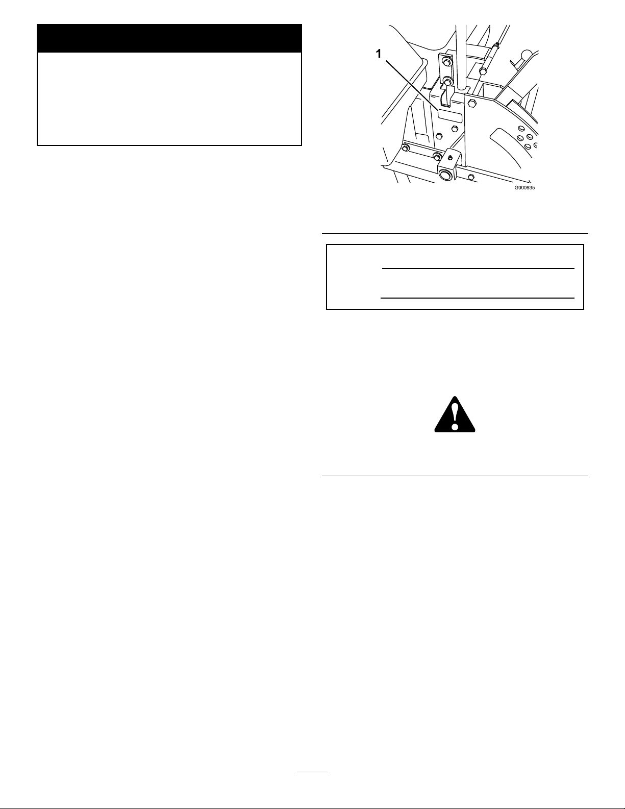
Figure1
1.Modelandserialnumberlocation
Theenclosed
Engine Owner’ s Man ual
issupplied
forinformationregardingtheUSEnvironmental
ProtectionAgency(EPA)andtheCalifornia
EmissionControlRegulationofemissionsystems,
maintenance,andwarranty.Replacementsmaybe
orderedthroughtheenginemanufacturer.
Introduction
Thisrotary-blade,ridinglawnmowerisintendedto
beusedbyresidentialhomeownersorprofessional,
hiredoperators.Itisdesignedprimarilyforcutting
grassonwell-maintainedlawnsonresidential
orcommercialproperties.Itisnotdesignedfor
cuttingbrushorforagriculturaluses.
Readthisinformationcarefullytolearnhowtooperate
andmaintainyourproductproperlyandtoavoidinjury
andproductdamage.Youareresponsibleforoperating
theproductproperlyandsafely.
YoumaycontactTorodirectlyatwww.Toro.comfor
productandaccessoryinformation,helpndinga
dealer,ortoregisteryourproduct.
Wheneveryouneedservice,genuineT oroparts,or
additionalinformation,contactanAuthorizedService
DealerorToroCustomerServiceandhavethemodel
andserialnumbersofyourproductready.
identiesthelocationofthemodelandserialnumbers
ontheproduct.Writethenumbersinthespace
provided.
Figure1
ModelNo.
SerialNo.
Thismanualidentiespotentialhazardsandhas
safetymessagesidentiedbythesafetyalertsymbol
(Figure2),whichsignalsahazardthatmaycauseserious
injuryordeathifyoudonotfollowtherecommended
precautions.
Figure2
1.Safetyalertsymbol
Thismanualuses2otherwordstohighlightinformation.
Importantcallsattentiontospecialmechanical
informationandNoteemphasizesgeneralinformation
worthyofspecialattention.
Contents
Introduction.................................................................2
Safety...........................................................................4
SafeOperatingPractices.......................................4
SlopeIndicator.....................................................6
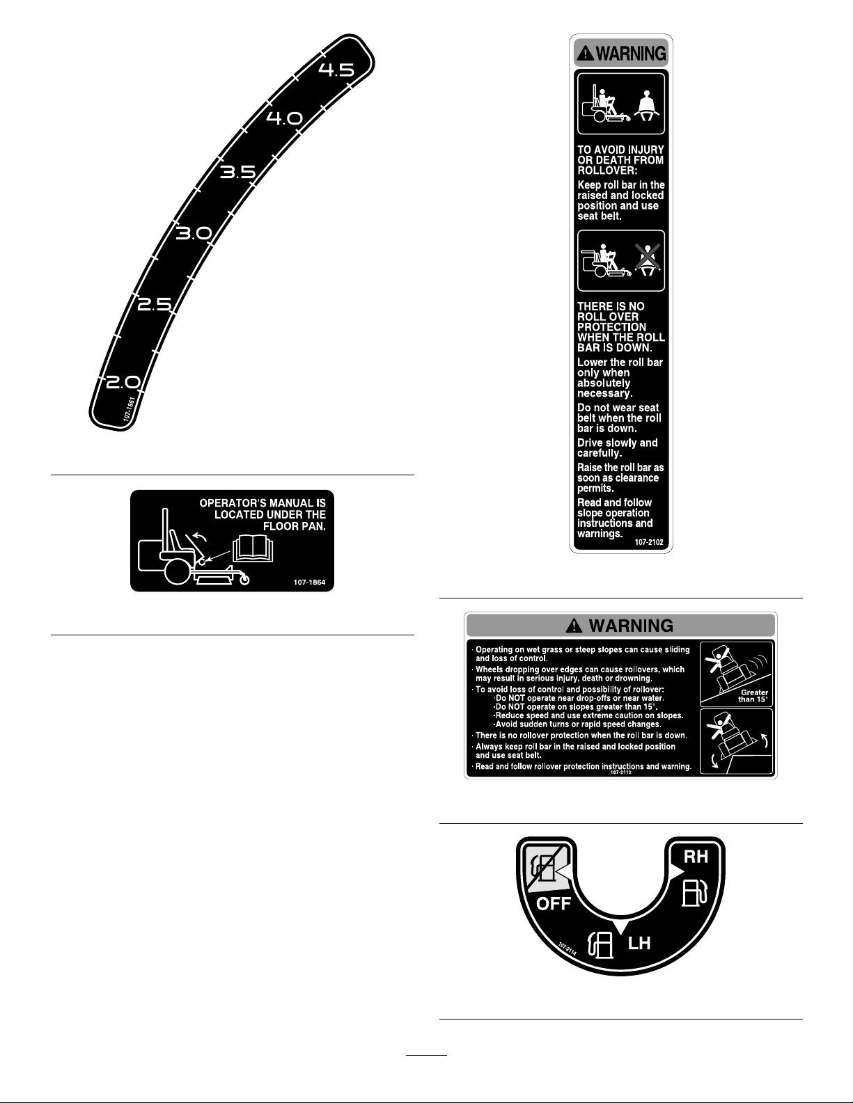
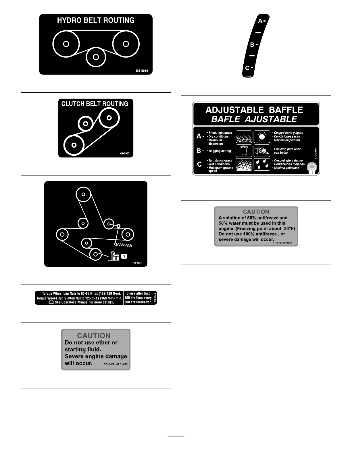
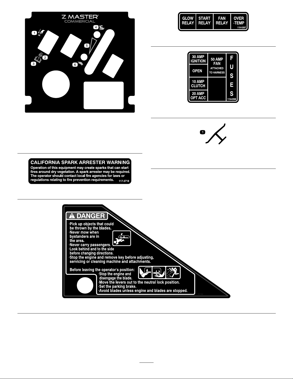
SafetyandInstructionalDecals.............................7
ProductOverview......................................................14
Controls.............................................................14
Operation...................................................................15
AddingFuel.......................................................15
BiodieselReady..................................................16
FillingtheFuelTank...........................................16
©2010—TheT oro®Company
8111LyndaleAvenueSouth
Bloomington,MN55420
Contactusatwww.T oro.com.
2
PrintedintheUSA.
AllRightsReserved
Page 3

CheckingtheEngineOilLevel............................16
SwitchingtheFuelTanks....................................16
UsingtheRolloverProtectionSystem
(ROPS)..........................................................17
ThinkSafetyFirst...............................................18
OperatingtheParkingBrake...............................19
StartingandStoppingtheEngine........................19
OperatingthePowerTakeOff(PTO).................21
TheSafetyInterlockSystem................................21
DrivingForwardorBackward.............................22
StoppingtheMachine.........................................23
AdjustingtheHeight-of-Cut...............................23
AdjustingtheAnti-ScalpRollers.........................23
AdjustingtheFlowBafe...................................24
PositioningtheFlowBafe.................................25
PositioningtheSeat............................................25
UnlatchingtheSeat.............................................26
PushingtheMachinebyHand.............................26
OperatingwiththeOverheatSensor...................27
UsingtheSideDischarge....................................27
TransportingMachines.......................................27
LoadingMachines..............................................28
UsingtheZStand®............................................28
OperatingTips...................................................29
Maintenance...............................................................31
RecommendedMaintenanceSchedule(s)................31
Lubrication.............................................................32
GreasingandLubrication...................................32
GreasingtheMowerDeckandBelt
Idlers..............................................................33
LubricateCasterWheelHubs.............................33
EngineMaintenance...............................................35
ServicingtheAirCleaner....................................35
ServicingtheEngineOil.....................................36
FuelSystemMaintenance.......................................39
ServicingtheFuelFilterandWater
Seperator........................................................39
ServicingtheFuelTank......................................40
ElectricalSystemMaintenance................................41
ServicingtheBattery...........................................41
ServicingtheFuses.............................................42
DriveSystemMaintenance.....................................43
AdjustingtheTracking........................................43
CheckingtheTirePressure.................................44
CheckingtheWheelHubSlottedNut..................44
AdjustingtheCasterPivotBearing......................44
ServicingtheGearBox.......................................45
AdjustingtheElectricClutch..............................45
CoolingSystemMaintenance..................................47
ServicingtheCoolingSystem..............................47
BrakeMaintenance.................................................48
AdjustingtheParkingBrake................................48
BeltMaintenance....................................................49
InspectingtheBelts............................................49
ReplacingtheMowerBelt...................................49
AdjustingtheMowerBeltTensionfor72in
MowersOnly..................................................50
ReplacingthePTODriveBelt.............................50
ReplacingthePumpDriveBelt...........................51
ReplacingandTensioningtheAlternator
Belt................................................................51
ControlsSystemMaintenance.................................53
AdjustingtheControlHandleNeutral
Position..........................................................53
HydraulicSystemMaintenance...............................54
ServicingtheHydraulicSystem...........................54
SettingtheHydraulicPumpNeutral
Position..........................................................56
MowerDeckMaintenance......................................58
LevelingtheMoweratThreePositions................58
ServicingtheCuttingBlades...............................59
ReplacingtheGrassDeector.............................61
Cleaning.................................................................62
CleaningUndertheMower.................................62
WasteDisposal...................................................62
Storage.......................................................................63
CleaningandStorage..........................................63
Troubleshooting.........................................................64
Schematics.................................................................66
3
Page 4

Safety
•Useextracarewhenhandlingdieselandotherfuels.
Theyareammableandvaporsareexplosive.
Improperuseormaintenancebytheoperatororowner
canresultininjury.Toreducethepotentialforinjury,
complywiththesesafetyinstructionsandalwayspay
attentiontothesafetyalertsymbol,whichmeans
CAUTION,WARNING,orDANGER-“personal
safetyinstruction."Failuretocomplywiththe
instructionmayresultinpersonalinjuryordeath.
Thisproductiscapableofamputatinghandsand
feetandthrowingobjects.Alwaysfollowallsafety
instructionstoavoidseriousinjuryordeath.
Thisproductisdesignedforcuttingandrecyclinggrass
or,whenequippedwithagrassbagger,forcatching
cutgrass.Anyuseforpurposesotherthanthesecould
provedangeroustouserandbystanders.
SafeOperatingPractices
ThefollowinginstructionsarefromANSIstandard
B71.4-2004.
Training
•ReadtheOperator’sManualandothertraining
material.Iftheoperator(s)ormechanic(s)cannot
readEnglishitistheowner’sresponsibilitytoexplain
thismaterialtothem.
•Becomefamiliarwiththesafeoperationofthe
equipment,operatorcontrols,andsafetysigns.
•Alloperatorsandmechanicsshouldbetrained.The
ownerisresponsiblefortrainingtheusers.
•Neverletchildrenoruntrainedpeopleoperateor
servicetheequipment.Localregulationsmayrestrict
theageoftheoperator.
•Theowner/usercanpreventandisresponsiblefor
accidentsorinjuriesoccurringtohimselforherself,
otherpeopleorproperty.
–Useonlyanapprovedcontainer
–Neverrefuelordrainthemachineindoors.
–Neverremovefuelcaporaddfuelwithengine
running.Allowenginetocoolbeforerefueling.
Donotsmoke.
•Checkthatoperator’spresencecontrols,safety
switchesandshieldsareattachedandfunctioning
properly.Donotoperateunlesstheyarefunctioning
properly.
Operation
•Lightningcancausesevereinjuryordeath.If
lightningisseenorthunderisheardinthearea,do
notoperatethemachine;seekshelter.
•Neverrunanengineinanenclosedarea.
•Onlyoperateingoodlight,keepingawayfromholes
andhiddenhazards.
•Besurealldrivesareinneutralandparkingbrakeis
engagedbeforestartingengine.Starttheengineonly
fromtheoperator’sposition.Useseatbelts.
•Neverraisemowerwiththebladesrunning.
•NeveroperatewithoutthePTOshield,orother
guardssecurelyinplace.Besureallinterlocksare
attached,adjustedproperly,andfunctioningproperly .
•Neveroperatewiththedischargedeectorraised,
removedoraltered,unlessusingagrasscatcher.
•Donotchangetheenginegovernorsettingor
overspeedtheengine.
•Stoponlevelground,lowerimplements,disengage
drives,engageparkingbrake,shutoffenginebefore
leavingtheoperator’ spositionforanyreason
includingemptyingthecatchersoruncloggingthe
chute.
Preparation
•Evaluatetheterraintodeterminewhataccessories
andattachmentsareneededtoproperlyand
safelyperformthejob.Onlyuseaccessoriesand
attachmentsapprovedbythemanufacturer.
•Wearappropriateclothingincludinghardhat,safety
glassesandhearingprotection.Longhair,loose
clothingorjewelrymaygettangledinmovingparts.
•Inspecttheareawheretheequipmentistobeused
andremoveallobjectssuchasrocks,toysandwire
whichcanbethrownbythemachine.
•Stopequipmentandinspectbladesafterstriking
objectsorifanabnormalvibrationoccurs.Make
necessaryrepairsbeforeresumingoperations.
•Keephandsandfeetawayfromthecuttingunits.
•Nevercarrypassengersandkeeppetsandbystanders
away.
•Bealert,slowdownandusecautionwhenmaking
turns.Lookbehindandtothesidebeforechanging
directions.
•Slowdownandusecautionwhencrossingroadsand
sidewalks.Stopbladesifnotmowing.
4
Page 5

•Beawareofthemowerdischargedirectionanddo
notpointitatanyone.
•Donotoperatethemowerundertheinuenceof
alcoholordrugs.
•Useextremecarewhenloadingorunloadingthe
machineintoatrailerortruck.
•Usecarewhenapproachingblindcorners,shrubs,
trees,orotherobjectsthatmayobscurevision.
SlopeOperation
•Donotmowslopesgreaterthan15degrees.
•Donotmowneardrop-offs,ditches,steepbanks
orwater.Wheelsdroppingoveredgescancause
rollovers,whichmayresultinseriousinjury,death
ordrowning.
•Donotmowslopeswhengrassiswet.Slippery
conditionsreducetractionandcouldcausesliding
andlossofcontrol.
•Donotmakesuddenturnsorrapidspeedchanges.
•Useawalkbehindmowerand/orahandtrimmer
neardrop-offs,ditches,steepbanksorwater.
•Reducespeedanduseextremecautiononslopes.
•Removeormarkobstaclessuchasrocks,treelimbs,
etc.fromthemowingarea.Tallgrasscanhide
obstacles.
•Watchforditches,holes,rocks,dips,andrisesthat
changetheoperatingangle,asroughterraincould
overturnthemachine.
•Avoidsuddenstartswhenmowinguphillbecause
themowermaytipbackwards.
•Beawarethatlossoftractionmayoccurgoing
downhill.Weighttransfertothefrontwheelsmay
causedrivewheelstoslipandcauselossofbraking
andsteering.
•Alwaysavoidsuddenstartingorstoppingona
slope.Iftireslosetraction,disengagethebladesand
proceedslowlyofftheslope.
•Followthemanufacturer’srecommendationsfor
wheelweightsorcounterweightstoimprovestability.
•Useextremecarewithgrasscatchersorother
attachments.Thesecanchangethestabilityofthe
machineandcauselossofcontrol.
UsingtheRolloverProtectionSystem
(ROPS)
•Keeptherollbarintheraisedandlockedposition
andusetheseatbeltwhenoperatingthemachine.
•Becertainthattheseatbeltcanbereleasedquickly
intheeventofanemergency.
•Beawarethereisnorolloverprotectionwhenthe
rollbarisdown.
•Checktheareatobemowedandneverfoldthe
ROPSinareaswherethereareslopes,dropoffsor
water.
•Lowertherollbaronlywhenabsolutelynecessary.
Donotweartheseatbeltwiththerollbarfolded
down.
•Checkcarefullyforoverheadclearances(i.e.
branches,doorways,electricalwires)beforedriving
underanyobjectsanddonotcontactthem.
Maintenanceandstorage
•Disengagedrives,lowerimplement,setparking
brake,stopengineandremovekey .Waitforall
movementtostopbeforeadjusting,cleaningor
repairing.
•Cleangrassanddebrisfromcuttingunits,drives,
mufers,andenginetohelppreventres.Cleanup
oilorfuelspillage.
•Letenginecoolbeforestoringanddonotstorenear
ame.
•Shutofffuelwhilestoringortransporting.Donot
storefuelnearamesordrainindoors.
•Parkmachineonlevelground.Neverallowuntrained
personneltoservicemachine.
•Usejackstandstosupportcomponentswhen
required.
•Carefullyreleasepressurefromcomponentswith
storedenergy.
•Disconnectbatterybeforemakinganyrepairs.
Disconnectthenegativeterminalrstandthe
positivelast.Reconnectpositiverstandnegative
last.
•Usecarewhencheckingblades.Wraptheblade(s)or
weargloves,andusecautionwhenservicingthem.
Onlyreplaceblades.Neverstraightenorweldthem.
•Keephandsandfeetawayfrommovingparts.If
possible,donotmakeadjustmentswiththeengine
running.
•Chargebatteriesinanopenwellventilatedarea,
awayfromsparkandames.Unplugchargerbefore
connectingordisconnectingfrombattery.W ear
protectiveclothinganduseinsulatedtools.
•Keepallpartsingoodworkingconditionandall
hardwaretightened.Replaceallwornordamaged
decals.
•UseonlyToroapprovedattachments.Warrantymay
bevoidedifusedwithunapprovedattachments.
5
Page 6
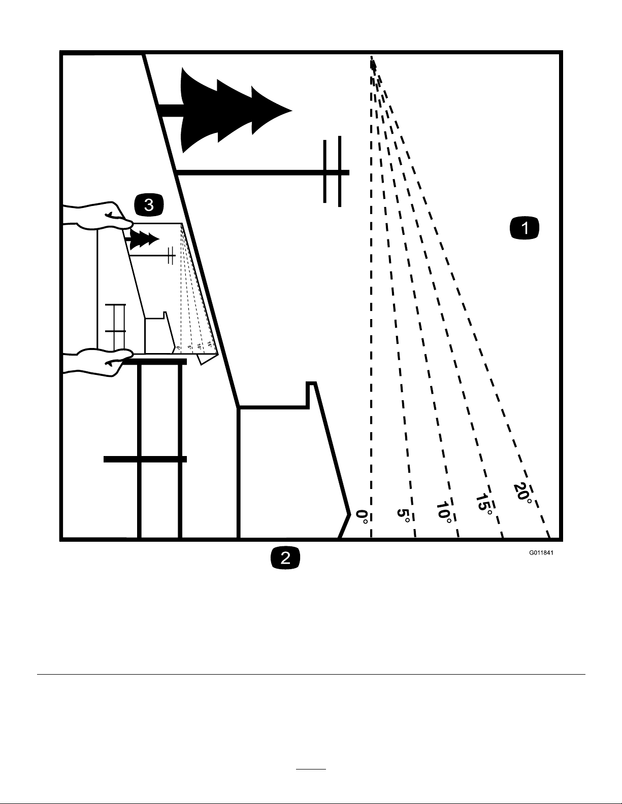
SlopeIndicator
G011841
Figure3
Thispagemaybecopiedforpersonaluse.
1.Themaximumslopeyoucansafelyoperatethemachineonis15degrees.Usetheslopecharttodeterminethedegreeofslope
ofhillsbeforeoperating.Donotoperatethismachineonaslopegreaterthan15degrees.Foldalongtheappropriateline
tomatchtherecommendedslope.
2.Alignthisedgewithaverticalsurface,atree,building,fencepole,etc.
3.Exampleofhowtocompareslopewithfoldededge.
6
Page 7

SafetyandInstructional
Decals
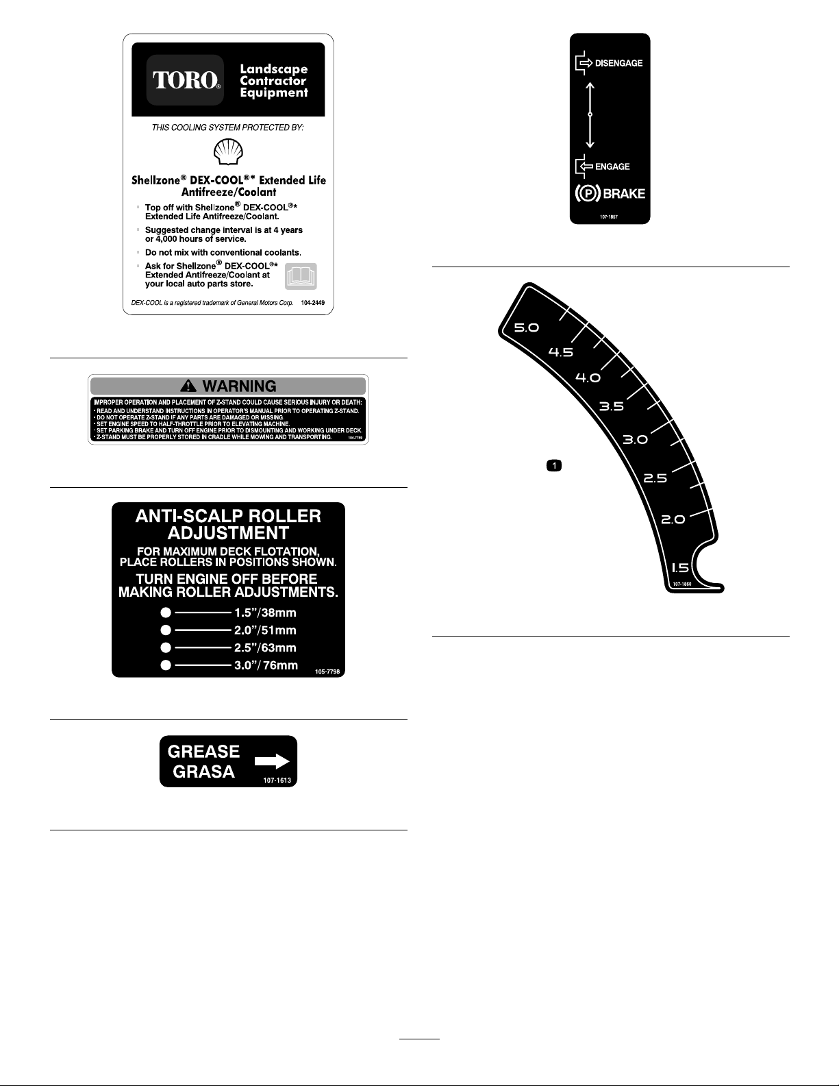
Safetydecalsandinstructionsareeasilyvisibletotheoperatorandarelocatednearanyareaof
potentialdanger.Replaceanydecalthatisdamagedorlost.
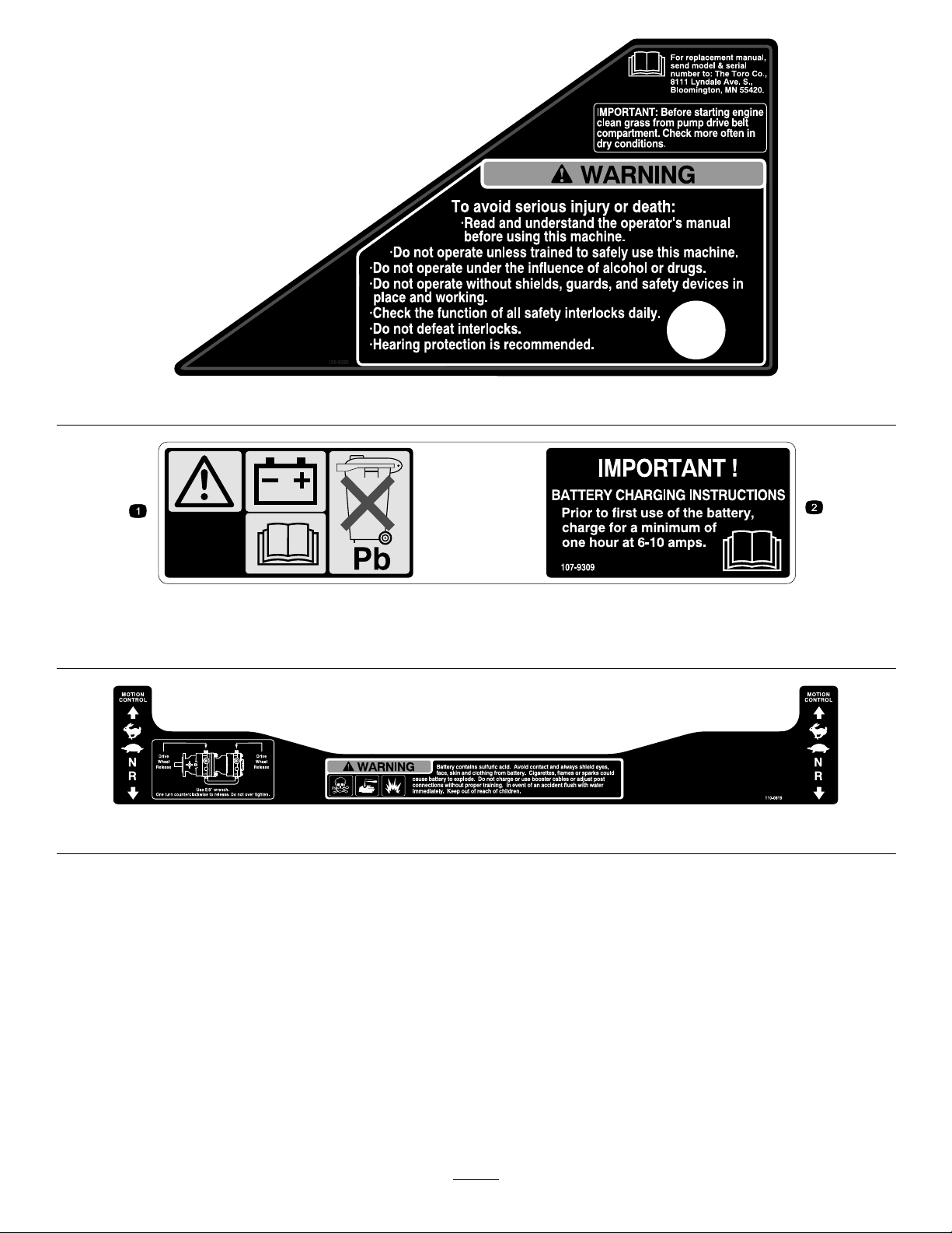
65-2690
1-403005
66-1340
1-643253
68-8340
54-9220
1.Warning—wearhearingprotection.
98-4387
98-5954
58-6520
1.Grease
7
Page 8
107-1857
104-2449
104-7759
107-1860
105-7798
107-1613
8
Page 9
107-1861
107-2102
107-1864
107-2112
107-2114
9
Page 10
108-5955
110-2067
108-5957
110-2068
1.ReadtheOperator’sManual.
110–3842
108-5981
109-7949
110–0806
10
Page 11
1.Interval
2.PowerT ake-off(PTO)
3.Parkingbrake
4.Neutral
5.Operatorpresenceswitch
6.Battery
112-8651
110-3851
1.Removetheignitionkeyandreadtheinstructionsbefore
servicingorperformingmaintenance.
110-3852
1.Removetheignitionkey
andreadtheinstructions
beforeservicingor
performingmaintenance.
2.Continuoustonesignals
theuserthatengineis
overheating.
114-9600
1.ReadtheOperator’sManual.
115-4212
1.Hydraulicoillevel3.Warning—donottouch
thehotsurface.
2.ReadtheOperator’s
Manual.
1.Cutting/dismemberment
hazard,fanand
entanglementhazard,
belt.
110-3853
2.Removetheignitionkey
andreadtheinstructions
beforeservicingor
performingmaintenance.
11
Page 12
117-0912
1.Pushtoengage4.Fast
2.Engine—preheat
3.ReartheOperator’s
Manual.
119-0397
119-0398
5.Continuousvariable
setting
6.Slow
Manufacturer’sMark
1.Indicatesthebladeisidentiedasapartfromtheoriginal
machinemanufacturer.
117–2718
106-7492
12
Page 13
106-9989
107-9309
1.Warning—readtheOperator’sManualforinformationonchargingthebattery;containslead;donotdiscard.
2.ReadtheOperator’sManual.
110-0819
13
Page 14
ProductOverview
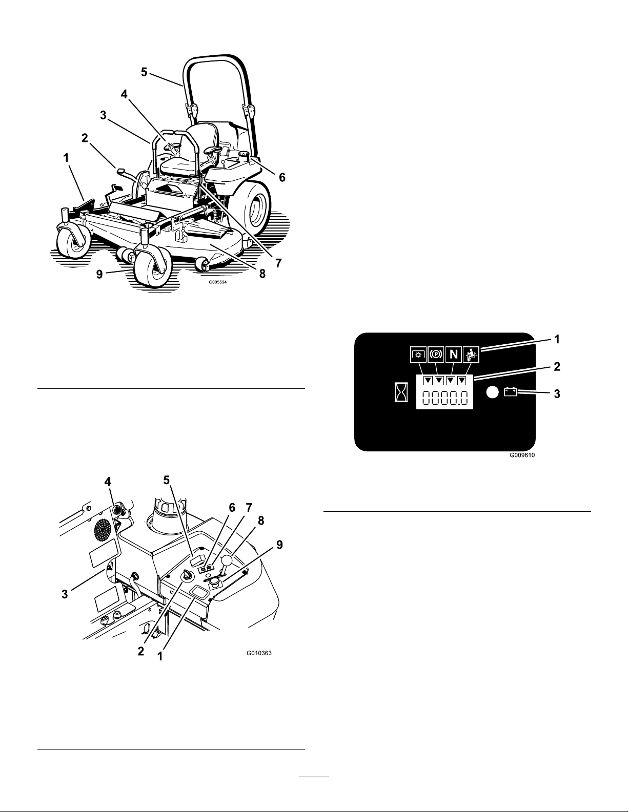
Figure4
1.ZStand
2.Height-of-cutlever
3.Motioncontrollever8.Mowerdeck
4.Seatbelt9.Casterwheel
5.Rollbar
©
6.Fuelcap(bothsides)
7.Parkingbrakelever
HourMeter
Thehourmeterrecordsthenumberofhourstheengine
hasoperated.Itoperateswhentheengineisrunning.
Usethesetimesforschedulingregularmaintenance
Figure5).
(
SafetyInterlockIndicators
Therearesymbolsonthehourmeterandtheyindicate
withablacktrianglethattheinterlockcomponentisin
thecorrectposition(
Figure6).
BatteryIndicatorLight
WhentheignitionkeyisinitiallyturnedtotheRun
positionforafewseconds,thebatteryvoltagewillbe
displayedintheareawherethehoursarenormally
displayed.
Thebatterylightturnsonwhentheignitionisturned
onandwhenthechargeisbelowthecorrectoperating
Figure6).
level(
Controls
Becomefamiliarwithallthecontrolsbeforeyoustartthe
engineandoperatethemachine(Figure4andFigure5).
Figure5
1.Hourmeter
2.Ignitionswitch7.EngineTemperaturelight
3.Fuelselectorvalve8.Throttlecontrol
4.Audiblealarm
5.Glowplugswitch
6.Glowpluglight
9.PTOSwitch
Figure6
1.Safetyinterlocksymbols
2.Hourmeter
3.Batterylight
ThrottleControl
ThethrottlecontrolisvariablebetweenFastandSlow.
BladeControlSwitch(PTO)
Thebladecontrolswitch(PTO)isusedtoengagethe
electricclutchtodrivethemowerbladeswiththemotion
controlleversinthecenter,un-lockedposition.Pullthe
switchuptoengagethebladesandrelease.Todisengage
theblades,pushthebladecontrolswitch(PTO)down.
NeutralLockPosition
Theneutrallockpositionisusedwiththesafetyinterlock
systemandtodetermineneutralposition.
14
Page 15

IgnitionSwitch
Thisswitchisusedtostartthemowerengineandhas
threepositions:Start,RunandOff.
GlowPlugLight
Theglowplugindicatorlightturnsonwhentheglow
plugbuttonisengaged(
Figure5).
GlowPlugSwitch
Thisswitchactivatestheglowplugsandisindicatedby
theglowpluglight.Holddowntheglowplugswitchfor
10secondspriortostarting.
TemperatureLight
Thetemperaturelightcomesonwhentheengineisover
heating(Figure5).
Operation
Note:Determinetheleftandrightsidesofthe
machinefromthenormaloperatingposition.
AddingFuel
Theenginerunsonclean,freshdieselfuelwith
aminimumoctaneratingof40.Purchasefuelin
quantitiesthatcanbeusedwithin30daystoensure
fuelfreshness.
Usesummergradedieselfuel(No.2-D)attemperatures
above20°F(-7°C)andwintergradedieselfuel(No.
1-DorNo.1-D/2-Dblend)below20°F(-7°C).Useof
wintergradedieselfuelatlowertemperaturesprovides
lowerashpointandpourpointcharacteristics,
thereforeeasingstartabilityandlesseningchances
ofchemicalseparationofthefuelduetolower
temperatures(waxappearance,whichmaypluglters).
AudibleAlarm
Thismachinehasanaudiblealarmthatalertstheuser
toturnofftheengineorenginedamagecanoccurfrom
overheating.RefertoServicingtheCoolingSystemin
CoolingSystemMaintenance(page47).
FuelSelectorValve
Thefuelselectorvalveislocatedbehindtheseat.
Closethefuelselectorvalvewhentransportingor
storingmower.
Movetheselectorvalvetothelefthand(LH)or
righthand(RH)positionforoperation.
Attachments/Accessories
AselectionofToroapprovedattachmentsand
accessoriesareavailableforusewiththemachineto
enhanceandexpanditscapabilities.Contactyour
AuthorizedServiceDealerorDistributororgoto
www.Toro.comforalistofallapprovedattachments
andaccessories.
Useofsummergradedieselfuelabove20°F(-7°C)will
contributetowardlongerlifeofthepumpcomponents.
Important:Donotusekeroseneorgasoline
insteadofdieselfuel.Failuretoobservethis
cautionwilldamagetheengine.
WARNING
Fuelisharmfulorfatalifswallowed.Long-term
exposuretovaporscancauseseriousinjuryand
illness.
•Avoidprolongedbreathingofvapors.
•Keepfaceawayfromnozzleandgastankor
conditioneropening .
•Keepgasawayfromeyesandskin.
15
Page 16

DANGER
Incertainconditions,fuelisextremelyammable
andhighlyexplosive.Areorexplosionfromfuel
canburnyouandothersandcandamageproperty.
•Fillthefueltankoutdoorsonlevelground,in
anopenarea,whentheengineiscold.Wipe
upanyfuelthatspills.
•Neverllthefueltankinsideanenclosedtrailer.
•Donotllthefueltankcompletelyfull.Fill
thefueltanktothebottomofthellerneck.
Theemptyspaceinthetankallowsgasolineto
expand.Overllingmayresultinfuelleakage
ordamagetotheengineoremissionsystem(if
equipped).
•Neversmokewhenhandlingfuel,andstay
awayfromanopenameorwherefuelfumes
maybeignitedbyaspark.
•Paintedsurfacesmaybedamagedbybiodiesel
blends.
•UseB5(biodieselcontendof5%)orlesserblend
incoldweather.
•Monitorseals,hoses,gasketsincontactwithfuelas
theymaybedegradeovertime.
•Fuellterpluggingmaybeexpectedforatimeafter
convertingtobiodieselblends.
•Contactyourdistributorifyouwishformore
informationonbiodiesel.
FillingtheFuelTank
Note:Donotllthefueltankcompletelyfull.Fillthe
fueltanktothebottomofthellerneck.Theempty
spaceinthetankallowsthegasolinetoexpand.
1.Shuttheengineoffandsettheparkingbrake.
•Storefuelinanapprovedcontainerandkeepit
outofthereachofchildren.Neverbuymore
thana30-daysupplyoffuel.
•Alwaysplacefuelcontainersontheground
awayfromyourvehiclebeforelling.
•Donotllfuelcontainersinsideavehicleoron
atruckortrailerbedbecauseinteriorcarpets
orplastictruckbedlinersmayinsulatethe
containerandslowthelossofanystaticcharge.
•Whenpractical,removegas-powered
equipmentfromthetruckortrailerandrefuel
theequipmentwithitswheelsontheground.
•Ifthisisnotpossible,thenrefuelsuch
equipmentonatruckortrailerfromaportable
container,ratherthanfromafueldispenser
nozzle.
•Ifafueldispensernozzlemustbeused,keep
thenozzleincontactwiththerimofthefuel
tankorcontaineropeningatalltimesuntil
fuelingiscomplete.
2.Cleanaroundeachfueltankcapandremovethe
cap.Fillthefueltanktothebottomoftheller
neck.Thisspaceinthetankallowsthefuelto
expand.Donotllthefueltankcompletelyfull.
3.Installthefueltankcapsecurely .Wipeupanyfuel
thatmayhavespilled.
4.Ifpossible,llthefueltankaftereachuse.Thiswill
minimizepossiblebuildupofcondensationinside
thefueltank.
CheckingtheEngineOilLevel
Beforeyoustarttheengineandusethemachine,check
theoillevelintheenginecrankcase;refertoChecking
OilLevelinEngineMaintenance(page35)
SwitchingtheFuelTanks
Important:Donotrunthemachineoutoffuel.
Thefuelselectorvalveislocatedbehindtheleftside
oftheseat.
BiodieselReady
Thismachinecanalsouseabiodieselblendedfuel
ofuptoB20(20%biodiesel,80%petrodiesel).The
petrodieselportionshouldbeloworultralowsulfur.
Observethefollowingprecautions:
•Thebiodieselportionofthefuelmeetspecication
ASTMD6751orEN14214.
•TheblendedfuelcompositionshouldmeetASTM
D975orEN590.
Theunithastwofueltanks.Onetankisontheleft
sideandoneontherightside.Eachtankconnectsto
thefuelselectorvalve.Fromthereacommonfuelline
leadstotheengine(Figure7).
Tousetheleftsidefueltankrotatethefuelselector
valvetotheLH,lefthandlocation.Tousetheright
sidefueltankrotatethefuelselectorvalvetotheRH,
righthandlocation(Figure7)
Closethefuelselectorvalvebeforetransportingor
storingmachine.
16
Page 17
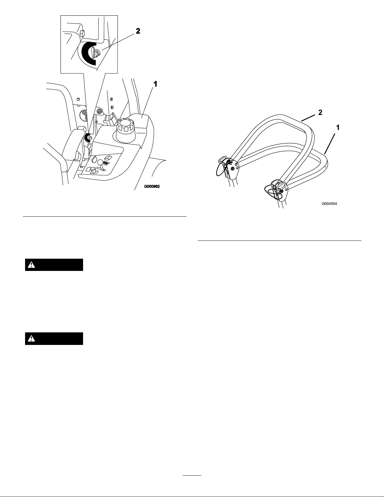
1.Leftsidefueltank
UsingtheRolloverProtection
Figure7
2.Fuelselectorvalve
Important:Lowertherollbaronlywhen
absolutelynecessary.
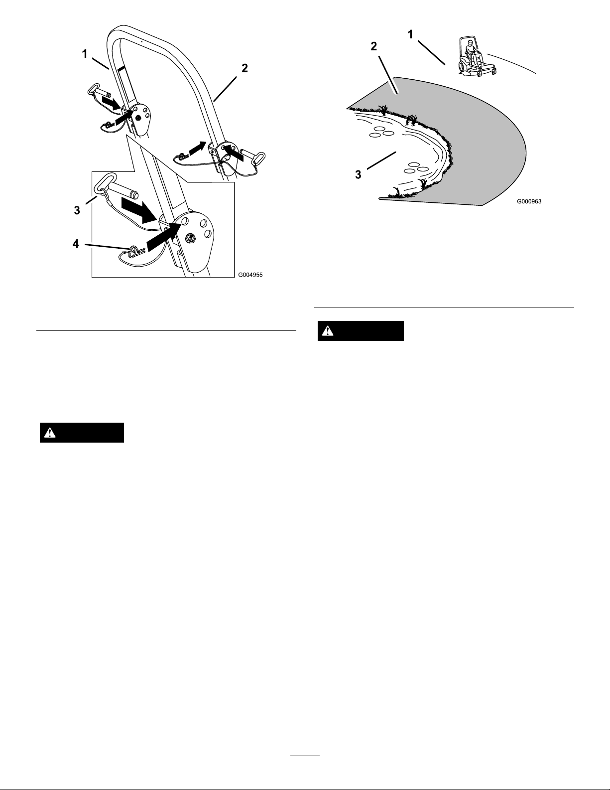
1.Removethehairpincotterpinsandremovethetwo
Figure9).
pins(
2.Lowerthetherollbartothedownposition.There
aretwodownpositions.SeeFigure8forthe
positions.
3.Installthetwopinsandsecurethemwiththe
hairpincotterpins(
1.Fulldownposition2.Downpositionwithbagger
Figure9).
Figure8
installed
System(ROPS)
WARNING
Toavoidinjuryordeathfromrollover:keepthe
rollbarintheraisedlockedpositionandusethe
seatbelt.
Ensurethattherearpartoftheseatissecuredwith
theseatlatch.
WARNING
Thereisnorolloverprotectionwhentherollbar
isinthedownposition.
•Lowertherollbaronlywhenabsolutely
necessary.
•Donotweartheseatbeltwhentherollbaris
inthedownposition.
•Driveslowlyandcarefully.
•Raisetherollbarassoonasclearancepermits.
Important:Ensurethattherearpartofthe
seatissecuredwiththeseatlatch.
4.Toraisetherollbar,removethehairpincotterpins
andremovethetwopins(Figure9).
5.Raisetherollbartotheuprightpositionandinstall
thetwopinsandsecurethemwiththehairpincotter
Figure9).
pins(
Important:Alwaysusetheseatbeltwiththe
rollbarintheraisedposition.
•Checkcarefullyforoverheadclearances(i.e.
branches,doorways,electricalwires)before
drivingunderanyobjectsanddonotcontact
them.
17
Page 18
G004955
1
2
3
4
Figure9
1.Rollbar3.Pin
2.Raisedposition4.Hairpincotterpin
ThinkSafetyFirst
Pleasereadallsafetyinstructionsandsymbolsinthe
safetysection.Knowingthisinformationcouldhelp
youorbystandersavoidinjury.
Figure10
1.SafeZone-usethe
ZMasterhereonslopes
lessthan15degreesor
atareas.
2.Usewalkbehindmower
and/orhandtrimmernear
drop-offsandwater.
3.Water
CAUTION
Thismachineproducessoundlevelsinexcessof
85dBAattheoperatorsearandcancausehearing
lossthroughextendedperiodsofexposure.
Wearhearingprotectionwhenoperatingthis
machine.
DANGER
Operatingonwetgrassorsteepslopescancause
Theuseofprotectiveequipmentforeyes,ears,feetand
headisrecommended.
slidingandlossofcontrol.
Wheelsdroppingoveredgescancauserollovers,
whichmayresultinseriousinjury,deathor
drowning.
Thereisnorolloverprotectionwhentherollbar
isdown.
Alwayskeeptherollbarintheraisedandlocked
positionandusetheseatbelt.
Readandfollowtherolloverprotectioninstructions
andwarnings.
Toavoidlossofcontrolandpossibilityofrollover:
•Donotoperateneardrop-offsornearwater.
•Donotoperateonslopesgreaterthan
15degrees.
•Reducespeedanduseextremecautionon
slopes.
•Avoidsuddenturnsorrapidspeedchanges.
18
Page 19
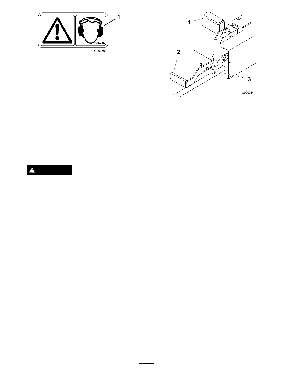
Figure11
1.Warning—wearhearingprotection
OperatingtheParkingBrake
Alwayssettheparkingbrakewhenyoustopthe
machineorleaveitunattended.
SettingtheParkingBrake
1.Movethemotioncontrollevers(Figure18)outto
theneutrallockposition.
2.Pullupandbackontheparkingbrakelevertoset
theparkingbrake(Figure12).Theparkingbrake
levershouldstayrmlyintheengagedposition.
WARNING
Parkingbrakemaynotholdmachineparked
onaslopeandcouldcausepersonalinjuryor
propertydamage.
Donotparkonslopesunlesswheelsare
chockedorblocked
ReleasingtheParkingBrake
Pushforwardanddownontheparkingbrakelever
toreleasetheparkingbrake(Figure12).Theparking
brakeisdisengagedandtheleverwillrestagainstthe
brakestop.
Figure12
1.Parkingbrake-ON3.BrakeStop
2.Parkingbrake-OFF
StartingandStoppingthe
Engine
StartingtheEngineinNormalWeather
1.RaisetheROPSupandlockintoplace,sitonthe
seatandfastentheseatbelt.
2.Movethemotioncontrolstotheneutrallocked
position.
3.Settheparkingbrake;refertoSettingtheParking
Brake.
4.MovethePTO(powertakeoff)switchtotheoff
position(
5.Movethethrottlelevertothemiddleposition
(Figure15).
6.Turntheignitionkeyclockwisetotherunposition
Figure14).
(
Figure13).
7.Pushtheglowplugswitchfor10seconds.Thelight
willturnon.
8.Releasetheswitchafter10seconds.Thelightwill
turnoff.
19
Page 20
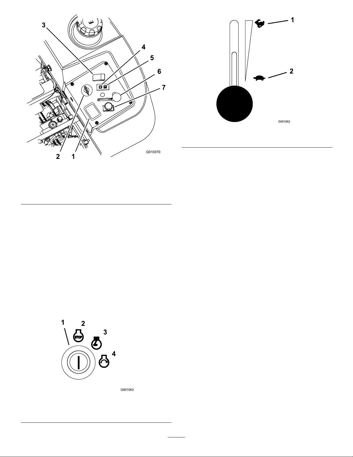
Figure15
1.Throttle—fast
2.Throttle—slow
Figure13
1.Hourmeter5.EngineTemperaturelight
2.Ignitionswitch6.Throttlecontrol
3.Glowplugswitch7.PTOSwitch
4.Glowpluglight
9.Turnthekeytothestartpositionandtheglowplug
indicatorlightwillcomebackon.Whentheengine
starts,releasethekey(Figure14).
Important:Usestartingcyclesofnomorethan
30secondsperminutetoavoidoverheatingthe
startermotor.
10.Iftheenginedoesnotstartimmediately,movethe
throttlecontroltofastandturnthekeytothestart
position.
Note:Additionalstartingcyclesmayberequired
whenstartingtheengineforthersttimeafterthe
fuelsystemhasbeencompletelywithoutfuel.
StartingtheEngineinColdWeather
(Below23°For-5°C)
Usethecorrectengineoilforthestarting
temperature.RefertoServicingtheEngineOilin
EngineMaintenance(page35).
1.StarttheenginewiththethrottleintheFast
position.
2.Turntheignitionkeyclockwisetotherunposition
(Figure14).
3.Pushtheglowplugswitchfor10to15seconds.
Thelightwillturnon.
4.Releasetheswitchafter10to15seconds.Thelight
willturnoff.
5.Turnthekeytothestartpositionandtheglowplug
indicatorlightwillcomebackon.Whentheengine
starts,releasethekey .
Important:Usestartingcyclesofnomorethan
30secondsperminutetoavoidoverheatingthe
startermotor.
Figure14
1.Ignitionswitch3.Run
2.Off4.Start
Note:Donotusefuelleftoverfromthesummer.
Useonlyfreshwintergradedieselfuel.
StoppingtheEngine
1.DisengagethePTO,movethemotioncontrollevers
totheneutrallockedpositionandsettheparking
brake(Figure16).
2.Movethethrottlelevermidwaybetweentheslow
andfastpositions(Figure15).
3.Lettheengineidlefor60seconds.
20
Page 21
4.Turntheignitionkeytotheoffposition(Figure14).
Waitforallmovingpartstostopbeforeleavingthe
operatingposition.
5.Removethekeytopreventpossibilityofsomeone
accidentallystartingthemachinebeforetransporting
orstoringmachine.
6.Closethefuelselectorvalvebeforetransportingor
storingthemachine.
Important:Makesurethatthefuelselector
valveisclosedbeforetransportingorstoring
themachine,asfuelleakagemayoccur.Setthe
parkingbrakebeforetransporting.
Important:Makesuretoremovethekeyas
thefuelpumpmayrunandcausethebattery
tolosecharge.
CAUTION
Childrenorbystandersmaybeinjuredifthey
moveorattempttooperatethetractorwhileit
isunattended.
Alwaysremovetheignitionkeyandsetthe
parkingbrakewhenleavingthemachine
unattended,evenifjustforafewminutes.
OperatingthePowerTakeOff
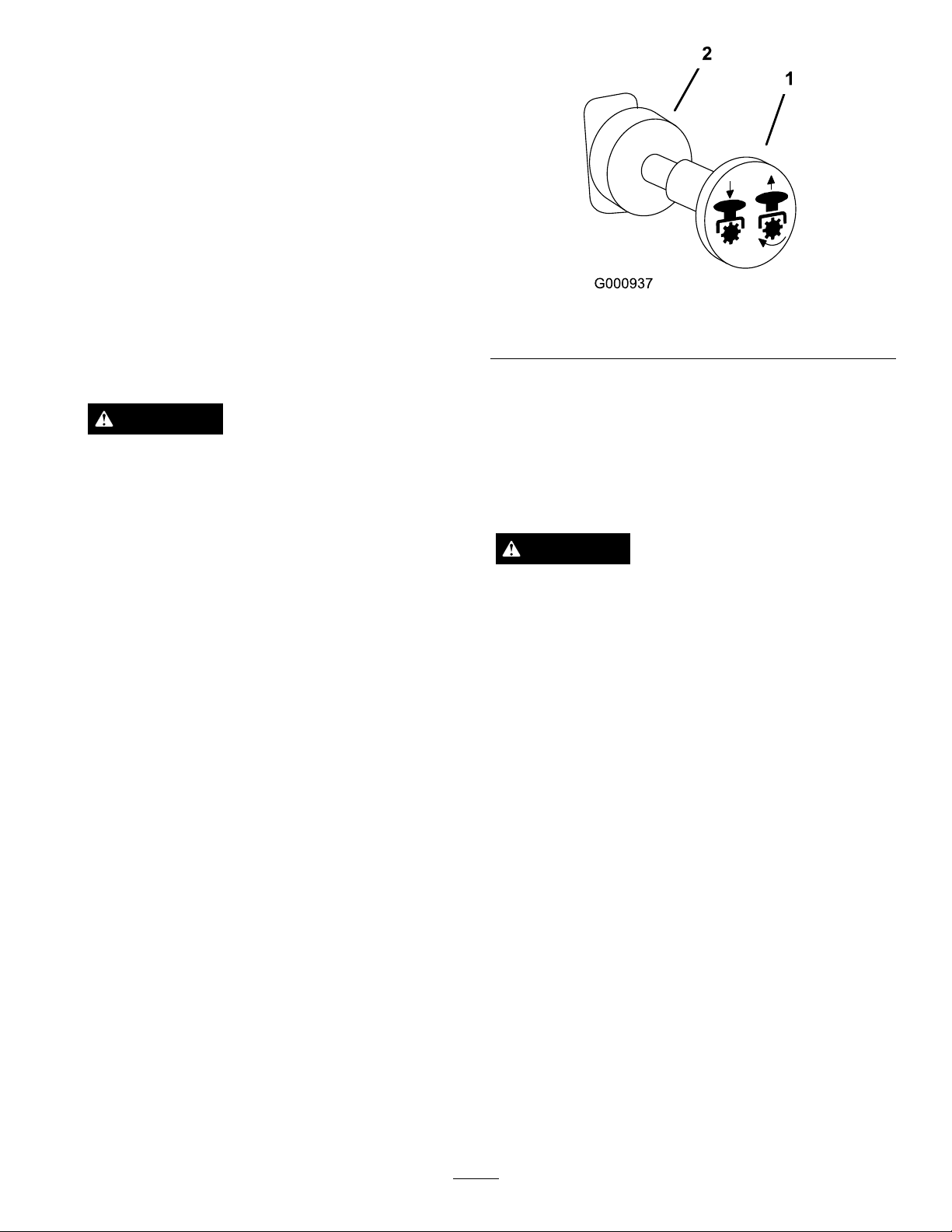
Figure16
1.PTO-On2.PTO-Off
DisengagingthePTO
Todisengage,pushthePTOswitchtotheoffposition
(Figure16).
TheSafetyInterlockSystem
CAUTION
Ifsafetyinterlockswitchesaredisconnectedor
damagedthemachinecouldoperateunexpectedly
causingpersonalinjury.
(PTO)
Thepowertakeoff(PTO)switchstartsandstopsthe
mowerbladesandanypoweredattachments.
EngagingthePTO
1.Iftheengineiscold,allowtheenginetowarmup5
to10minutesbeforeengagingthePTO.
2.Whileseatedintheseat,releasethepressureonthe
tractioncontrolleversandplaceinneutral.
3.Placethethrottleinthefastposition.
Note:EngagingthePTOwiththethrottleatthe
halforlesspositionwillcauseexcessiveweartothe
drivebelts.
4.Pulloutonthepowertakeoff(PTO)switchto
engageit(Figure16).
•Donottamperwiththeinterlockswitches.
•Checktheoperationoftheinterlockswitches
dailyandreplaceanydamagedswitchesbefore
operatingthemachine.
UnderstandingtheSafetyInterlock
System
Thesafetyinterlocksystemisdesignedtopreventthe
enginefromstartingunless:
•Theparkingbrakeisengaged.
•Thepowertakeoff(PTO)isdisengaged.
•Themotioncontrolleversareintheneutrallocked
position
Thesafetyinterlocksystemalsoisdesignedtostopthe
enginewhenthetractioncontrolsaremovedfromthe
lockedpositionwiththeparkingbrakeengagedorif
yourisefromtheseatwhenthePTOisengaged.
Thehourmeterhassymbolstonotifytheuserwhenthe
interlockcomponentisinthecorrectposition.When
thecomponentisinthecorrectposition,atrianglewill
lightupinthecorrespondingsquare.
21
Page 22

CAUTION
Machinecanspinveryrapidly.Operatormaylose
controlofmachineandcausepersonalinjuryor
damagetomachine.
•Usecautionwhenmakingturns.
•Slowthemachinedownbeforemakingsharp
turns.
Figure17
1.Triangleslightupwhentheinterlockcomponentsareinthe
correctposition
TestingtheSafetyInterlockSystem
ServiceInterval:Beforeeachuseordaily
Ifthesafetysystemdoesnotoperateasdescribed
below,haveanAuthorizedServiceDealerrepairthe
safetysystemimmediately .
1.Sittingontheseat,engagetheparkingbrakeand
movethePTOtoon.Trystartingtheengine;the
engineshouldnotcrank.
2.Sittingontheseat,engagetheparkingbrakeand
movethePTOtooff.Moveeithermotioncontrol
lever(outofneutrallockedposition).Trystarting
theengine;theengineshouldnotcrank.Repeatfor
othercontrollever.
3.Sittingontheseat,engagetheparkingbrake,
movethePTOswitchtooffandmovethemotion
controlleverstoneutrallockposition.Nowstart
theengine.Whiletheengineisrunning,release
theparkingbrake,engagethePTOandriseslightly
fromtheseat;theengineshouldstop.
4.Sittingontheseat,engagetheparkingbrake,move
thePTOswitchtooffandmovethemotioncontrol
leverstoneutrallockposition.Nowstarttheengine.
Whiletheengineisrunning,centereithermotion
controlandmove(forwardorreverse);theengine
shouldstop.Repeatforothermotioncontrol.
5.Sittingontheseat,disengagetheparkingbrake,
movethePTOswitchtooffandmovethemotion
controlleverstoneutrallockposition.Trystarting
theengine;theengineshouldnotcrank.
DrivingForward
1.Releasetheparkingbrake;refer
toReleasingtheParkingBrakein
ReleasingtheParkingBrake(page19).
2.Movetheleverstothecenter,un-lockedposition.
3.Togoforward,slowlypushthemotioncontrol
leversforward(Figure18).
Note:Theenginewillkillifthetractioncontrol
leversaremovedwiththeparkingbrakeengaged.
Togostraight,applyequalpressuretobothmotion
controllevers(
Toturn,movethemotioncontrollevertoward
neutralinthedirectionyouwanttoturn(Figure18).
Thefartheryoumovethetractioncontrolleversin
eitherdirection,thefasterthemachinewillmovein
thatdirection.
Tostop,pullthemotioncontrolleverstotheneutral
position.
Figure18).
DrivingForwardorBackward
Thethrottlecontrolregulatestheenginespeedas
measuredinrpm(revolutionsperminute).Place
thethrottlecontrolinthefastpositionforbest
performance.Alwaysoperateinthefullthrottle
positionwhenmowing.
22
Page 23
CAUTION
Childrenorbystandersmaybeinjuredifthey
moveorattempttooperatethetractorwhileitis
unattended.
Alwaysremovetheignitionkeyandsettheparking
brakewhenleavingthemachineunattended,even
ifjustforafewminutes.
AdjustingtheHeight-of-Cut
Theheight-of-cutisadjustedfrom1-1/2to5inch
(38to127mm)in1/4inch(6mm)incrementsby
relocatingthepinintodifferentholelocations.
1.Raisetheheight-of-cutlevertothetransport
position(alsothe5inch(127mm)cuttingheight
position)(
Figure19).
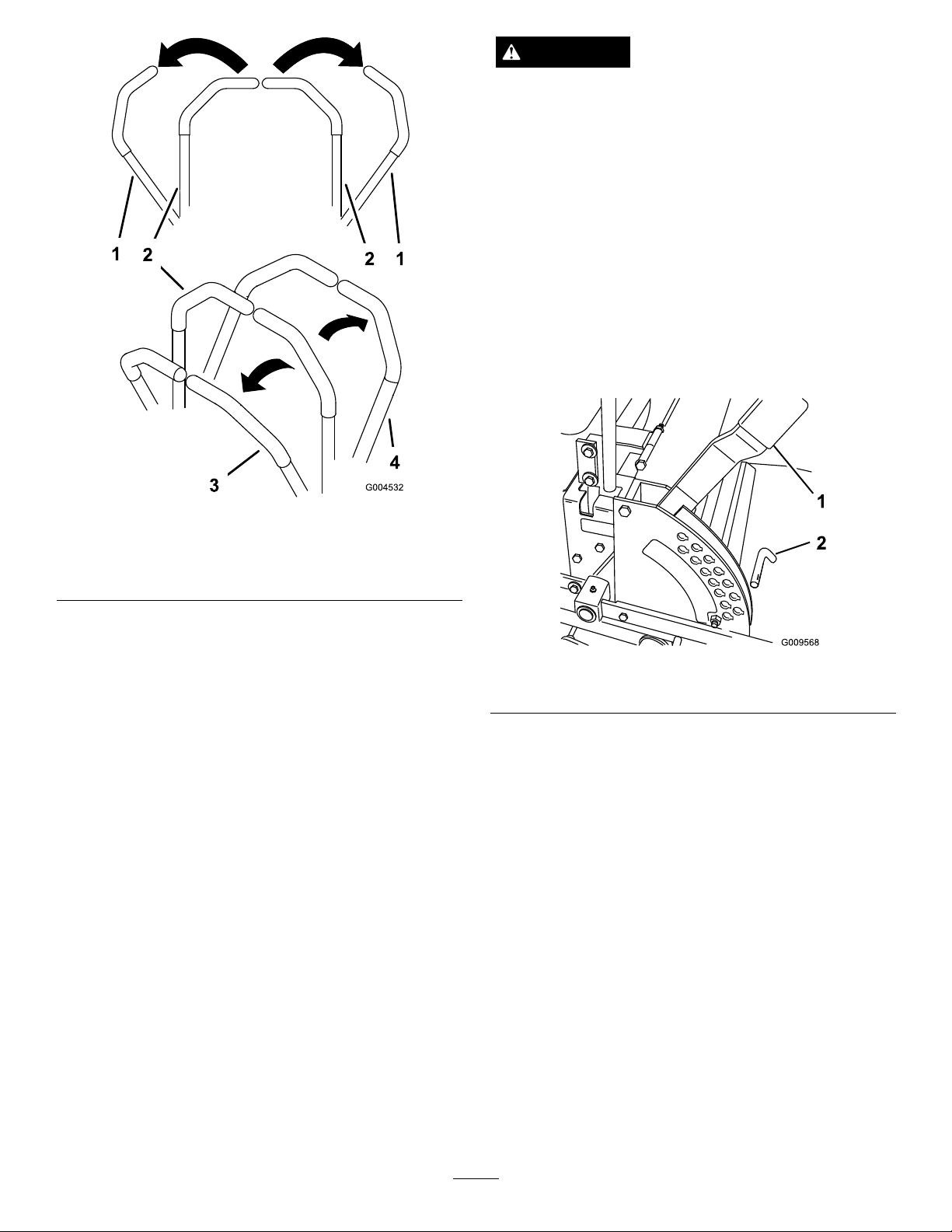
Figure18
1.Motioncontrol
lever-neutrallockposition
2.Centerun-lockposition
3.Forward
4.Backward
DrivingBackward
1.Movetheleverstothecenter,un-lockedposition.
2.Togobackward,slowlypullthemotioncontrol
leversrearward(Figure18).
Togostraight,applyequalpressuretobothmotion
controllevers(
Toturn,releasepressureonthemotioncontrollever
towardthedirectionyouwanttoturn(Figure18).
Tostop,pushthemotioncontrolleverstothe
neutralposition.
Figure18).
StoppingtheMachine
Tostopthemachine,movethetractioncontrollevers
toneutralandmovetolockedposition,disengagethe
powertakeoff(PTO),andturntheignitionkeytooff.
Settheparkingbrakewhenyouleavethe
machine;refertoSettingtheParkingBrakein
SettingtheParkingBrake(page19).Rememberto
removethekeyfromtheignitionswitch.
Figure19
1.Heightofcutlever
2.Toadjust,removethepinfromtheheight-of-cut
bracket(
3.Selectaholeintheheight-of-cutbracket
correspondingtotheheight-of-cutdesiredand,
insertthepin(
4.Movethelevertotheselectedheight.
Figure19).
Figure19).
2.Pin
AdjustingtheAnti-Scalp
Rollers
Wheneveryouchangetheheight-of-cut,itis
recommendedtoadjusttheheightoftheanti-scalp
rollers.
1.DisengagethePTO ,movethemotioncontrol
leverstotheneutrallockedpositionandsetthe
parkingbrake.
2.Stoptheengine,removethekey,andwaitforall
movingpartstostopbeforeleavingtheoperating
position.
23
Page 24
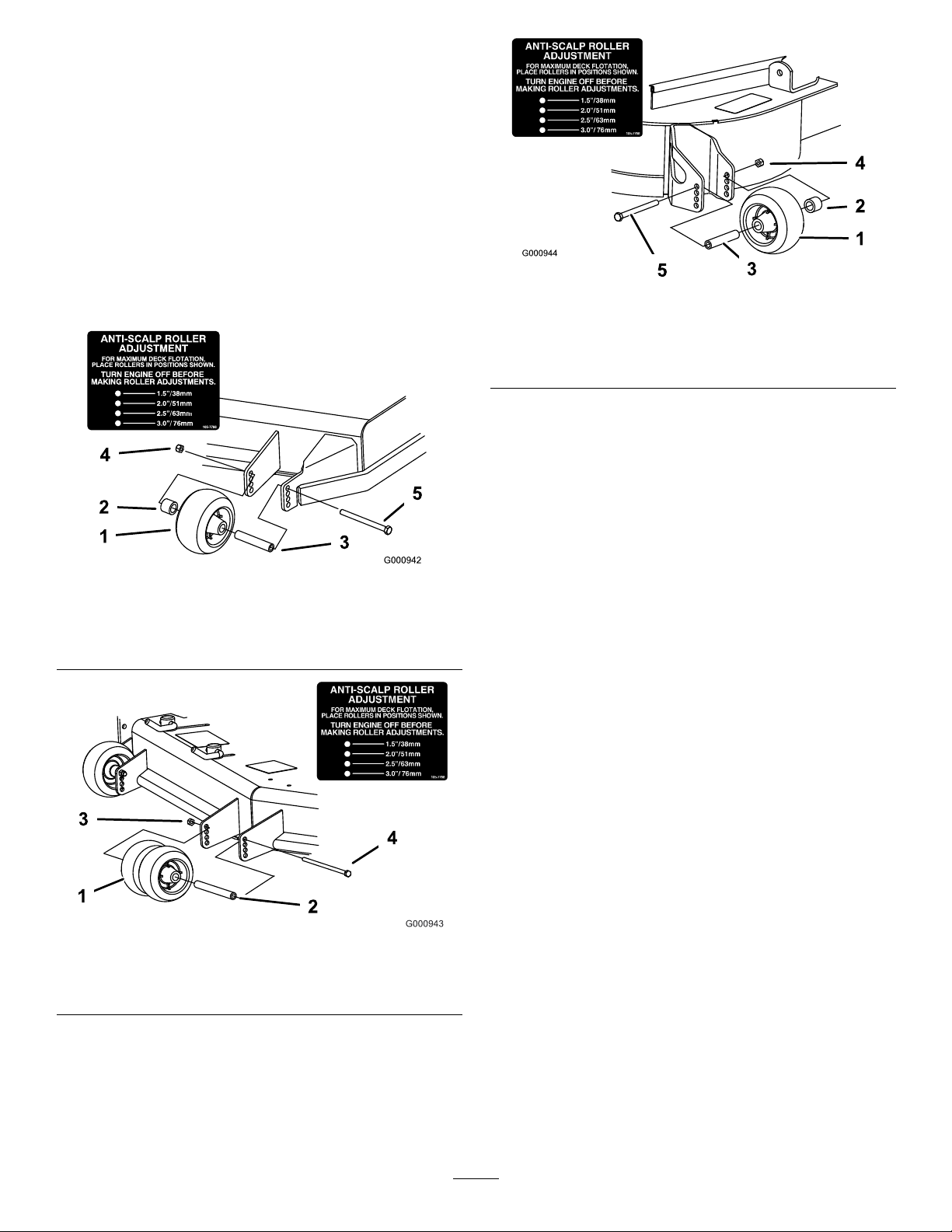
3.Afteradjustingtheheight-of-cut,adjusttherollers
byremovingtheangenut,bushing,spacer,and
bolt(Figure20,Figure21andFigure22).
Note:Thetwomiddlerollerswillnothaveaspacer
Figure21).
(
4.Selectaholesotheanti-scalprollerispositionedto
thenearestcorrespondingheight-of-cutdesired.
5.Installtheangenutbushing,spacer,andbolt.
Torqueto40-45ft-lb(54-61N-m)(Figure20,
Figure21andFigure22).
6.Repeatthisadjustmentontheotheranti-scalp
rollers.
Figure20
1.Anti-scalproller4.FlangeNut
2.Spacer
3.Bushing
5.Bolt
Figure22
1.Anti-scalproller4.FlangeNut
2.Spacer
3.Bushing
5.Bolt
AdjustingtheFlowBafe
Themowerdischargeowcanbeadjustedfordifferent
typesofmowingconditions.Positionthecamlocks
andbafetogivethebestqualityofcut.
1.DisengagethePTO ,movethemotioncontrol
leverstotheneutrallockedpositionandsetthe
parkingbrake.
2.Stoptheengine,removethekey,andwaitforall
movingpartstostopbeforeleavingtheoperating
position.
3.Toadjustthecamlocks,swingtheleverupto
loosenthecamlock(
4.Adjustthebafeandcamlocksintheslotstothe
desireddischargeow .
Figure23).
Figure21
1.Anti-scalproller3.FlangeNut
2.Bushing4.Bolt
5.Swingtheleverbackovertotightenthebafeand
camlocks(Figure23).
6.Ifthecamsdonotlockthebafeintoplaceoritis
tootight,loosentheleverandthenrotatethecam
lock.Adjustthecamlockuntilthedesiredlocking
pressureisachieved.
24
Page 25
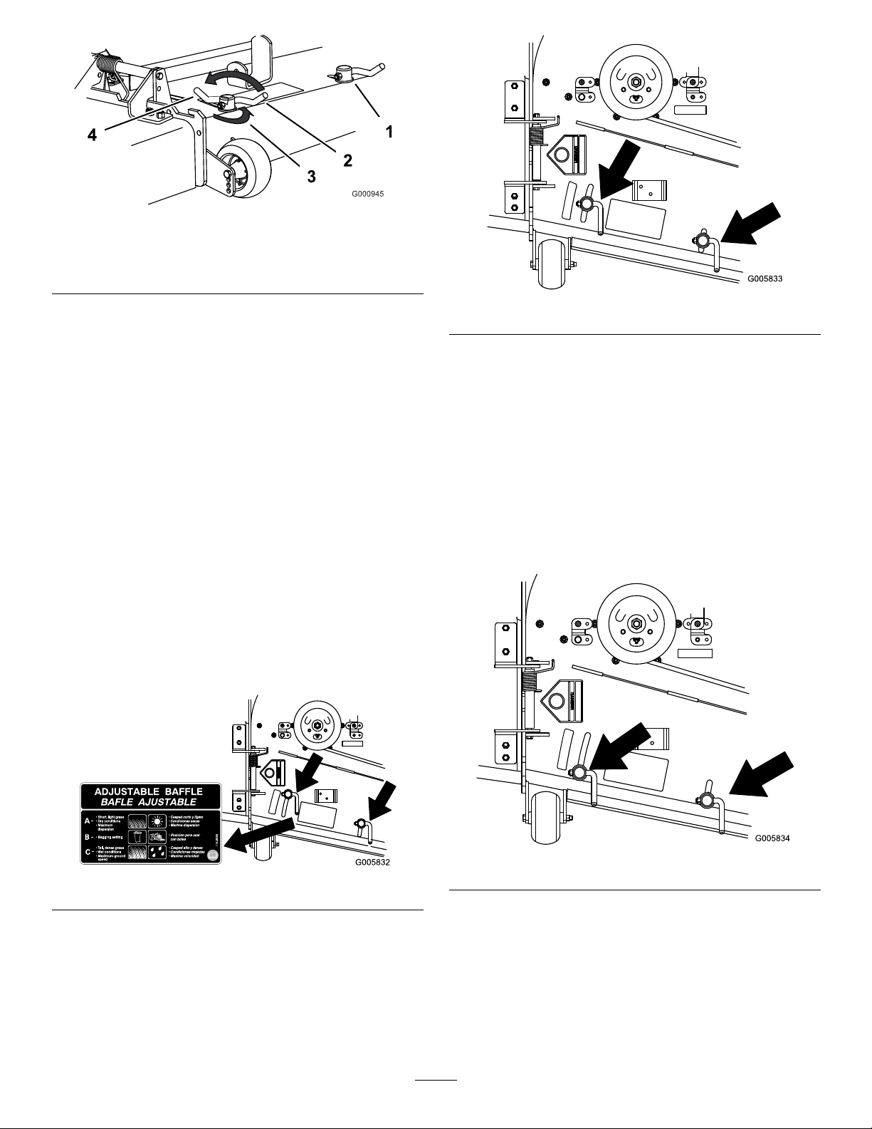
Figure23
1.Camlock
2.Lever
PositioningtheFlowBafe
3.Rotatecamtoincreaseor
decreaselockingpressure
4.Slot
Figure25
Thefollowingguresareonlyrecommendationsfor
use.Adjustmentswillvarybygrasstype,moisture
content,andheightofgrass.
Note:Iftheenginepowerdrawsdownandthemower
groundspeedisthesame,openupthebafe.
PositionA
Thisisthefullrearposition.Thesuggesteduseforthis
positionisafollows.
•Useforshort,lightgrassmowingconditions.
•Useindryconditions.
•Forsmallergrassclippings.
•Propelsgrassclippingsfartherawayfromthe
mower.
PositionC
Thisisthefullopenposition.Thesuggestedusefor
thispositionisasfollows.
•Useintall,densegrassmowingconditions.
•Useinwetconditions.
•Lowerstheenginepowerconsumption.
•Allowsincreasedgroundspeedinheavyconditions.
•ThispositionissimilartothebenetsoftheToro
SFSmower.
Figure24
PositionB
Usethispositionwhenbagging.
Figure26
PositioningtheSeat
ChangingtheSeatPosition
Theseatcanmoveforwardandbackward.Positionthe
seatwhereyouhavethebestcontrolofthemachine
andaremostcomfortable.
25
Page 26
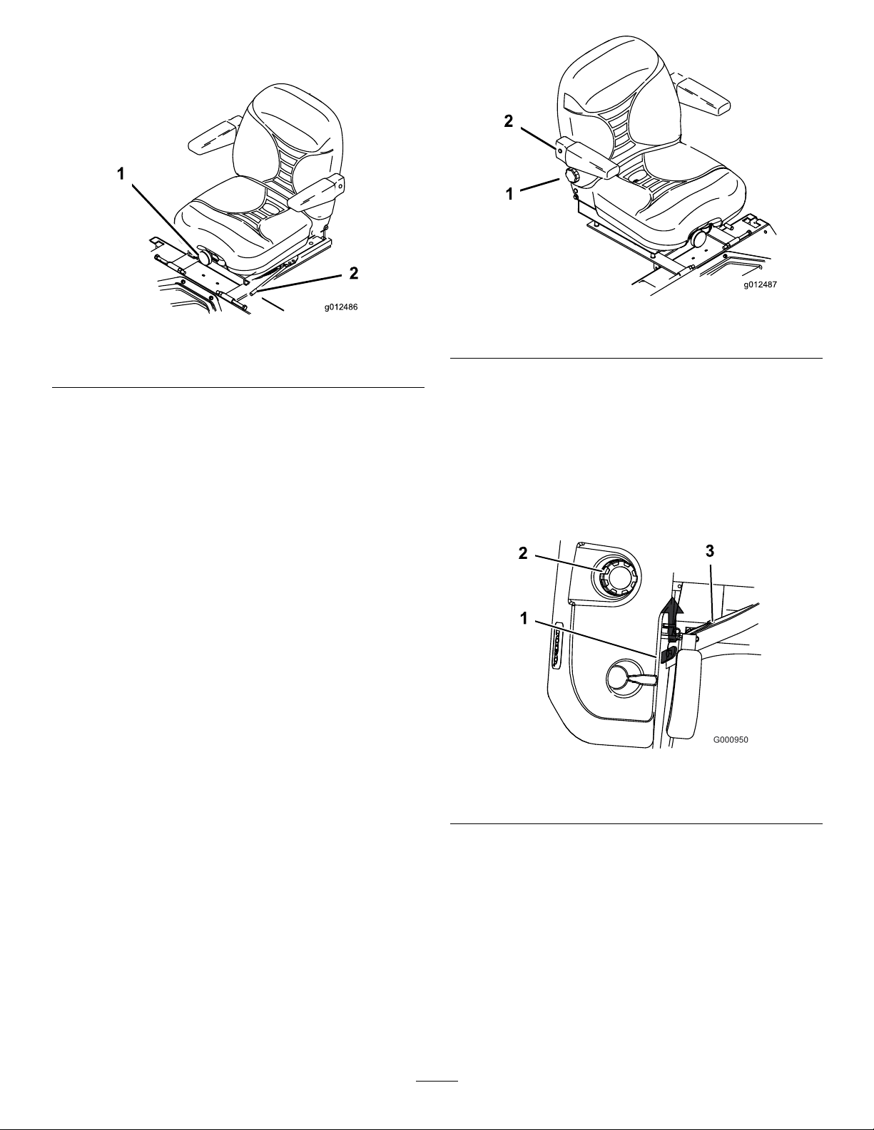
1.Toadjust,movetheleversidewaystounlockseat
g012486
g012487
(Figure27).
Figure27
1.Seatsuspensionknob2.Seatpositionadjustment
lever
Figure28
1.Backrestknob2.Right-sidearmrest
2.Slidetheseattothedesiredpositionandrelease
levertolockinposition.
ChangingtheSeatSuspension
Theseatcanbeadjustedtoprovideasmoothand
comfortableride.Positiontheseatwhereyouaremost
comfortable.
Toadjustit,turntheknobinfronteitherdirectionto
providethebestcomfort(Figure27).
ChangingtheBackPosition
Thebackoftheseatcanbeadjustedtoprovidea
comfortableride.Positionthebackoftheseatwhereit
ismostcomfortable.
Toadjustit,turntheknob,undertheright-sidearm
rest,ineitherdirectiontoprovidethebestcomfort
Figure28).
(
UnlatchingtheSeat
1.Movetheseattothemostrearwardposition.This
willpreventinterferencewhentheseatisraised.
2.Pushtheseatlatchrearwardtounlatchtheseat.
3.Raisetheseatup.Thiswillallowaccesstothe
machineundertheseat(Figure29).
Figure29
1.Seatlatch3.Seat
2.Fuelcap
PushingtheMachinebyHand
Important:Alwayspushthemachinebyhand.
Nevertowthemachinebecausehydraulicdamage
mayoccur.
PushingtheMachine
1.Disengagethepowertakeoff(PTO)andturnthe
ignitionkeytooff.Movetheleverstoneutrallocked
positionandapplyparkingbrake.Removethekey.
26
Page 27
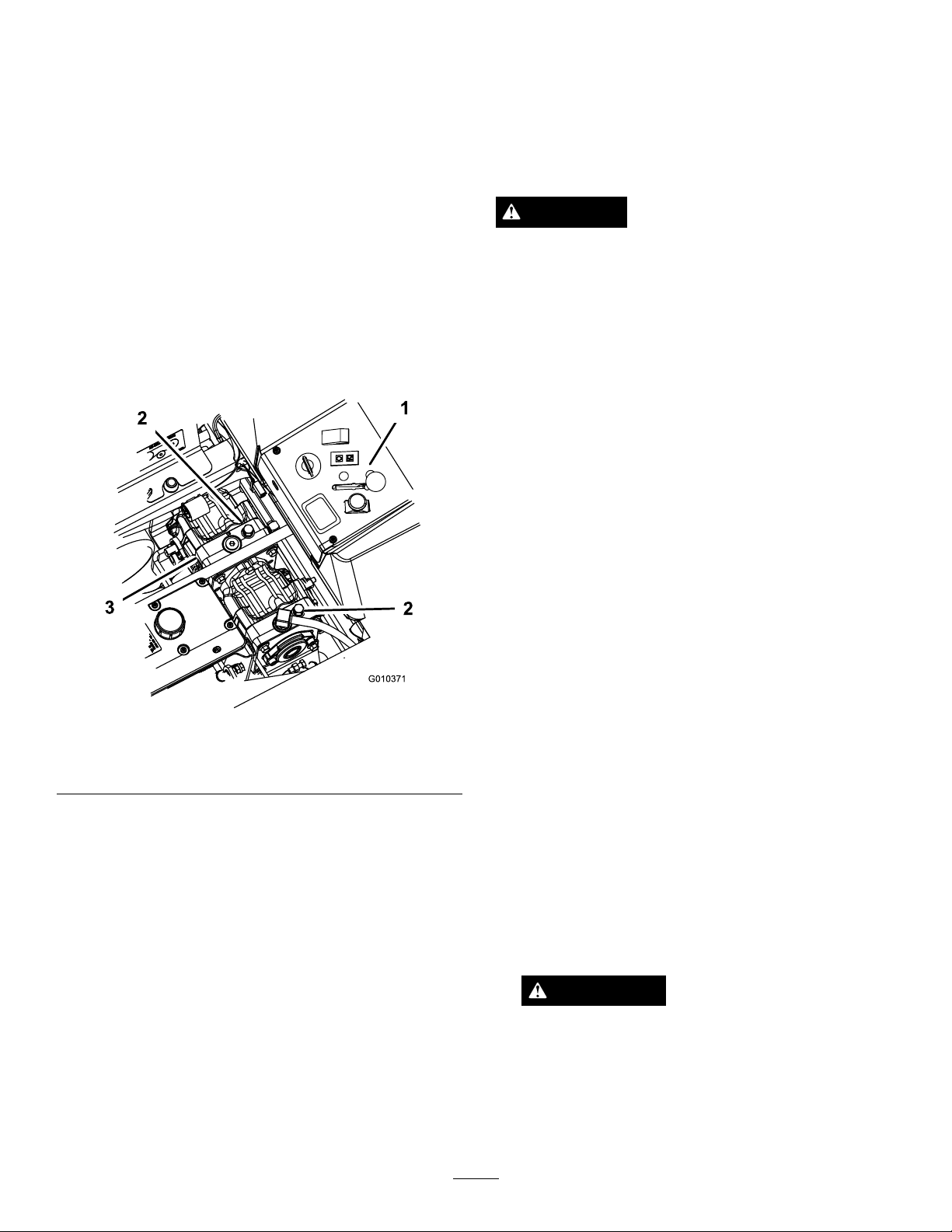
2.Rotatetheby-passvalvescounterclockwise1turn
topush.Thisallowshydraulicuidtoby-passthe
pumpenablingthewheelstoturn(Figure30).
enginecontinuestooverheat,takeyourmachinetoan
AuthorizedServiceDealer.
Important:Donotrotateby-passvalvesmore
than1turn.Thispreventsvalvesfromcoming
outofthebodyandcausinguidtorunout.
3.Disengageparkingbrakebeforepushing.
ChangingtoMachineOperation
Rotatetheby-passvalvesclockwise1turntooperate
machine(
Note:Donotovertightentheby-passvalves.
Themachinewillnotdriveunlessby-passvalvesare
turnedin.
Figure30).
UsingtheSideDischarge
Themowerhasahingedgrassdeectorthatdisperses
clippingstothesideanddowntowardtheturf.
DANGER
Withoutthegrassdeector,dischargecover,or
completegrasscatcherassemblymountedin
place,youandothersareexposedtobladecontact
andthrowndebris.Contactwithrotatingmower
blade(s)andthrowndebriswillcauseinjuryor
death.
•Neverremovethegrassdeectorfromthe
mowerbecausethegrassdeectorroutes
materialdowntowardtheturf.Ifthe
grassdeectoriseverdamaged,replaceit
immediately.
•Neverputyourhandsorfeetunderthemower.
•Nevertrytoclearthedischargeareaormower
bladesunlessyoumovethepowertakeoff
(PTO)totheoffposition,rotatetheignition
keytooffandremovethekey .
Figure30
1.Sideconsolecontrols
2.By-passvalve
3.Hydraulicpumps
OperatingwiththeOverheat
Sensor
Thismachinehasasensorthatwillturnoffthemower
deckwhentheengineoverheats.Whentheengine
overheats,theaudiblealarmandlightalarmwillturnon
alongwiththemowerdeckturningoff.
Ifthemowerdeckturnsoffautomaticallybecause
ofoverheating,theoperatorwillbeabletodrivethe
machinetoasafeareaandtoatruckortrailer.
Ifthemachineoverheats,ensuretheareaaround
theengineandradiatorisclearofanydebris.The
enginewillneedtobeturnedoffandallowedtocool
downbeforethemowerdeckcanbeengaged.Ifthe
•Makesurethegrassdeectorisinthedown
position.
TransportingMachines
Useaheavy-dutytrailerortrucktotransportthe
machine.Ensurethatthetrailerortruckhasall
necessarylightingandmarkingasrequiredbylaw .
Pleasecarefullyreadallthesafetyinstructions.
Knowingthisinformationcouldhelpyou,yourfamily,
petsorbystandersavoidinjury.
Totransportthemachine:
•Lockthebrakeandblockthewheels.
•Securelyfastenthemachinetothetrailerortruck
withstraps,chains,cable,orropes.
•Secureatrailertothetowingvehiclewithsafety
chains.
WARNING
Drivingonthestreetorroadwaywithoutturn
signals,lights,reectivemarkings,oraslow
movingvehicleemblemisdangerousandcan
leadtoaccidentscausingpersonalinjury.
Donotdrivemachineonapublicstreetor
roadway.
27
Page 28
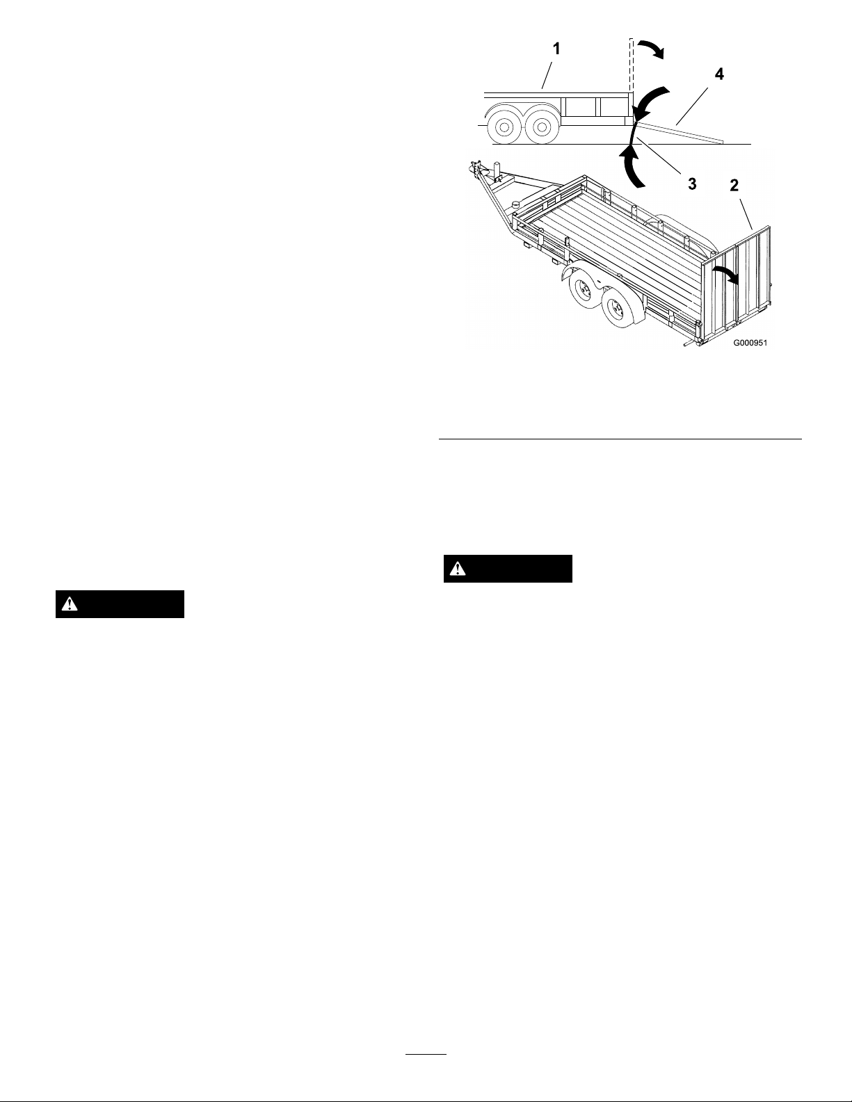
LoadingMachines
Useextremecautionwhenloadingunitsontrailersor
trucks.Onefullwidthrampthatiswideenoughto
extendbeyondthereartiresisrecommendedinsteadof
individualrampsforeachsideoftheunit(Figure31).
Thelowerrearsectionofthetractorframeextends
backbetweentherearwheelsandservesasastopfor
tippingbackward.Havingafullwidthrampprovides
asurfacefortheframememberstocontactifthe
unitstartstotipbackward.Ifitisnotpossibletouse
onefullwidthramp,useenoughindividualrampsto
simulateafullwidthcontinuousramp.
Therampshouldbelongenoughsothattheangles
donotexceed15degrees(
maycausemowercomponentstogetcaughtastheunit
movesfromramptotrailerortruck.Steeperangles
mayalsocausetheunittotipbackward.Ifloadingon
ornearaslope,positionthetrailerortrucksoitison
thedownsideoftheslopeandtherampextendsupthe
slope.Thiswillminimizetherampangle.Thetraileror
truckshouldbeaslevelaspossible.
Figure31).Asteeperangle
Figure31
1.Trailer3.Notgreaterthan
15degrees
2.Fullwidthramp4.Fullwidthramp—sideview
Important:DoNotattempttoturntheunitwhile
ontheramp;youmaylosecontrolanddriveoff
theside.
Avoidsuddenaccelerationwhendrivinguparampand
suddendecelerationwhenbackingdownaramp.Both
maneuverscancausetheunittotipbackward.
WARNING
Loadingaunitontoatrailerortruckincreasesthe
possibilityofbackwardtip-overandcouldcause
seriousinjuryordeath.
•Useextremecautionwhenoperatingauniton
aramp.
•Useonlyasingle,fullwidthramp;DoNotuse
individualrampsforeachsideoftheunit.
•Ifindividualrampsmustbeused,useenough
rampstocreateanunbrokenrampsurface
widerthantheunit.
•Donotexceeda15degreeanglebetweenramp
andgroundorbetweenrampandtraileror
truck.
UsingtheZStand®
TheZStand®raisesthefrontendofthemachineto
allowyoutocleanthemowerandremovetheblades.
WARNING
Themachinecouldfallontosomeoneandcause
seriousinjuryordeath.
•Useextremecautionwhenoperatingthe
machineontheZStand®.
•Useonlyforcleaningthemowerandremoving
theblades.
•DonotkeepthemachineontheZStandfor
extendedperiodsoftime.
•Alwaysturntheengineoff,settheparking
brake,andremovethekeybeforeperforming
anymaintenancetothemower.
DrivingupontotheZStand
Important:UsetheZStandonalevelsurface.
•Avoidsuddenaccelerationwhiledrivingunitup
aramptoavoidtippingbackward.
•Avoidsuddendecelerationwhilebackingunit
downaramptoavoidtippingbackward.
1.Raisethemowertothetransportposition.
2.Removethebracketpin(
28
Figure32).
Page 29
WARNING
Parkingbrakemaynotholdmachineparked
onZStandandcouldcausepersonalinjuryor
propertydamage.
DonotparkonZStandunlesswheelsare
chockedorblocked.
10.Performthemaintenance.
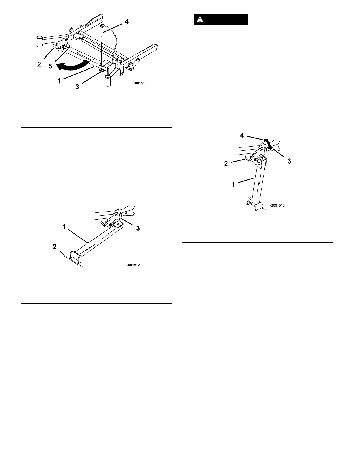
Figure32
1.ZStand
2.Latch
3.Bracket
4.BracketPin
5.Bottomofslot
3.Raisethelatch.Swingthestandfootoutfrontand
slidestandtowardmachine,intothebottomofslot
(Figure32andFigure33).
4.LengthentheZStandbyremovingtheclevispin
andhairpincotterpinfromtheoutertubeand
slidingthefootout.
5.Aligntheholesandinstalltheclevispinandhairpin
cotterpin.
DrivingofftheZStand
1.Removethechocksorblocks.
2.Raisethelatchtotheunlockedposition(Figure34).
Figure34
1.ZStand
2.Latch4.Unlockedposition
3.Starttheengineandplaceitathalfthrottle.
Disengagetheparkingbrake.
3.Lockedposition
Figure33
1.ZStand(Positionedin
slot)
2.Crackinsidewalkorturf
3.Latchrestingonpivottab
6.Setthefootofstandonthegroundandrestthe
latchonthepivottab(Figure33).
7.Starttheengineandputitathalfthrottle.
Note:Forbestresults,placethefootofstandinto
seamsinsidewalksorintotheturf(Figure33).
8.Driveontothestand.Stopwhenthelatchdrops
overthetabintothelockedposition(
Figure33).
Onceontothestand,engagetheparkingbrakeand
tunofftheengine.
9.Chockorblockthedrivewheels.
4.Slowlydrivebackwardsoffofthestand.
5.ShortentheZStandbyremovingtheclevispinand
hairpincotterpinfromtheoutertubeandsliding
thefootin.
6.Aligntheholesandinstalltheclevispinandhairpin
cotterpin.
7.Returnthestandtoitsrestposition(
Figure32).
OperatingTips
FastThrottleSetting
Forbestmowingandmaximumaircirculation,operate
theengineatthefastthrottleposition.Airisrequired
tothoroughlycutgrassclippings,sodonotsetthe
height-of-cutsolowastototallysurroundthemower
byuncutgrass.Alwaystrytohaveonesideofthe
mowerfreefromuncutgrass,whichallowsairtobe
drawnintothemower.
29
Page 30

CuttingaLawnfortheFirstTime
Cutgrassslightlylongerthannormaltoensurethe
cuttingheightofthemowerdoesnotscalpanyuneven
ground.However,thecuttingheightusedinthepastis
generallythebestonetouse.Whencuttinggrasslonger
thansixinchestall,youmaywanttocutthelawntwice
toensureanacceptablequalityofcut.
Cut1/3oftheGrassBlade
Itisbesttocutonlyabout1/3ofthegrassblade.
Cuttingmorethanthatisnotrecommendedunless
grassissparse,oritislatefallwhengrassgrowsmore
slowly.
MowingDirection
Alternatemowingdirectiontokeepthegrassstanding
straight.Thisalsohelpsdisperseclippingswhich
enhancesdecompositionandfertilization.
MowatCorrectIntervals
lawn.Toavoidthis,moveontoapreviouslycutarea
withthebladesengaged.
KeeptheUndersideoftheMower
Clean
Cleanclippingsanddirtfromtheundersideofthe
moweraftereachuse.Ifgrassanddirtbuildupinside
themower,cuttingqualitywilleventuallybecome
unsatisfactory.
BladeMaintenance
Maintainasharpbladethroughoutthecuttingseason
becauseasharpbladecutscleanlywithouttearingor
shreddingthegrassblades.Tearingandshreddingturns
grassbrownattheedges,whichslowsgrowthand
increasesthechanceofdisease.Checkthecutterblades
dailyforsharpness,andforanywearordamage.File
downanynicksandsharpenthebladesasnecessary.If
abladeisdamagedorworn,replaceitimmediatelywith
agenuineTOROreplacementblade.
Normally,moweveryfourdays.Butremember,
grassgrowsatdifferentratesatdifferenttimes.So
tomaintainthesamecuttingheight,whichisagood
practice,mowmoreofteninearlyspring.Asthegrass
growthrateslowsinmidsummer,mowlessfrequently .
Ifyoucannotmowforanextendedperiod,rstmow
atahighcuttingheight;thenmowagaintwodayslater
atalowerheightsetting.
CuttingSpeed
Toimprovecutquality,useaslowergroundspeedin
certainconditions.
AvoidCuttingTooLow
Ifthecuttingwidthofthemoweriswiderthanthe
moweryoupreviouslyused,raisethecuttingheightto
ensurethatuneventurfisnotcuttooshort.
LongGrass
Ifthegrassiseverallowedtogrowslightlylongerthan
normal,orifitcontainsahighdegreeofmoisture,raise
thecuttingheighthigherthanusualandcutthegrassat
thissetting.Thencutthegrassagainusingthelower,
normalsetting.
WhenStopping
Ifthemachine’sforwardmotionmustbestoppedwhile
mowing,aclumpofgrassclippingsmaydropontoyour
30
Page 31

Maintenance
RecommendedMaintenanceSchedule(s)
MaintenanceService
Interval
Aftertherst8hours
Aftertherst25hours
Aftertherst50hours
Aftertherst100hours
Beforeeachuseordaily
Every25hours
MaintenanceProcedure
•Checktheenginecoolingsystemlevel.
•Adjustthemowerbelttension(72inmowersonly).
•Checkthehydraulicuid.
•Changethehydrauliclter.
•Changetheengineoil.
•Changetheengineoillter.
•Checkthewheelhubslottednut.
•Checkthewheellugnuts.
•Changethegearboxoil.
•Checkthesafetysystem.
•Checktheengineoil.
•Checktheenginecoolingsystemlevel.
•Cleantheengineoilcooler.
•Checkthemowerblades.
•Cleanthemowerdeck.
•Greasethemowerdeckandspindles.
•Greasethemowerbeltidlerarm.
•Greasethepumpbeltidlerarm.
•GreasethePTOdrivebeltidlerarm.
•Greasethebrakelever.
•Checkthehydraulicuid.
Every40hours
Every50hours
Every100hours
Every150hours
Every200hours
Every250hours
Every400hours
•Drainthewaterseparator.
•Checkthetirepressure
•CheckthePTOdrivebelt.
•Checkthepumpdrivebelt.
•Checkthealternatorbelt.
•Changetheengineoil.
•Checkthegearboxoillevel.
•Checktheenginecoolingsystemhoses.
•Inspectthebeltsforcracksandwear.
•Checkthehydraulichoses.
•Lubricatethemachinewithlightoil(RefertoLubrication).
•Changetheengineoillter.
•Greasethebrakepivot.
•Checkand/orreplacetheairlter(moreoftenindirtyordustyconditions).
•ChangethehydrauliclterandhydraulicoilwhenusingMobil®1oil.
•Replacethefuellter(moreoftenindirtyordustyconditions).
31
Page 32

MaintenanceService
Interval
Every500hours
Yearly
MaintenanceProcedure
•Checkthewheelhubslottednut.
•Checkthewheellugnuts.
•Adjustthecasterpivotbearing
•Adjusttheelectricclutch.
•ChangethehydrauliclterandhydraulicoilwhenusingT oro®HYPR-OIL™500
hydraulicoil.
•Greasethefrontcasterpivots(moreoftenindirtyordustyconditions).
•Lubricatethecasterwheelhubs
•Changethegearboxoil.
•Changetheenginecoolant.
Important:Refertoyourengineoperator’smanualforadditionalmaintenanceprocedures.
CAUTION
Ifyouleavethekeyintheignitionswitch,someonecouldaccidentlystarttheengineandseriouslyinjure
youorotherbystanders.
Removethekeyfromtheignitionbeforeyoudoanymaintenance.
Lubrication
GreasingandLubrication
LubricatethemachinewhenshownontheCheck
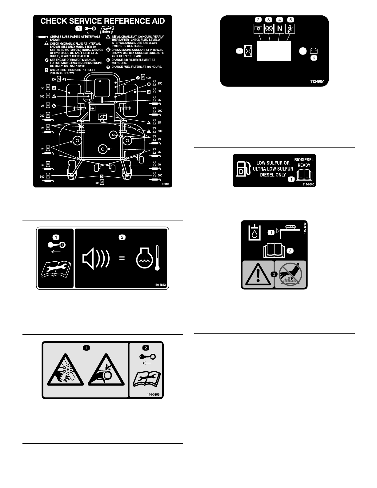
ServiceReferenceAiddecal(Figure35).Greasemore
frequentlywhenoperatingconditionsareextremely
dustyorsandy.
GreaseType:General-purposegrease.
HowtoGrease
1.DisengagethePTO,movethemotioncontrollevers
totheneutrallockedpositionandsettheparking
brake.
2.Stoptheengine,removethekey,andwaitforall
movingpartstostopbeforeleavingtheoperating
position.
3.Cleanthegreasettingswitharag.Makesureto
scrapeanypaintoffthefrontofthetting(s).
4.Connectagreaseguntothetting.Pumpgrease
intothettingsuntilgreasebeginstooozeoutof
thebearings.
5.Wipeupanyexcessgrease.
2.Removethehexplug.Threadagreasezerkintothe
hole.
3.Pumpgreaseintothezerkuntilitoozesoutaround
thetopbearing.
4.Removethegreasezerkinthehole.Installthehex
plugandcap.
WheretoAddGrease
LubricatethegreasettingsasshownontheCheck
ServiceReferenceAiddecal(Figure35).
GreasingtheFrontCasterPivots
ServiceInterval:Yearly(moreoftenindirtyordusty
conditions).
1.Removethedustcapandadjustthecasterpivots.
Keepthedustcapoffuntilgreasingisdone.
RefertoAdjustingtheCasterPivotBearingin
DriveSystemMaintenance(page43).
32
Page 33
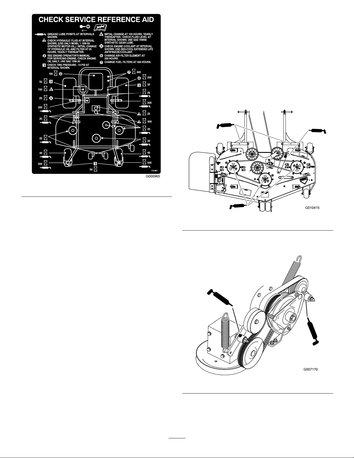
Figure35
Important:Makesurecuttingunitspindlesare
fullofgreaseweekly.
1.DisengagethePTO,movethemotioncontrollevers
totheneutrallockedpositionandsettheparking
brake.
2.Stoptheengine,removethekey,andwaitforall
movingpartstostopbeforeleavingtheoperating
position.
3.Greasetheidlerpulleypivot(
4.Greasethettingsonthe3spindlebearings
(Figure36).
Figure36).
WheretoAddLightOilorSpray
Lubrication
ServiceInterval:Every150hours
Lubricatethemachineinthefollowingareaswithspray
typelubricantorlightoil.
•Seatswitchactuator.
•Brakehandlepivot.
•Brakerodbushings.
•Motioncontrolbronzebushings.
GreasingtheMowerDeckand
BeltIdlers
ServiceInterval:Every25hours—Greasethemower
deckandspindles.
Every25hours—Greasethemower
beltidlerarm.
Every25hours—Greasethepump
beltidlerarm.
Figure36
5.GreasethePTOdrivebeltidlerarm(Figure37).
6.Greasethepumpbeltidlerarm(Figure37).
Figure37
Every25hours—GreasethePTO
drivebeltidlerarm.
GreasewithNo.2generalpurposelithiumbaseor
molybdenumbasegrease.
LubricateCasterWheelHubs
ServiceInterval:Yearly
33
Page 34

1.Stoptheengine,waitforallmovingpartstostop,
andremovethekey.Engagetheparkingbrake.
Figure38
1.Sealguard2.Spacernutwithwrench
ats
2.Removethecasterwheelfromthecasterforks.
3.Removethesealguardsfromthewheelhub.
4.Removeoneofthespacernutsfromtheaxle
assemblyinthecasterwheel.Notethatthread
lockingadhesivehasbeenappliedtolockthespacer
nutstotheaxle.Removetheaxle(withtheother
spacernutstillassembledtoit)fromthewheel
assembly.
13.Torquethenutto75-80in-lb(8-9N-m),loosen,
thenre-torqueto20-25in-lb(2-3N-m).Makesure
axledoesnotextendbeyondeithernut.
14.Reinstallthesealguardsoverthewheelhuband
insertwheelintocasterfork.Reinstallcasterbolt
andtightennutfully .
Important:Topreventsealandbearingdamage,
checkthebearingadjustmentoften.Spinthecaster
tire.Thetireshouldnotspinfreely(morethan1or
2revolutions)orhaveanysideplay .Ifthewheel
spinsfreely,adjusttorqueonspacernutuntilthere
isaslightamountofdrag.Reapplythreadlocking
adhesive.
5.Pryoutseals,andinspectbearingsforwearor
damageandreplaceifnecessary.
6.Packthebearingswithageneral-purposegrease.
7.Insertonebearing,onenewsealintothewheel.
Note:Thesealsmustbereplaced.
8.Iftheaxleassemblyhashadbothspacernuts
removed(orbrokenloose),applyathreadlocking
adhesivetoonespacernutandthreadontotheaxle
withthewrenchatsfacingoutward.DoNotthread
spacernutallofthewayontotheendoftheaxle.
Leaveapproximately1/8inch(3mm)fromthe
outersurfaceofthespacernuttotheendoftheaxle
insidethenut.
9.Inserttheassemblednutandaxleintothewheelon
thesideofthewheelwiththenewsealandbearing.
10.Withtheopenendofthewheelfacingup,ll
theareainsidethewheelaroundtheaxlefullof
general-purposegrease.
11.Insertthesecondbearingandnewsealintothe
wheel.
12.Applyathreadlockingadhesivetothe2ndspacer
nutandthreadontotheaxlewiththewrenchats
facingoutward.
34
Page 35
EngineMaintenance
ServicingtheAirCleaner
Note:Checktheltersmorefrequentlyifoperating
conditionsareextremelydustyorsandy.
RemovingtheAirFilter
ServiceInterval:Every250hours(moreoftenindirty
ordustyconditions).
1.DisengagethePTO,movethemotioncontrollevers
totheneutrallockedpositionandsettheparking
brake.
2.Stoptheengine,removethekey,andwaitforall
movingpartstostopbeforeleavingtheoperating
position.
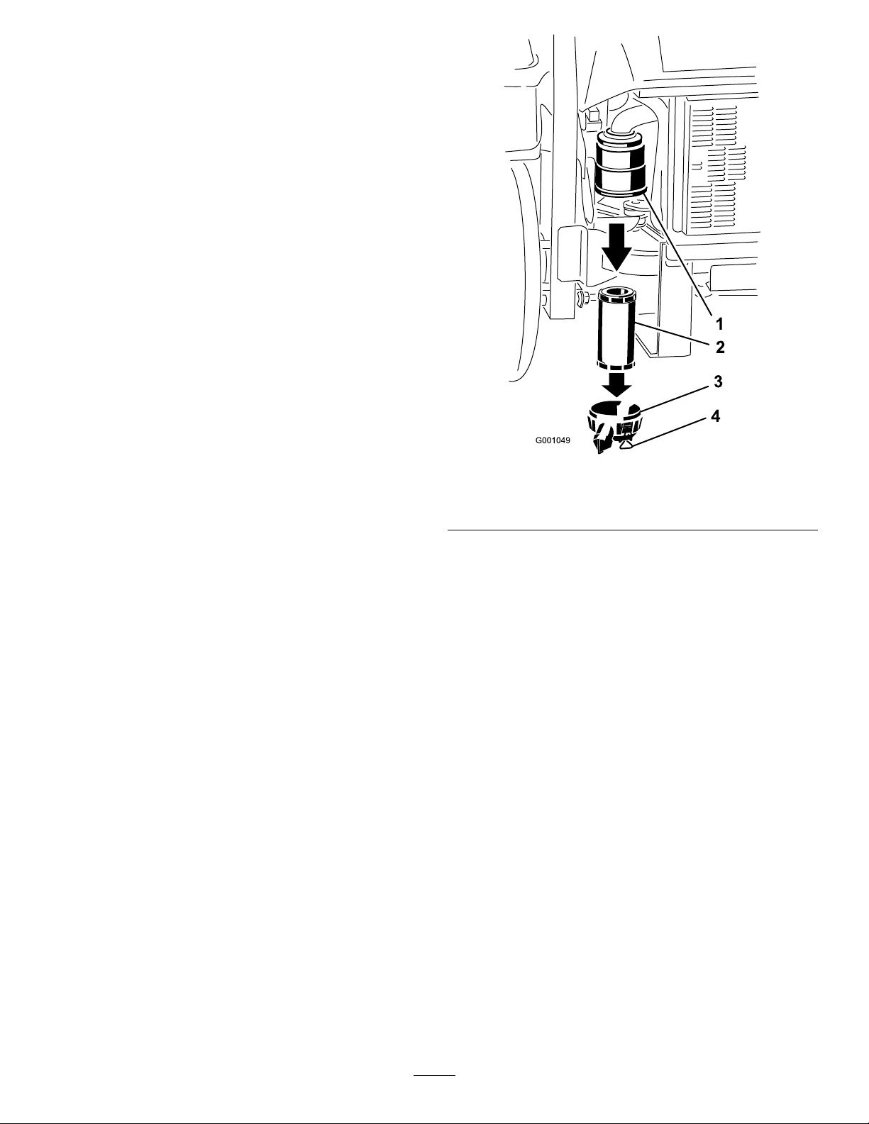
3.Releasethelatchesontheaircleanerandpulltheair
cleanercoveroffoftheaircleanerbody(
4.Cleantheinsideoftheaircleanercoverwith
compressedair.
5.Gentlyslidethelteroutoftheaircleanerbody
Figure39).Avoidknockingthelterintotheside
(
ofthebody.
Figure39).
1.Airlterbody
2.Airlter
Figure39
3.Aircleanercover
4.Latches
6.Inspectthelterfordamagebylookingintothe
lterwhileshiningabrightlightontheoutsideof
thelter.Holesinthelterwillappearasbright
spots.Ifthelterisdamageddiscardit.
InstallingtheAirFilter
1.Ifinstallinganewlter,checkthelterforshipping
damage.Donotuseadamagedlter.
2.Carefullyslidethelterintothelterbody
Figure40).Ensurethatitisfullyseatedbypushing
(
ontheouterrimofthelterwhileinstallingit.
Important:Donotpressonthesoftinsidearea
ofthelter.
3.Installtheaircleanercoverandsecurethelatches
(Figure40).
35
Page 36
CheckingtheEngineOilLevel
ServiceInterval:Beforeeachuseordaily
Note:Checktheoilwhentheengineiscold.
1.DisengagethePTO,movethemotioncontrollevers
totheneutrallockedpositionandsettheparking
brake.
2.Stoptheengine,removethekey,andwaitforall
movingpartstostopbeforeleavingtheoperating
position.
Figure40
1.Airlterbody
2.Airlter
3.Aircleanercover
4.Latches
ServicingtheEngineOil
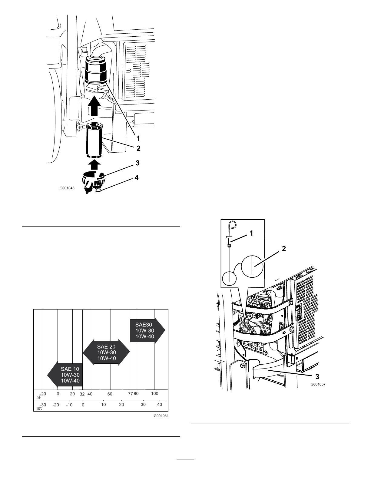
OilType:High-qualitydetergentoilclassiedAPI
ServiceCDorhigherfordieselengines.Donotuse
specialadditiveswithrecommendedoils.
3.Cleanaroundtheoildipstick(
Figure42)sodirt
cannotfallintothellerholeanddamagetheengine.
4.Pulltheoildipstickoutandwipethemetalendclean
(Figure42).
5.Slidetheoildipstickfullyintothellertube.Pullthe
dipstickoutandlookatthemetalend(Figure42).If
theoillevelislow,slowlypouronlyenoughoilinto
thellholetoraisetheleveltothefullmark.
Important:Donotoverllthecrankcasewith
oilbecausethismaycauseenginedamage.Do
notruntheenginewithoilbelowthelowmark
becausetheenginemaybedamagedasaresult.
CrankcaseCapacity:3.9quarts(3.7liters)
Viscosity:Seethetablebelow .
Figure41
Figure42
1.Oildipstick3.Rearleftsideofmachine
2.Metalend
36
Page 37
ChangingtheEngineOil
ServiceInterval:Aftertherst50hours
Every100hours
1.Starttheengineandletitrunforveminutes.This
warmstheoilsoitdrainsbetter.
2.Parkthemachineonalevelsurface.
3.DisengagethePTO,movethemotioncontrollevers
totheneutrallockedpositionandsettheparking
brake.
4.Stoptheengine,removethekey,andwaitforall
movingpartstostopbeforeleavingtheoperating
position.
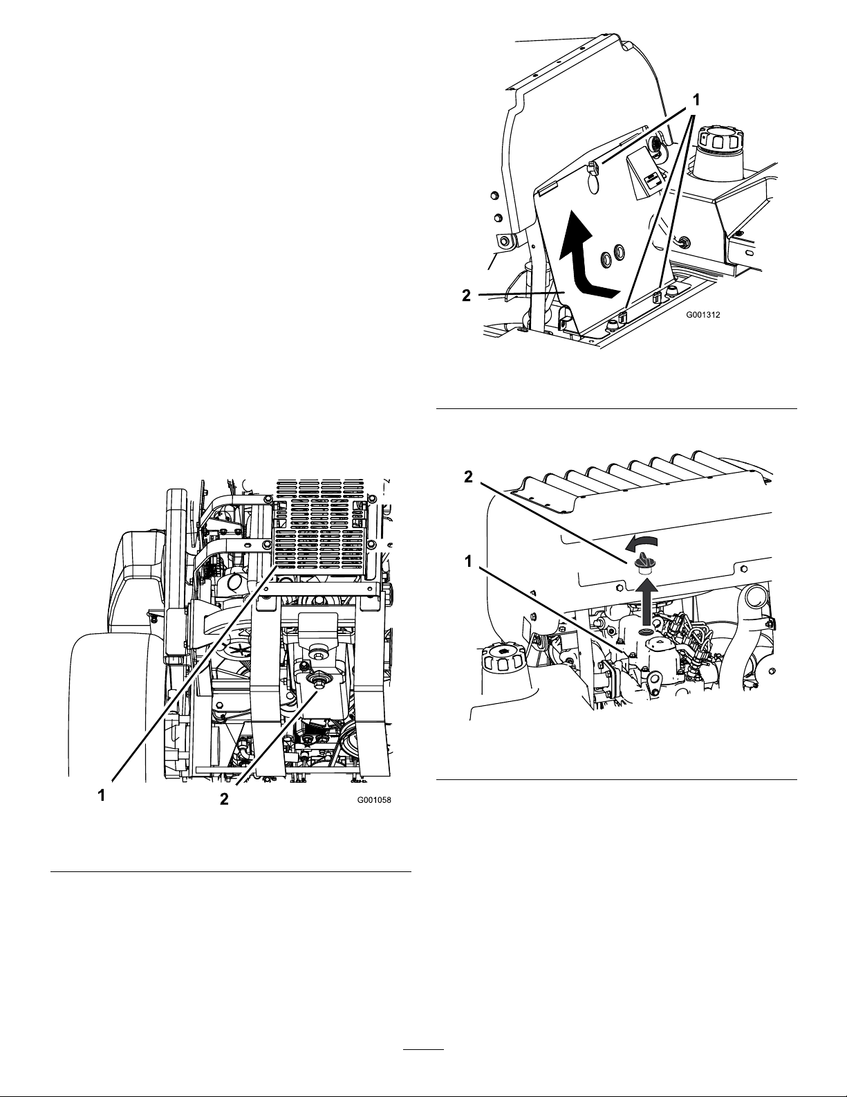
5.Placeapanbelowtheoildrain.Removethedrain
plugandlettheoildraincompletely(
6.Removetheoilllercapfromthetopoftheengine
(Figure45).Thiswillhelptheoiltodrain.
7.Installthedrainplugandtightenitto25-1/2ft-lb
(35N-m).
Figure43).
Figure44
1.Knob2.Frontenginepanel
2.Removetheoilllercapandthedipstick(Figure45).
Note:Disposeoftheusedoilatarecyclingcenter.
Figure43
1.Backofmachine
2.Drainplug
AddingEngineOil
1.Tilttheseatforwardandremovethefrontengine
panel(Figure44).
Figure45
1.Engine
2.Oilllcap
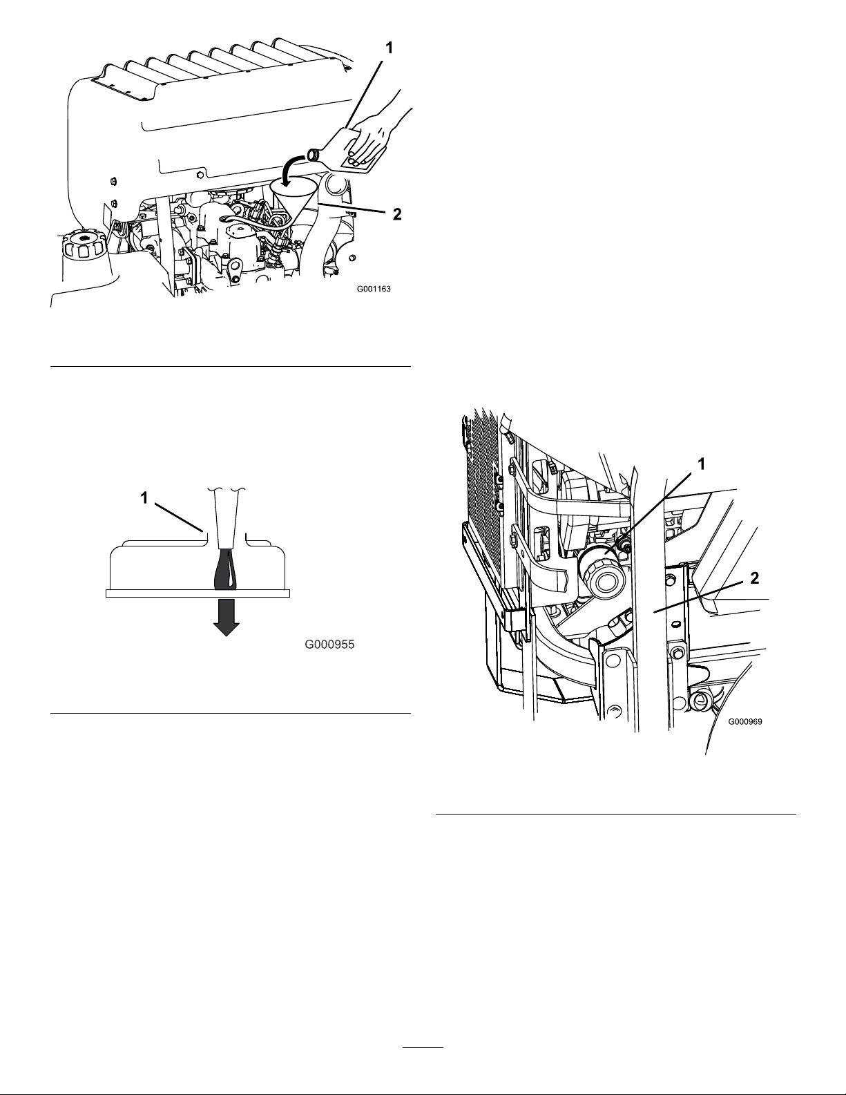
3.Toaddoiltotheengine,locateanduseahoseand
funnelforaddingoil(Figure46).
4.Addoilslowly,checkingthelevelwiththe
dipstickfrequentlyuntilthelevelreachesthe
upperholeonthedipstick.Forthecorrectoil
typeandviscositytouseindifferenttemperature
conditions,refertoServicingtheEngineOilin
EngineMaintenance(page35),).
37
Page 38
ChangingtheEngineOilFilter
ServiceInterval:Aftertherst50hours
Every200hours
1.Placeadrippanbeneaththeoildriptraytoreceive
oilfromtheoillterandoilpassagesintheengine.
2.Draintheoilfromtheengine;refertoChangingthe
EngineOil.
3.Turntheltercounterclockwisetoremoveit
Figure48andFigure49).
(
Note:Disposeoftheoillterproperly .Recyclein
accordancewithlocalcodes.
Figure46
1.Engineoil2.Funnelandhose
Important:Addtheoilveryslowlyanddonot
blocktheopeningofthellerhole(Figure47).
Ifyouaddoiltoofastorblockthehole,theoil
couldbackupandfoultheairintakes,causing
enginedamage.
Figure47
1.Notetheclearanceleftinthelleropening.
4.Beforeinstallingthelter,lightlyoilthegasketon
thelterwithfresh,cleanoil.Screwthelteronby
handuntilthegasketcontactstheoillteradapter.
Tighten1/2to3/4turnmore.
5.Addoil;refertoAddingEngineOil.
5.Replacethedipstickandinstallthefrontengine
panel.
6.Starttheengineandrunitatidlefor5minutes.
7.Shutofftheengine.
8.Wait3minutesandchecktheoillevel.
9.Addoil,ifrequired,tobringtheleveltotheupper
holeonthedipstick.
10.Replacethedipstickand,llercap,andthefront
enginepanel.
11.Checkforleaks.
Important:Donotoverllthecrankcasewith
oilbecausethismaycauseenginedamage.
Figure48
1.Oillter2.Rightsideofmachine
38
Page 39
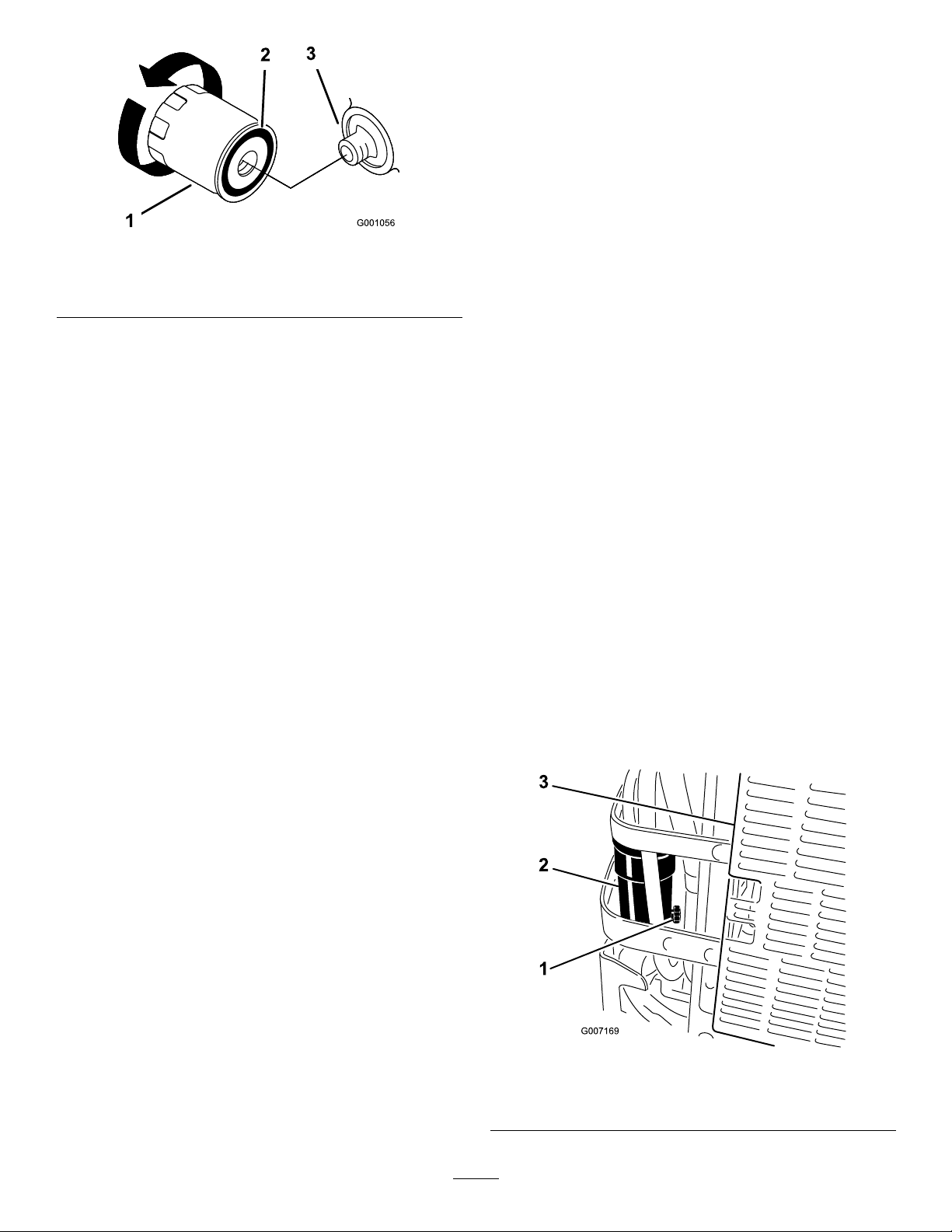
1.Oillter
2.Gasket
Figure49
FuelSystem
Maintenance
ServicingtheFuelFilterand
WaterSeperator
ServiceInterval:Every40hours—Drainthewater
separator.
3.Adapter
DrainingtheWaterSeparator
1.Positionthemachineonalevelsurface.
2.DisengagethePTO,movethemotioncontrollevers
totheneutrallockedpositionandsettheparking
brake.
3.Stoptheengine,removethekey,andwaitforall
movingpartstostopbeforeleavingtheoperating
position.
Every400hours/Yearly(whichever
comesrst)—Replacethefuel
lter(moreoftenindirtyordusty
conditions).
4.Locatethewaterseparatoratthebackleftofthe
machine.
5.Placeadrainpanbelowthewaterseparator.
6.Openthedrainvalveonthewaterseparator
approximatelyoneturntoallowwaterandother
contaminatestodrain(
7.Closethedrainvalvewhenonlydieselfuelcomes
Figure50).
out(
Figure50).
Figure50
1.Drainvalve
2.Waterseparator
39
3.Backofmachine
Page 40
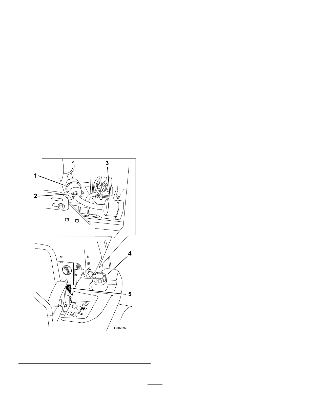
ChangingtheFuelFilter
ServicingtheFuelTank
Neverinstalladirtyfuellterifitisremovedfromthe
fuelline.
1.Allowthemachinetocooldown.
2.DisengagethePTO,movethemotioncontrollevers
totheneutrallockedpositionandsettheparking
brake.
3.Stoptheengine,removethekey,andwaitforall
movingpartstostopbeforeleavingtheoperating
position.
4.Closethefuelshut-offvalve(
Figure51).
5.Loosenthetwohoseclampsanddisconnectthefuel
linesfromthefuellter(Figure51).
6.Installanewlter.Connectthefuellinestothefuel
lterandinstallthetwohoseclamps(
Figure51).
7.Openthefuelshut-offvalve.
8.Starttheengineandcheckforleaks.
Donotattempttodrainthefueltank.Ensurethatan
AuthorizedServiceDealerdrainsthefueltankand
servicesanycomponentsofthefuelsystem.
Figure51
1.Fuellter4.Leftsideofmachine
2.Hoseclamp
3.Fuelpump
5.Fuelshut-offvalve
40
Page 41
ElectricalSystem
Maintenance
ServicingtheBattery
1.DisengagethePTO,movethemotioncontrollevers
totheneutrallockedpositionandsettheparking
brake.
2.Stoptheengine,removethekey,andwaitforall
movingpartstostopbeforeleavingtheoperating
position.
WARNING
CALIFORNIA
Proposition65Warning
Batteryposts,terminals,andrelated
accessoriescontainleadandleadcompounds,
chemicalsknowntotheStateofCalifornia
tocausecancerandreproductiveharm.
Washhandsafterhandling.
DANGER
Batteryelectrolytecontainssulfuricacidwhichisa
deadlypoisonandcausessevereburns.
Donotdrinkelectrolyteandavoidcontactwith
skin,eyesorclothing.Wearsafetyglassestoshield
youreyesandrubberglovestoprotectyourhands.
RemovingtheBattery
WARNING
Batteryterminalsormetaltoolscouldshortagainst
metalmachinecomponentscausingsparks.Sparks
cancausethebatterygassestoexplode,resulting
inpersonalinjury.
•Whenremovingorinstallingthebattery,donot
allowthebatteryterminalstotouchanymetal
partsofthemachine.
•Donotallowmetaltoolstoshortbetween
thebatteryterminalsandmetalpartsofthe
machine.
3.Unlatchtheseatandtilttheseatup.
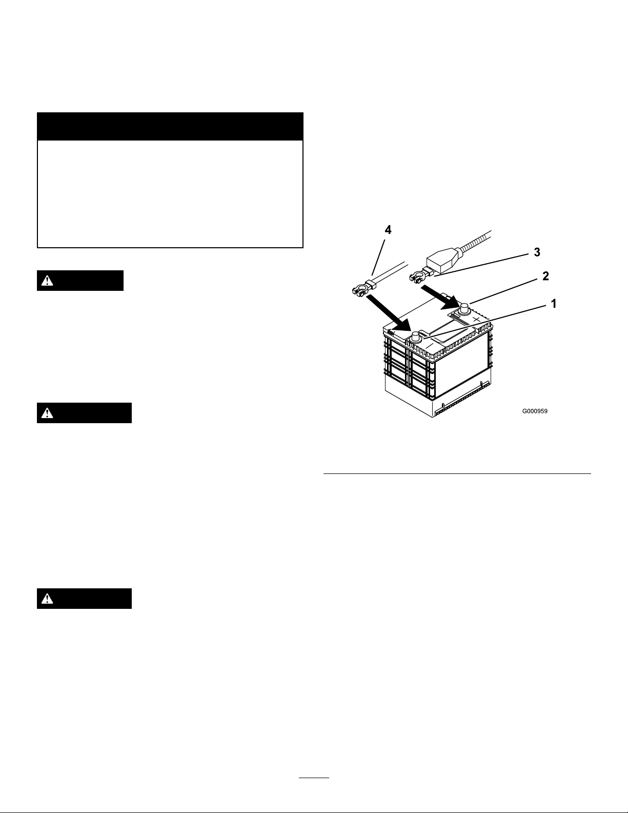
4.Firstdisconnectthenegativebatterycablefromthe
negative(-)batteryterminal(
5.Slidetheredterminalbootoffthepositive(red)
batteryterminal.Thenremovethepositive(red)
batterycable(Figure52).
Figure52
1.NegativeBatteryPost
2.PositiveBatteryPost
6.Removebothwingnuts(1/4inch)securingthe
batteryclamp(Figure53).
7.Removethetwoboltsholdingthehydraulictankin
place(
8.Slidethehydraulictankawayfromthebattery.
9.Removethebattery.
Figure53).
Figure52).
3.Red(+)cable
4.Black(-)cable
WARNING
Incorrectbatterycableroutingcoulddamagethe
machineandcablescausingsparks.Sparkscan
causethebatterygassestoexplode,resultingin
personalinjury.
•AlwaysDisconnectthenegative(black)battery
cablebeforedisconnectingthepositive(red)
cable.
•AlwaysReconnectthepositive(red)battery
cablebeforereconnectingthenegative(black)
cable.
41
Page 42
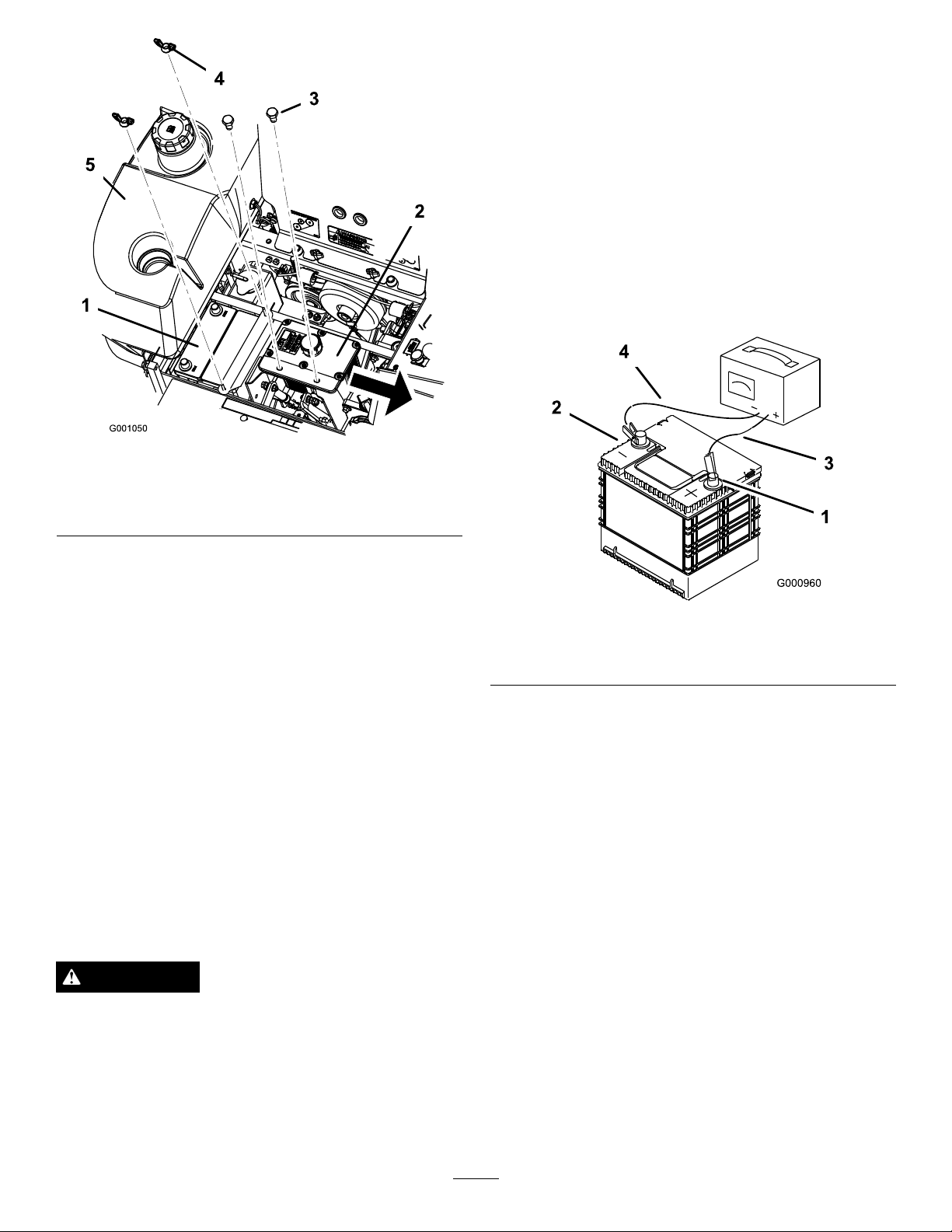
Figure53
1.Battery4.Wingnut
2.Hydraulictank
3.Bolts
5.Rightsidefueltank
topreventbatterydamagewhenthetemperatureis
below32°F(0°C).
1.Makesurethellercapsareinstalledinbattery.
Chargebatteryfor10to15minutesat25to30amps
or30minutesat10amps.
2.Whenthebatteryisfullycharged,unplugthecharger
fromtheelectricaloutlet,thendisconnectthe
chargerleadsfromthebatteryposts(
Figure54).
3.Installthebatteryinthemachineandconnectthe
batterycables,refertoInstallingtheBattery.
Note:Donotrunthemachinewiththebattery
disconnected,electricaldamagemayoccur.
InstallingtheBattery
1.Positionbatteryinthetraywiththeterminalposts
oppositefromthehydraulictank(Figure52).
2.First,installthepositive(red)batterycableto
positive(+)batteryterminal.
3.Theninstallthenegativebatterycableandground
wiretothenegative(-)batteryterminal.
4.Securethecableswith2bolts(1/4x3/4inch),
2washers(1/4inch),and2locknuts(1/4inch)
Figure52).
(
5.Slidetheredterminalbootontothepositive(red)
batterypost.
6.SecurebatterywithJ-bolts,holddownclampand
2washers(1/4inch),and2wingnuts(1/4inch)
Figure53).
(
ChargingtheBattery
WARNING
Chargingthebatteryproducesgassesthatcan
explode.
Figure54
1.PositiveBatteryPost
2.NegativeBatteryPost
3.Red(+)ChargerLead
4.Black(-)ChargerLead
ServicingtheFuses
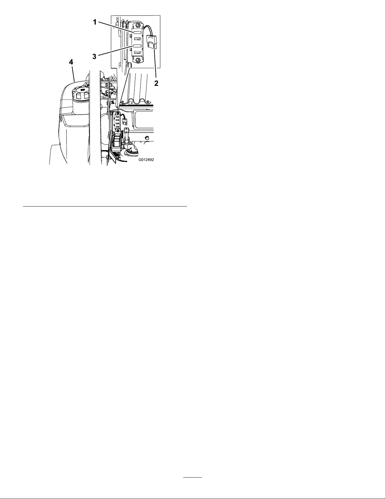
Theelectricalsystemisprotectedbyfuses.Itrequires
nomaintenance,however,ifafuseblowscheck
component/circuitformalfunctionorshort.
1.Unlatchtheenginehoodandraisetheenginehood
togainaccesstofuseholder(
2.Toreplacethefuses,pulloutonthefusetoremove
it.
3.Installanewfuse(
Figure55).
Figure55).
Neversmokenearthebatteryandkeepsparksand
amesawayfrombattery.
Important:Alwayskeepthebatteryfullycharged
(1.265specicgravity).Thisisespeciallyimportant
42
Page 43
1
3
2
G012492
4
Figure55
1.Ignition-30amp(F1)3.Clutch-10amp(F3)
2.Radiatorfan-50amp
(large,heavydutyfuse)
4.Leftsidefueltank
DriveSystem
Maintenance
AdjustingtheTracking
Themachinehasaknobforadjustingthetracking
locatedundertheseat.
Important:Adjustthehandleneutralandhydraulic
pumpneutralbeforeadjustingthetracking.Refer
toAdjustingtheHandleNeutralinMaintenance
andAdjustingtheHydraulicPumpNeutral
inMaintenance.
1.Pushbothcontrolleversforwardthesamedistance.
2.Checkifthemachinepullstooneside.Ifitdoes,
stopthemachineandsettheparkingbrake.
3.Unlatchtheseatandtilttheseatforwardtoaccess
thetrackingknob.
Note:Determinetheleftandrightsidesofthe
machinefromthenormaloperatingposition.
4.Tomakethemachinegoright,turntheknobtowards
therightsideofthemachine.Referto
5.Tomakethemachinegoleft,turntheknobtowards
theleftsideofthemachine.Referto
6.Repeatadjustmentuntilthetrackingiscorrect.
Figure56.
Figure56.
43
Page 44
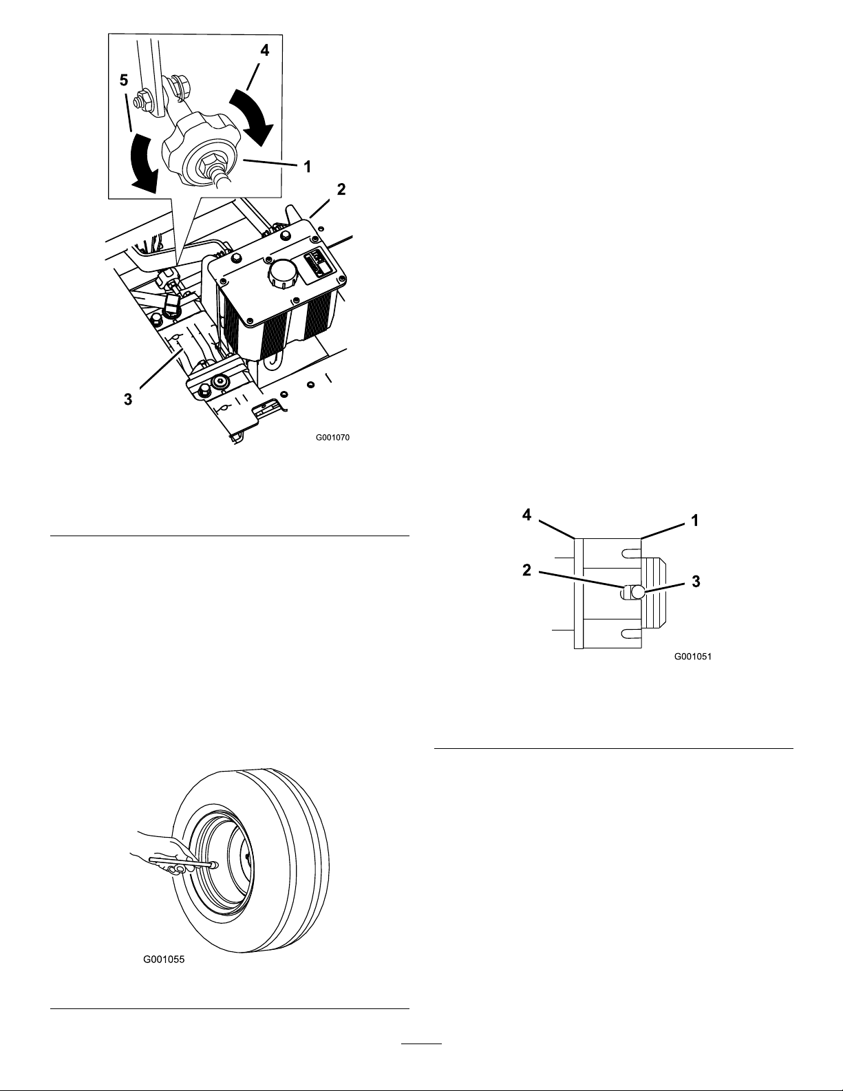
Figure56
1.Trackingknob4.Turnthiswaytotrackright
2.Hydraulictank
3.Hydraulicpumps
5.Turnthiswaytotrackleft
CheckingtheWheelHub
SlottedNut
ServiceInterval:Aftertherst100hours—Checkthe
wheelhubslottednut.
Every500hours—Checkthewheel
hubslottednut.
Aftertherst100hours—Checkthe
wheellugnuts.
Every500hours—Checkthewheel
lugnuts.
Theslottednutneedstobetorquedto125ft-lb
(170N-m).
1.DisengagethePTO,movethemotioncontrollevers
totheneutrallockedpositionandsettheparking
brake.
2.Stoptheengine,removethekey,andwaitforall
movingpartstostopbeforeleavingtheoperating
position.
3.Removethecotterpin.
4.Checkthedistancefrombottomofslotinnutto
insideedgeofhole.Twothreadsorlessshouldbe
showing(
Figure58).
CheckingtheTirePressure
ServiceInterval:Every50hours/Monthly(whichever
comesrst)
Maintaintheairpressureinthereartiresat13psi(90
kPa).Uneventirepressurecancauseunevencut.Check
thetireswhentheyarecoldtogetthemostaccurate
pressurereading.
Note:Thefronttiresaresemi-pneumatictiresanddo
notrequireairpressuremaintenance.
Figure57
Figure58
1.SlottedNut3.Holeinthreadedshaft
2.Twothreadsorless
showing
4.Washer(ifneeded)
5.Ifmorethantwothreadsareshowingremovenut
andinstallwasherbetweenhubandnut.
6.Torquetheslottednutto125ft-lb.(170N-m)
(
Figure58).
7.Tightenthenutuntilthenextsetofslotslineupwith
theholeintheshaft(Figure58).
8.Replacethecotterpin.
AdjustingtheCasterPivot
Bearing
ServiceInterval:Every500hours(oryearly,whichever
comesrst).
44
Page 45
1.DisengagethePTO,movethemotioncontrollevers
totheneutrallockedpositionandsettheparking
brake.
2.Stoptheengine,removethekey,andwaitforall
movingpartstostopbeforeleavingtheoperating
position.
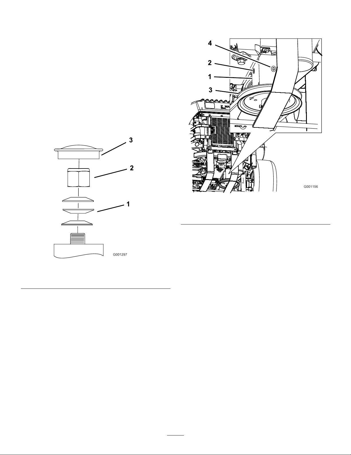
3.Removethedustcapfromcasterandtightenlock
Figure59).
nut(
4.Tightenthelocknutuntilthespringwashersareat
andthenbackoffa1/4turntoproperlysetthe
pre-loadonthebearings(
Figure59).
Important:Makesurespringwashersare
installedcorrectlyasshowninFigure59.
5.Installthedustcap(Figure59).
5.Theoilshouldbeuptotheopeningofthegearbox.
6.Addoilifneededtobringittothecorrectlevel.
Figure59
1.SpringWashers3.DustCap
2.LockNut
ServicingtheGearBox
CheckingtheGearBoxOilLevel
ServiceInterval:Every100hours
UseSAE75W–90SyntheticGearLube.
1.Parkthemachineonalevelsurface.
2.DisengagethePTO,movethemotioncontrollevers
totheneutrallockedpositionandsettheparking
brake.
3.Stoptheengine,removethekey,andwaitforall
movingpartstostopbeforeleavingtheoperating
position.
4.Removethesideorrearplugonthegearbox.
(
Figure60).
Figure60
1.Gearbox
2.Sideplug
3.Pulley
4.Rearplug
ChangingtheGearBoxOil
ServiceInterval:Aftertherst100hours
Yearly
ContactanAuthorizedServiceDealertochangethe
gearboxoil.
AdjustingtheElectricClutch
ServiceInterval:Every500hours
Theclutchisadjustabletoensureproperengagement
andproperbraking.
1.DisengagethePTO,movethemotioncontrollevers
totheneutrallockedpositionandsettheparking
brake.
2.Stoptheengine,removethekey,andwaitforall
movingpartstostopbeforeleavingtheoperating
position.
3.Unlatchtheseatandtipitforward.
4.Loosenthefrontenginepanelknobsandremove
thepanel.
45
Page 46
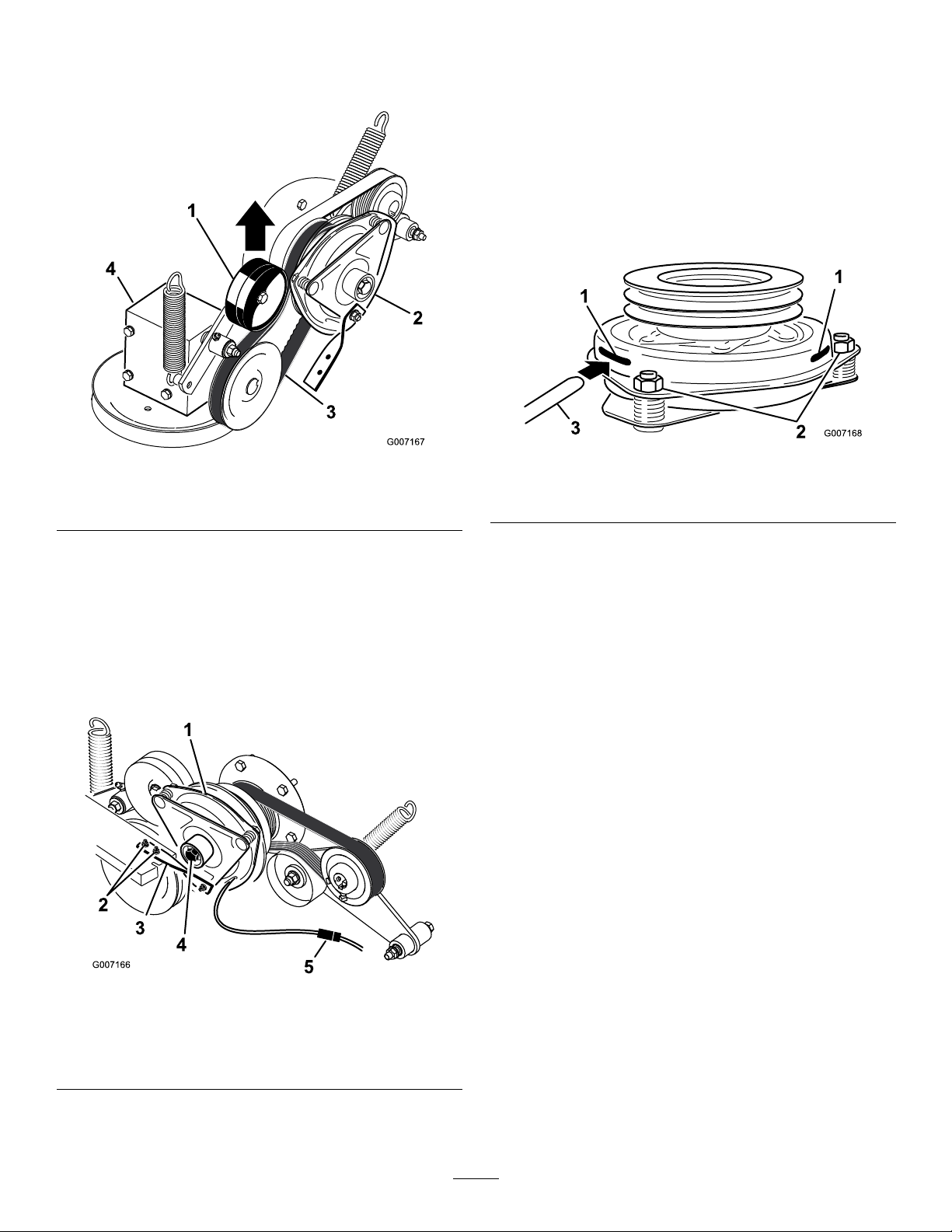
5.PulluponthespringloadedidlerpulleyforthePTO
drivebeltandremovethebeltfromtheclutchpulley
(Figure61).
assembly.Makesureitisbetweenthearmatureand
therotorfrictionsurfaces(Figure63).
10.Tightenthelocknutsuntilthereisslightbindingon
thefeelergaugebutitcanbemovedeasilywithinthe
airgap(
Figure63).
11.Repeatthisfortheremainingslots.
12.Checkeachslotagainandmakeslightadjustments
untilthefeelergaugebetweentherotorandarmature
hasveryslightcontactbetweenthem.
Figure61
1.Springloadedidlerpulley3.PTOdrivebelt
2.Clutch4.Gearbox
6.Unplugtheelectricconnectionfortheclutch
(Figure62).
7.Removethetwoboltsholdingtherubberclutch
straptothemowerframe(Figure62).
8.Removethecenterboltholdingtheclutchto
theengineshaftandremovetheclutchandkey
Figure62).
(
Figure63
1.Slot
2.Adjustingnut
3.Feelergauge
13.Installtheclutchtotheengineshaftwiththekey.
14.ApplyblueLoctite®(orequivalent)tothecenter
bolt.
15.Whileholdingthecrankshaftatthebackofthe
machine,installthecenterboltandtorqueitto50
ft-lbs(68N-m)(
Figure62).
16.Installtherubberclutchstraptothemowerframe
withthetwopreviouslyremovedboltsandnuts
(Figure62).
17.PulluponthespringloadedidlerforthePTOdrive
beltandinstallitontotheclutchpulley(
Figure61).
18.Plugintheelectricconnectionfortheclutch
(Figure62).
19.Installthefrontenginepanelandtightentheknobs.
20.Lowerdowntheseat.
Figure62
1.Clutch4.Clutchcenterbolt
2.Twoboltsandnutsfor
clutchstrap
3.Rubberclutchstrap
5.Electricalconnection
9.Inserta0.015–0.021inch(0.381–0.533mm)feeler
gaugethroughoneinspectionslotinthesideofthe
46
Page 47
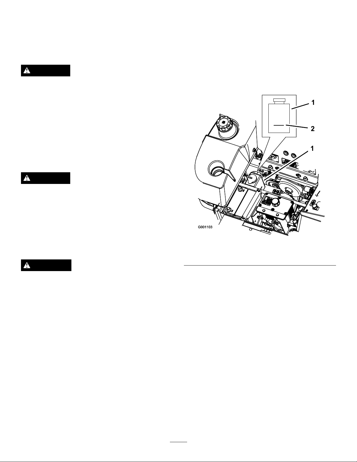
CoolingSystem
Maintenance
ServicingtheCoolingSystem
3.Withtheenginecool,checktheoverowbottlelevel.
Theuidneedstobeuptothebumpontheoutside
oftheoverowbottle(
4.Ifthecoolantlevelislow,adda50/50mixof
extendedlifeantifreeze/Dex-Cool®andwaterto
theoverowbottle(
Figure64).
Figure64).
DANGER
Dischargeofhotpressurizedcoolantortouching
hotradiatorandsurroundingpartscancausesevere
burns.
•Donotremovetheradiatorcapwhentheengine
ishot.Alwaysallowtheenginetocoolatleast
15minutesoruntiltheradiatorcapiscool
enoughtotouchwithoutburningyourhand
beforeremovingtheradiatorcap.
•Donottouchradiatorandsurroundingparts
thatarehot.
DANGER
Rotatingshaftandfancancausepersonalinjury.
•Donotoperatethemachinewithoutthecovers
inplace.
•Keepngers,handsandclothingclearof
rotatingfananddriveshaft.
•Shutofftheengineandremovetheignitionkey
beforeperformingmaintenance.
5.Addthe50/50coolantmixtotheoverow
bottleandllittotheindicatorlineonthebottle
Figure64).
(
Figure64
1.Antifreezeoverowbottle2.Indicatorlineonsideof
overowbottle
CAUTION
Swallowingenginecoolantcancausepoisoning.
•Donotswallowenginecoolant.
•Keepoutofreachfromchildrenandpets.
CheckingtheRadiatorCoolant
ServiceInterval:Beforeeachuseordaily
Aftertherst8hours
Every100hours
FluidType:50/50mixofextendedlife
antifreeze/Dex-Cool®andwater
CoolingSystemCapacity:176ounces(4.6l)
Note:Donotopentheradiatorcap.Doingthismay
induceairintothecoolingsystem.
1.Positionthemachineonalevelsurface,stopthe
engine,andsettheparkingbrake.
2.Unlatchtheseatandtilttheseatup.
CleaningtheHydraulicOilCoolerand
RadiatorScreen
ServiceInterval:Beforeeachuseordaily
Beforeeachuse,checkandcleantheradiatorscreen
andoilcooler.Removeanybuild-upofgrass,dirtor
otherdebrisfromtheoilcoolerandradiatorscreenwith
compressedair(Figure65).
47
Page 48
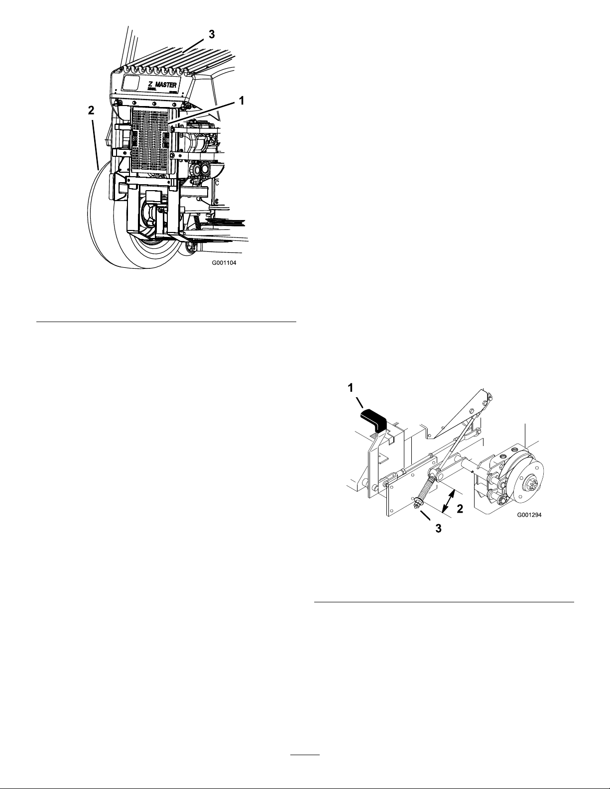
Figure65
1.Hydraulicoilcooler3.Radiatorscreen
2.Leftreartire
BrakeMaintenance
AdjustingtheParkingBrake
ServiceInterval:Every25hours
Every200hours
1.Engagetheparkingbrake,leverup.
2.Measurethelengthofthespring.Measurement
shouldbe2-1/2inch(64mm)betweenthewashers
(Figure66).
3.Ifadjustmentisnecessary,releasetheparkingbrake,
loosenthejamnutbelowthespringandadjustthe
nutdirectlybelowthespring(
nutuntilthecorrectmeasurementisobtained.Turn
thenutclockwisetoshortenspringlengthandturn
counter-clockwisetolengthenthespring.
4.Tightenthetwonutstogether.
5.Engagetheparkingbrake,leverup.Checkthe
measurementofthespringagain.
Figure66).Turnthe
ChangingtheEngineCoolant
ServiceInterval:Yearly
ContactanAuthorizedServiceDealerforchangingthe
coolant.
6.Ifadjustmentisnecessary,repeattheprocedures
above.
7.Repeatontheoppositesideofmachine.
Figure66
1.Brakeleverinengaged
position
2.Spring2–1/2inch(64mm)
3.Adjustingnutandjamnut
48
Page 49
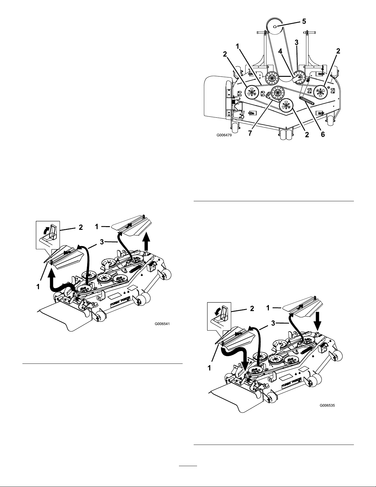
BeltMaintenance
InspectingtheBelts
ServiceInterval:Every100hours
Checkbeltsforcracks,frayededges,burnmarks,orany
otherdamage.Replacedamagedbelts.
ReplacingtheMowerBelt
Squealingwhenthebeltisrotating,bladesslippingwhen
cuttinggrass,frayedbeltedges,burnmarksandcracks
aresignsofawornmowerbelt.Replacethemowerbelt
ifanyoftheseconditionsareevident.
1.DisengagethePTO,movethemotioncontrollevers
totheneutrallockedpositionandsettheparking
brake.
2.Stoptheengine,removethekey,andwaitforall
movingpartstostopbeforeleavingtheoperating
position.
Figure68
1.Mowerbelt
2.Mowerspindlepulley6.Idlerspring
3.Springloadedidlerpulley7.Idlerplate(for72inch
4.Beltguideata45degree
angle
5.Gearboxpulley
mowersonly)
3.Removethebeltcovers(
1.Beltcover3.Insertslotintothetab
2.Latch
Figure67).
Figure67
4.For72inchmowers,loosentheidlerplatebolts
holdingtheidlerplate(Figure70).
9.Installthebeltguideonthespringloadedidlerata
45degreeangleasshowninFigure68andFigure70.
Torquetheboltto27to33ft-lb(37to45N-m).
10.Installtheidlerspringtothetwoposts(Figure68
andFigure70).
11.For72inchmowers,adjustthebelttension,referto
AdjustingtheMowerBeltTension.
12.Installthebeltcoversbyslidingthecoverintothe
tab,installthebolts,andclosethelatches(
Figure69).
5.Removetheidlerspring.
6.Removethebeltguideonthespringloadedidler
pulleyshownin
Figure68andFigure70.
7.Removetheexistingbelt.
8.Installthenewbeltaroundthemowerpulleysand
thegearboxpulleyundertheengine(Figure68).
Figure69
1.Beltcover3.Insertslotintothetab
2.Latch
49
Page 50
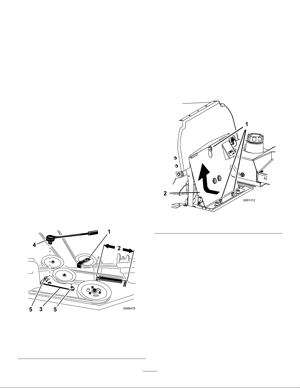
AdjustingtheMowerBelt
ReplacingthePTODriveBelt
Tensionfor72inMowersOnly
ServiceInterval:Aftertherst8hours
Important:Toensurepropermowerbelttension,
whichwillresultinalongerbeltlife,checkthe
mowerbelttensionaftertherst8hoursofuseand
8hoursaftereachbeltchange.
1.DisengagethePTO,movethemotioncontrollevers
totheneutrallockedposition,andsettheparking
brake.
2.Stoptheengine,removethekey,andwaitforall
movingpartstostopbeforeleavingtheoperating
position.
3.Adjustthemowerdecktothe3inch(76mm)
height-of-cutposition.
4.Measurethespringlength(
lengthisbetween10and10-1/4inches(25.4and
26.0cm),fromposttopost,noadjustmentisneeded.
5.Loosentheboltsholdingtheidlerplate(Figure70).
6.Insertaratchetorbreakerbarintothesquareholein
theidlerplatetoadjustthetension(
Figure70).Ifthespring
Figure70).
ServiceInterval:Every50hours—CheckthePTO
drivebelt.
1.DisengagethePTO,movethemotioncontrollevers
totheneutrallockedpositionandsettheparking
brake.
2.Stoptheengine,removethekey,andwaitforall
movingpartstostopbeforeleavingtheoperating
position.
3.Loosenthefrontenginepanelknobsandremove
thepanel(
Figure71).
7.Rotatetheratchetorbreakerbartomovetheidler
plateuntiltheidlerspringisbetween10and10-1/4
inches(25.4and26.0cm)fromposttopostas
showninFigure70.
8.Whileholdingthebelttensionandspringlength,
tightentheidlerplateboltsthatsecuretheidlerplate
Figure70).
(
Figure70
1.Beltguideinstallata45
degreeangle
2.Idlerspringlength
(between10and10-1/4
inches(25.4and26.0cm))
3.Idlerplate
4.Ratchetorbreakerbar
5.Idlerplatebolt
Figure71
1.Knob2.Frontenginepanel
4.Removethespringfromtheidlerarm(Figure72).
5.Removetheclutchstopbracket.
6.RemovetheoldPTOdrivebelt.
7.InstallthePTOdrivebeltaroundtheclutchpulley
andthegearboxpulley(
Figure72).
8.Intalltherubberclutchstop.
9.Installthespringtotheidlerarm(
Figure72).
50
Page 51
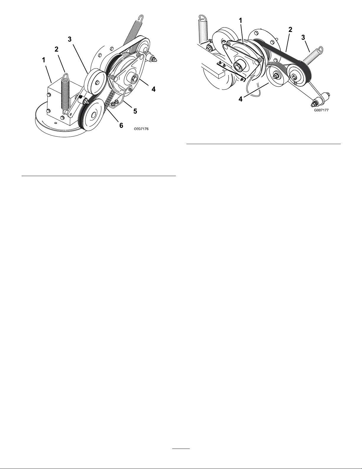
Figure72
1.Gearbox4.Clutch
2.Spring
3.Springloadedidlerpulley6.PTODrivebelt
5.Rubberclutchstop
Figure73
1.Clutch3.Spring
2.Pumpdrivebelt
4.Springloadedidlerpulley
ReplacingandTensioningthe
AlternatorBelt
ReplacingthePumpDriveBelt
ServiceInterval:Every50hours—Checkthepump
drivebelt.
Note:RemovethePTOdrivebeltrstifthepump
drivebeltneedstobereplaced.
1.Tilttheseatforwardandremovethefrontengine
panel.
2.RemovethePTOdrivebelt.
3.Removethespringfromtheidlerarm(
4.Installthenewbeltaroundtheengineandhydro
pumppulley(
Figure73).
5.InstallthePTOdrivebelt.
6.Installthespringtotheidlerarm(Figure73).
Figure73).
ReplacingtheAlternatorBelt
ServiceInterval:Every50hours—Checkthealternator
belt.
1.DisengagethePTO,movethemotioncontrollevers
totheneutrallockedpositionandsettheparking
brake.
2.Stoptheengine,removethekey,andwaitforall
movingpartstostopbeforeleavingtheoperating
position.
3.Removethe4boltsholdingtheoilcoolershieldto
therearframe(
4.Removethe3boltsholdingtheenginestrapstothe
sideofthemachine(Figure74).
Figure74).
51
Page 52
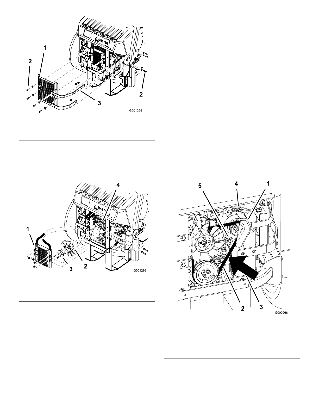
1.Oilcoolershield
2.Bolts
Figure74
3.Enginestraps
12.Installtheoilcoolershieldandenginestrapsto
therearframewiththe4boltspreviouslyremoved
(Figure74).
13.Installtheenginestrapstothesideofthemachine
Figure74).
(
14.Tightenthebottomboltandinstalltheupperbolt
holdingthealternatorandcover(Figure76).
TensioningtheAlternatorBelt
1.Placeahandlebetweenthealternatorandcylinder
block.
2.Adjustthealternatortotheoutsideuntilthereis
1/4to11/32inch(7to9mm)deectioninthebelt
betweentheengineandthealternatorpulleyswith
22.1lbsofforce(10kgf)(
3.Tightenthealternatorbolts.
Figure76).
5.Removethe4boltsholdingtheoilcoolerand
positiontheoilcoolertotheside(Figure75).
6.Removethe2boltsholdingthefanandfanplateto
themachine(Figure75).
Figure75
1.Oilcooler
2.Fan4.Alternatorbelt
3.Fanplate
4.Checkthedeectioninthebeltagainandadjustthe
beltifneeded.
5.Ifthedeectioniscorrect,tightenthebottomand
upperbolt(
Figure76).
7.Loosenthebottomboltandremovetheupperbolt
holdingthealternatorandcover(Figure76).
8.Rotatethealternatorcovertothesideandremove
thebeltfromthepulleysandalternator.
9.Installanewbeltaroundthepulleysandthe
alternator(Figure76).
10.Installthefanandfanplatetothemachinewiththe
2boltspreviouslyremoved(Figure75).
11.Installtheoilcoolerwiththe4boltspreviously
removed(
Figure75).
Figure76
1.Alternator4.Topbolt
2.Alternatorbelt5.Bottombolt
3.Deection,1/4to
11/32inch(7to9mm)with
22.1lbsofforce(10kgf)
52
Page 53
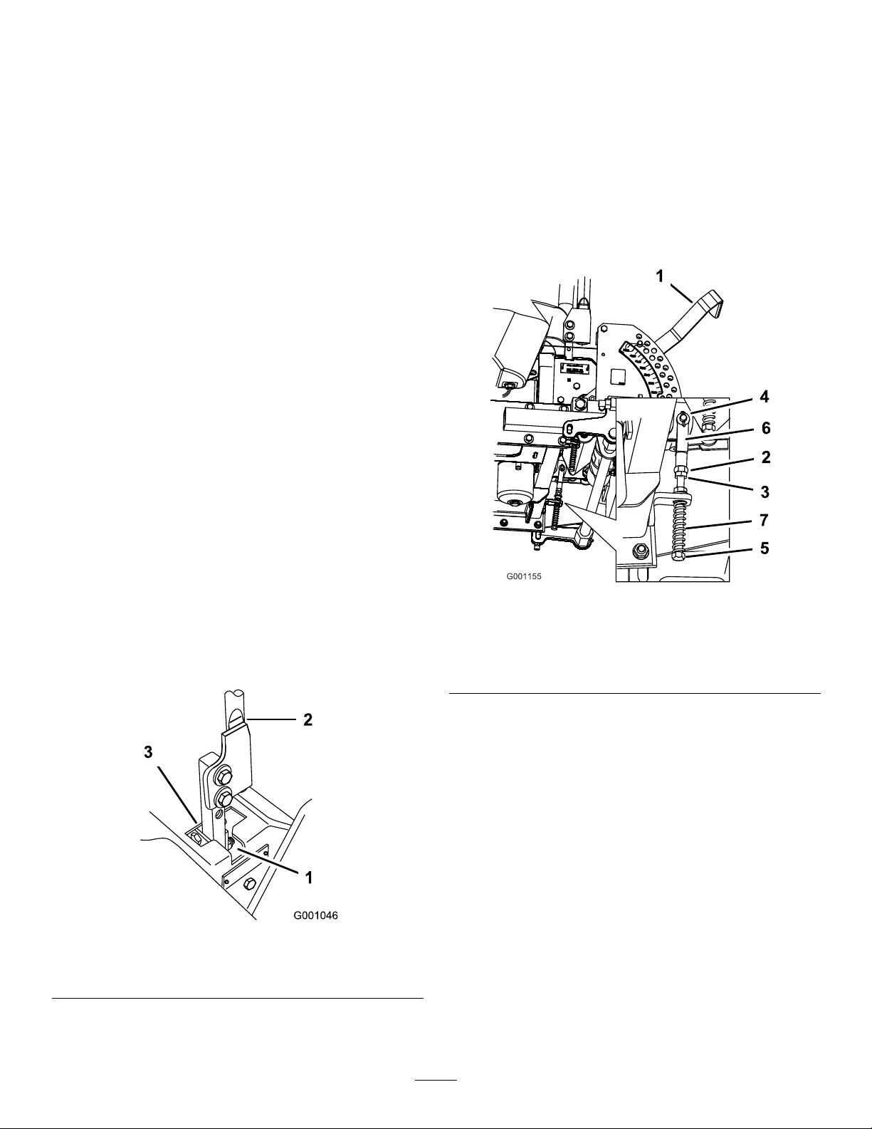
ControlsSystem
Maintenance
9.Applyslightrearwardpressureonthemotion
controllever,turntheheadoftheadjustmentbolt
intheappropriatedirectionuntilthecontrolleveris
centeredintheneutrallockposition(
Figure78).
AdjustingtheControlHandle
NeutralPosition
Ifmotioncontrolleversdonotalign,ormoveeasilyinto
theconsolenotch,adjustmentisrequired.Adjusteach
lever,springandrodseparately.
Note:Motioncontrolleversmustbeinstalledcorrectly.
SeeInstallingtheMotionControlLeversinthesetup
instructions.
1.DisengagethePTO,movethemotioncontrollevers
totheneutrallockedpositionandsettheparking
brake.
2.Stoptheengine,removethekey,andwaitforall
movingpartstostopbeforeleavingtheoperating
position.
3.Unlatchtheseatandtilttheseatforward.
4.Beginwitheithertheleftorrightmotioncontrol
lever.
5.Movethelevertotheneutralpositionbutnotlocked
(Figure77).
Note:Keepingrearwardpressureontheleverwill
keepthepinattheendoftheslotandallowthe
adjustmentbolttomovethelevertotheappropriate
position.
10.Tightenthenutandjamnut(Figure78).
11.Repeatfortheoppositesideofthemachine.
6.Pulltheleverbackuntiltheclevispin(onarm
belowpivotshaft)contactstheendoftheslot(just
beginningtoputpressureonthespring)(Figure77).
7.Checkwherethecontrolleverisrelativetonotchin
console(
levertopivotoutwardtotheneutrallockposition.
1.Neutrallockedposition3.Neutralposition
2.Controllever
Figure77).Itshouldbecenteredallowing
Figure77
Figure78
1.Height-of-cutlever
2.Nutagainstyoke6.Yoke
3.JamNut
4.Clevispininslot
5.Adjustmentbolt
7.Spring
8.Ifadjustmentisneeded,loosenthenutandjamnut
againsttheyoke(Figure78).
53
Page 54
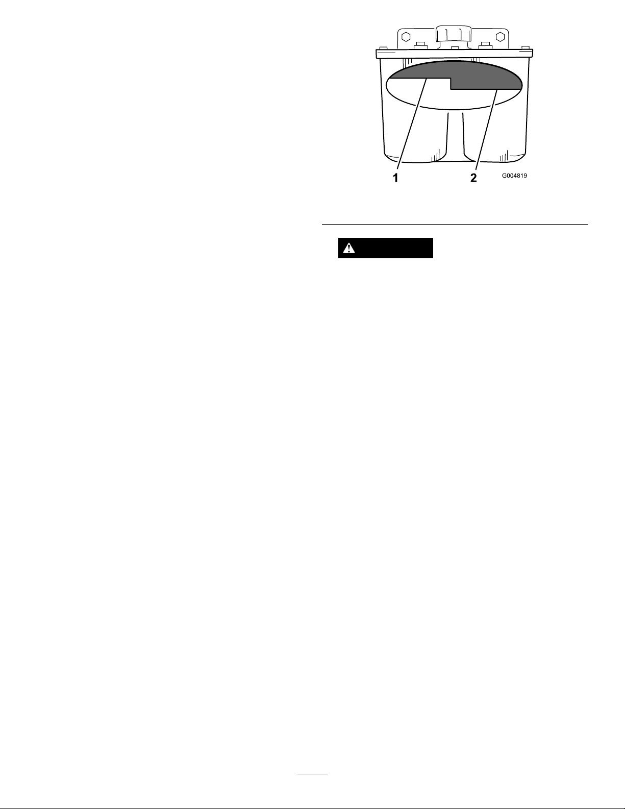
HydraulicSystem
Maintenance
ServicingtheHydraulic
System
HydraulicOilType:Toro
hydraulicoilorMobil
HydraulicSystemOilCapacity:132ounces(3.9l)
Important:Useoilspecied.Otheruidscould
causesystemdamage.
®
®
115W-50oil
HYPR-OIL
™
500
CheckingtheHydraulicFluidLevel
ServiceInterval:Aftertherst8hours
Every25hours
Note:Therearetwowaysofcheckingthehydraulicoil.
Oneiswhentheoiliswarmandoneiswhentheoilis
cold.Thebafeinsidethetankhastwolevelsdepending
iftheoiliswarmorcold.
1.Positionthemachineonalevelsurfaceandsetthe
parkingbrake.
2.Cleantheareaaroundllerneckofhydraulictank
Figure79).
(
3.Removethecapfromthellerneck.Lookinsideto
checkifthereisuidinthereservoir(
4.Ifthereisnouid,adduidtothereservoiruntilit
reachesthecoldlevelofthebafe.
5.Runthemachineatlowidlefor15minutestoallow
anyairtopurgeoutofthesystemandwarmthe
uid.RefertoStartingandStoppingtheEnginein
StartingandStoppingtheEngine(page19).
6.Rechecktheuidlevelwhiletheuidiswarm.The
uidshouldbebetweencoldandhot.
Figure79).
Figure79
1.Hotuidlevel-full2.Colduidlevel-full
WARNING
Hydraulicuidescapingunderpressurecan
penetrateskinandcauseinjury.
•Ifhydraulicuidisinjectedintotheskin
itmustbesurgicallyremovedwithinafew
hoursbyadoctorfamiliarwiththistypeof
injury.Gangrenemayresultifthisisnot
done.
•Keepbodyandhandsawayfrompinhole
leaksornozzlesthatejecthighpressure
hydraulicuid.
•Usecardboardorpapertondhydraulic
leaks.
•Safelyrelieveallpressureinthehydraulic
systembeforeperforminganyworkonthe
hydraulicsystem.
•Makesureallhydraulicuidhosesand
linesareingoodconditionandallhydraulic
connectionsandttingsaretightbefore
applyingpressuretohydraulicsystem.
ReplacingtheHydraulicFilterandOil
7.Ifrequired,adduidtothehydraulictank.
Note:Theuidlevelshouldbetothetopofthehot
levelofthebafe,whentheuidishot(Figure79).
8.Installcaponllerneck.
ServiceInterval:Aftertherst25hours
Every250hours—Changethe
hydrauliclterandhydraulicoilwhen
usingMobil
Every500hours—Changethe
hydrauliclterandhydraulicoil
whenusingToro
hydraulicoil.
Usesummerlterabove32°F(0°C)
Usewinterlterbelow32°F(0°C)
54
®
1oil.
®
HYPR-OIL
™
500
Page 55
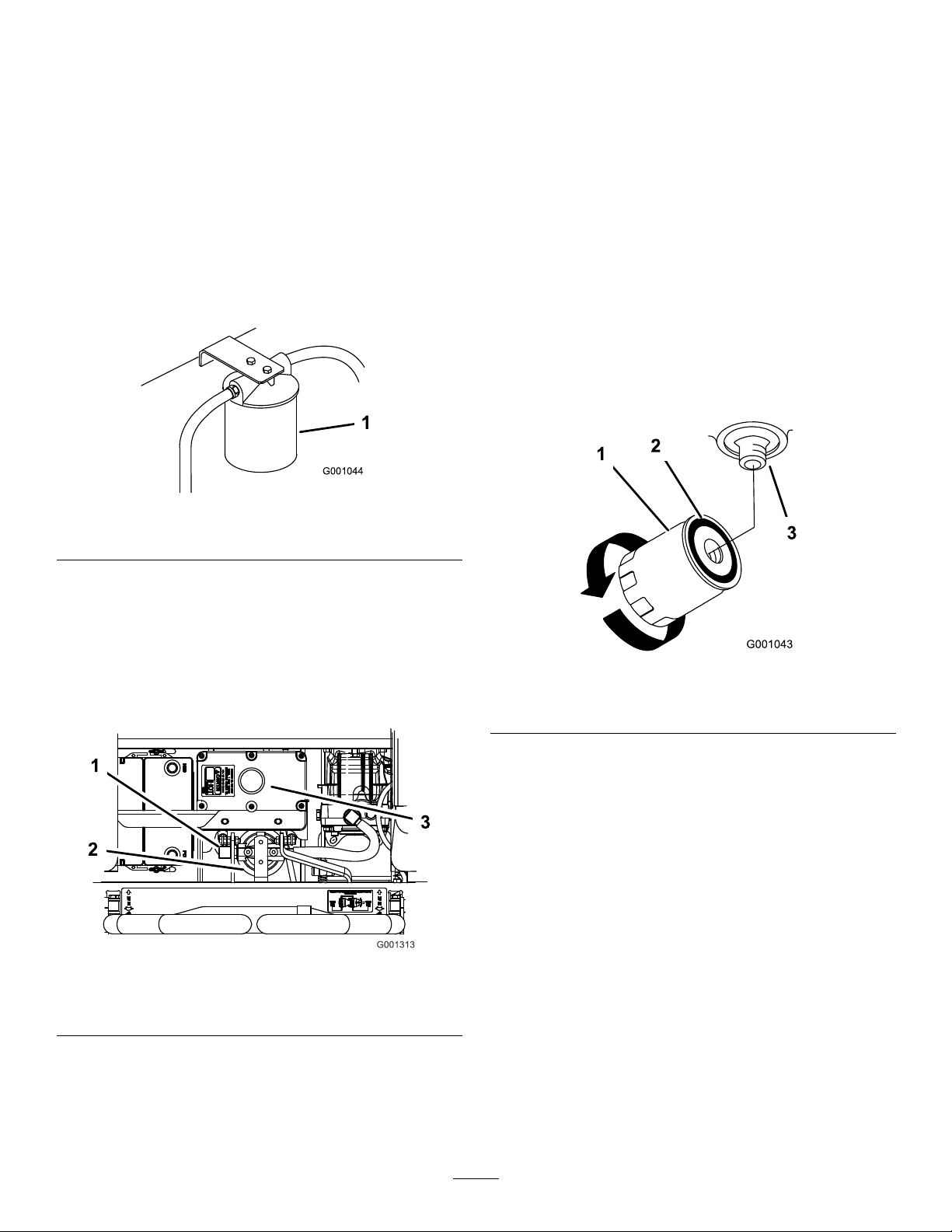
1.DisengagethePTO,movethemotioncontrollevers
totheneutrallockedpositionandsettheparking
brake.
2.Stoptheengine,removethekey,andwaitforall
movingpartstostopbeforeleavingtheoperating
position.
9.Fillthehydraulictankwithhydraulicuiduntilthe
uidoverowsthelterandthenturntheoillter
clockwiseuntiltherubbergasketcontactsthelter
adapter,thentightenthelteranadditional1/2turn
(Figure82).
10.Cleanupanyspilleduid.
Important:Donotsubstituteautomotiveoil
lterorseverehydraulicsystemdamagemay
result.
3.Placedrainpanunderlter,removetheoldlter
andwipethelteradaptergasketsurfaceclean
Figure80).
(
Figure80
1.Hydrauliclter
4.Removetherighthandhydrauliclinethatcomesinto
theadapter(Figure81).
5.Allowtheoiltodrainoutofthesystemintothe
drainpan.
6.Installtherighthandhydrauliclinetotheadapter
Figure81).
(
11.Adduidtothecoldlevelofthebafeinthe
hydraulictank.
12.Starttheengineandletitrunforabouttwominutes
topurgeairfromthesystem.Stoptheengineand
checkforleaks.Ifoneorbothwheelswillnotdrive,
refertoBleedingHydraulicSystem.
13.Rechecktheuidlevelwhiletheuidiswarm.The
uidshouldbebetweencoldandhot.
14.Ifrequired,adduidtothehydraulictank.Donot
overll.
Figure82
1.Hydrauliclter
2.Gasket
3.Adapter
Figure81
1.Righthandhydraulicline3.Hydraulictank
2.Hydrauliclter
7.Applyathincoattotherubbergasketonthe
replacementlter(Figure82).
8.Installthereplacementhydrauliclterontothelter
adapter.Donottighten.
BleedingtheHydraulicSystem
Thetractionsystemisselfbleeding,however,itmaybe
necessarytobleedthesystemifuidischangedorafter
workisperformedonthesystem.
1.Raiserearofthemachinesowheelsareoffthe
groundandsupportwithjackstands.
2.Starttheengineandrunatlowidlespeed.Engage
theleverandtractionononesideandspinthewheel
byhand.
3.Whenthewheelbeginstospinonitsown,keepit
engageduntilwheeldrivessmoothly .(minimum
2minutes)
4.Checkhydraulicuidlevelandaddasrequiredto
maintainproperlevel.
5.Repeatthisprocedureontheoppositewheel.
55
Page 56

CheckingtheHydraulicHoses
ServiceInterval:Every100hours
Checkthehydraulichosesforleaks,loosettings,
kinkedlines,loosemountingsupports,wear,weather
andchemicaldeterioration.Makenecessaryrepairs
beforeoperating.
1.Raisetheframeandblockupthemachinesodrive
wheelscanrotatefreely .
2.Disconnecttheelectricalconnectorfromtheseat
safetyswitch.Temporarilyinstallajumperwire
acrossterminalsinthewiringharnessconnector.
3.Unlatchtheseatandslideseatforward.
Note:Keepareasaroundthehydraulicsystemclean
fromgrassanddebrisbuildup.
WARNING
Hydraulicuidescapingunderpressurecan
penetrateskinandcauseinjury.
•Ifhydraulicuidisinjectedintotheskinit
mustbesurgicallyremovedwithinafewhours
byadoctorfamiliarwiththistypeofinjury.
Gangrenemayresultifthisisnotdone.
•Keepbodyandhandsawayfrompinholeleaks
ornozzlesthatejecthighpressurehydraulic
uid.
•Usecardboardorpapertondhydraulicleaks.
•Safelyrelieveallpressureinthehydraulicsystem
beforeperforminganyworkonthehydraulic
system.
•Makesureallhydraulicuidhosesandlinesare
ingoodconditionandallhydraulicconnections
andttingsaretightbeforeapplyingpressureto
hydraulicsystem.
4.Disconnecttheseatrodandtilttheseatfullyforward.
SettingtheRight-handHydraulicPump
NeutralPosition
1.Starttheengine,openthethrottle1/2wayandrelease
parkingbrake.RefertoStartingandStoppingthe
EngineinStartingandStoppingtheEngine(page19).
Note:Themotioncontrollevermustbeinneutral
whilemakinganyadjustments.
2.Adjustthepumprodlengthbyrotatingtheknob,in
theappropriatedirection,untilthewheelisstillor
slightlycreepinginreverse(
3.Movethemotioncontrolleverforwardandreverse,
thenbacktoneutral.Thewheelmuststopturning
orslightlycreepinreverse.
4.Openthethrottletofast.Makesurewheelremains
stoppedorslightlycreepsinreverse,adjustif
necessary.
Figure83).
SettingtheHydraulicPump
NeutralPosition
Note:Adjustthehandleneutralrst.Thatneedstobe
correctbeforethefollowingadjustmentcanbemade.
Thisadjustmentmustbemadewithdrivewheelsturning.
DANGER
Mechanicalorhydraulicjacksmayfailtosupport
machineandcauseaseriousinjury.
•Usejackstandwhensupportingmachine.
•Donotusehydraulicjacks.
WARNING
Enginemustberunningsomotioncontrol
adjustmentcanbeperformed.Contactwithmoving
partsorhotsurfacesmaycausepersonalinjury.
Keephands,feet,face,clothingandotherbody
partsawayfromrotatingparts,muferandother
hotsurfaces.
56
Page 57
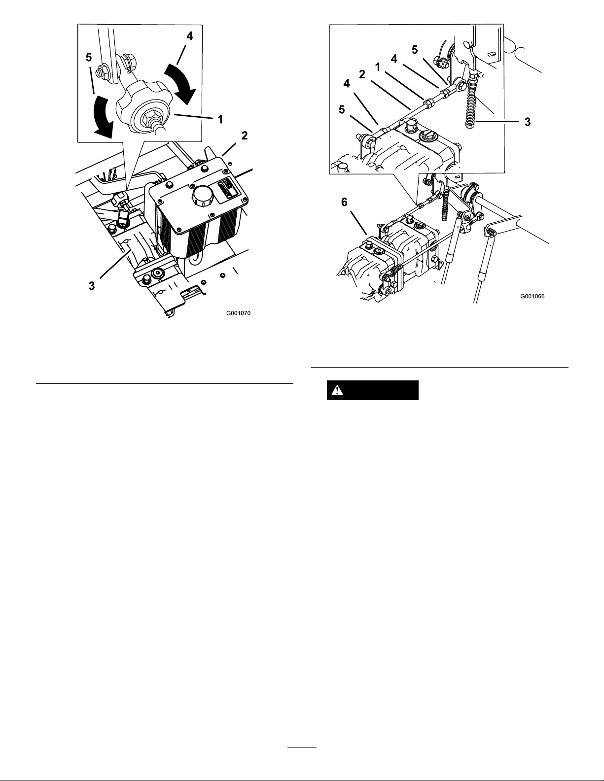
Figure83
1.Trackingknob4.Turnthiswaytotrackright
2.Hydraulictank
3.Hydraulicpumps
5.Turnthiswaytotrackleft
Figure84
1.Doublenuts4.Locknut
2.Pumprod5.Balljoint
3.Adjustmentbolt6.Pumps
WARNING
SettingtheLeft-handHydraulicPump
NeutralPosition
1.Loosenthelocknutsattheballjointsonthepump
controlrod(Figure84).
2.Starttheengine,openthrottle1/2wayandrelease
parkingbrake.RefertoStartingandStoppingthe
Enginein
Note:Themotioncontrollevermustbeinneutral
whilemakinganyadjustments.
Note:Thefrontnutonthepumprodhasleft-hand
threads.
3.Adjustthepumprodlengthbyrotatingdoublenuts
onrod,intheappropriatedirection,untilwheelis
stillorslightlycreepsinreverse(Figure84).
4.Movethemotioncontrolleverforwardandreverse,
thenbacktoneutral.Thewheelmuststopturning
orslightlycreepinreverse.
5.Openthethrottletofast.Makesurethewheel
remainsstoppedorslightlycreepsinreverse,adjust
ifnecessary.
StartingandStoppingtheEngine(page19).
Electricalsystemwillnotperformpropersafety
shutoffwithjumperwireinstalled.
•Removejumperwirefromwireharness
connectorandplugconnectorintoseat
switchwhenadjustmentiscompleted.
•Neveroperatethisunitwithjumperinstalled
andseatswitchbypassed.
7.Afterbothpumpneutralsareset,shutoffthe
machine.
8.Removethejumperwirefromthewireharness
connectorandplugtheconnectorintotheseat
switch.
9.Installtheseatrodandlowertheseatintoposition.
10.Removethejackstands.
6.Tightenthelocknutsattheballjoints(
Figure84).
57
Page 58
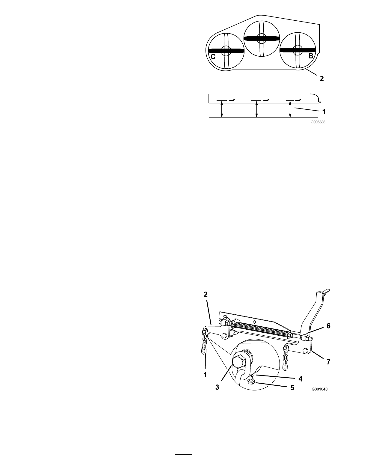
MowerDeck
Maintenance
LevelingtheMoweratThree
Positions
Important:Thereareonlythreemeasuring
positionsneededtolevelthemower.
SettingUptheMachine
1.Positionmoweronaatsurface.
2.DisengagethePTO,movethemotioncontrollevers
totheneutrallockedpositionandsettheparking
brake.
1.Measureherefromblade
tohardsurface
Figure85
2.MeasureatBandC
3.Stoptheengine,removethekey,andwaitforall
movingpartstostopbeforeleavingtheoperating
position.
4.Checktirepressureofallfourtires.Ifneeded,adjust
to13psi(90kPa)
5.Lowerthemowertothe3inch(76mm)height-of-cut
position.
6.Inspectthefourchains.Thechainsneedtohave
tension.
Note:Adjusttherearchainstothetopoftheslot,
wheretheyareattachedtothemower.
•Ifonerearchainisloose,lower(loosen)thefront
supportarmonthesameside.RefertoAdjusting
theFront-to-RearMowerPitch.
•Ifonefrontchainisloose,raise(tighten)the
frontsupportarmforthatchain.Referto
AdjustingtheFront-to-RearMowerPitch.
LevelingtheMowerSide-to-Side
2.MeasuretherightbladeattheBlocation,froma
levelsurfacetothecuttingedgeofthebladetip
(Figure85).
3.Recordthismeasurement.Thismeasurementneeds
tobe3-1/8to3-1/4inches.
4.Positiontheleftbladeside-to-side(Figure85).
5.MeasuretheleftbladeattheClocation(Figure85),
fromalevelsurfacetothecuttingedgeoftheblade
tip.
6.Recordthismeasurement.Thismeasurementneeds
tobe3-1/8to3-1/4inches(80to83mm).
7.IfthemeasurementsatpositionsBorCarenot
correct,loosentheboltattachingtherearchainto
therearsupportarm(Figure86).
1.Positiontherightbladeside-to-side(Figure85).
Figure86
1.Rearchain5.Adjustmentbolt
2.Rearsupportarm6.Frontswivel
3.Bolt7.Frontsupportarm
4.JamNut
58
Page 59
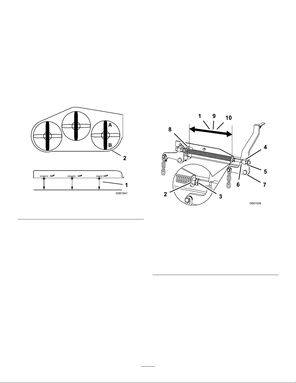
8.Loosenthejamnutundertherearsupportarmand
adjusttheadjustmentbolttogetameasurementof
3-1/8to3-1/4inches(80to83mm)(Figure86).
Note:Itisrecommendedthatbothsidesofthe
mowerareadjustedthesamedistance.
9.Tightenthejamnutundertherearsupportarm
andtightentheboltsecuringthechaintotherear
supportarm.
10.Adjusttheoppositesideifneeded.
AdjustingtheFront-to-RearMower
Pitch
1.Positiontherightbladefront-to-rear(Figure87).
(6to10mm)lowerinfrontatAthanintherearat
B(Figure86).
9.Tightenbothswiveljamnutsagainstthefrontswivel
tolocktheheight.
10.Checktomakesurethereisequaltensiononthe
chainsandadjustagainifneeded.
AdjustingtheCompressionSpring
1.Raisethemowerliftlevertothetransportposition.
2.Checkthedistancebetweenthetwolargewashers,
itneedstobe11-1/8inches(28.2cm)for52inch
mowerdecks,10-1/2inches(26.7cm)for60inch
mowerdecksor11–1/2inches(29.2cm)for72inch
mowerdecks(
Figure88).
Figure87
1.Measureherefromblade
tohardsurface
2.MeasureatAandB
2.MeasuretherightbladeattheAlocation,froma
levelsurfacetothecuttingedgeofthebladetip
(Figure87).
3.Recordthismeasurement.
4.MeasuretherightbladeattheBlocation,froma
levelsurfacetothecuttingedgeofthebladetip
Figure87).
(
5.Recordthismeasurement.
6.Themowerbladeshouldbea1/4to3/8inch
(6to10mm)loweratpositionAthanatposition
B(Figure87).Ifitisnotcorrect,proceedtothe
followingsteps.
Note:Bothofthefrontswivelsneedtobeadjusted
thesameamounttomaintainequalchaintension.
7.Loosenthefrontswiveljamnuts,atthefrontof
therightandleftswivels,approximatelya1/2inch
(13mm)(
Figure86).
8.Adjusttheliftnutsonboththeleftandtheright
sideofthemachinetoachieve1/4to3/8inch
Figure88
1.11–1/8inch(28.2cm)
betweenthelargewashers
for52inchmowerdecks
2.Frontnut7.Frontsupportarm
3.Springjamnut
4.Frontswivel
5.Swiveljamnut10.1 1-1/2inch(29.2cm)
6.Liftnut
8.Largewasher
9.10-1/2inch(26.7cm)
betweenthelargewashers
for60inchmowerdecks
betweenthelargewashers
for72inchmowerdecks
3.Adjustthisdistance,bylooseningthespringjam
nutandturningthenutinfrontofeachspring
(Figure88).Turningthenutclockwisewillshorten
thespring;counter-clockwisewilllengthenthe
spring.
4.Lockthenutintopositionbytighteningthespring
jamnut(Figure88).
ServicingtheCuttingBlades
Maintainsharpbladesthroughoutthecuttingseason
becausesharpbladescutcleanlywithouttearingor
59
Page 60
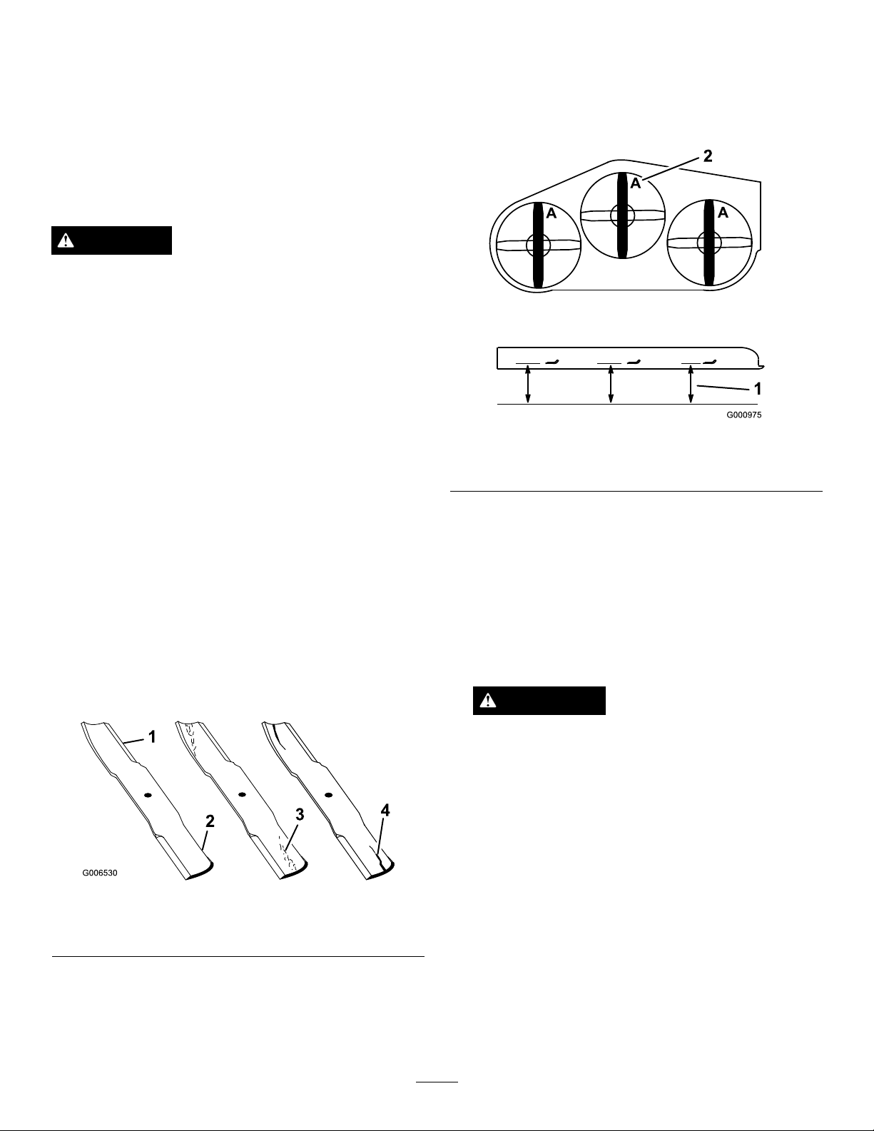
shreddingthegrassblades.Tearingandshreddingturns
grassbrownattheedges,whichslowsgrowthand
increasesthechanceofdisease.
Checkthecutterbladesdailyforsharpness,andforany
wearordamage.Filedownanynicksandsharpenthe
bladesasnecessary.Ifabladeisdamagedorworn,
replaceitimmediatelywithagenuineT ororeplacement
blade.Forconvenientsharpeningandreplacement,you
maywanttokeepextrabladesonhand.
DANGER
Awornordamagedbladecanbreak,andapiece
ofthebladecouldbethrownintotheoperator’s
orbystander’sarea,resultinginseriouspersonal
injuryordeath.
•Inspectthebladeperiodicallyforwearor
damage.
•Replaceawornordamagedblade.
CheckingforBentBlades
1.Rotatethebladesuntiltheendsfaceforwardand
backward(Figure90).Measurefromalevelsurface
tothecuttingedge,positionA,oftheblades
(Figure90).Notethisdimension.
BeforeInspectingorServicingthe
Blades
1.Parkthemachineonalevelsurface,disengagethe
bladecontrol(PTO),andsettheparkingbrake.
2.TurntheignitionkeytoOffandremovethekey.
3.Disconnectthesparkplugwire(s)fromthespark
plug(s).
InspectingtheBlades
ServiceInterval:Beforeeachuseordaily
1.Inspectthecuttingedges(Figure89).
Iftheedgesarenotsharporhavenicks,removeand
sharpentheblades.RefertoSharpeningtheBlades.
Figure90
1.Measureherefromblade
tohardsurface
2.PositionA
2.Rotatetheoppositeendsofthebladesforward.
3.Measurefromalevelsurfacetothecuttingedgeof
thebladesatthesamepositionasinstep1above.
Thedifferencebetweenthedimensionsobtainedin
1and2mustnotexceed1/8inch(3mm).If
steps
thisdimensionexceeds1/8inch(3mm),theblade
isbentandmustbereplaced;refertoRemovingthe
BladesandInstallingtheBlades.
WARNING
Abladethatisbentordamagedcouldbreak
apartandcouldseriouslyinjureorkillyouor
bystanders.
•Alwaysreplacebentordamagedbladewith
anewblade.
•Neverleorcreatesharpnotchesinthe
edgesorsurfacesofblade.
Figure89
1.CuttingEdge3.Wear/slotForming
2.CurvedArea4.Crack
2.Inspecttheblades,especiallythecurvedarea
(Figure89).
Ifyounoticeanydamage,wear,oraslotformingin
thisarea(Figure89),immediatelyinstallanewblade.
RemovingtheBlades
Bladesmustbereplacedifasolidobjectishit,ifthe
bladeisoutofbalanceorisbent.T oensureoptimum
performanceandcontinuedsafetyconformanceof
themachine,usegenuineTororeplacementblades.
Replacementbladesmadebyothermanufacturersmay
resultinnon-conformancewithsafetystandards.
60
Page 61
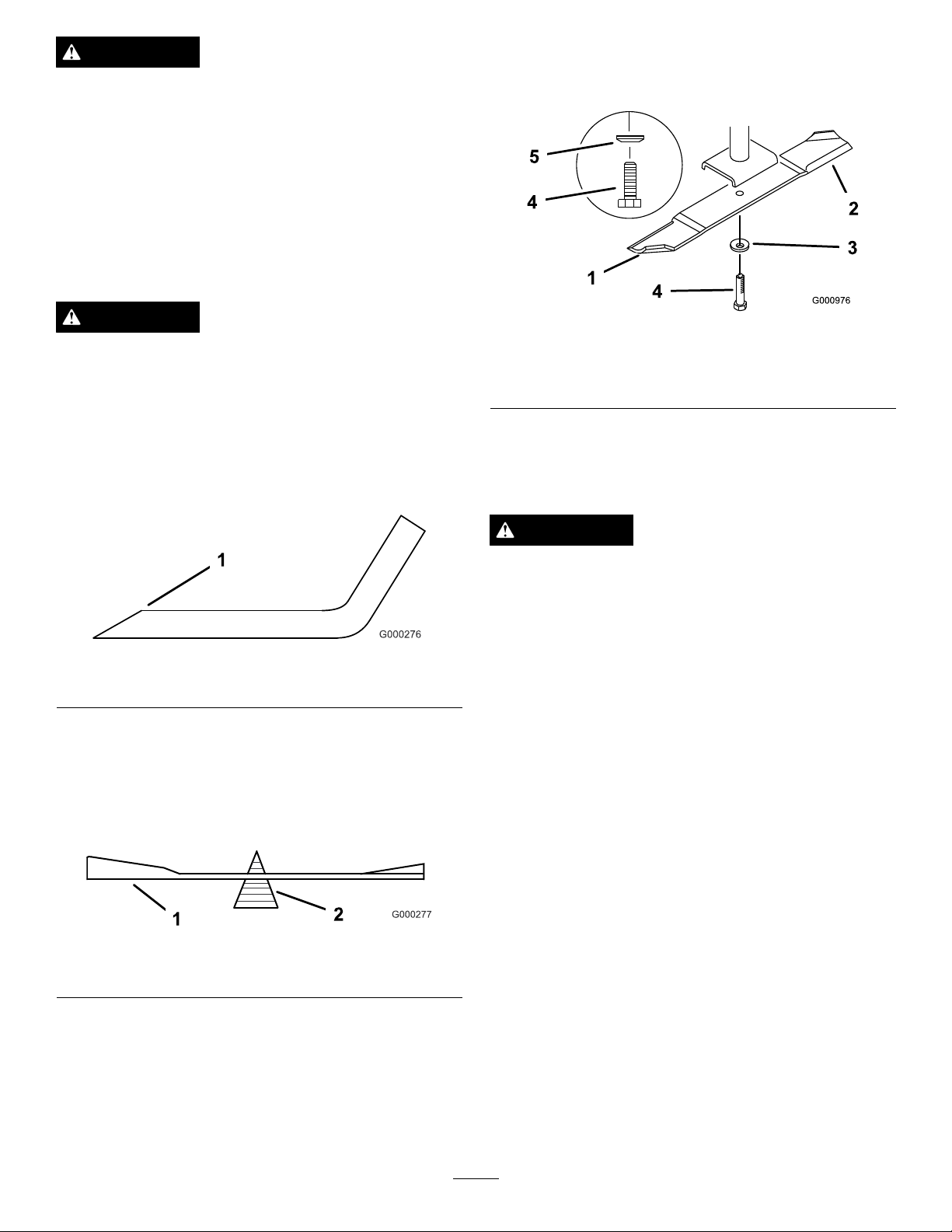
WARNING
Contactwithasharpbladecancauseseriousinjury.
Wearglovesorwrapsharpedgesofthebladewith
arag.
1.Holdthebladeendusingaragorthickly-padded
glove.
2.Removethebladebolt,springdiskandbladefrom
thespindleshaft(Figure93).
SharpeningtheBlades
2.Installthespringdiskandbladebolt.Thespring
diskconemustbeinstalledtowardthebolthead
(Figure93).
WARNING
Whensharpeningblade,piecesofbladecouldbe
thrownandcauseseriousinjury.
Wearpropereyeprotectionwhensharpeningblade.
1.Usealetosharpenthecuttingedgeatbothends
oftheblade(Figure91).Maintaintheoriginalangle.
Thebladeretainsitsbalanceifthesameamountof
materialisremovedfrombothcuttingedges.
Figure91
1.Sharpenatoriginalangle
2.Checkthebalanceofthebladebyputtingitona
bladebalancer(Figure92).Ifthebladestaysina
horizontalposition,thebladeisbalancedandcanbe
used.Ifthebladeisnotbalanced,lesomemetaloff
theendofthesailareaonly(Figure93).Repeatthis
procedureuntilthebladeisbalanced.
Figure93
1.SailAreaofBlade
2.Blade
3.SpringDisk
4.BladeBolt
5.ConeTowardsBoltHead
3.Torquethebladeboltto85-110ft-lb(115-150N⋅m).
ReplacingtheGrassDeector
WARNING
Anuncovereddischargeopeningcouldallowthe
lawnmowertothrowobjectsintheoperator’sor
bystander’sdirectionandresultinseriousinjury.
Also,contactwiththebladecouldoccur.
•Neveroperatethelawnmowerunlessyouinstall
acoverplate,amulchplate,oragrasschuteand
catcher.
•Makesurethegrassdeectorisinthedown
position.
1.Removethelocknut,bolt,springandspacerholding
thedeectortothepivotbrackets(Figure94).
2.Removethedamagedorworngrassdeector.
Figure92
1.Blade2.Balancer
InstallingtheBlades
1.Installthebladeontothespindleshaft(Figure93).
Important:Thecurvedpartoftheblademust
bepointingupwardtowardtheinsideofthe
mowertoensurepropercutting.
3.Placethespacerandspringontothegrassdeector.
PlacetheLendofthespringbehindthedeckedge.
Note:MakesuretheLendofthespringisinstalled
behindthedeckedgebeforeinstallingtheboltas
showninFigure94
4.Installtheboltandnut.
5.PlacetheJhookendofthespringaroundthegrass
deector(Figure94).
Important:Thegrassdeectormustbeableto
lowerdownintoposition.Liftthedeectorup
totestthatitlowersintothefulldownposition.
61
Page 62
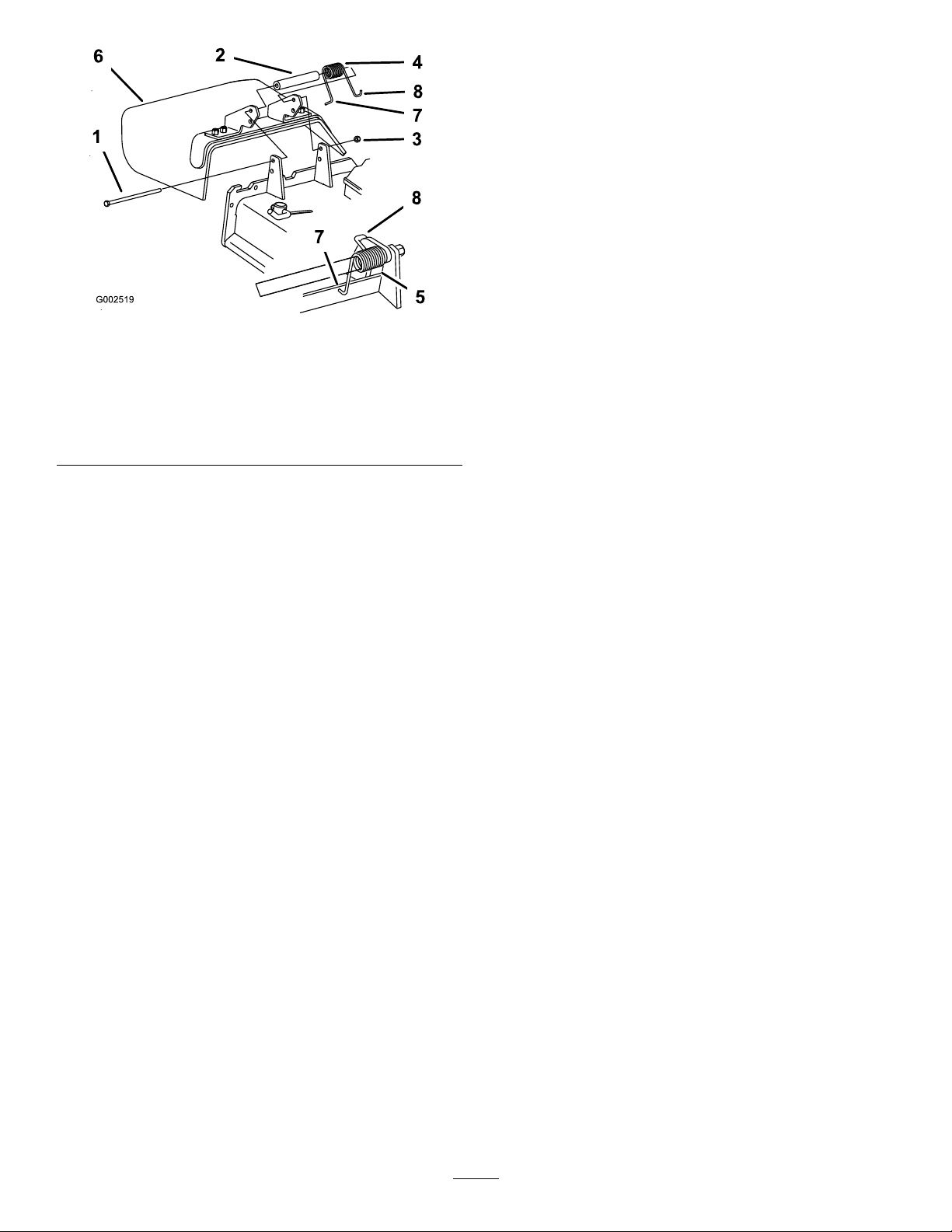
Figure94
1.Bolt
2.Spacer6.GrassDeector
3.Locknut
4.Spring8.Jhookendofspring
5.Springinstalled
7.Lendofspring,place
behinddeckedgebefore
installingbolt
Cleaning
CleaningUndertheMower
ServiceInterval:Beforeeachuseordaily
Removethegrassbuildupunderthemowerdaily.
1.DisengagethePTO,movethemotioncontrollevers
totheneutrallockedpositionandsettheparking
brake.
2.Stoptheengine,removethekey,andwaitforall
movingpartstostopbeforeleavingtheoperating
position.
3.Raisethemowertothetransportposition.
WasteDisposal
Engineoil,batteries,hydraulicoil,andenginecoolant
arepollutantstotheenvironment.Disposeofthese
accordingtoyourstateandlocalregulations.
62
Page 63

Storage
CleaningandStorage
1.Disengagethepowertakeoff(PTO),settheparking
brake,andturntheignitionkeytoOff.Removethe
key.
2.Removegrassclippings,dirt,andgrimefromthe
externalpartsoftheentiremachine,especiallythe
engineandhydraulicsystem.Cleandirtandchaff
fromtheoutsideoftheenginecylinderheadnsand
blowerhousing.
Important:Youcanwashthemachinewith
milddetergentandwater.Donotpressure
washthemachine.Avoidexcessiveuseof
water,especiallynearthecontrolpanel,engine,
hydraulicpumps,andmotors.
3.Checkthebrake;refertoServicingtheBrakein
BrakeMaintenance(page48).
4.Servicetheaircleaner;refertoServicingtheAir
Cleanerin
EngineMaintenance(page35).
C.Restarttheengineandrunituntilitstops.
D.Disposeoffuelproperly.Recycleasperlocal
codes.
Important:Donotstore
stabilizer/conditionedfuelover90days.
13.Checkandtightenallbolts,nuts,andscrews.Repair
orreplaceanypartthatisdamaged.
14.Paintallscratchedorbaremetalsurfaces.Paintis
availablefromyourAuthorizedServiceDealer.
15.Storethemachineinaclean,drygarageorstorage
area.Removethekeyfromtheignitionswitchand
keepitoutofreachofchildrenorotherunauthorized
users.Coverthemachinetoprotectitandkeepit
clean.
5.Greasethemachine;refertoGreasingand
LubricationinLubrication(page32).
6.Changethecrankcaseoil;refertoServicingthe
EngineOilin
7.Checkthetirepressure;refertoCheckingtheTire
PressureinDriveSystemMaintenance(page43).
8.Changethehydrauliclter;referto
ServicingtheHydraulicSystemin
HydraulicSystemMaintenance(page54).
9.Chargethebattery;refertoServicingtheBatteryin
ElectricalSystemMaintenance(page41).
10.Scrapeanyheavybuildupofgrassanddirtfromthe
undersideofthemower,thenwashthemowerwith
agardenhose.
Note:RunthemachinewiththePTOengaged
andtheengineathighidlefor2to5minutesafter
washing.
11.Checktheconditionoftheblades;
refertoServicingtheCuttingBladesin
MowerDeckMaintenance(page58).
EngineMaintenance(page35).
12.Preparethemachineforstoragewhennon-use
occursover30days.Preparethemachineforstorage
asfollows:
A.Runtheenginetodistributeconditionedfuel
throughthefuelsystem(5minutes).
B.Stoptheengine,allowittocool,anddrainthe
fueltank;refertoServicingtheFuelTankin
FuelSystemMaintenance(page39).
63
Page 64

Troubleshooting
Problem
Starterdoesnotcrank
Enginewillnotstart,startshard,orfails
tokeeprunning.
Enginelosespower.
PossibleCauseCorrectiveAction
1.Bladecontrol(PTO)isengaged.1.Movebladecontro(PTO)to
2.Parkingbrakeisnoton.
3.Operatorisnotseated.3.Sitontheseat.
4.Batteryisdead.
5.Electricalconnectionsarecorrodedor
loose.
6.Fuseisblown.
7.Relayorswitchisdefective.7.ContactanAuthorizedServiceDealer .
1.Fueltankisempty.
2.Aircleanerisdirty.
3.Dirtorwaterinthefuellter.3.Replacethefuellter.
4.Dirt,water,orstalefuelisinthefuel
system.
1.Engineloadisexcessive.1.Reducethegroundspeed.
2.Aircleanerisdirty.
3.Oillevelinthecrankcaseislow.
4.Coolingnsandairpassagesabove
theengineareplugged.
5.V entholeinthefuelcapisplugged.5.Cleanorreplacethefuelcap.
6.Dirtorwaterinthefuellter.6.Replacethefuellter.
7.Dirt,water,orstalefuelisinthefuel
system.
disengaged.
2.Settheparkingbrake.
4.Chargethebattery .
5.Checktheelectricalconnectionsfor
goodcontact.
6.Replacefuse.
1.Fillfueltankwithfuel.
2.Cleanorreplacetheaircleaner
element.
4.ContactanAuthorizedServiceDealer .
2.Cleantheaircleanerelement.
3.Addoiltothecrankcase.
4.Removetheobstructionfromthe
coolingnsandairpassages.
7.ContactanAuthorizedServiceDealer .
Engineoverheats.
Machinedoesnotdrive.
Abnormalvibration.
1.Engineloadisexcessive.1.Reducethegroundspeed.
2.Oillevelinthecrankcaseislow.
3.Coolingnsandairpassagesabove
theengineareplugged.
4.Theelectricfandoesnothavepower
orisnotfunctioningcorrectly .
1.Bypassvalveisnotclosedtight.1.Tightenthebypassvalve.
2.Driveorpumpbeltisworn,looseor
broken.
3.Driveorpumpbeltisoffapulley .3.Changethebelt.
4.Brokenormissingidlerspring.4.Replacethespring.
5.Hydraulicuidlevelislowortoohot.5.Addhydraulicuidtoreservoirorletit
1.Cuttingblade(s)is/arebentor
unbalanced.
2.Blademountingboltisloose.2.Tightentheblademountingbolt.
3.Enginemountingboltsareloose.3.Tightentheenginemountingbolts.
4.Looseenginepulley,idlerpulley ,or
bladepulley .
5.Enginepulleyisdamaged.
6.Bladespindleisbent.
7.Motormountislooseorworn.
2.Addoiltothecrankcase.
3.Removetheobstructionfromthe
coolingnsandairpassages.
4.Checkforblown40Afanfuse.Contact
anAuthorizedServiceDealer.
2.Changethebelt.
cooldown.
1.Installnewcuttingblade(s).
4.Tightentheappropriatepulley.
5.ContactanAuthorizedServiceDealer .
6.ContactanAuthorizedServiceDealer .
7.ContactanAuthorizedServiceDealer .
64
Page 65

Problem
PossibleCauseCorrectiveAction
Unevencuttingheight.
Bladesdonotrotate.
1.Blade(s)notsharp.1.Sharpentheblade(s).
2.Cuttingblade(s)is/arebent.2.Installnewcuttingblade(s).
3.Mowerisnotlevel.
4.Undersideofmowerisdirty.4.Cleantheundersideofthemower .
5.Tirepressureisnotcorrect.5.Adjustthetirepressure.
6.Bladespindlebent.
1.Drivebeltisworn,looseorbroken.
2.Drivebeltisoffpulley.
3.Deckbeltisworn,looseorbroken.3.Installnewdeckbelt.
4.Deckbeltisoffpulley.
5.Brokenormissingidlerspring.5.Replacethespring.
3.Levelmowerfromside-to-sideand
front-to-rear.
6.ContactanAuthorizedServiceDealer .
1.Checkthebelttension.
2.Installdrivebeltandcheckadjusting
shaftsandbeltguidesforcorrect
position.
4.Installdeckpulleyandchecktheidler
pulley,idlerarmandspringforcorrect
positionandfunction.
65
Page 66
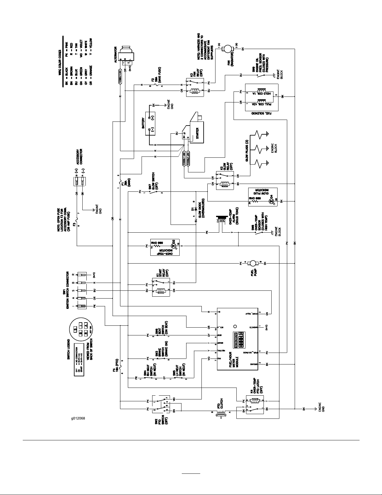
Schematics
g012068
WireDiagram(Rev.A)
66
Page 67

Notes:
67
Page 68

TheToroTotalCoverageWarranty
ALimitedWarranty(seewarrantyperiodsbelow)
Landscape
Contractor
Equipment(LCE)
ConditionsandProductsCovered
TheToroCompanyanditsafliate,ToroWarrantyCompany,pursuantto
anagreementbetweenthem,jointlypromisetotheoriginalpurchaser
torepairtheToroProductslistedbelowifdefectiveinmaterialsor
workmanship.
Thefollowingtimeperiodsapplyfromthedateofpurchasebytheoriginal
owner:
ProductsWarrantyPeriod
AllMowers
•Engine**
•Battery1year
•Attachments1year
Mid-SizeWalk-BehindMowers
GrandStand
•Frame
ZMaster
•Engine
•Frame
ZMaster
•Frame
*Whicheveroccursrst.
**SomeenginesusedonToroLCEProductsarewarrantedbytheenginemanufacturer.Kawasaki
FXengineshavea3yearwarrantytermforresidentialuse.Residentialusemeansuseofthe
productonthesamelotasyourhome.
***LifetimeFrameWarranty-Ifthemainframe,consistingofthepartsweldedtogethertoformthe
tractorstructurethatothercomponentssuchastheenginearesecuredto,cracksorbreaksin
normaluse,itwillberepairedorreplaced,atToro’ soption,underwarrantyatnocostforparts
andlabor .Framefailureduetomisuseorabuseandfailureorrepairrequiredduetorustor
corrosionarenotcovered.
Thiswarrantyincludesthecostofpartsandlabor,butyoumustpay
transportationcosts.
TM
Mowers5yearsor1,200hours*
®
Z400,Z500Mowers
®
G3Mowers5yearsor1,200hours*
2years
2years
Lifetime(originalowneronly)***
4yearsor1,200hours*
2years**
Lifetime(originalowneronly)***
Lifetime(originalowneronly)***
InstructionsforObtainingWarrantyService
IfyouthinkthatyourT oroProductcontainsadefectinmaterialsor
workmanship,followthisprocedure:
1.ContactanyAuthorizedToroServiceDealertoarrangeserviceattheir
dealership.Tolocateadealerconvenienttoyou,refertotheY ellow
Pagesofyourtelephonedirectory(lookunder“LawnMowers”)or
accessourwebsiteatwww.T oro.com.Youmayalsocallthenumbers
listedinitem#3tousethe24-hourToroDealerlocatorsystem.
2.Bringtheproductandyourproofofpurchase(salesreceipt)tothe
ServiceDealer.Thedealerwilldiagnosetheproblemanddetermine
ifitiscoveredunderwarranty.
3.IfforanyreasonyouaredissatisedwiththeServiceDealer’s
analysisorwiththeassistanceprovided,contactusat:
RLCCustomerCareDepartment
ToroW arrantyCompany
811 1LyndaleAvenueSouth
Bloomington,MN55420-1196
888-865-5676(U.S.Customers)
888-865-5691(Canadacustomers)
OwnerResponsibilities
YoumustmaintainyourT oroProductbyfollowingthemaintenance
proceduresdescribedintheOperator’sManual.Suchroutine
maintenance,whetherperformedbyadealerorbyyou,isatyourexpense.
ItemsandConditionsNotCovered
Thereisnootherexpresswarrantyexceptforspecialemission
systemandenginewarrantycoverageonsomeproducts.
Thisexpresswarrantydoesnotcoverthefollowing:
•Costofregularmaintenanceserviceorwearparts,suchaslters,
fuel,lubricants,tune-upparts,bladesharpening,brakeandclutch
adjustments.
•Anyproductorpartwhichhasbeenalteredormisusedandrequires
replacementorrepairduetonormalwear,accidents,orlackof
propermaintenance.
•Repairsnecessaryduetoimproperfuel,contaminantsinthefuel
system,orfailuretoproperlypreparethefuelsystempriortoany
periodofnon-useoverthreemonths.
•Pickupanddeliverycharges.
GeneralConditions
Allrepairscoveredbythesewarrantiesmustbeperformedbyan
AuthorizedToroServiceDealerusingToroapprovedreplacementparts.
NeitherTheToroCompanynorToroWarrantyCompanyisliablefor
indirect,incidentalorconsequentialdamagesinconnectionwiththe
useoftheT oroProductscoveredbythiswarranty,includingany
costorexpenseofprovidingsubstituteequipmentorserviceduring
reasonableperiodsofmalfunctionornon-usependingcompletion
ofrepairsunderthiswarranty.
Allimpliedwarrantiesofmerchantability(thattheproductistfor
ordinaryuse)andtnessforuse(thattheproductistforaparticular
purpose)arelimitedtothedurationoftheexpresswarranty
Somestatesdonotallowexclusionsofincidentalorconsequential
damages,orlimitationsonhowlonganimpliedwarrantylasts,so
theaboveexclusionsandlimitationsmaynotapplytoyou.
Thiswarrantygivesyouspeciclegalrights,andyoumayalsohaveother
rightswhichvaryfromstatetostate.
CountriesOtherthantheUnitedStatesorCanada
CustomerswhohavepurchasedToroproductsoutsidetheUnitedStatesorCanadashouldcontacttheirToroDistributor(Dealer)toobtainguarantee
policiesforyourcountry,province,orstate.IfforanyreasonyouaredissatisedwithyourDistributor’sserviceorhavedifcultyobtainingguarantee
information,contacttheToroimporter.Ifallotherremediesfail,youmaycontactusatT oroWarrantyCompany.
374-0252RevA
 Loading...