

Page 1

LCE Products
Z580/Z589 DFI Z Master
Service Manual
Page 2

ABOUT THIS MANUAL
This service manual was written expressly for Toro service technicians. The Toro Company has made every effort to
make the information in this manual complete and correct.
Basic shop safety knowledge and mechanical/electrical skills are assumed. The Table of Contents lists the systems
and the related topics covered in this manual.
The following service materials are available in addition to this service manual:
Hydrostatic Pumps: Hydro-Gear P Series Pumps - Service and Repair Manual
Form #BLN 52503
Wheel Motors: Hydro-Gear HGM-E Wheel Motor Service Manual
Form #492-9139
Engine: Kawasaki FD791D Engine Service Manual (available through Kawasaki)
Form #99924-2061-03
Hydraulic Troubleshooting: Interactive hydraulic troubleshooting and failure analysis on DVD
Form #492-4777
Electrical Troubleshooting: Interactive electrical troubleshooting and wiring diagrams on DVD
Form # 492-9193
The Z Master Z580/Z589 with liquid-cooled DFI Kawasaki engine, model years 2007 to 2009, are covered in this
manual.
The hydrostatic drive system is precision machinery. Maintain strict cleanliness control during all stages of service
and repair. Cover or cap all hose ends and ttings whenever they are exposed. Even a small amount of dirt or other
contamination can severely damage the system.
We are hopeful that you will nd this manual a valuable addition to your service shop. If you have any questions or
comments regarding this manual, please contact us at the following address:
The Toro Company
LCE Service Training Department
8111 Lyndale Avenue South
Bloomington, MN 55420
The Toro Company reserves the right to change product specications or this manual without notice.
Copyright© All Rights Reserved
©2011 The Toro Company
Page 3

THIS PAGE INTENTIONALLY LEFT BLANK.
Page 4

TABLE OF CONTENTS
SAFETY INFORMATION
General Information ......................................................................................................................1-1
Think Safety First ...................................................................................................................1-1
SPECIFICATIONS
Specications ...............................................................................................................................2-1
Congurations ........................................................................................................................2-1
Power System ........................................................................................................................2-1
Electrical ................................................................................................................................2-2
Mowing Deck .........................................................................................................................2-2
Operator Zone ........................................................................................................................2-3
Dimensions ............................................................................................................................2-3
Torque Specications ...................................................................................................................2-4
Standard Torque for Dry, Zinc Plated, and Steel Fasteners (Inch Series) ....................................2-5
Standard Torque for Dry, Zinc, and Steel Fasteners (Metric Fasteners) ......................................2-6
Other Torque Specications .........................................................................................................2-7
Equivalents and Conversions .......................................................................................................2-8
U.S. to Metric Conversions ...........................................................................................................2-9
CHASSIS
Castor Fork Assembly Replacement ............................................................................................3-1
Castor Fork Assembly Removal .............................................................................................3-1
Castor Bearing Replacement .................................................................................................3-2
Castor Fork Assembly Installation ..........................................................................................3-4
Front Wheel Bearing Replacement ..............................................................................................3-6
Fuel Tank Replacement ................................................................................................................ 3-9
Right Side Fuel Tank Removal ...............................................................................................3-9
Right Side Fuel Tank Installation .......................................................................................... 3-11
Left Side Fuel Tank Removal ...............................................................................................3-14
Left Side Fuel Tank Installation ............................................................................................3-17
Fuel Tank Fitting Replacement ...................................................................................................3-20
Hood Assembly Replacement ....................................................................................................3-22
Hood Assembly Removal .....................................................................................................3-22
Hood Assembly Installation ..................................................................................................3-23
Throttle Control Assembly Replacement ....................................................................................3-25
Throttle Control Assembly Removal .....................................................................................3-25
Throttle Control Assembly Installation ..................................................................................3-27
Brake Lever Replacement ..........................................................................................................3-31
Brake Lever Removal ..........................................................................................................3-31
Brake Lever Installation .......................................................................................................3-33
Brake Band Replacement...........................................................................................................3-34
Brake Band Removal ...........................................................................................................3-34
Brake Band Installation ........................................................................................................3-35
Brake Cross Shaft Replacement ................................................................................................3-37
Brake Cross Shaft Removal .................................................................................................3-37
Brake Cross Shaft Installation ..............................................................................................3-39
Deck Lift Lever Replacement .....................................................................................................3-41
Deck Lift Lever Removal ......................................................................................................3-41
Deck Lift Lever Installation ...................................................................................................3-45
iZ580/Z589 DFI Z Master Service Manual
Page 5

TABLE OF CONTENTS
CHASSIS cont.
Motion Control Assembly Replacement......................................................................................3-48
Motion Control Assembly Removal ......................................................................................3-48
Right Hand Motion Control Assembly Removal ...................................................................3-50
Left Hand Motion Control Assembly Removal .....................................................................3-52
Left Hand Motion Control Assembly Installation ..................................................................3-55
Right Hand Motion Control Assembly Installation ................................................................3-57
Motion Control Assembly Installation ...................................................................................3-61
Motion Control Damper Replacment ..........................................................................................3-62
Motion Control Damper Removal .........................................................................................3-62
Motion Control Damper Installation ......................................................................................3-64
Adjusting the Parking Brake .......................................................................................................3-65
HYDRAULIC SYSTEM
Hydrostatic Tandem Pump Replacement .....................................................................................4-1
Hydrostatic Tandem Pump Removal ......................................................................................4-1
Hydrostatic Tandem Pump Installation ...................................................................................4-8
Wheel Motor Replacement .........................................................................................................4-17
Wheel Motor Removal .........................................................................................................4-17
Wheel Motor Installation ......................................................................................................4-21
Purging the Hydraulic System ....................................................................................................4-26
Adjusting the Control Handle Neutral Position ...........................................................................4-27
Setting the Hydrostatic Pump Neutral ........................................................................................4-28
Setting the Right Hydraulic Pump Neutral Position ..............................................................4-29
Setting the Left Hydraulic Pump Neutral Position ................................................................4-30
Adjusting the Tracking ................................................................................................................4-32
Hydraulic Flow Testing ................................................................................................................4-33
Hydraulic Flow Testing Procedure........................................................................................4-33
Traction Pump Drive Belt Replacement .....................................................................................4-37
Traction Pump Drive Belt Removal ......................................................................................4-37
Traction Pump Drive Belt Installation ...................................................................................4-39
Hydraulic Oil Cooler Replacement .............................................................................................4-42
Hydraulic Oil Cooler Removal ..............................................................................................4-42
Hydraulic Oil Cooler Installation ...........................................................................................4-43
Hydraulic Reservoir Tank Replacement .....................................................................................4-44
Hydraulic Reservoir Tank Removal ......................................................................................4-44
Hydraulic Reservoir Tank Installation ...................................................................................4-47
Pushing the Machine by Hand....................................................................................................4-50
Switching from Hand Pushing the Machine to Machine Operation ............................................4-50
ENGINE
Engine Replacement ....................................................................................................................5-1
Engine Removal .....................................................................................................................5-1
Engine Installation ..................................................................................................................5-9
Radiator Replacement ................................................................................................................5-19
Radiator Removal ................................................................................................................5-19
Radiator Installation .............................................................................................................5-22
Cooling Fan Replacement ..........................................................................................................5-26
Cooling Fan Removal ..........................................................................................................5-26
Cooling Fan Installation .......................................................................................................5-27
Fuel Pump Replacement ............................................................................................................5-29
Fuel Pump Removal ............................................................................................................5-29
Fuel Pump Installation .........................................................................................................5-31
Checking the Radiator Coolant...................................................................................................5-32
ii Z580/Z589 DFI Z Master Service Manual
Page 6

TABLE OF CONTENTS
ELECTRICAL
General .........................................................................................................................................6-1
Relays...........................................................................................................................................6-1
Purpose ..................................................................................................................................6-1
Location .................................................................................................................................6-1
How It Works ..........................................................................................................................6-2
Testing ....................................................................................................................................6-2
PTO Switch ...................................................................................................................................6-3
Purpose ..................................................................................................................................6-3
Location .................................................................................................................................6-3
How It Works ..........................................................................................................................6-3
Testing ....................................................................................................................................6-4
Ignition Switch ..............................................................................................................................6-5
Purpose ..................................................................................................................................6-5
Location .................................................................................................................................6-5
How It Works ..........................................................................................................................6-5
Testing ....................................................................................................................................6-6
Neutral Safety Switch ...................................................................................................................6-6
Purpose ..................................................................................................................................6-6
Location .................................................................................................................................6-6
How It Works ..........................................................................................................................6-7
Testing ....................................................................................................................................6-7
Parking Brake Switch ...................................................................................................................6-7
Purpose ..................................................................................................................................6-7
Location .................................................................................................................................6-7
How It Works ..........................................................................................................................6-8
Testing ....................................................................................................................................6-8
Seat Switch...................................................................................................................................6-9
Purpose ..................................................................................................................................6-9
Location .................................................................................................................................6-9
How It Works ..........................................................................................................................6-9
Testing ....................................................................................................................................6-9
Delay Module..............................................................................................................................6-10
Purpose ................................................................................................................................6-10
Location ...............................................................................................................................6-10
How It Works ........................................................................................................................6-10
Testing .................................................................................................................................. 6-11
High Temperature Audible Alarm (Solid Tone) ............................................................................6-12
Purpose ................................................................................................................................6-12
Location ...............................................................................................................................6-12
How It Works ........................................................................................................................6-12
Testing ..................................................................................................................................6-12
Temperature Sender ................................................................................................................... 6-13
Purpose ................................................................................................................................6-13
Location ...............................................................................................................................6-13
How It Works ........................................................................................................................6-13
Testing ..................................................................................................................................6-13
Oil Pressure Switch ....................................................................................................................6-14
Purpose ................................................................................................................................6-14
Location ...............................................................................................................................6-14
How It Works ........................................................................................................................6-14
Testing ..................................................................................................................................6-14
iiiZ580/Z589 DFI Z Master Service Manual
Page 7

TABLE OF CONTENTS
ELECTRICAL cont.
Engine High Temperature & Malfunction Indicator Light Cluster ................................................6-15
Purpose ................................................................................................................................6-15
Location ...............................................................................................................................6-15
How It Works ........................................................................................................................6-15
Testing ..................................................................................................................................6-16
Hour Meter..................................................................................................................................6-16
Purpose ................................................................................................................................6-16
Location ...............................................................................................................................6-16
How It Works ........................................................................................................................6-17
Testing ..................................................................................................................................6-17
Electric PTO Clutch ....................................................................................................................6-17
Purpose ................................................................................................................................6-17
Location ...............................................................................................................................6-17
How It Works ........................................................................................................................6-18
Testing ..................................................................................................................................6-18
Clutch Coil Continuity Test ...................................................................................................6-19
MOWER DECKS
Mower Belt Replacement .............................................................................................................7-1
Mower Deck Removal ............................................................................................................7-3
Mower Deck Installation .........................................................................................................7-6
Mower Spindle Replacement........................................................................................................7-9
Mower Spindle Removal ........................................................................................................7-9
Mower Deck Spindle Rebuild ...............................................................................................7-12
Mower Spindle Installation ...................................................................................................7-20
Mower Deck Idler Assembly Replacement .................................................................................7-24
Mower Deck Idler Assembly Removal .................................................................................7-24
Mower Deck Idler Assembly Installation ..............................................................................7-26
Fixed Pulley Replacement ..........................................................................................................7-30
Fixed Pulley Removal ..........................................................................................................7-30
Fixed Pulley Installation .......................................................................................................7-32
Electric PTO Clutch Replacement ..............................................................................................7-34
Electric PTO Clutch Removal...............................................................................................7-34
Electric PTO Clutch Installation............................................................................................7-36
Gearbox Assembly Replacement ...............................................................................................7-39
Gearbox Assembly Removal ................................................................................................7-39
Gearbox Assembly Installation .............................................................................................7-43
Checking the Gearbox Oil Level .................................................................................................7-48
Changing Gearbox Oil ................................................................................................................7-49
Strut Replacement ......................................................................................................................7-50
Strut Removal ......................................................................................................................7-50
Strut Installation ...................................................................................................................7-53
72” Mower Deck Belt Tension Adjustment Plate Replacement ...................................................7-56
72” Mower Deck Belt Tension Adjustment Plate Removal ...................................................7-56
72” Mower Deck Belt Tension Adjustment Plate Installation ................................................7-59
72” Mower Deck Belt Tension Adjustment .................................................................................. 7-62
iv Z580/Z589 DFI Z Master Service Manual
Page 8

TABLE OF CONTENTS
MOWER DECKS cont.
Gearbox Rebuild.........................................................................................................................7-63
Pinion Shaft Teardown .........................................................................................................7-66
Cross Shaft Teardown ..........................................................................................................7-69
Open End Cap Teardown .....................................................................................................7-70
Closed End Cap Teardown ..................................................................................................7-70
Closed End Cap Rebuild ......................................................................................................7-71
Open End Cap Rebuild ........................................................................................................7-71
Cross Shaft Rebuild .............................................................................................................7-72
Pinion Shaft Rebuild ............................................................................................................7-73
Gearbox Assembly ...............................................................................................................7-75
Leveling the Mower ....................................................................................................................7-79
Setting up the Machine ........................................................................................................7-79
Leveling the Mower Side to Side ................................................................................................7-80
Adjusting the Front to Rear Mower Pitch ....................................................................................7-81
Adjusting the Compression Spring .............................................................................................7-82
vZ580/Z589 DFI Z Master Service Manual
Page 9

TABLE OF CONTENTS
THIS PAGE INTENTIONALLY LEFT BLANK.
vi Z580/Z589 DFI Z Master Service Manual
Page 10

General Information
SAFETY INFORMATION
This symbol means WARNING or
PERSONAL SAFETY INSTRUCTION
- read the instruction because it has to
do with your safety. Failure to comply
with the instruction may result in
personal injury or even death.
!
troubleshooting, service, and repair of the Z Master
Z580/Z589 with liquid-cooled DFI Kawasaki engine.
This manual is intended as a service
and repair manual only. The safety
instructions provided herein are for
Think Safety First
Avoid unexpected starting of engine...
Always turn off the engine and disconnect the spark plug
wire(s) before cleaning, adjusting, or repair.
Avoid lacerations and amputations...
The riding mower and attachment operator’s manual
contain safety information and operating tips for safe
operating practices. Operator’s manuals are available
online at www.toro.com, through your Toro parts source
or:
The Toro Company
Publications Department
8111 Lyndale Avenue South
Bloomington, MN 55420
Avoid injury from batteries...
Battery acid is poisonous and can cause burns. Avoid
contact with skin, eyes, and clothing. Battery gases can
explode. Keep cigarettes, sparks, and ames away from
the battery.
1
Stay clear of all moving parts whenever the engine is
running. Treat all normally moving parts as if they were
moving whenever the engine is running or has the
potential to start.
Avoid burns...
Do not touch the engine, mufer, or other components
which may increase in temperature during operation,
while the unit is running or shortly after it has been
running.
Avoid res and explosions...
Avoid spilling fuel and never smoke while working with
any type of fuel or lubricant. Wipe up any spilled fuel
or oil immediately. Never remove the fuel cap or add
fuel when the engine is running. Always use approved
labeled containers for storing or transporting fuel and
lubricants.
Avoid asphyxiation...
Never operate an engine in a conned area without
proper ventilation.
Avoid injury due to inferior parts...
Use only original equipment parts to ensure that
important safety criteria are met.
Avoid injury to bystanders...
Always clear the area of bystanders before starting or
testing powered equipment.
Avoid injury due to projectiles...
Always clear the area of sticks, rocks, or any other
debris that could be picked up and thrown by the
powered equipment.
Avoid modications...
Never alter or modify any part unless it is a factory
approved procedure.
Avoid unsafe operation...
Always test the safety interlock system after making
adjustments or repairs on the machine. Refer to the
Electrical section in this manual for more information.
1-1Z580/Z589 DFI Z Master Service Manual
Page 11

1
SAFETY INFORMATION
THIS PAGE INTENTIONALLY LEFT BLANK.
1-2 Z580/Z589 DFI Z Master Service Manual
Page 12

SPECIFICATIONS
Specications
Congurations
Model Engine Deck
74253 29 hp Kawasaki Liquid Cool DFI 60” (152.4cm) Turbo Force SD Mower
74254 29 hp Kawasaki Liquid Cool DFI 72” (182.8cm) Turbo Force SD Mower
74253CP 29 hp Kawasaki Liquid Cool DFI 60” (152.4cm) Turbo Force SD Mower
74254CP 29 hp Kawasaki Liquid Cool DFI 72” (182.8cm) Turbo Force SD Mower
Power System
Engine Kawasaki FD791D-AS07
High Idle 3800 ± 100 RPM
Low Idle 2250 ± 150 RPM
Engine Oil Capacity 2.1 qt. (1.98 L)
Heavy Duty Canister Air Cleaner Standard
Hydraulic Pumps Hydro-Gear variable displacement 16 cc/rev hydrostatic
with shock valves
Wheel Motors Twin Hydro-Gear HGM 18E positive displacement with
1.25” (3.175cm) heavy duty tapered shafts
Ground Speed Forward: 0 - 11 mph (0 - 17.7 k/hr)
Reverse: 0 - 6.3 mph (0 - 10.1 k/hr)
Hour Meter Standard
Rear Drive Tires 24” x 12.0 -12” 4 ply
Front Caster Tires 13” x 6.5 - 6” Semi-pneumatic with smooth tread
Tire Pressure 13 psi (89.6 kPa) (rear drive tires only)
Fuel / Capacity 12 gallons (6 gallons per tank) (45.4 L / 22.7 L per tank)
Cooling System Capacity 5.5 qt. (5.2 liter)
2
2-1Z580/Z589 DFI Z Master Service Manual
Page 13

2
SPECIFICATIONS
Electrical
Engine Charging Coil 40 Amp
Voltage 12 volt, negative ground
Battery BCI group 26, 540 CCA
Gauges and Alarms • Top panel mounted hour meter
• Audio alarm for excess engine temperature
• Lighted indicators for engine malfunction and excess engine temperature
• Push/pull PTO switch
Fuses Blade type, 30 Amp ignition, 30 Amp cooling fan and 10 Amp engine
Mowing Deck
60” (152.4cm) 72” (182.8cm)
Type Turbo Force™ Turbo Force™
Deck Construction Fabricated, 7-gauge high-strength
steel
Deck Depth 5-1/2” (13.97cm) 5-1/2” (13.97cm)
Adjustable Discharge Bafe Standard Standard
Spindle Housings Reinforced cast iron Reinforced cast iron
Spindle Shaft / Bearings 1” (2.54cm) Steel shaft/tapered roller
bearings
Blade Tip Speed 18,500 ft/min (5,638.8 meters/min) at
high idle
Height of Cut 1.5” - 5” in .25” increments
(3.81 - 12.7cm in .635cm increments)
Anti-Scalp Rollers 6 Adjustable 6 Adjustable
Fabricated, 7-gauge high-strength
steel
1” (2.54cm) Steel shaft/tapered roller
bearings
18,500 ft/min (5,638.8 meters/min) at
high idle
1.5” - 5” in .25” increments
(3.81 - 12.7cm in .635cm increments)
2-2 Z580/Z589 DFI Z Master Service Manual
Page 14

SPECIFICATIONS
Operator Zone
60” (152.4cm) 72” (182.8cm)
Steering Levers Dual, wrap-around hydraulically
dampened, with cushioned grips
Parking Brake Left hand operated lever with
cushioned grip
Folding ROPS Standard Standard
Deck Lift Assist Pedal Standard Standard
Arm Rests Standard Standard
Seat Belt Retractable Retractable
Z Stand Optional Optional
Dimensions
60” (152.4cm) 72” (182.8cm)
Weight 1423 lbs. (645kg) 1482 lbs. (672kg)
Wheel Base 53.6” (136cm) 56.8” (144.3kg)
Overall Length 81.6” (207cm) 84.6” (215cm)
Width Outside Tires 53.2” (135cm) 57.2” (145cm)
Overall Width (outside deck) 76” (193cm) 88” (224cm)
Gate Width 62” (157.5cm) 74” (188cm)
Overall Height 72” (183cm) 72” (183cm)
Dual, wrap-around hydraulically
dampened, with cushioned grips
Left hand operated lever with
cushioned grip
2
2-3Z580/Z589 DFI Z Master Service Manual
Page 15
SPECIFICATIONS
2
Torque Specications
Torque Specifications
Recommended fastener torque values are listed in the
following tables. For critical applications, as
determined by Toro, either the recommended torque or
a torque that is unique to the application is clearly
identified and specified in the service manual.
These torque specifications for the installation and
tightening of fasteners shall apply to all fasteners which
do not have a specific requirement identified in the
service manual. The following factors shall be
considered when applying torque: cleanliness of the
fastener, use of a thread sealant (Loctite), degree of
lubrication on the fastener, presence of a prevailing
torque feature, hardness of the surface underneath of
the fastener’s head, or similar condition which affects
the installation.
As noted in the following tables, torque values should
be reduced by 25% for lubricated fasteners to
achieve the similar stress as a dry fastener. Torque
values may also have to be reduced when the fastener
is threaded into aluminum or brass. The specific
torque value should be determined based on the
aluminum or brass material strength, fastener size,
length of thread engagement, etc.
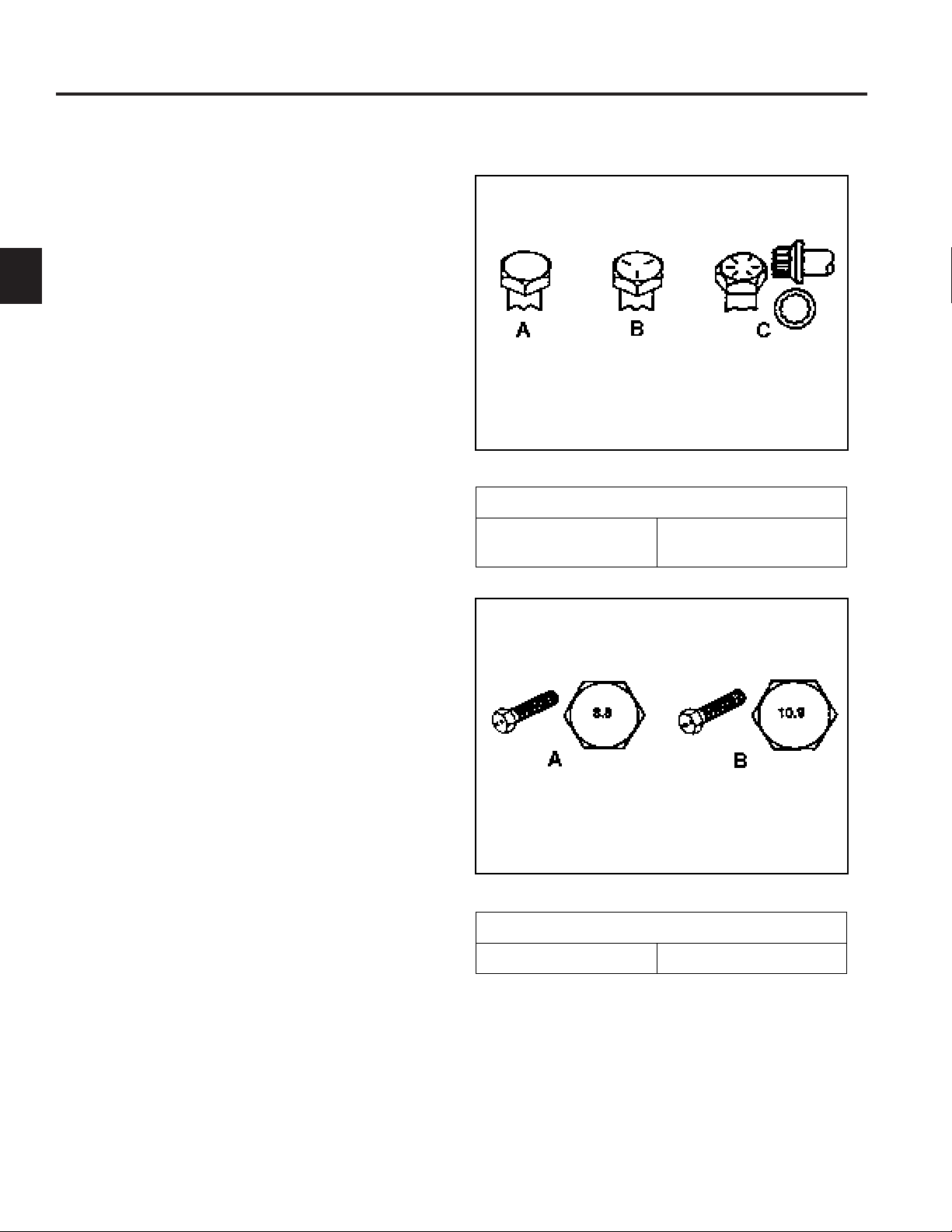
Fastener Identification
Inch Series Bolts and Screws
(A) Grade 1
(B) Grade 5
Figure A
(C) Grade 8
The standard method of verifying torque shall be
performed by marking a line on the fastener (head or
nut) and mating part, then back off fastener 1/4 of a
turn. Measure the torque required to tighten the
fastener until the lines match up.
Figure B
Metric Bolts and Screws
(A) Class 8.8 (B) Class 10.9
2-4 Z580/Z589 DFI Z Master Service Manual
Page 16

SPECIFICATIONS
2
Standard Torque for Dry, Zinc Plated, and Steel Fasteners (Inch Series)
Standard Torque for Dry, Zinc Plated, and Steel Fasteners (Inch Series)
Grade 1, 5, &
Thread Size
# 6 - 32 UNC
# 6 - 40 UNF 17 ± 2 190 ± 20 25 ± 2 280 ± 20
# 8 - 32 UNC
# 8 - 36 UNF 31 ± 3 350 ± 30 43 ± 4 31 ± 3
# 10 - 24 UNC
#10 - 32 UNF 48 ± 4 540 ± 45 68 ± 6 765 ± 70
1/4 - 20 UNC 48 ± 7 53 ± 7 599 ± 79 100 ± 10 1125 ± 100 140 ± 15 1580 ± 170
1/4 - 28 UNF 53 ± 7 65 ± 10 734 ± 113 115 ± 10 1300 ± 100 160 ± 15 1800 ± 170
5/16 - 18 UNC 115 ± 15 105 ± 17 1186 ± 169 200 ± 25 2250 ± 280 300 ± 30 3390 ± 340
5/16 - 24 UNF 138 ± 17 128 ± 17 1446 ± 192 225 ± 25 2540 ± 280 325 ± 30 3670 ± 340
3/8 - 16 UNC 16 ± 2 16 ± 2 22 ± 3 30 ± 3 41 ± 4 43 ± 4 58 ± 5
3/8 - 24 UNF 17 ± 2 18 ± 2 24 ± 3 35 ± 3 47 ± 4 50 ± 4 68 ± 5
7/16 - 14 UNC 27 ± 3 27 ± 3 37 ± 4 50 ± 5 68 ± 7 70 ± 7 68 ± 9
7/16 - 20 UNF 29 ± 3 29 ± 3 39 ± 4 55 ± 5 75 ± 7 77 ± 7 104 ± 9
1/2 - 13 UNC 30 ± 3 48 ± 7 65 ± 9 75 ± 8 102 ± 11 105 ± 10 142 ± 14
1/2 - 20 UNF 32 ± 3 53 ± 7 72 ± 9 85 ± 8 115 ± 11 120 ± 10 163 ± 14
5/8 - 11 UNC 65 ± 10 88 ± 12 119 ± 16 150 ± 15 203 ± 20 210 ± 20 285 ± 27
5/8 - 18 UNF 75 ± 10 95 ± 15 129 ± 20 170 ± 15 230 ± 20 240 ± 20 325 ± 27
3/4 - 10 UNC 93 ± 12 140 ± 20 190 ± 27 265 ± 25 359 ± 34 374 ± 35 508 ± 47
3/4 - 16 UNF 115 ± 15 165 ± 25 224 ± 34 300 ± 25 407 ± 34 420 ± 35 569 ± 47
7/8 - 9 UNC 140 ± 20 225 ± 25 305 ± 34 430 ± 45 583 ± 61 600 ± 60 813 ± 81
7/8 - 14 UNF 155 ± 25 260 ± 30 353 ± 41 475 ± 45 644 ± 61 660 ± 60 895 ± 81
8 with Thin
Height Nuts
In-lb In-lb N-cm In-lb N-cm In-lb N-cm
10 ± 2 13 ± 2 147 ± 23
13 ± 2 25 ± 5 282 ± 30
18 ± 2 30 ± 5 339 ± 56
ft-lb ft-lb N-m ft-lb N-m ft-lb N-m
SAE Grade 1 Bolts, Screws,
Studs, & Sems with Regular
Height Nuts (SAE J995
Grade 2 or Stronger Nuts)
SAE Grade 5 Bolts, Screws,
Studs, & Sems with Regular
Height Nuts (SAE J995
Grade 2 or Stronger Nuts)
15 ± 2 170 ± 20 23 ± 2 260 ± 20
29 ± 3 330 ± 30 41 ± 4 460 ± 45
42 ± 4 475 ± 45 60 ± 6 674 ± 70
SAE Grade 8 Bolts, Screws,
Studs, & Sems with Regular
Height Nuts (SAE J995
Grade 2 or Stronger Nuts)
2
Note: Reduce torque values listed in the table above
by 25% for lubricated fasteners. Lubricated fasteners
are defined as threads coated with a lubricant such as
oil, graphite, or thread sealant such as Loctite.
Note: Torque values may have to be reduced when
installing fasteners into threaded aluminum or brass.
The specific torque value should be determined based
on the fastener size, the aluminum or base material
strength, length of thread engagement, etc.
Note: The nominal torque values listed above for
Grade 5 and 8 fasteners are based on 75% of the
minimum proof load specified in SAE J429. The
tolerance is approximately
value. Thin height nuts include jam nuts.
± 10% of the nominal torque
2-5Z580/Z589 DFI Z Master Service Manual
Page 17

SPECIFICATIONS
Standard Torque for Dry, Zinc, and Steel Fasteners (Metric Fasteners)
Standard Torque for Dry, Zinc, and Steel Fasteners (Metric Fasteners)
2
Class 8.8 Bolts, Screws, and Studs with
Thread Size
M5 X 0.8 57 ± 5 in-lb 640 ± 60 N-cm 78 ± 7 in-lb 885 ± 80 N-cm
M6 X 1.0 96 ± 9 in-lb 1018 ± 100 N-cm 133 ± 13 in-lb 1500 ± 150 N-cm
M8 X 1.25 19 ± 2 ft-lb 26 ± 3 N-m 27 ± 2 ft-lb 36 ± 3 N-m
M10 X 1.5 38 ± 4 ft-lb 52 ± 5 N-m 53 ± 5 ft-lb 72 ± 7 N-m
M12 X 1.75 66 ± 7 ft-lb 90 ± 10 N-m 92 ± 9 ft-lb 125 ± 12 N-m
M16 X 2.0 166 ± 15 ft-lb 225 ± 20 N-m 229 ± 22 ft-lb 310 ± 30 N-m
M20 X 2.5 325 ± 33 ft-lb 440 ± 45 N-m 450 ± 37 ft-lb 610 ± 50 N-m
Note: Reduce torque values listed in the table above
by 25% for lubricated fasteners. Lubricated fasteners
are defined as threads coated with a lubricant such as
oil, graphite, or thread sealant such as Loctite.
Note: Torque values may have to be reduced when
installing fasteners into threaded aluminum or brass.
The specific torque value should be determined based
on the fastener size, the aluminum or base material
strength, length of thread engagement, etc.
Regular Height Nuts
(Class 8 or Strong Nuts)
Note: The nominal torque values listed above are
based on 75% of the minimum proof load specified in
SAE J1199. The tolerance is approximately
the nominal torque value. Thin height nuts include jam nuts.
Class 10.9 Bolts, Screws, and Studs with
Regular Height Nuts (
Class 10 or Strong Nuts)
± 10% of
2-6 Z580/Z589 DFI Z Master Service Manual
Page 18

Other Torque Specications
Other Torque Specifications
SPECIFICATIONS
SAE Grade 8 Steel Set Screws
Recommended Torque
Thread Size
Square Head Hex Socket
1/4 - 20 UNC 140 ± 20 in-lb 73 ± 12 in-lb
5/16 - 18 UNC 215 ± 35 in-lb 145 ± 20 in-lb
3/8 - 16 UNC 35 ± 10 ft-lb 18 ± 3 ft-lb
1/2 - 13 UNC 75 ± 15 ft-lb 50 ± 10 ft-lb
Thread Cutting Screws
(Zinc Plated Steel)
Type 1, Type 23, or Type F
Thread Size Baseline Torque*
No. 6 - 32 UNC 20 ± 5 in-lb
No. 8 - 32 UNC 30 ± 5 in-lb
Wheel Bolts and Lug Nuts
Thread Size Recommended Torque**
7/16 - 20 UNF
Grade 5
1/2 - 20 UNF
Grade 5
M12 X 1.25
Class 8.8
M12 X 1.5
Class 8.8
** For steel wheels and non-lubricated fasteners.
Thread Cutting Screws
Thread
Size
No. 6 18 20 20 ± 5 in-lb
No. 8 15 18 30 ± 5 in-lb
Threads per Inch
Type A Type B
65 ± 10 ft-lb 88 ± 14 N-m
80 ± 10 ft-lb 108 ± 14 N-m
80 ± 10 ft-lb 108 ± 14 N-m
80 ± 10 ft-lb 108 ± 14 N-m
(Zinc Plated Steel)
Baseline Torque*
2
No.10 - 24 UNC 38 ± 7 in-lb
1/4 - 20 UNC 85 ± 15 in-lb
5/16 - 18 UNC 110 ± 20 in-lb
3/8 - 16 UNC 200 ± 100 in-lb
Conversion Factors
in-lb X 11.2985 - N-cm
ft-lb X 1.3558 = N-m
No. 10 12 16 38 ± 7 in-lb
No. 12 11 14 85 ± 15 in-lb
* Hole size, material strength, material thickness and
finish must be considered when determining specific
torque values. All torque values are based on nonlubricated fasteners.
N-cm X - 0.08851 = in-lb
N-cm X 0.73776 - ft-lb
2-7Z580/Z589 DFI Z Master Service Manual
Page 19

2
SPECIFICATIONS
Equivalents and Conversions
Equivalents and Conversions
Decimal and Millimeter Equivalents
Decimal and Millimeter Equivalents
Fractions Decimals mm Fractions Decimals mm
1/64 0.015625 0.397 33/64 0.515625 13.097
1/32 0.03125 0.794 16/32 0.53125 13.484
3/64 0.046875 1.191 35/64 0.546875 13.891
1/16 0.0625 1.588 9/16 0.5625 14.288
5/64 0.078125 1.984 37/64 0.578125 14.684
3/32 0.9375 2.381 19/32 0.59375 15.081
1/8 0.1250 3.175 5/8 0.6250 15.875
9/64 0.140625 3.572 41/64 0.640625 16.272
5/32 0.15625 3.969 21/32 0.65625 16.669
11/64 0.171875 4.366 43/64 0.671875 17.066
3/16 0.1875 4.762 11/16 0.6875 17.462
13/64 0.203125 5.159 45/64 0.703125 17.859
7/32 0.21875 5.556 23/32 0.71875 18.256
15/64 0.234375 5.953 47/64 0.734375 18.653
1/4 0.2500 6.350 3/4 0.7500 19.050
17/64 0.265625 6.747 49/64 0.765625 19.447
9/32 0.28125 7.144 25/32 0.78125 19.844
19/64 0.296875 7.541 51/64 0.796875 20.241
5/16 0.3125 7.541 13/16 0.8125 20.638
21/64 0.328125 8.334 53/64 0.828125 21.034
11/32 0.34375 8.731 27/32 0.84375 21.431
23/64 0.359375 9.128 55/64 0.859375 21.828
3/8 0.3750 9.525 7/8 0.8750 22.225
25/64 0.390625 9.922 57/64 0.890625 22.622
13/32 0.40625 10.319 29/32 0.90625 23.019
27/64 0.421875 10.716 59/64 0.921875 23.416
7/16 0.4375 11.112 15/16 0.9375 23.812
29/64 0.453125 11.509 61/64 0.953125 24.209
15/32 0.46875 11.906 31/32 0.96875 24.606
31/64 0.484375 12.303 63/64 0.984375 25.003
1/2 0.5000 12.700 1 1.000 25.400
1 mm = 0.03937 in. 0.001 in. = 0.0254 mm
2-8 Z580/Z589 DFI Z Master Service Manual
Page 20

Linear
Measurement
Area
Volume
Weight
Pressure
Work
Liquid Volume
Liquid Flows
Temperature
SPECIFICATIONS
U.S. to Metric Conversions
U.S. to Metric Conversions
To Convert Into Multiply By
Miles
Yards
Feet
Feet
Inches
Inches
Inches
Square Miles
Square Feet
Square Inches
Acre
Cubic Yards
Cubic Feet
Cubic Inches
Tons (Short)
Pounds
Ounces
Pounds/Sq. In. Kilopascal
Foot-pounds
Foot-pounds
Inch-pounds
Quarts
Gallons
Gallons/Minute Liters/Minute
Fahrenheit Celsius
Kilometers
Meters
Meters
Centimeters
Meters
Centimeters
Millimeters
Square Kilometers
Square Meters
Square Centimeters
Hectare
Cubic Meters
Cubic Meters
Cubic Centimeters
Metric Tons
Kilograms
Grams
Newton-Meters
Kilogram-Meters
Kilogram-Centimeters
Liters
Liters
1.609
0.9144
0.3048
30.48
0.0254
2.54
25.4
2.59
0.0929
6.452
0.4047
0.7646
0.02832
16.39
0.9078
0.4536
28.3495
6.895
1.356
0.1383
1.152144
0.9463
3.785
3.785
1. Subtract 32°
2. Multiply by 5/9
2
2-9Z580/Z589 DFI Z Master Service Manual
Page 21

2
SPECIFICATIONS
THIS PAGE INTENTIONALLY LEFT BLANK.
2-10 Z580/Z589 DFI Z Master Service Manual
Page 22

CHASSIS
Castor Fork Assembly Replacement
Castor Fork Assembly Removal
1. Raise the front of the machine off the ground leaving
enough clearance to remove the castor fork from the
carrier frame.
2. Remove the grease cap from the frame (Fig. 001).
3. Remove the locknut (Fig. 002).
3
Fig 002 IMG-7874a
4. Slide the castor fork assembly out of the frame (Fig.
003).
Fig 001 IMG-7694a
Fig 003 IMG-7700a
3-1Z580/Z589 DFI Z Master Service Manual
Page 23

CHASSIS
3
Castor Bearing Replacement
1. Remove the 3 Belleville washers (Fig. 004).
Fig 004 IMG-7703a
3. Remove the bottom grease seal (Fig. 006).
Fig 006 IMG-7709a
4. Remove the bottom tapered bearing (Fig. 007).
2. Remove the top tapered bearing (Fig. 005).
Fig 005 IMG-7706a
Fig 007 IMG-7711a
3-2 Z580/Z589 DFI Z Master Service Manual
Page 24
CHASSIS
5. Drive the top and bottom tapered bearing cups out of
the caster fork hub (Fig. 008).
Fig 008 IMG-7714a
6. Install new tapered bearing cups by pressing each
bearing cup into the caster fork hub so that the thick-
er part of the taper is pressed in rst. The bearing
cups should seat against the shoulder inside the
frame.
Section view of caster fork hub (Fig. 009):
7. Pack the upper and lower tapered bearings with
grease (No. 2 general purpose lithium base or
molybdenum grease).
8. Install the lower bearing into the caster fork hub (Fig.
010).
3
Fig 010 IMG-7722a
9. Install the grease seal into the caster fork hub (Fig.
011).
A
B
C
A
Fig 009 tapered bearing cup install
A. Tapered Bearing Cup (2)
B. Caster fork hub (sectioned)
C. Machined shoulder inside caster fork hub (2)
Fig 011 IMG-7725a
3-3Z580/Z589 DFI Z Master Service Manual
Page 25
CHASSIS
3
10. Install the upper bearing into the caster fork hub
(Fig. 012).
Fig 012 IMG-7731a
Castor Fork Assembly Installation
1. Install 3 Bellville washers as shown (Fig. 013):
A
Fig 013 g. 49 G001297
A. Belleville washers
2. Slide the castor fork assembly into the hub (Fig.
014).
Fig 014 IMG-7700a
3-4 Z580/Z589 DFI Z Master Service Manual
Page 26

CHASSIS
3. Install the locknut. Tighten the locknut until the
Belle ville washers are at, then back the nut off 1/4
turn to properly set the preload on the bearings (Fig.
015).
Fig 015 IMG-7874a Fig 017 IMG-7734a
5. Remove the grease tting and install the grease
plug.
6. Install the dust cap onto the frame (Fig. 017).
3
4. Remove the plug located on the side of the castor
hub. Install a grease tting. Apply grease (No.
2 general purpose lithium base or molybdenum
grease) into the hub until it passes through the upper
bear ing. Fill the top cavity with grease (Fig. 016).
Fig 016 PICT-2897a
3-5Z580/Z589 DFI Z Master Service Manual
Page 27

CHASSIS
3
Front Wheel Bearing Replacement
1. Raise the front of the machine off the ground.
2. Remove the wheel axle bolt and nut (Fig. 018).
Fig 018 IMG-7736a
4. Remove the castor spacer from the wheel assembly
(Fig. 020).
Fig 020 IMG-7742a
5. Remove both bearing spacers (one on each side)
from the wheel assembly (Fig. 021).
3. Remove the wheel assembly from the fork (Fig.
019).
Fig 019 IMG-7878a
Fig 021 IMG-7744a
3-6 Z580/Z589 DFI Z Master Service Manual
Page 28

CHASSIS
6. Drive the bearing cup, bearing and bearing seal out
of the wheel assembly. Repeat on the opposite side
(Fig. 022).
Fig 022 IMG-7748a
Wheel Assembly (Fig. 023)
7. Install a new tapered bearing cup into the wheel
assembly by pressing each bearing cup into the
wheel hub so that the thicker part of the taper is
pressed into the wheel hub rst. The bearing cups
should seat against the shoulder divots inside the
wheel hub (Fig. 024).
3
Fig 024 IMG-7881a
E
A AB BC CD D
F
H
Fig 023 IMG-7880a
A. Bearing spacer (2) E. Wheel and tire
B. Grease seal (2) assembly
C. Tapered bearing (2) F. Caster spacer
D. Tapered bearing G. Wheel assembly axle
cup (2) bolt
H. Nut
G
8. Pack both tapered bearings with grease (No. 2 general purpose lithium base or molybdenum grease).
9. Install the tapered bearings into each side of the
wheel hub (Fig. 025).
Fig 025 IMG-7882a
3-7Z580/Z589 DFI Z Master Service Manual
Page 29

CHASSIS
3
10. Install the grease seals into each side of the wheel
hub (Fig. 026).
Fig 026 IMG-7883a
11. Install a bearing spacer into each side of the wheel
hub (Fig. 027).
12. Install the castor spacer into the wheel hub (Fig.
028).
Fig 028 IMG-7885a
13. Position the wheel assembly into the caster fork (Fig.
029).
Fig 027 IMG-7884a
3-8 Z580/Z589 DFI Z Master Service Manual
Fig 029 IMG-7878a
Page 30

CHASSIS
14. Install the axle bolt and nut securing the wheel as-
sembly to the fork (Fig. 030).
Fig 030 IMG-7736a
15. Apply grease (No. 2 general purpose lithium base or
molybdenum grease) to the wheel assembly grease
tting (Fig. 031).
Fuel Tank Replacement
Right Side Fuel Tank Removal
1. Raise the seat and remove the front engine shield
(Fig. 032).
3
Fig 032 IMG-0303a
Fig 031 IMG-7886a
2. Turn the fuel shut-off valve to OFF position (Fig.
033).
Fig 033 IMG-0304a
3-9Z580/Z589 DFI Z Master Service Manual
Page 31

CHASSIS
3
3. Disconnect the negative battery cable.
4. Remove the right rear wheel assembly (Fig. 034).
Fig 034 IMG-0307a
6. Remove the clamp securing the return fuel line to
the tting on the operator’s side of the fuel tank.
Slide the fuel hose off the tting (Fig. 036).
Fig 036 IMG-0309a
5. Remove the clamp securing the fuel line to the tting
on the bottom of the fuel tank. Slide the fuel hose off
the tting and drain the fuel from the tank (Fig. 035).
Fig 035 IMG-0308a
7. Remove the nuts, springs and washers from the 3
studs on the underside of the fuel tank (Fig. 037).
A
B
B
C
C C
Fig 037 RH fuel tank fasteners a
A. Fuel tank C. Mounting stud fastener
B. Frame assembly (3)
3-10 Z580/Z589 DFI Z Master Service Manual
Page 32

CHASSIS
8. Remove the bolt, lockwasher and washer securing
the left front corner of the fuel tank to the frame (Fig.
038).
Fig 038 IMG-0310a
Right Side Fuel Tank Installation
1. Position the fuel tank onto the frame (Fig. 040).
3
Fig 040 IMG-0313a
9. Lift the fuel tank off the frame (Fig. 039).
Fig 039 IMG-0313a
2. Slide a hose clamp onto the return fuel line. Slide
the return fuel line onto the tting located on the
operator’s side of the fuel tank (Fig. 041).
Fig 041 IMG-0317a
3-11Z580/Z589 DFI Z Master Service Manual
Page 33

CHASSIS
3
3. Position the hose clamp and tighten (Fig. 042).
Fig 042 IMG-0320a
4. Slide a hose clamp onto the intake fuel line. Slide
the intake fuel line onto the tting located on the
bottom of the fuel tank. Position the hose clamp and
tighten (Fig. 043).
5. Loosely install a bolt, lock washer, and washer
through the frame and into the front left corner of the
fuel tank (Fig. 044).
Fig 044 IMG-0310a
6. Loosely install a washer, spring and nut onto each
of the three studs on the underside of the fuel tank
(Fig. 045).
Fig 043 IMG-0321a
A
B
B
C
C C
Fig 045 RH fuel tank fasteners a
3-12 Z580/Z589 DFI Z Master Service Manual
Page 34

CHASSIS
7. Tighten the 3 nuts until three threads protrude past
the nut. Do not over-tighten (Fig. 046).
Fig 046 PICT-3290a
8. Tighten the bolt located in the front corner of the
tank to frame (Fig. 047).
9. Install the right rear wheel assembly (Fig. 048).
3
Fig 048 IMG-0307a
10. Install the negative battery cable.
11. Install the front engine shield (Fig. 049).
Fig 047 IMG-0310a
Fig 049 IMG-0303a
3-13Z580/Z589 DFI Z Master Service Manual
Page 35

CHASSIS
3
Left Side Fuel Tank Removal
1. Raise the seat and remove the front engine shield
(Fig. 050).
Fig 050 IMG-0303a
3. Disconnect the negative battery cable.
4. Remove the left rear wheel assembly (Fig. 052).
Fig 052 IMG-0322a
2. Turn the fuel shut-off valve to the “OFF” position
(Fig. 051).
Fig 051 IMG-0304a
5. Remove the 4 screws and washers securing the
control panel to the fuel tank (Fig. 053).
Fig 053 IMG-0327a
3-14 Z580/Z589 DFI Z Master Service Manual
Page 36

CHASSIS
6. Remove the cable tie securing the throttle cable to
the fuel tting (Fig. 054).
Fig 054 IMG-0328a
7. Move the control panel assembly away from the fuel
tank (Fig. 055).
8. Remove the hose clamp from the fuel return line and
tting located on the operator’s side of the fuel tank
(Fig. 056).
3
Fig 056 IMG-0333a
9. Remove the return fuel line from the fuel tting (Fig.
057).
Fig 055 IMG-0331a
Fig 057 IMG-0335a
3-15Z580/Z589 DFI Z Master Service Manual
Page 37

CHASSIS
3
10. Remove the hose clamp from the fuel intake line and
tting located on the underside of the fuel tank (Fig.
058).
Fig 058 IMG-0338a
11. Remove the fuel line from the fuel tting and drain
the fuel from the fuel tank (Fig. 059).
12. Remove the nuts, springs and washers from the 3
fuel tank mounting studs located on the underside of
the fuel tank (Fig. 060).
A
B
C
C
C
Fig 060 LH fuel tank fasteners a
A. Fuel tank C. Mounting stud fastener
B. Frame assembly (3)
Fig 059 IMG-0341a
13. Remove the nut and washer retaining the fuel shutoff valve to the fuel valve bracket (Fig. 061).
Fig 061 IMG-0351a
3-16 Z580/Z589 DFI Z Master Service Manual
Page 38

CHASSIS
14. Remove the bolt and washers securing the right
front corner of the fuel tank to the frame (Fig. 062).
Fig 062 IMG-0350a
15. Remove the fuel tank from the frame (Fig. 063).
Left Side Fuel Tank Installation
1. Position the fuel tank onto the frame (Fig. 064).
3
Fig 064 IMG-0345a
2. Slide a hose clamp onto the return fuel hose. Install
the fuel return hose onto the fuel-tting barb located
on the operator’s side of the fuel tank. Slide the hose
clamp into position and tighten (Fig. 065).
Fig 063 IMG-0345a
Fig 065 IMG-0354a
3-17Z580/Z589 DFI Z Master Service Manual
Page 39

CHASSIS
3
3. Slide the hose clamp onto the fuel intake hose.
Install the fuel intake hose onto the fuel-tting barb
located on the underside of the fuel tank. Slide the
hose clamp into position and tighten (Fig. 066).
Fig 066 IMG-0338a
5. Loosely install a washer, spring and nut onto each
of the three studs on the underside of the fuel tank
(Fig. 068).
A
B
C
C
C
Fig 068 lh fuel tank fasteners
A. Fuel tank C. Mounting stud fastener
B. Frame assembly (3)
4. Install a bolt, lock washer, and washer into the right
front corner of the fuel tank securing it to the frame
(Fig. 067).
Fig 067 IMG-0350a
6. Tighten the nuts until three threads protrude past the
nut. Do not over-tighten (Fig. 069).
Fig 069 PICT-3290
3-18 Z580/Z589 DFI Z Master Service Manual
Page 40

CHASSIS
7. Install the fuel shut-off valve to the fuel valve bracket
with a washer and nut (Fig. 070).
Fig 070 IMG-0351a
8. Install 4 screws and washers securing the control
panel to the fuel tank (Fig. 071).
9. Install a cable tie securing the throttle cable to the
fuel tank tting located on the operator’s side of the
fuel tank (Fig. 072).
3
Fig 072 IMG-0416a
10. Install the left rear tire assembly and lower the
machine to the ground.
Fig 071 IMG-0327a
11. Install the negative battery cable.
12. Install the front engine shroud (Fig. 073).
Fig 073 IMG-0303a
13. Lower the seat.
3-19Z580/Z589 DFI Z Master Service Manual
Page 41

CHASSIS
3
Fuel Tank Fitting Replacement
There are 2 fuel ttings located on each of the fuel tanks.
The following procedure can be used to replace any of
the ttings (Fig. 074).
Fig 074 IMG-7771a
2. Using a magnet tool, remove the tting from the
inside of the fuel tank (Fig. 076).
Fig 076 IMG-7774a
3. Using a magnet tool, install a fuel tank tting by
inserting it through the fuel tank opening (Fig. 077).
1. Remove the nut and washer securing the tting to
the fuel tank (Fig. 075).
Fig 075 IMG-7772a
Fig 077 IMG-7775a
3-20 Z580/Z589 DFI Z Master Service Manual
Page 42

CHASSIS
4. Loosely install a washer and nut to secure the fuel
tank tting to the fuel tank (Fig. 078).
Fig 078 IMG-7772a
5. Position the fuel tank ttings as shown (Fig. 079, Fig.
080 and Fig. 081):
Right side fuel tank operator’s side tting
3
Fig 080 DSC-4856a
Left side fuel tank operator’s side tting
Right and left fuel tank bottom tting
Fig 079 IMG-7781a
Fig 081 DSC-4854a
6. Tighten the tting nut.
3-21Z580/Z589 DFI Z Master Service Manual
Page 43

CHASSIS
3
Hood Assembly Replacement
Hood Assembly Removal
1. Unhook the rubber latch that is located on the rear of
the hood (Fig. 082).
Fig 082 IMG-0361a
3. Lift the hood and remove from the machine (Fig.
084).
Fig 084 IMG-0369a
2. Remove the two hairpin cotters, clevis pins, and
washers in the left and right hinges (Fig. 083).
Fig 083 IMG-0365a
3-22 Z580/Z589 DFI Z Master Service Manual
Page 44

CHASSIS
Hood Assembly Installation
1. Align the hood pivot brackets with holes in the pivot
bracket on the frame (Fig. 085).
Fig 085 IMG-0370a
2. Install a clevis pin, washer and hairpin cotter into
each of the pivot brackets (Fig. 086).
Note: The hood screen can contact the radiator cap.
The pressure on the cap can result in a crack
at the cap adapter joint, resulting in loss of
radiator pressure and overheating.
Check the clearance between the hood screen
and the radiator cap. If there is any interfer
ence, the hood can be adjusted using the
slotted holes in the hood mounting brackets.
3
Fig 086 IMG-0365a
3-23Z580/Z589 DFI Z Master Service Manual
Page 45

CHASSIS
3
Hood hinge plate adjustment slots (Fig. 087).
Fig 087 IMG-0381a
Hood pivot plate adjustment slots (Fig. 088).
3. Lower the hood and hook the rubber latch located at
the rear of the hood (Fig. 089).
Fig 089 IMG-0361a
Fig 088 IMG-0382a
3-24 Z580/Z589 DFI Z Master Service Manual
Page 46

CHASSIS
Throttle Control Assembly Replacement
Throttle Control Assembly Removal
1. Raise the seat.
2. Disconnect the negative battery cable from the
battery terminal.
3. Remove the knob from the throttle control assembly
(Fig. 090).
4. Remove the 4 screws securing the control panel to
the left hand fuel tank (Fig. 091).
3
Fig 091 IMG-0385a
5. Remove the locknuts and carriage bolts securing the
throttle control to the control panel (Fig. 092).
Fig 090 IMG-0383a
Fig 092 IMG-0386a
3-25Z580/Z589 DFI Z Master Service Manual
Page 47

CHASSIS
3
6. Remove the front engine panel shield assembly (Fig.
093).
Fig 093 IMG-0303a
7. Remove the cable tie securing the throttle cable to
the fuel tank tting (Fig. 094).
8. Remove the cable tie securing the throttle cable to
the bracket located behind the voltage regulator (Fig.
095).
Fig 095 IMG-0387a
9. Loosen the cable clamp and remove the throttle
cable (Fig. 096).
Fig 094 IMG-0328a
Fig 096 IMG-0388a
3-26 Z580/Z589 DFI Z Master Service Manual
Page 48

CHASSIS
10. Remove the z-bend end of the cable from the throttle
arm assembly (Fig. 097).
Fig 097 IMG-0390a
11. Remove the throttle cable from the unit.
Throttle Control Assembly Installation
1. Slide the throttle cable through the slot in the side of
the control panel (Fig. 098).
3
Fig 098 IMG-0392a
2. Install the throttle cable assembly into the slot in the
control panel (Fig. 099).
Fig 099 IMG-0393a
3-27Z580/Z589 DFI Z Master Service Manual
Page 49

CHASSIS
3
3. Install the carriage bolts and locknuts securing the
throttle control assembly to the control panel (Fig.
100).
Fig 100 IMG-0386a
4. Route the throttle cable behind the fuel tank tting
(Fig. 101).
5. Route the throttle cable behind the engine breather
tube (Fig. 102).
Fig 102 IMG-0397a
6. Then route the cable back on the right side of the
engine to the throttle linkage (Fig. 103).
Fig 103 IMG-0405a
Fig 101 IMG-0396a
3-28 Z580/Z589 DFI Z Master Service Manual
Page 50

CHASSIS
7. Insert the z-bend of the throttle cable into the throttle
arm assembly (Fig. 104).
Fig 104 IMG-0406a
8. Install the throttle cable into the cable clamp on the
engine throttle linkage (Fig. 105).
9. Install the 4 screws securing the control panel to the
left hand fuel tank. Install the knob for the throttle
control assembly. Move the throttle control to the low
idle speed setting (Fig. 106).
3
Fig 106 IMG-0408a
10. Adjust the throttle linkage on the engine. Lightly
push the cable toward the Z-bend end of the cable
and tighten the cable clamp (Fig. 107).
Fig 105 IMG-0407a
Fig 107 IMG-0410a
3-29Z580/Z589 DFI Z Master Service Manual
Page 51

CHASSIS
3
11. Install a cable tie securing the throttle cable to the
bracket located behind the voltage regulator (Fig.
108).
Fig 108 IMG-0414a
12. Install a cable tie securing the throttle cable to the
fuel tank tting located on the operator’s side of the
fuel tank (Fig. 109).
13. Install the front engine shield assembly (Fig. 110).
Fig 110 IMG-0303a
14. Connect the negative battery cable.
15. Start the unit and operate the throttle control, to
check for proper function and adjustment.
Fig 109 IMG-0416a
3-30 Z580/Z589 DFI Z Master Service Manual
Page 52

CHASSIS
Brake Lever Replacement
The left fuel tank and hood have been removed for photo
purposes.
Brake Lever Removal
1. Raise the seat.
2. Disconnect the negative battery cable from the
battery terminal.
3. Lower the seat.
4. Release the parking brake (forward position).
5. Remove the cotter pin and clevis pin securing the
brake linkage yoke to the brake lever assembly (Fig.
111).
6. Lift the oor pan assembly.
7. Remove the brake lever pivot shaft cotter pin (Fig.
112).
3
Fig 112 IMG-7922a
Fig 111 PICT-2915a
8. Slide the brake lever out of the pivot bushings (Fig.
113).
Fig 113 PICT-2913a
3-31Z580/Z589 DFI Z Master Service Manual
Page 53

3
CHASSIS
9. With a hammer and punch tap out the two pivot
bushings (Fig. 114).
Fig 114 PICT-2883a
10. Inspect the brake shaft and bushings for excessive
wear. Replace any worn or damaged components
(Fig. 115).
Fig 115 PICT-2887a
3-32 Z580/Z589 DFI Z Master Service Manual
Page 54

CHASSIS
Brake Lever Installation
1. Raise the oor pan assembly.
2. Install the two bushings into the brake lever pivot
mounting hole (Fig. 116).
Fig 116 PICT-2891a
4. Install a cotter pin into the pivot shaft (Fig. 118).
3
Fig 118 IMG-7922a
5. Lower the oor pan assembly.
6. Move the parking brake lever into the released
(forward) position.
3. Slide the brake lever assembly pivot through the
bushings (Fig. 117).
Fig 117 PICT-2892a
7. Position the brake linkage yoke to the brake lever.
Install a clevis and cotter pin to secure (Fig. 119).
Fig 119 PICT-2895a
3-33Z580/Z589 DFI Z Master Service Manual
Page 55

CHASSIS
3
Brake Band Replacement
Note: The following procedures can be followed for
both right and left brake band removal and
installation.
Brake Band Removal
1. Remove the rear tire (Fig. 120).
2. Remove the 3 bolts, spacer and retainer from the
brake band assembly (Fig. 121).
Fig 121 PICT-2920a
3. Remove the 2 spacers from the brake band (Fig.
122).
Fig 120 PICT-2919a
Fig 122 PICT-2935a
3-34 Z580/Z589 DFI Z Master Service Manual
Page 56

CHASSIS
4. Remove the brake band from the wheel and hub
assembly (Fig. 123).
Fig 123 PICT-2933a
5. Inspect the brake band. Replace if worn or
damaged.
Brake Band Assembly (Fig. 124)
Brake Band Installation
1. Slide the brake band onto the wheel hub assembly
(Fig. 125).
3
Fig 125 PICT-2933a
2. Slide a spacer into each end of the brake band (Fig.
126).
A
B
C
D
Fig 124 PICT-2926a
A. Shoulder bolt (3) C. Retainer
B. Spacer (3) D. Brake band
Fig 126 PICT-2935a
3-35Z580/Z589 DFI Z Master Service Manual
Page 57

CHASSIS
3
3. Position the brake band retainer and loosely install 2
bolts through the retainer, brake band spacers and
into the brake bracket (Fig. 127).
Fig 127 PICT-2941a
4. Position the third spacer between the retainer and
the brake bracket. Loosely install the third bolt
through the retainer and spacer and into the brake
bracket (Fig. 128).
5. Tighten the 3 brake band retainer bolts (Fig. 129).
Fig 129 PICT-2942a
6. Install the rear tire (Fig. 130).
Fig 130 PICT-2919a
7. Check operation/adjustment of the parking brake.
Fig 128 PICT-2936a
3-36 Z580/Z589 DFI Z Master Service Manual
See “Adjusting the Parking Brake” on page 3-65.
Page 58

CHASSIS
Brake Cross Shaft Replacement
Note: The front engine shield has been removed for
photo purposes.
Brake Cross Shaft Removal
1. Raise the seat.
2. Remove the negative battery cable from the battery.
3. Raise the rear tires off the ground and remove the
left and right tires (Fig. 131).
Note: To prevent the unit from rolling, block the
front tires.
4. Remove the two clevis spring pins securing the
brake rod linkage yokes to the left side of the brake
cross shaft (Fig. 132).
3
Fig 132 PICT-2954a
Fig 131 PICT-2919a
5. Remove the clevis spring pin securing the brake rod
linkage yoke to the right side of the brake cross shaft
(Fig. 133).
Fig 133 PICT-2956a
3-37Z580/Z589 DFI Z Master Service Manual
Page 59

CHASSIS
3
6. Remove the 2 bolts and nuts securing the right side
ange bearing to the frame. Remove the ange
bearing from the cross shaft (Fig. 134).
Fig 134 PICT-2958a
7. Remove the 2 bolts and nuts securing the left side
ange bearing to the frame. Remove the ange
bearing from the cross shaft (Fig. 135).
8. Remove brake cross shaft (Fig. 136).
Fig 136 PICT-2964a
9. Inspect brake cross shaft and bearings. Replace if
worn or damaged (Fig. 137).
B B
Fig 135 PICT-2960a
D
C C
A A
Fig 137 PICT-2968a
A. Bolt (4) C. Nuts (4)
B. Side ange bearing (2) D. Brake cross shaft
3-38 Z580/Z589 DFI Z Master Service Manual
Page 60

CHASSIS
Brake Cross Shaft Installation
1. Slide the brake cross shaft into position (Fig. 138).
Note: The end of the cross shaft with two tabs is
installed on the left side of the machine.
Fig 138 PICT-2964a
2. Position a ange bearing onto each end of the cross
shaft with the ange facing outward (Fig. 139).
3. Position the ange bearing on the right end of the
cross shaft and install 2 bolts and nuts securing the
ange bearing to the frame (Fig. 140).
3
Fig 140 PICT-2958a
4. Position the ange bearing to the left side of the
frame and install 2 bolts and nuts to secure the
ange bearing to the frame (Fig. 141).
Fig 139 PICT-2970a
Fig 141 PICT-2960a
3-39Z580/Z589 DFI Z Master Service Manual
Page 61

CHASSIS
3
5. Ensure the brake cross shaft rotates freely in the
ange bearings.
6. Install the clevis spring pin securing the brake rod
linkage yoke to the right side of the brake cross shaft
(Fig. 142).
Fig 142 PICT-2956a
8. Install the left and right rear tires and lower the
machine to the ground (Fig. 144).
Fig 144 PICT-2919a
9. Lower the seat.
7. Install the two clevis spring pins securing the brake
rod linkage yokes to the left side of the brake cross
shaft (Fig. 143).
Fig 143 PICT-2954a
10. Adjust the parking brake. Refer to “Adjusting the
Parking Brake” on page 3-65.
3-40 Z580/Z589 DFI Z Master Service Manual
Page 62

CHASSIS
Deck Lift Lever Replacement
Deck Lift Lever Removal
1. Park the machine on a level surface, disengage the
PTO, turn the ignition off and remove the key.
2. Raise the seat.
3. Remove the negative battery cable from the battery.
4. Place the mower deck in the transport position.
Position wood blocks under each corner of the
mower deck (Fig. 145).
5. Lower the mower deck onto the blocks to remove
tension from the deck lift chains (Fig. 146).
3
Fig 146 PICT-2973a
6. Remove the lower stop bolt from the deck lift plate
(Fig. 147).
Fig 145 PICT-2971a
Fig 147 PICT-2978a
3-41Z580/Z589 DFI Z Master Service Manual
Page 63

CHASSIS
3
7. Loosen the jam nut and hex nut on the right hand
and left hand deck lift rods until the deck support
springs are fully extended (Fig. 148).
Fig 148 PICT-2980a
9. Lower the deck lift lever to its lowest position. The
rear deck swivel mounts should clear the deck lift
rods on both sides. The mower deck lift linkage
should now be fully unloaded (Fig. 150).
Fig 150 PICT-2984a
8. Remove the hex nut from the back end of the right
and left deck lift assemblies (Fig. 149).
Fig 149 PICT-2982a
10. Remove the bolt, nut and lift lever bushing that
secures the inner deck lift plate to the frame (Fig.
151).
Fig 151 PICT-2987a
3-42 Z580/Z589 DFI Z Master Service Manual
Page 64

CHASSIS
11. Remove the outside hex head ange nut at the top
of the inner deck lift plate. Remove the hitch pin
assembly from the bolt (Fig. 152).
Fig 152 PICT-2988a
13. Raise the oor pan.
14. Remove the front bolt and nut that secure the 2
deck lift arms to the deck lift cross shaft assembly.
Pivot the deck lift arms away from the cross shaft
assembly and remove the bushing from the hole in
the cross shaft assembly tab (Fig. 154).
3
12. Loosen the inner hex head ange nut. Pivot the
inner deck lift plate up (Fig. 153).
Fig 153 PICT-2991a
Fig 154 PICT-3000a
15. Remove the E-clip from the deck lift arm pivot (Fig.
155).
Fig 155 PICT-3002a
3-43Z580/Z589 DFI Z Master Service Manual
Page 65

CHASSIS
3
16. Remove the deck lift lever assembly from the pivot
(Fig. 156).
Fig 156 PICT-3014a
Note: There may be interference between the lift
lever assembly and the oor pan hinge when
trying to remove the lift lever assembly (Fig.
157).
17. If there is interference between the lift lever assembly and the oor pan hinge, loosen the right hand
oor pan hinge mounting hardware, push the hinge
upward and re-tighten the oor pan hinge mounting
hardware (Fig. 158).
Fig 158 PICT-3008a
Deck Lift Lever Assembly (Fig. 159)
Fig 157 PICT-3005a
A
E
B
C
D
Fig 159 PICT-3015a
A. Bolt D. Nut
B. Bushing E. Lift Lever Assembly
C. Deck lift arm (2)
3-44 Z580/Z589 DFI Z Master Service Manual
Page 66

CHASSIS
Deck Lift Lever Installation
1. Slide the deck lift lever assembly pivot into the pivot
mount on the frame (Fig. 160).
Fig 160 PICT-3011a
2. Install an E-clip onto the deck lift lever pivot (Fig.
161).
3. Slide the bushing into the hole in the cross shaft
assembly tab (Fig. 162).
3
Fig 162 PICT-3019a
4. Rotate the deck lift arms forward to align them with
the bushing in the cross shaft assembly tab. Install a
bolt and nut to secure (Fig. 163).
Fig 161 PICT-3018a
Fig 163 PICT-3000a
3-45Z580/Z589 DFI Z Master Service Manual
Page 67

CHASSIS
3
5. Rotate the inner deck lift plate down to the mounting
hole in the frame. Position a spacer in between
the inner and outer plates. Install a bolt and nut to
secure (Fig. 164).
Fig 164 PICT-3022a
6. Lower the oor pan assembly.
8. Slide the hitch pin lanyard onto the bolt (Fig. 166).
Fig 166 PICT-3027a
9. Install a second nut onto the bolt securing the hitch
pin lanyard in place; do not tighten nut against the
lanyard (Fig. 167).
7. Tighten the nut on the bolt at the top of the inner
deck lift plate (Fig. 165).
Fig 165 PICT-3023a
Fig 167 PICT-3028a
3-46 Z580/Z589 DFI Z Master Service Manual
Page 68

CHASSIS
10. Lift up on the lift lever and install the lower stop bolt
into the deck lift plate (Fig. 168).
Fig 168 PICT-2978a
11. Lower the lift lever. The deck lift lever rods should
run through the rear swivels (Fig. 169).
12. Install a hex nut onto the back end of the right and
left deck lift assemblies (Fig. 170).
3
Fig 170 PICT-2982a
13. Raise the mower deck to the transport position.
Remove the wood blocks. Tighten the adjusting
nut on the deck lift assemblies so that the following
length is achieved between the two large washers
(Fig. 171):
Fig 169 PICT-3029a
A. 52” Mower Deck: 11.0” + .25” (27.9 + .6cm)
B. 60” Mower Deck: 10.5” + .25” (26.7 + .6cm)
C. 72” Mower Deck: 11.5” + .25” (29.2 + .6cm)
Fig 171 PICT-3034a
3-47Z580/Z589 DFI Z Master Service Manual
Page 69

CHASSIS
3
14. Check the deck level adjustment. Refer to “Leveling
the Mower” on page 7-79.
15. Apply grease to the grease tting on the deck lift
lever pivot (Fig. 172).
Fig 172 PICT-3035a
Motion Control Assembly Replacement
Motion Control Assembly Removal
1. Park the machine on a level surface, disengage the
PTO, turn the ignition off and remove the key.
2. Raise the seat.
3. Remove the negative battery cable from the battery.
4. Remove both oor pan assembly hinge bolts and
nuts (Fig. 173).
16. Install the negative battery cable from the battery.
17. Lower the seat.
Fig 173 PICT-3052a
3-48 Z580/Z589 DFI Z Master Service Manual
Page 70

CHASSIS
5. Remove the oor pan assembly (Fig. 174).
Fig 174 PICT-3053a
6. Remove the 2 top pocket mounting bolts, washers
and nuts and the 2 bottom pocket mounting bolts
and nuts (Fig. 175).
7. Remove the pocket (Fig. 176).
3
Fig 176 PICT-3057a
Note: Raise the seat to remove the top two bolts
and nuts.
A
B
Fig 175 PICT-3055a
A. Bolt, washer, nut B. Bolt, nut
A
B
3-49Z580/Z589 DFI Z Master Service Manual
Page 71

CHASSIS
3
Right Hand Motion Control Assembly Removal
8. Remove the 2 bolts and washers securing the right
lever to the control shaft arm. Remove the right lever
(Fig. 177).
Fig 177 PICT-3064a
10. Disconnect the harness from the neutral switch
located under the right side of the traction frame
assembly (Fig. 179).
Fig 179 PICT-3075a
11. Remove the bolt, washer and nut that secure the
right hand control rod assembly to the right hand
motion control assembly (Fig. 180).
9. Remove the outside nut from the bolt that secures
the motion control damper to the right hand motion
control assembly (Fig. 178).
Fig 178 PICT-3066a
Fig 180 PICT-3079a
3-50 Z580/Z589 DFI Z Master Service Manual
Page 72

CHASSIS
12. Remove the cotter pin and clevis pin that secure the
neutral return yoke to the right hand motion control
assembly (Fig. 181).
Fig 181 PICT-3081a
14. Remove the 2 bolts and nuts securing the side
ange bearing to the inside of the traction frame
(Fig. 183).
3
Fig 183 PICT-3084a
13. Loosen the jam nut on the right hand neutral return
spring assembly. Remove the yoke from the neutral
return bolt (Fig. 182).
Fig 182 PICT-3087a
15. Remove the 2 bolts and nuts securing the side
ange bearing to the left hand motion control
assembly (Fig. 184).
Fig 184 PICT-3086a
3-51Z580/Z589 DFI Z Master Service Manual
Page 73

CHASSIS
3
16. Remove the right hand motion control assembly and
right hand control shaft arm assembly (Fig. 185).
Fig 185 PICT-3088a
17. Inspect the side ange bearings. Replace if worn or
damaged (Fig. 186).
Left Hand Motion Control Assembly Removal
18. Remove the 2 bolts, and washers securing the left
lever to the control shaft arm. Remove the left lever
(Fig. 187).
Fig 187 PICT-3098a
B
C
A
D
Fig 186 PICT-3091a
A. Side ange bearing (2)
B. Control shaft arm
C. Right hand motion control assembly
D. Neutral switch
A
19. Raise the seat and remove the outside nut from the
bolt that secures the motion control damper to the
left hand motion control assembly (Fig. 188).
Fig 188 PICT-3102a
3-52 Z580/Z589 DFI Z Master Service Manual
Page 74

CHASSIS
20. Disconnect the harness from the neutral switch
located under the traction frame assembly.
Note: Access the switch from under the seat area.
21. Remove the bolt, washer and nut that secure the left
hand control rod assembly to the left hand motion
control assembly (Fig. 189).
23. Loosen the left hand neutral return assembly jam
nut. Remove the yoke from the neutral return bolt
(Fig. 191).
3
Fig 191 PICT-3126a
Fig 189 PICT-3109a
22. Remove the cotter pin and clevis pin that secure the
neutral return yoke to the left hand motion control
assembly (Fig. 190).
24. Remove the nut, bolt and washer securing the left
hand control rod ball joint to the hydrostatic pump
control arm (Fig. 192).
Fig 192 PICT-3131a
Fig 190 PICT-3124a
3-53Z580/Z589 DFI Z Master Service Manual
Page 75

CHASSIS
3
25. Remove the left hand control rod assembly (Fig.
193).
Fig 193 PICT-3133a
26. Remove the 2 bolts and nuts securing the side
ange bearing to the inside of the traction frame
(Fig. 194).
27. Remove the left hand motion control assembly and
left hand control shaft arm assembly (Fig. 195).
Fig 195 PICT-3135a
28. Inspect the side ange bearings. Replace if worn or
damaged (Fig. 196).
Fig 194 PICT-3128a
D
A
C
A
B
Fig 196 PICT-3137a
A. Side ange bearing (2)
B. Left hand motion control assembly
C. Neutral switch (on reverse side)
D. Control shaft arm
3-54 Z580/Z589 DFI Z Master Service Manual
Page 76

CHASSIS
Left Hand Motion Control Assembly Installation
1. Slide a side ange bearing onto each end of the left
hand motion control assembly (Fig. 197).
Fig 197 PICT-3138a
3. Install 2 bolts and nuts securing the side ange
bearing to the inside of the traction frame (Fig. 199).
3
Fig 199 PICT-3128a
4. Position the left hand control rod assembly into the
traction frame (Fig. 200).
2. Position the left hand motion control assembly and
control shaft arm assembly into the traction frame
(Fig. 198).
Fig 198 PICT-3134a
Fig 200 PICT-3133a
3-55Z580/Z589 DFI Z Master Service Manual
Page 77

CHASSIS
3
5. Install a bolt, washer and nut securing the left hand
control rod ball joint to the hydrostatic pump control
arm (Fig. 201).
Note: The washer is installed between the ball joint
and the control arm.
Fig 201 PICT-3131a
7. Position the left hand neutral return yoke to the left
hand motion control tab and install a clevis pin and
cotter pin (Fig. 203).
Fig 203 PICT-3124a
8. Tighten the jam nut to secure the neutral adjustment
yoke (Fig. 204).
6. Install the neutral return yoke onto the neutral return
bolt (Fig. 202).
Fig 202 PICT-3126a
Note: The neutral return spring may need adjust
ment after the motion contol levers are instal
led. The motion control lever, when moved to
reverse position, should spring back to the
neutral postions when the handles are let go.
Fig 204 PICT-3142a
3-56 Z580/Z589 DFI Z Master Service Manual
Page 78

CHASSIS
Right Hand Motion Control Assembly Installation
9. Slide a side ange bearing onto each end of the right
motion control assembly (Fig. 205).
Fig 205 PICT-3092a
11. Position the side ange bearing to the left hand
motion control assembly and loosely install 2 bolts
and nuts to secure the side ange bearing (Fig.
207).
3
Fig 207 PICT-3144a
10. Position the right hand motion control assembly and
control shaft arm assembly into position under the
traction frame (Fig. 206).
Fig 206 PICT-3088a
12. Position the side ange bearing to the inside of the
traction control frame and loosely install 2 bolts and
nuts securing the side ange bearing (Fig. 208).
Fig 208 PICT-3084a
3-57Z580/Z589 DFI Z Master Service Manual
Page 79

CHASSIS
3
13. Thread the yoke onto the neutral return bolt (Fig.
209).
Fig 209 PICT-3145a
14. Position the neutral return yoke to the right hand
motion control tab and install a clevis pin. Install a
cotter pin into the clevis pin to secure (Fig. 210).
15. Tighten the jam nut to secure the yoke (Fig. 211).
Note: The neutral return spring may need adjust
ment after the motion contol levers are instal
led. The motion control lever, when moved to
reverse position, should spring back to the
neutral postions when the handles are let go.
Fig 211 PICT-3149a
Fig 210 PICT-3081a
16. Install the bolt, washer and nut securing the right
hand control rod assembly to the right hand motion
control assembly (Fig. 212).
Note: The washer is installed between the ball joint
and motion control assembly tab.
Fig 212 PICT-3151a
3-58 Z580/Z589 DFI Z Master Service Manual
Page 80

CHASSIS
17. Install a bolt, washer and nut securing the left hand
control rod assembly to the left hand motion control
assembly (Fig. 213).
Note: The washer is installed between the ball joint
and motion control assembly tab.
Fig 213 PICT-3109a
19. Connect the harness to the 2 neutral switches
located under the seat, behind the left hand and right
and sides of the traction control frame under the
traction frame assembly.
Right hand neutral switch (Fig. 215)
3
Fig 215 PICT-3075a
18. Raise the seat and insert the right and left damper
bolts into the right and left motion control assembly
tabs. Install a nut onto each of the damper bolts to
secure the motion control dampers to the motion
control assemblies (Fig. 214).
Fig 214 PICT-3156a
Left hand neutral switch - access by raising seat (Fig.
216)
A
Fig 216 PICT-4221a
A. Left hand neutral switch located under the traction
frame front console.
3-59Z580/Z589 DFI Z Master Service Manual
Page 81

CHASSIS
3
20. Tighten all 6 bolts and nuts securing the 4 side
ange bearings:
A. Flange bearing mounted to the inside (right) of the
traction control frame (Fig. 217).
Fig 217 PICT-3084a
B. Flange bearings mounted to the left hand motion
control assembly (Fig. 218).
C. Flange bearing mounted to the inside (left) of the
traction frame (Fig. 219).
Fig 219 PICT-3161a
21. Position the left hand control lever to the left hand
control shaft arm. Install 2 bolts, and washers
securing the left lever to the control shaft arm (Fig.
220).
Fig 220 PICT-3098a
Fig 218 PICT-3086a
3-60 Z580/Z589 DFI Z Master Service Manual
Page 82

CHASSIS
22. Position the right hand control lever to the right
hand control shaft arm. Install 2 bolts, and washers
securing the right hand lever to the control shaft arm
(Fig. 221).
Fig 221 PICT-3064a
Motion Control Assembly Installation
25. Insert the pocket into the traction frame (Fig. 222).
3
Fig 222 PICT-3057a
23. Adjust the control handle neutral position. Refer to
“Adjusting the Control Handle Neutral Position” on
page 4-27.
24. Adjust the hydrostatic pump neutral. Refer to “Setting the Hydrostatic Pump Neutral” on page 4-28.
26. Install 2 top pocket mounting bolts, washers and
nuts and 2 bottom pocket mounting bolts and nuts
(Fig. 223).
Note: Raise the seat to install the top 2 bolts,
washers and nuts.
A
B
Fig 223 PICT-3055a
A
B
A. Bolt, washer, nut B. Bolt, nut
3-61Z580/Z589 DFI Z Master Service Manual
Page 83

CHASSIS
3
27. Position the oor pan assembly (Fig. 224).
Fig 224 PICT-3053a
28. Install both oor pan assembly hinge bolts and nuts
(Fig. 225).
Motion Control Damper Replacment
There is a right and a left motion control damper. The
following removal and installation procedures are done
on the right damper. The procedure is the same for the
left damper.
Motion Control Damper Removal
1. Park the machine on a level surface, disengage the
PTO, turn the ignition off and remove the key.
2. Raise the seat.
3. Remove the negative battery cable from the battery.
4. Remove the outer nut from the bolt on the lower end
of the damper (Fig. 226).
Fig 226 PICT-3171a
Fig 225 PICT-3052a
29. Install the negative battery cable from the battery.
30. Lower the seat.
3-62 Z580/Z589 DFI Z Master Service Manual
Page 84

CHASSIS
5. Remove the outer nut from the bolt on the upper end
of the damper (Fig. 227).
Fig 227 PICT-3173a
6. Remove the damper assembly (Fig. 228).
Damper Assembly (Fig. 229)
3
Fig 229 PICT-3181a
Fig 228 PICT-3178a
3-63Z580/Z589 DFI Z Master Service Manual
Page 85

CHASSIS
3
Motion Control Damper Installation
1. Raise the seat.
2. Position the damper assembly with the rod end
down (Fig. 230).
Fig 230 PICT-3178a
4. Insert the lower damper bolt into the frame and
install a nut to secure the lower end of the damper
(Fig. 232).
Fig 232 PICT-3171
5. Install the negative battery cable to the battery.
3. Insert the upper damper bolt into the motion control
assembly arm. Install a nut to secure the upper end
of the damper (Fig. 231).
Fig 231 PICT-3173a
6. Lower the seat.
3-64 Z580/Z589 DFI Z Master Service Manual
Page 86

Adjusting the Parking Brake
1. Engage the parking brake, (lever up).
2. Measure the length of the spring. Measurement
should be 2-1/2” (64mm) between the washers (Fig.
233).
A
CHASSIS
3
C
Fig 233 g. 57 G001294
A. Brake lever in B. Spring 2-1/2” (64mm)
engaged position C. Adjusting nut & jam nut
3. If adjustment is necessary, release the parking
brake, loosen the jam nut below the spring and adjust the nut directly below the spring (Fig. 233). Turn
the nut until the correct measurement is obtained.
Turn the nut clockwise to shorten spring length and
turn counterclockwise to lengthen the spring.
4. Tighten the two nuts together.
5. Engage the parking brake, lever up. Check the
measurement of the spring again.
6. If adjustment is necessary, repeat the procedures
above.
7. Repeat on the opposite side of machine.
B
3-65Z580/Z589 DFI Z Master Service Manual
Page 87

3
CHASSIS
THIS PAGE INTENTIONALLY LEFT BLANK.
3-66 Z580/Z589 DFI Z Master Service Manual
Page 88

HYDRAULIC SYSTEM
Hydrostatic Tandem Pump Replacement
Note: Cleanliness is a key factor in a successful
repair of any hydrostatic system. Thoroughly
clean all exposed surfaces prior to any type of
maintenance. Cleaning all parts with a solvent
wash and air drying is usually adequate.
As with any precision equipment, all parts
must be kept free of foreign material and
chemicals. Protect all exposed sealing areas
and open cavities from damage and foreign
material.
Upon removal, all seals, o-rings, and gaskets
should be replaced. Lightly lubricate all seals,
o-rings and gaskets with clean petroleum jelly
prior to installation.
Hydrostatic Tandem Pump Removal
1. Park the machine on a level surface, disengage the
PTO, set the parking brake, turn the ignition off and
remove the key.
5. Remove the pump idler arm spring using a spring
tool (Toro p/n: 92-5771) (Fig. 235).
Fig 235 IMG-0595a
6. Remove the belt from the pump pulley (Fig. 236).
4
2. Raise the seat.
3. Remove the negative battery cable from the battery.
4. Remove the front engine shield (Fig. 234).
Fig 234 IMG-0303a
Fig 236 IMG-0431a
4-1Z580/Z589 DFI Z Master Service Manual
Page 89

HYDRAULIC SYSTEM
7. Remove the 2 pump pulley set screws (Fig. 237). 9. Remove the key from the keyway (Fig. 239).
4
Fig 237 IMG-0433a
8. Remove the pump pulley (Fig. 238).
Fig 238 IMG-0434a
Fig 239 IMG-0439a
10. Remove the bolt, nut and washer securing the right
hand control rod assembly to the pump control arm
(Fig. 240).
Fig 240 PICT-3195a
4-2 Z580/Z589 DFI Z Master Service Manual
Page 90

HYDRAULIC SYSTEM
11. Remove the bolt, nut and washer securing the left
hand control rod assembly to the pump control arm
(Fig. 241).
Fig 241 PICT-3196a
12. Remove the cable tie securing the 2 RH wheel motor
hydraulic hoses to the frame (Fig. 242).
13. Unplug the harness from the PTO clutch connector
(Fig. 243).
Fig 243 IMG-0441a
14. Remove the cable tie securing the PTO clutch wire
to the frame (Fig. 244).
4
Fig 242 PICT-3197a
Fig 244 PICT-3200a
4-3Z580/Z589 DFI Z Master Service Manual
Page 91

HYDRAULIC SYSTEM
4
15. Remove the hose clamp located on the hydraulic
suction hose coming from the oil lter (Fig. 245).
Fig 245 PICT-3202a
16. Remove the hydraulic suction hose from the tting
on top of the hydrostatic pump (Fig. 246).
Note: When removing hydraulic hoses from the
pump, cap the hose end and the tting on the
hydrostatic pump to ensure dirt and debris
does not enter the system.
17. Raise the rear of the unit and remove both right and
left rear tires.
18. Mark or tag the wheel motor hydraulic hoses and
ttings to ensure they are reconnected correctly.
19. Remove the two hydraulic hoses from the RH wheel
motor (Fig. 247).
Fig 247 PICT-3217a
20. Cap the hydraulic hoses and ttings (Fig. 248).
Fig 246 PICT-3203a
4-4 Z580/Z589 DFI Z Master Service Manual
Fig 248 PICT-3207a
Page 92

HYDRAULIC SYSTEM
21. Remove the two hydraulic hoses from the LH wheel
motor (Fig. 249).
Fig 249 PICT-3208a
22. Cap the hydraulic hoses and ttings (Fig. 250).
23. Remove the hose clamp located on the hydraulic
hose routed from the oil cooler to the left side of the
hydrostatic pump (Fig. 251).
Fig 251 PICT-3211a
24. Remove the hydraulic hose from the tting barb (Fig.
252).
4
Fig 250 PICT-3215a
Fig 252 PICT-3331a
4-5Z580/Z589 DFI Z Master Service Manual
Page 93

HYDRAULIC SYSTEM
4
25. Remove the two bolts, washers and nuts securing
the front of the hydrostatic pump (by the input shaft)
to the frame (Fig. 253).
Fig 253 PICT-3257a
26. Remove the pump shield plate from the hydrostatic
pump input shaft (Fig. 254).
27. Remove the two bolts, washers, and nuts holding
the pump bracket to the frame of the unit (Fig. 255).
Fig 255 PICT-3265a
28. Position the mower deck in the lowest height-of-cut
position (Fig. 256).
Fig 256 PICT-4179a
Fig 254 PICT-3269a
4-6 Z580/Z589 DFI Z Master Service Manual
Page 94

HYDRAULIC SYSTEM
29. Carefully lower the hydrostatic pump from the frame
(Fig. 257).
Fig 257 PICT-3271a Fig 259 PICT-3300a
30. Mark the wheel motor hose and pump tting
locations (Fig. 258).
31. Remove all 4 wheel motor hoses from the pump
ttings (Fig. 259).
32. Remove the 2 bolts, washers and nuts securing the
pump mounting bracket to the pump. Remove the
mounting bracket (Fig. 260).
4
B
A
D
C
Fig 258 PICT-3298a
A. RH wheel motor, front hose tting
B. LH wheel motor, rear hose tting
C. LH wheel motor, front hose tting
D. RH wheel motor, rear hose tting
Fig 260 PICT-4204a
4-7Z580/Z589 DFI Z Master Service Manual
Page 95

HYDRAULIC SYSTEM
4
33. Remove the set screw securing the control arm to
the pump control shaft. Remove the control arm from
the pump control shaft (Fig. 261).
Fig 261 PICT-3302a
Hydrostatic Tandem Pump Installation
1. Apply thread locking compound to the pump control
arm set screw (Fig. 263).
Fig 263 PICT-3307a
34. Repeat step 33 to remove the opposite control arm
from the pump.
35. For tandem pump service, refer to the Hydro-Gear
P Series Pumps Service and Repair Manual (form
BLN-52503)
36. Transfer all ttings and markings to the new hydrostatic tandem pump (Fig. 262).
2. Thread the set screw into the control arm. Slide a
control arm onto the pump control shaft and tighten
the set screw (Fig. 264).
Fig 264 PICT-3302a
Fig 262 PICT-3305a
4-8 Z580/Z589 DFI Z Master Service Manual
Page 96

HYDRAULIC SYSTEM
3. Repeat steps 1 and 2 to install the other control arm
to the opposite pump control shaft.
4. Position the pump mounting bracket to the pump.
Loosely install 2 bolts, washers and nuts securing
the pump mounting bracket to the pump (Fig. 265).
Fig 265 PICT-4204a
5. Lower the mower deck to the lowest height-of-cut
position.
7. Align the pump mounting bracket to the frame and
loosely install 2 bolts, washers and nuts (Fig. 267).
Fig 267 PICT-3312a
8. Position the pump shield plate over the pump shaft,
against the frame. Install 2 two bolts, washers and
nuts securing the pump shield plate and pump to the
frame (Fig. 268).
4
6. From under the machine, position the pump input
shaft through the hole in the frame (Fig. 266).
Fig 266 PICT-3309a
Fig 268 PICT-3257a
4-9Z580/Z589 DFI Z Master Service Manual
Page 97

HYDRAULIC SYSTEM
4
9. Tighten the 2 bolts securing the pump mounting
bracket to the bracket on the frame. Tighten the 2
bolts securing the mounting bracket to the pump
(Fig. 269).
Fig 269 PICT-3259a
10. Loosely install the 4 wheel motor hoses to the
bottom of the pump. Note the location of each hose
by the markings on the hose ttings and the pump
(Fig. 270).
11. Install the LH wheel motor hoses. Note the location
of each of the hoses by the markings on the hoses
and wheel motor ttings (Fig. 271).
Fig 271 PICT-3324a
12. Tighten the LH wheel motor hose ttings at the pump
and at the wheel motor.
13. Install the RH wheel motor hoses. Note the location
of each of the hoses by the markings on the hoses
and the wheel motor ttings (Fig. 272).
A
B
C
D
Fig 270 PICT-3322a
Fig 272 PICT-3327a
A. RH wheel motor, rear hose tting
B. RH wheel motor, front hose tting
C. LH wheel motor, rear hose tting
D. LH wheel motor, front hose tting
4-10 Z580/Z589 DFI Z Master Service Manual
Page 98

HYDRAULIC SYSTEM
14. Tighten the RH wheel motor hose ttings at the
pump and at the wheel motor.
15. With the hose clamp on the oil cooler hose, slide the
hose onto the pump tting (Fig. 273).
Fig 273 PICT-3331a
17. Slide a hose clamp over the hydraulic suction hose
(Fig. 275).
Fig 275 PICT-3333a
18. Slide the hydraulic suction hose onto the pump tting
on top of the hydrostatic pump (Fig. 276).
4
16. Position the hose clamp over the hose and tting
barb (Fig. 274).
Fig 274 PICT-3211a
Fig 276 PICT-3203a
4-11Z580/Z589 DFI Z Master Service Manual
Page 99

4
HYDRAULIC SYSTEM
19. Position the hose clamp and tighten (Fig. 277). 21. Install a cable tie securing the PTO clutch wire to the
frame (Fig. 279).
Fig 277 PICT-3337
Fig 279 PICT-3200a
20. Plug the harness plug into the PTO clutch connector
(Fig. 278).
Fig 278 IMG-0441a
22. Install a cable tie securing the 2 RH wheel motor
hydraulic hoses to the frame (Fig. 280).
Fig 280 PICT-3197
4-12 Z580/Z589 DFI Z Master Service Manual
Page 100

HYDRAULIC SYSTEM
23. Position the left hand control rod ball joint to the
pump control arm. Install a bolt, washer and nut
securing the left hand control rod assembly to the
pump control arm (Fig. 281).
Note: The washer is installed between the ball joint
and the control arm.
Fig 281 PICT-3196a
25. Apply anti-seize compound onto the pump input
shaft (Fig. 283).
Fig 283 IMG-0444a
26. Install the key into the pump shaft keyway (Fig. 284).
4
24. Position the right hand control rod ball joint to the
pump control arm. Install a bolt, washer and nut
securing the right hand control rod assembly to the
pump control arm (Fig. 282).
Note: The washer is installed between the ball joint
and the control arm.
Fig 282 PICT-3195a
Fig 284 IMG-0446a
4-13Z580/Z589 DFI Z Master Service Manual
 Loading...