

Page 1

Z500 Series Z Master Mowers
Loose Parts
Use the chart below to verify all parts have been shipped.
Step Description Qty. Use
Form No. 3351–148 Rev A
Setup Instructions
1
2
3
4
5
No parts needed – Raising the machine up
Roll bar, right section
Roll bar, left section
Roll bar, center section
Bolt, 3/8 x 4–1/2 inches
Bolt, 3/8 x 1 inch
Curved washer
Flange nut, 3/8 inch
Bolt, 1/2 x 3-1/4 inches
Flange nut, 1/2 inch
Lock nut, 3/8 inch
Lanyard
Wheels 2 Installing the drive wheels
No parts needed – Checking the tire pressure
Control lever–right
Control lever–left
Bolt, 3/8 x 1 inch
Curved washer, 3/8 inch
1
1
1
2
4
8
6
2
2
2
2
1
1
4
4
Installing the roll over protection system
(ROPS)
Installing the motion control levers
Seat
6
7
8
9
10
11
2003—The Toro Company
8111 Lyndale A ve., Blomington, MN 55420, USA
Nuts (installed on the seat)
Bulk electrolyte with 1.265 specific gravity
(Purchase from a battery supply outlet.)
Air cleaner
Hose clamp
Air cleaner
Hose clamp
Number 2 general purpose lithium base or
molybdenum base grease. (Purchase
separately.)
No parts needed – Preparing the side discharge chute
1
4
1 US
Gallon
1
1
1
1
1 tube Greasing the bearings
Printed in the USA
All Rights Reserved
Installing the seat
Activating the battery
Installing the air cleaner on Kohler engines
Installing the air cleaner on 25hp Kawasaki
engines
Original Instructions (EN)
Register your product at www.Toro.com
Page 2
Step UseQty.Description
2
12
13
No parts needed. – Checking the machine before delivery
Key
Operator’s Manual
Engine Owner’s Manual
Parts Catalog
Safety video
Registration card
Step
1
Raising the Machine Up
Parts needed for this step:
None
2
1
1
1
1
1
Delivering the Machine to the Customer
Step
2
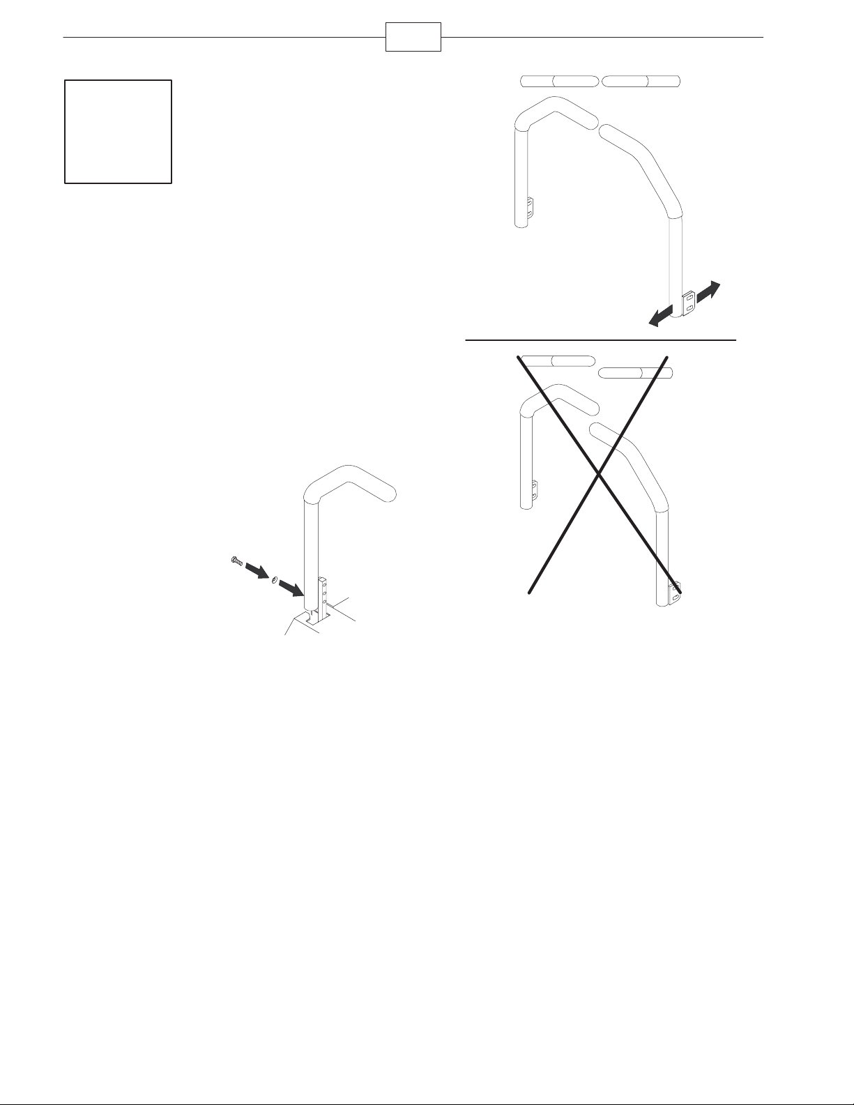
Installing the Roll Over
Protection System (ROPS)
Parts needed for this step:
Procedure
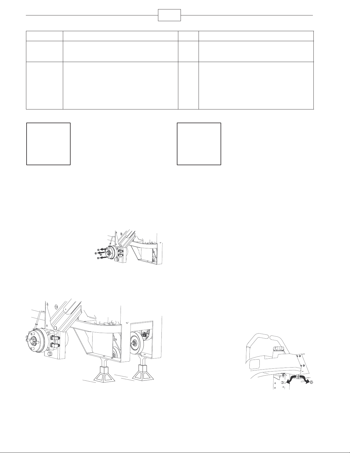
1. Remove the wheel
nuts from both sides of
the vehicle.
2. Remove the right
angle retaining plate
from the crate and the
wheel hub.
3. Raise the back of the machine up and support it
with jack-stands.
m–6858
Qty. Part
1 Roll bar, right section
1 Roll bar, left section
1 Roll bar, center section
2 Bolt, 3/8 x 4–1/2 inches
2 Lock nut, 3/8 inch
4 Bolt, 3/8 x 1 inch
8 Curved washer
6 Flange nut, 3/8 inch
2 Bolt, 1/2 x 3-1/4 inches
2 Flange nut, 1/2 inch
Procedure
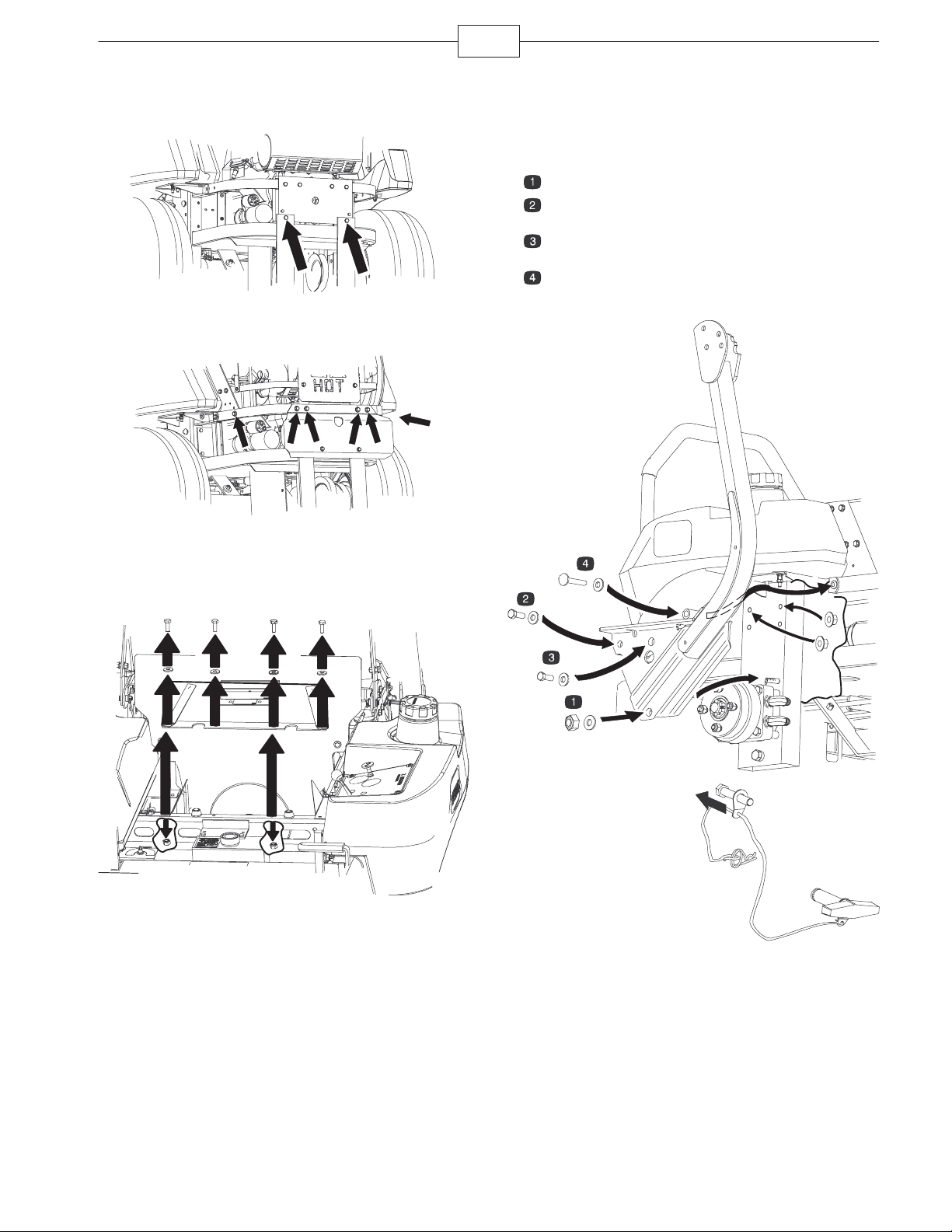
1. Remove and discard
the fuel tank mounting
bolt and nut from under
the tank on each side.
m–6857
Page 3
3
2. For an air cooled machine, loosen the two bottom
bolts in the rear bumper.
m–6886
3. For a liquid cooled machine, loosen the two side
and four back bolts in the rear bumper.
m–6885
Note: Step 4 is needed for international mowers only.
4. For internationl mowers, remove the bolts,
washers and nuts holding the rubber flap in front of
the motor.
5. Install the bolts in the order shown in the figure
below.
6. Loosely install the right and left roll bar sections
to the frame, in numbered order as follows:
Lock nut (3/8 inch), curved washer
Bolt (3/8 x 1 inch), curved washer, and flange nut
(3/8 inch)
Bolt (3/8 x 1 inch), curved washer, and flange nut
(3/8 inch)
Bolt (3/8 x 4-1/2 inches), curved washer, and
flange nut (3/8 inch)
m–7655
m–6854
7. Install the lanyard
clips onto the 2 bolts
(1/2 x 3-1/4 inches).
Note: Make sure the
bent tab points toward
the head of the bolt.
m–6892
Page 4
4
5
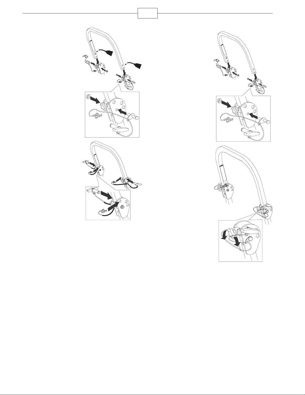
8. Lightly oil the ends
of the center roll bar
section.
9. Loosely install the
center roll bar section,
using 2 bolts
(1/2 x 3-1/4 inches) and
2 flange nuts (1/2 inch).
Note: Make sure the
bolts are installed on the
outside of the roll bar.
Note: Make sure the
lanyard tab is install as
shown and points
forward.
10. Raise the roll bar
into the upright position
and secure it with the
pins and hairpin cotter
pins fastened to the
lanyards.
m–6891
m–6893
11. Tighten the center
roll bar bolts
(1/2 x 3-1/4 inches) so it
rotates freely with some
resistance.
Note: No more than one
thread should be
exposed outside the nut.
12. Torque all lower
fasteners, attached to
the machine frame, to
30 ft–lb.
13. Tighten the front
handles against the
center roll bar ends.
14. Tighten the rear
bumper bolts.
m–6891
m–683
Note: Step 15 is needed for international mowers
only.
15. For internationl mowers, install the rubber flap
with the previously removed bolts, washers and nuts.
Page 5
5
Step
4
Checking the Tire Pressure
Parts needed for this step:
None
m–7656
Step
3
Installing the Drive Wheels
Parts needed for this step:
Qty. Part
2 Rear wheels
Procedure
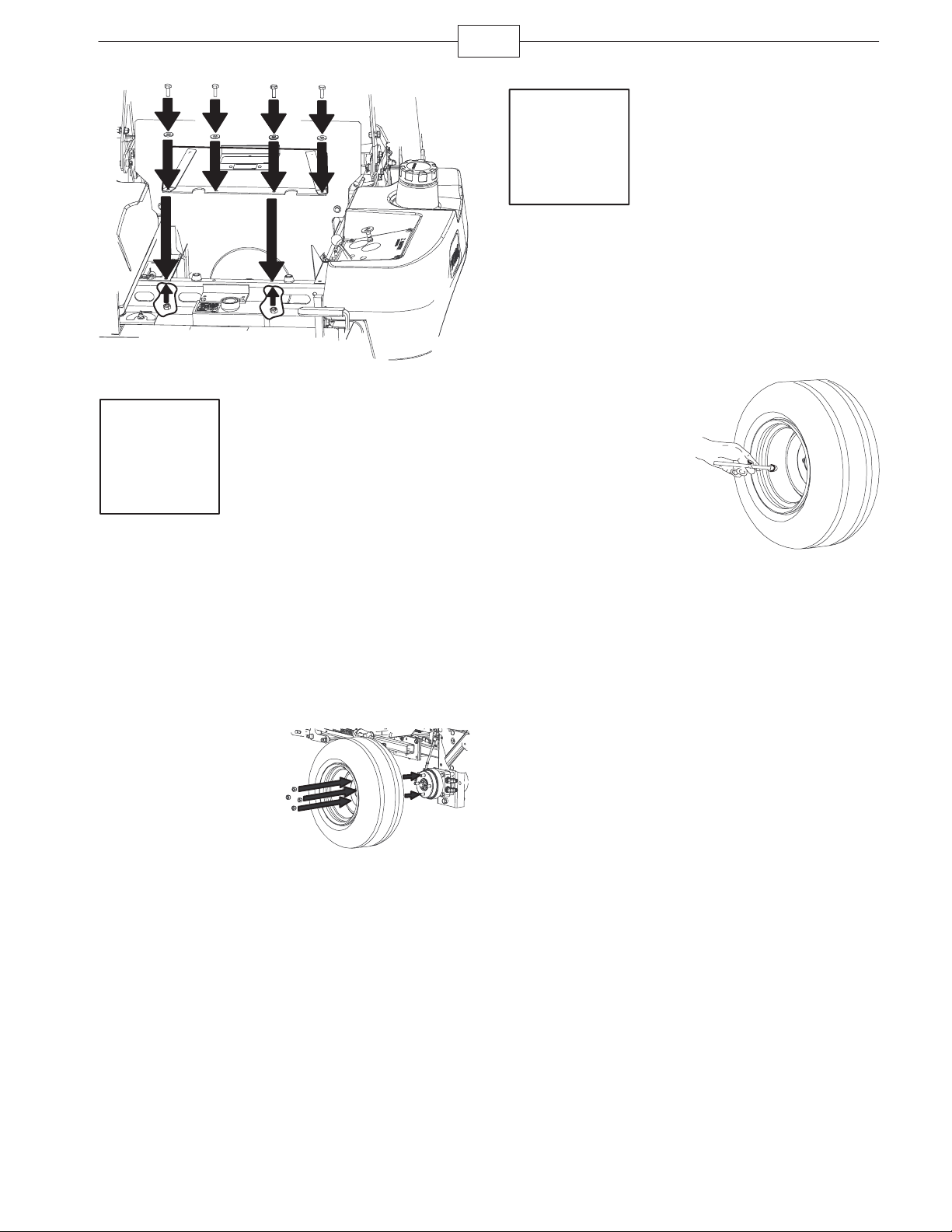
1. Mount the wheels
with the valve stem to
the outside and secure
them with the nuts
previously removed in
Step 1.
2. Torque the nuts to
95 ft-lb (128 N⋅m).
m–6859
Procedure
Check the air pressure
in the front and rear
tires.
Pressure: 13 psi
(90 kPa)
m–6873
Page 6
Step
5
Installing the Motion
Control Levers
Parts needed for this step:
6
Qty. Part
1 Control lever–right
1 Control lever–left
4 Bolt, 3/8 x 1 inch (2 assembled)
4 Curved washer, 3/8 inch (2 assembled)
Procedure
1. Rotate the handles
to the upright position.
2. Loosely install the
levers on the outside,
using 4 bolts and curved
washers.
Note: Install the levers
in the top and middle
holes for the high
position or the middle
and bottom holes for the
low position, as desired.
3. In the neutral position, raise the levers, bringing
them together, and slide them until they are aligned,
then tighten the bolts.
m–6866
m–6867
m–6868
Page 7
Step
6
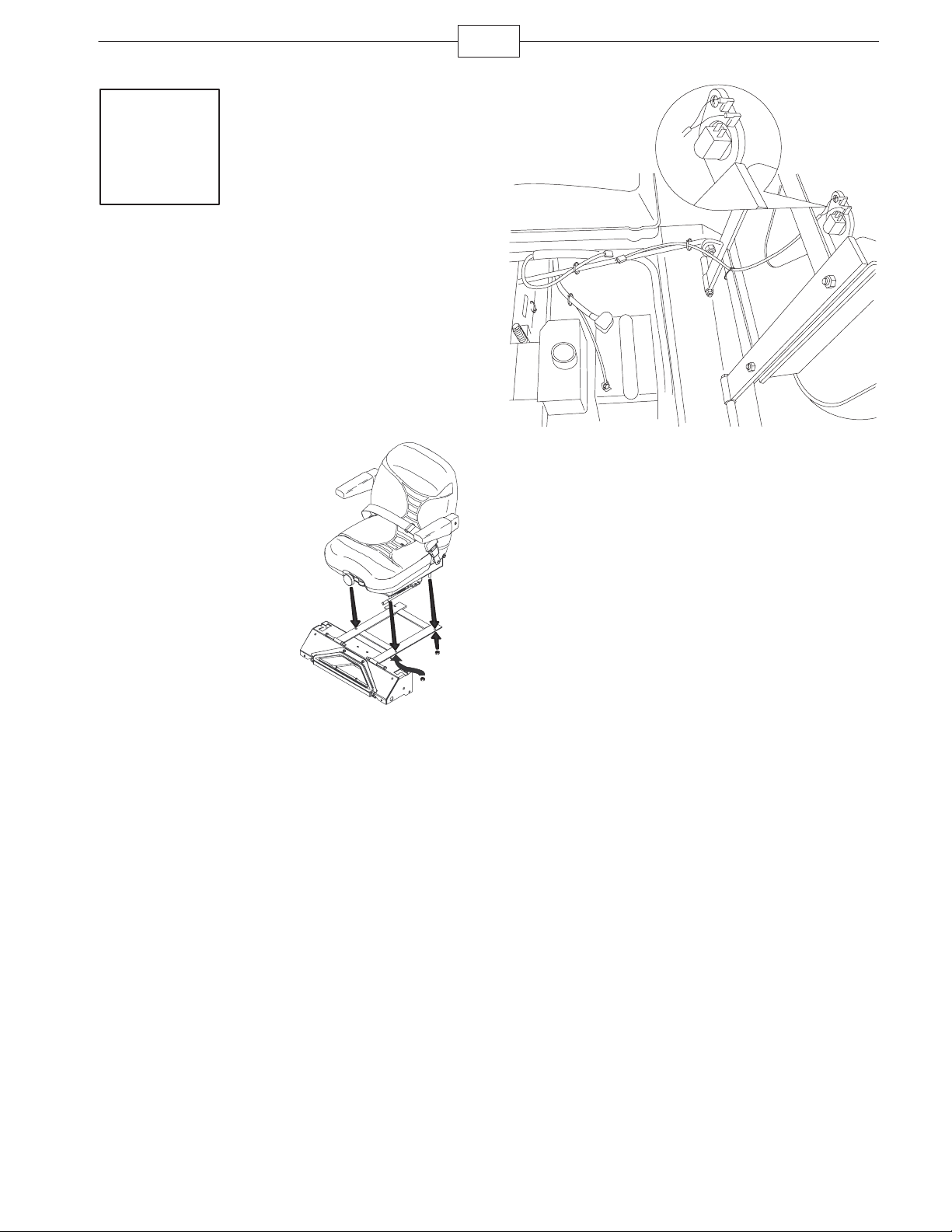
Installing the Seat
Parts needed for this step:
Qty. Part
1 Seat
4 Flange nuts (installed on the seat)
7
Procedure
1. Remove the seat
from the crate.
2. Remove the 4
flange nuts from the
studs on the bottom of
the seat.
3. Position the seat
into the holes in the seat
frame.
4. Secure the seat with
4 flange nuts.
m–6860
5. If needed, attach the two connectors onto the
seat switch.
m–6877
Page 8
Step
7
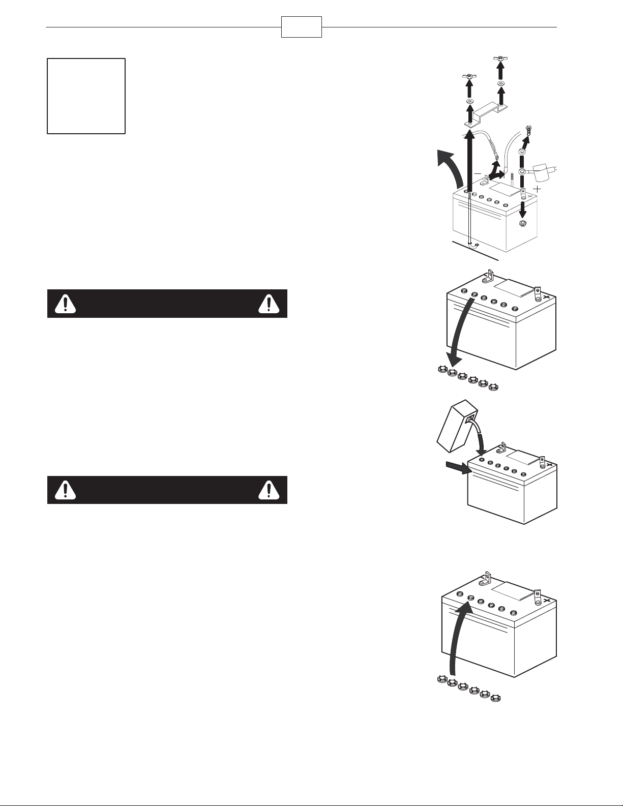
Activating the Battery
Parts needed for this step:
Qty. Part
80
Bulk electrolyte with 1.265 specific gravity
ounces
Procedure
(Purchase from a battery supply outlet.)
Danger
8
1. Remove the battery.
Refer to the
Manual
Important: Do not add
electrolyte while the
battery is in the
machine. You could spill
it, causing corrosion.
2. Clean the top of the
battery and remove the
vent caps.
Operator’s
for instructions.
m–6850
Battery electrolyte contains sulfuric acid which is
a deadly poison and causes severe burns.
Do not drink electrolyte and avoid contact
with skin, eyes or clothing. Wear safety
glasses to shield your eyes and rubber gloves
to protect your hands.
Fill the battery where clean water is always
available for flushing the skin.
Follow all instructions and comply with all
safety messages on the electrolyte container.
Warning
CALIFORNIA
Proposition 65 Warning
Battery posts, terminals, and related accessories
contain lead and lead compounds, chemicals
known to the State of California to cause cancer
and reproductive harm.
handling.
Wash hands after
m–6851
3. Slowly pour
electrolyte into each
battery cell until the level
is up to the upper line
on the battery case.
Important: Do not
overfill the battery.
m–6853
4. Wait five to ten minutes, then add electrolyte, if
necessary, until the electrolyte level is up to the
upper line on the battery case.
5. Install battery filler
caps.
6. Charge the battery and then install it on the
machine. Refer to the
instructions.
Operator’s Manual
for
m–6852
Page 9
9
Warning
Charging the battery produces gasses that can
explode and cause serious injury.
Keep cigarettes, sparks and flames away from
the battery.
Make sure the ignition switch is off.
Ventilate when charging or using the battery
in an enclosed space.
Important: Do not run the machine with the battery
disconnected; electrical damage may occur to the
engine computer.
Important: Do not jump start an EFI machine, or you
may damage the electronic control unit.
Step
8
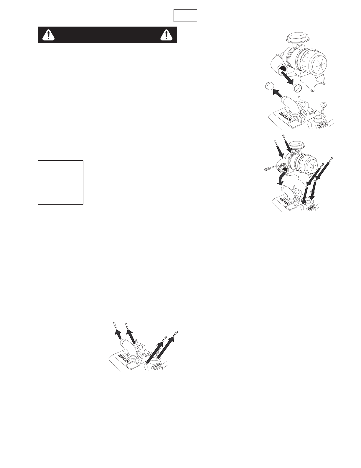
Installing the Air Cleaner
on Kohler Engines
Parts needed for this step:
3. Remove the plastic
plugs.
4. Align the holes in
the air cleaner bracket
with holes in the valve
covers.
5. Secure the bracket
and valve covers with
the 4 bolts removed
previously.
6. Torque the bolts to
70 in-lb (5 N⋅m).
7. Install the air
cleaner hose over the
air intake elbow on the
engine and secure it
with a hose clamp.
m–6870
m–6871
Qty. Part
1 Air cleaner
1 Hose clamp
Procedure
1. Remove the air cleaner from the crate, keeping
the bracket together with it.
2. Remove the top 2
valve cover mounting
bolts from both valve
covers.
m–6869
Page 10
Step
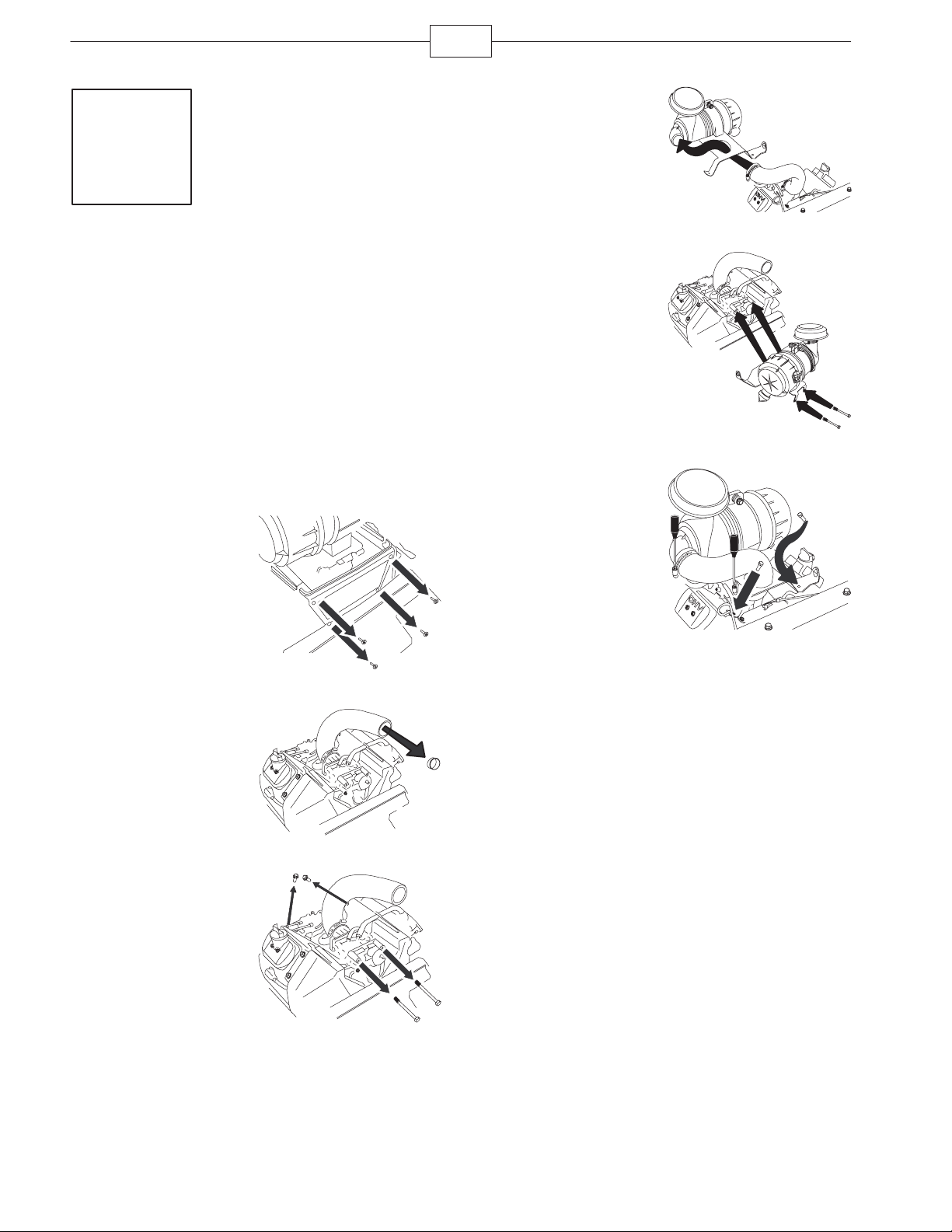
9
Installing the Air Cleaner
on 25hp Kawasaki Engines
Parts needed for this step:
Qty. Part
1 Air cleaner
1 Hose clamp
Procedure
1. Remove the air cleaner from the crate, keeping
the bracket together with it.
2. Remove the 4
screws holding the front
plastic cover on the front
of the engine.
m–7292
10
6. Install the hose into
the air cleaner base.
7. Align the holes in
the air cleaner bracket
with holes in the valve
covers.
8. Install the long
carburetor bolts into the
air cleaner base and into
the carburetor.
9. Install the hose
clamp onto the hose and
install the hose to the air
cleaner.
10. Install the bolts into
the back of the air
cleaner bracket and into
the motor.
11. Tighten the hose
clamps.
m–7294
m–7295
m–7296
3. Remove the plastic
plug.
4. Remove the 2 bolts
from the back of the
engine.
5. Remove the 2 long
bolts that run through
the carborateur.
m–7297
m–7293
Page 11
Step
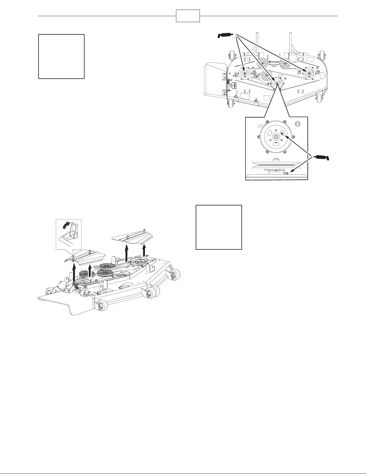
10
Checking the Spindles for
Grease
Parts needed for this step:
Qty. Part
1 tube Number 2 general purpose lithium base or
molybdenum base grease. (Purchase
separately.)
11
Procedure
Important: Check the cutting unit spindles to
make sure they are greased before starting the
engine.
1. Remove the belt covers.
m–6824
2. Grease the fittings on the three spindle bearings.
Add grease until it comes out of the lower seals.
m–6822
3. Install the belt covers.
Step
11
Preparing the Side
Discharge Chute
Parts needed for this step:
None
Procedure
Remove the plastic tie holding the side discharge
chute up and lower the chute into place.
Page 12

12
Step
12
Checking the Machine Before Delivery to the Customer
Parts needed for this step:
None
Procedure
Before delivering the machine to the customer, ensure that you perform or have performed the procedures listed
in the following table and initial each when finished. Refer to the
these procedures.
Initial Check Procedure
Operator’s Manual
for instructions on performing
Check the tire pressure
Check the level of the mower.
Check that all mower spindles are greased.
Check the engine oil level.
Check the hydraulic fluid level.
On liquid cooled machines, check the level of the coolant in the radiator.
Check the adjustment of the parking brake.
Ensure that the machine tracks correctly; refer to the
Check the safety interlock system; refer to the
Ensure that the PTO works.
Check all fasteners you installed to ensure that they are tight.
When you finish setting up the machine, sign and date in the space provided below:
Operator’s Manual
Operator’s Manual
for the adjustment procedure.
.
Signature: Date:
Page 13

13
Step
13
Delivering the Machine to the Customer
Parts needed for this step:
Qty. Part
1
Operator’s Manual
1
Parts Catalog
1
Engine Owner’s Manual
1 Registration card
1 Safety video
2 Key
Procedure
At delivery, complete the items listed in the following table and initial each when finished.
Model Number: Serial Number:
Page 14

14
Dealer
Initial
Customer
Initial
Check Procedure
Show the customer where the following features are located and how they function:
• Fuel Tank Caps
• Oil Fill Tube/ Oil dipstick
• Oil Filter
• Oil Drain
• Spark Plug(s)
• Air Filter
• Radiator Coolant (Liquid Cooled Only)
• Hydraulic fluid reservoir
• Hydraulic filter
• Battery
• Ignition Switch
• Throttle Lever
• Choke (Not on an EFI machine)
• Power Take Off Switch (PTO)
• Motion Control Levers
• Parking Brake
• Mower Height–of–Cut Lever
• Lift Assist Lever
• Z Stand
• Adjustable Seat
• Hydraulic Bypass
• Rollover Protection System (ROPS)
• Flow Baffle
Refer to the operator’s manual to point out safety procedures, operation, and
maintenance procedures.
Review the warranty statement as shown in the
Describe the post sale service procedures for your store.
Assist the customer in filling out and mailing the registration card or register online at
www.Toro.com.
Make sure that the customer receives the
Owner’s Manual, Set Up Instructions
Assist the customer in loading the mower.
, and safety video.
Operator’s Manual
.
Operator’s Manual, Parts Catalog
, and
Engine
Note: When you, the dealer representative, have finished delivering the machine to the customer, sign and date
in the space provided below and keep a copy of this page for dealer records:
Signature: Date:
Signature: Date:
Page 15

15
Page 16

16
 Loading...