

Toro 74225 Parts Catalogue

Form No. 3326–826
Z253
Z–Master with 62” SFS Side Discharge Mower
Model No. 74225—210002101 and Up
Parts Catalog
Ordering Replacement Parts
To order replacement parts, please supply: the part
number, the quantity, and the description of each
part desired.
Understanding Reference Numbers
Each identified part in an illustration has a reference
number. The reference number for a part also appears in
the parts list, along with other information about the part.
This catalog uses two special reference number formats,
one to indicate parts in a service assembly and another
to indicate the quantity of a given part in an illustration.
Service Assembly Reference Numbers
Parts in service assemblies have reference numbers in
the form a:b.
the entire service assembly and the b represents a
sequential number unique to each part within the service
assembly.
The a represents the reference number of
The TORO Company — 2001
All Rights Reserved
For example, a wheel assembly might be identified by
reference number 6, the tire by 6:1, the valve by 6:2,
and the wheel by 6:3. When you order the assembly
identified by reference number 6, you receive all parts
identified by reference numbers 6:1, 6:2, and 6:3.
However, you may also order any part individually.
Reference numbers of this type appear in illustrations
and in part lists.
Reference Numbers Indicating Quantity
In an illustration, if a reference number indicates more
than one part, the reference number has the form nX y.
The n represents the quantity of the part, the X is the
multiplication symbol, and the y represents the reference
number.
For example, in an illustration, the reference number
2X 37 means that two of the parts identified by reference
number 37 are indicated.

3326–826
Contents
Description Page Description Page
Front Frame Assembly 3. . . . . . . . . . . . . . . . . . . . .
Caster and Wheel Assembly 4. . . . . . . . . . . . . . . .
Rear Frame and Wheel Assembly 5. . . . . . . . . . .
Brake and Wheel Hub Assembly 6. . . . . . . . . . . .
Control Panel Assembly 7. . . . . . . . . . . . . . . . . . . .
Hydraulic System Assembly 8. . . . . . . . . . . . . . . .
Hydraulic System Assembly (Continued) 9. . . . .
Tank and Fuel Line Assembly 10. . . . . . . . . . . . . . .
Shield and Clutch Assembly 11. . . . . . . . . . . . . . . .
Shield and Clutch Assembly (Continued) 12. . . . .
Idler Assembly 13. . . . . . . . . . . . . . . . . . . . . . . . . . . .
Electrical System Assembly 14. . . . . . . . . . . . . . . . .
Frame and Deck Assembly 15. . . . . . . . . . . . . . . . .
Deck, Deflector and Roller Assembly 16. . . . . . . . .
Spindle and Pulley Assembly 17. . . . . . . . . . . . . . .
Belt and Idler Arm Assembly 18. . . . . . . . . . . . . . . .
Stand Assembly 19. . . . . . . . . . . . . . . . . . . . . . . . . . .
Electrical Schematic 20. . . . . . . . . . . . . . . . . . . . . . .
Crankshaft Assembly – Group 1
Kohler CH23S–76550 21. . . . . . . . . . . . . . . . . . . .
Crankcase Assembly – Group 2
Kohler CH23S–76550 22. . . . . . . . . . . . . . . . . . . .
Oil Pan/Lubrication Assembly – Group 3
Kohler CH23S–76550 23. . . . . . . . . . . . . . . . . . . .
Head/Valve/Breather Assembly – Group 4
Kohler CH23S–76550 24. . . . . . . . . . . . . . . . . . . .
Ignition/Electrical Assembly – Group 5
Kohler CH23S–76550 25. . . . . . . . . . . . . . . . . . . .
Blower Housing and Baffle Assembly – Group 6
Kohler CH23S–76550 26. . . . . . . . . . . . . . . . . . . .
Starting System Assembly – Group 7
Kohler CH23S–76550 27. . . . . . . . . . . . . . . . . . . .
Fuel System Assembly – Group 8
Kohler CH23S–76550 28. . . . . . . . . . . . . . . . . . . .
Engine Control Assembly – Group 9
Kohler CH23S–76550 29. . . . . . . . . . . . . . . . . . . .
Air Intake/Filtration Assembly – Group 10
Kohler CH23S–76550 30. . . . . . . . . . . . . . . . . . . .
Exhaust Assembly – Group 11
Kohler CH23S–76550 31. . . . . . . . . . . . . . . . . . . .
Accessories
Description Model / Part No. Description Model / Part No.
High Suspension Seat 74210. . . . . . . . . . . . . . . . . . . . .
Foot Lift Assist 78473. . . . . . . . . . . . . . . . . . . . . . . . . . . .
Roll Over Protection System Kit 78480. . . . . . . . . . . . .
Stripping Kit 30163. . . . . . . . . . . . . . . . . . . . . . . . . . . . . .
Hitch Kit 99–8925. . . . . . . . . . . . . . . . . . . . . . . . . . . . . . .
Atomic Blade Assembly 104–1303. . . . . . . . . . . . . . . .
Z Recycler Kit (62in) 100–9600. . . . . . . . . . . . . . . . . . .
Spark Arrester Kit 105–1672. . . . . . . . . . . . . . . . . . . . .
Air Filter Kit 99–4663. . . . . . . . . . . . . . . . . . . . . . . . . . . .
Filter Minder 99–4664. . . . . . . . . . . . . . . . . . . . . . . . . . .
Part Description Abbreviations
Part descriptions in this catalog may include the following abbreviations.
Abbreviation Meaning Abbreviation Meaning
AR as required. . . . . . . . . . . . . . . . . . .
ASM assembly. . . . . . . . . . . . . . . . . .
CARR carriage. . . . . . . . . . . . . . . .
DEG degrees. . . . . . . . . . . . . . . . . .
FH flat head. . . . . . . . . . . . . . . . . . .
GA gauge. . . . . . . . . . . . . . . . . . .
HF hex flange. . . . . . . . . . . . . . . . . . .
HH hex head. . . . . . . . . . . . . . . . . . .
HHF hex head flange. . . . . . . . . . . . . . . . . .
HLH hex lag head. . . . . . . . . . . . . . . . . .
HJ hex jam. . . . . . . . . . . . . . . . . . . .
HOC height-of-cut. . . . . . . . . . . . . . . . . .
HS hex socket. . . . . . . . . . . . . . . . . . .
HSBH hex socket button head. . . . . . . . . . . . . . . . .
HSFH hex socket flat head. . . . . . . . . . . . . . . . .
HSH hex socket head. . . . . . . . . . . . . . . . . .
HWH hex washer head. . . . . . . . . . . . . . . . .
HWHTF hex washer head thread forming. . . . . . . . . . . . . . .
INC incorporated. . . . . . . . . . . . . . . . . . .
LH left hand. . . . . . . . . . . . . . . . . . . .
NI nylon insert. . . . . . . . . . . . . . . . . . . .
PPH Phillips pan head. . . . . . . . . . . . . . . . . .
PTH Phillips truss head. . . . . . . . . . . . . . . . . .
PTO power take off. . . . . . . . . . . . . . . . . .
RH right hand. . . . . . . . . . . . . . . . . . .
SFH slotted fillister head. . . . . . . . . . . . . . . . . .
SHH slotted hex head. . . . . . . . . . . . . . . . . .
SQH square head. . . . . . . . . . . . . . . . . .
SHWH slotted hex washer head. . . . . . . . . . . . . . . .
SPH slotted pan head. . . . . . . . . . . . . . . . . .
SRH slotted round head. . . . . . . . . . . . . . . . . .
STD standard. . . . . . . . . . . . . . . . . .
TAP self tapping. . . . . . . . . . . . . . . . . .
TTH Torx truss head. . . . . . . . . . . . . . . . . .
2
22
15
37
18
24
21
10
19
22
24
17
16
24
36
20
10
25
5
1:4
11
11
3:2
6
3:5
13
1:2
27
12
14
3
7
8
9
10
25
24
23
26
3326–826
3:4
3:3
1
10
1:3
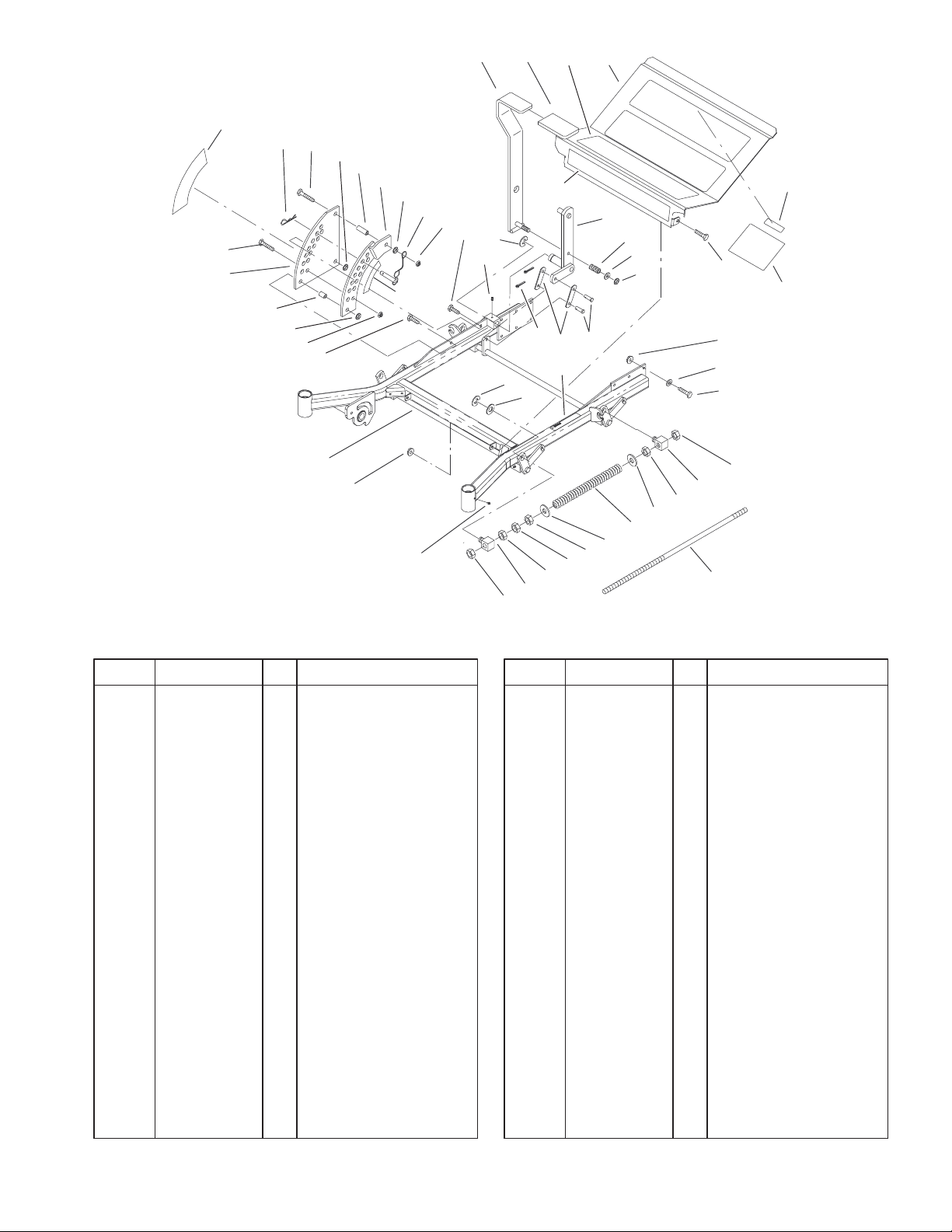
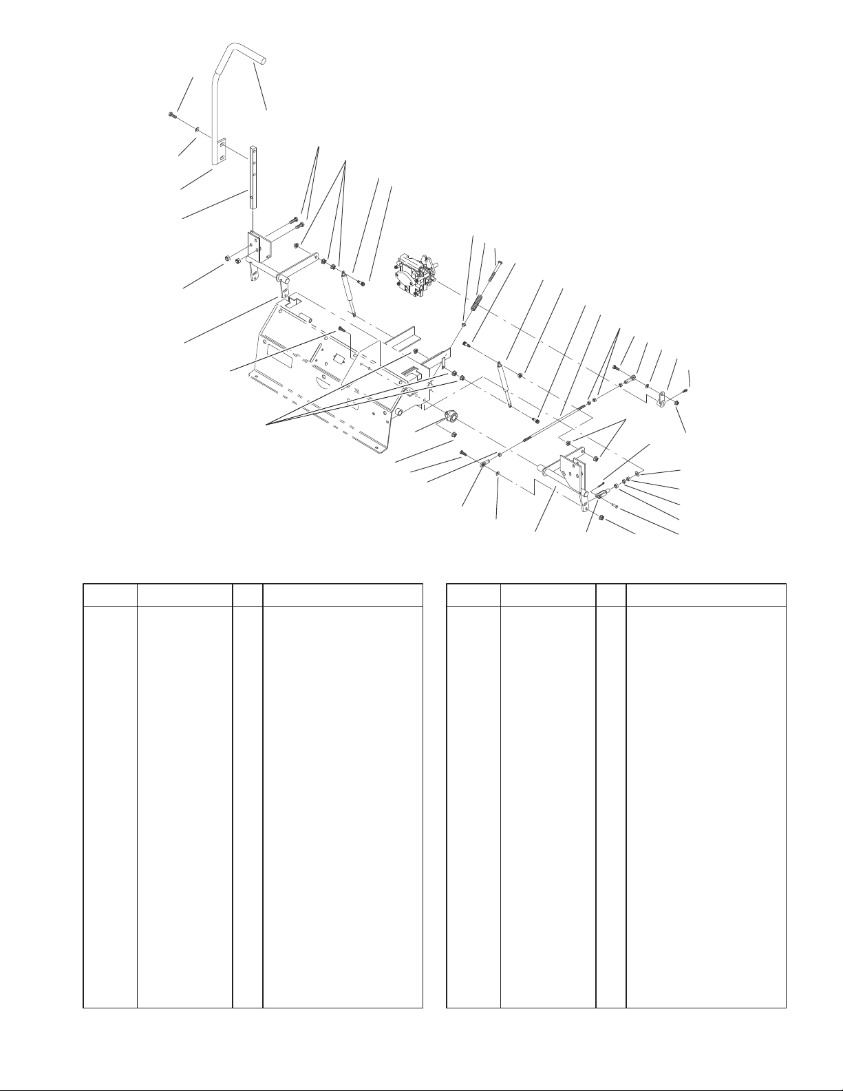
Front Frame Assembly
DescriptionPart No. Qty.Ref. No. DescriptionPart No. Qty.Ref. No.
1 104–5132 1 Frame ASM
1:2 1–633818 1 Decal–Warning
1:3 1–811010 2 Plug
1:4 302–19 5 Fitting–Grease
3 100–6509 1 Floorpan ASM
3:2 1–633553 3 Pad–Antiskid
3:3 1–633766 1 Decal–Check
3:4 98–5954 1 Decal–Missing, Cover
3:5 1–633737 1 Decal–Z–Master
5 1–632324–03 1 Lever–Lift
6 1–633295 1 Grip–Lever, Lift
7 1–632219–03 1 Arm–Lift, Deck
8 1–633325 1 Spring–Compression
9 3256–24 1 Washer–Flat
10 3296–39 5 Nut–Lock, NI
11 32151–103 5 Ring–Snap
12 1–633068 2 Arm–Lift, Deck
13 3272–10 2 Pin–Cotter
14 283–2 2 Pin–Clevis
15 1–633889–01 1 Plate–Lift, Deck
16 1–632899–01 1 Plate–Lift, Deck
17 1–633082 1 Bushing–Lever, Lift
18 1–633080 1 Bushing–Lever, Lift
19 323–13 1 Screw–HH
20 1–633097 1 Pin–Hitch w/Lanyard
21 1–806005 1 Pin–Hair
29
30
33
31
32
34
29
33
29
30
29
28
22 323–9 2 Screw–HH
23 98–5975 12 Washer–Belleville
24 3290–357 15 Nut–Flange, Lock
25 323–6 3 Screw–HH
26 323–7 12 Screw–HH
27 3256–29 4 Washer–Flat
28 1–633096 2 Rod–Lift, Deck
29 3217–11 8 Nut–Hex
30 1–633441 4 Swivel–Deck Mount,
Rear
31 3256–7 2 Washer–Flat
32 1–633064 2 Spring–Support, Deck
33 3218–6 4 Nut–Jam
34 3256–7 2 Washer–Flat
36 1–633706 1 Decal–Height, Deck
37 1–633345 1 Decal–Height, Deck
Sheet No.:2
3
3326–826
1
2
3
4
1 1:5
1 1:4
1 1:1
11
22
1 1:6
5
4
7
8
1 1:6:1
5
21
1 1:6:2
1 1:6:3
1 1:3
Sheet No.:3
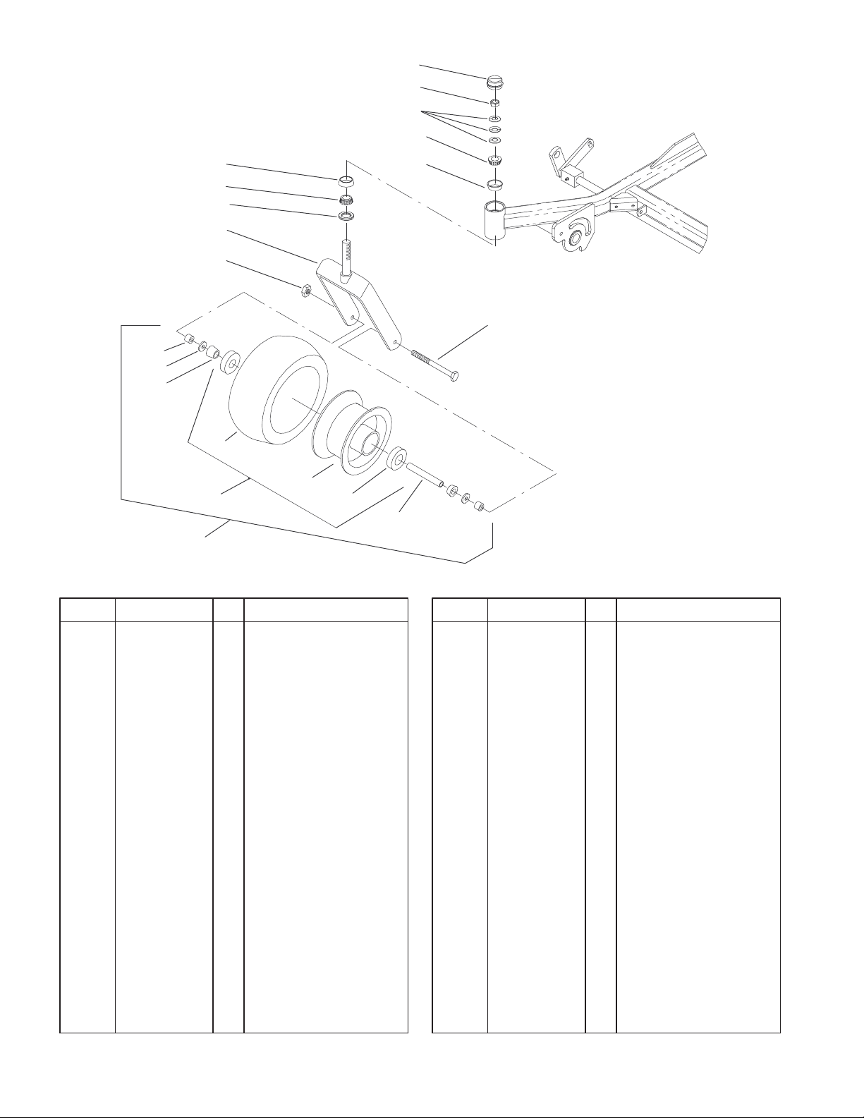
Caster and Wheel Assembly
DescriptionPart No. Qty.Ref. No. DescriptionPart No. Qty.Ref. No.
1 1–543513 2 Cap–Grease
2 3296–51 2 Nut–Lock, NI
3 1–633508 6 Washer–Belleville
4 254–94 4 Bearing–Taper/Cone
5 254–72 4 Bearing–Taper/Cup
7 1–543511 2 Seal–Grease
8 1–642111–01 2 Caster
11 1–644251 2 Caster Wheel ASM
11:1 1–633585 2 Bearing–Cone,
Tapered
11:3 1–633959 1 Spacer–Caster, Front
11:4 1–633580 2 Seal–Bearing
11:5 1–633581 2 Spacer–Bearing
11:6 1 Wheel & Tire ASM
11:6:1 1–523009 1 Tire
11:6:2 1–633987 1 Wheel
11:6:3 1–633584 2 Bearing–Cup
21 325–24 2 Screw–HH
22 3296–45 2 Nut–Lock, NI
4
3326–826
34
2:3
2:4
2:7
2:2
2
2:5
2:1
2:6
20
21
14
13:2
13
23
16
11:2
17
9
27
24
31
3330
25
28
11
15
26
13:3
42
22
10
13:4
3
4
44
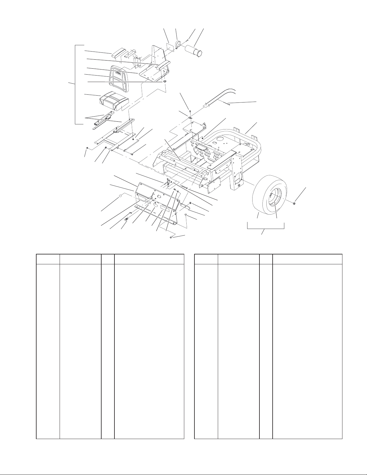
Rear Frame and Wheel Assembly
DescriptionPart No. Qty.Ref. No. DescriptionPart No. Qty.Ref. No.
1 1–633964–03 1 Stop–Brake, Park
2 1–633705 1 Seat w/Tracks
2:1 103–0290 1 Cushion–Bottom, Seat
2:2 104–7754 1 Cushion – Back, Seat
2:3 1–633710 1 Cushion–Armrest, RH
2:4 1–633711 1 Cushion–Armrest, LH
2:5 1–543401 4 Spacer–Track
2:6 1–643255 1 Track–Seat, 4”
2:7 1–633859 1 Frame–Seat
4 322–3 6 Screw–HH
5 323–6 2 Screw–HH
9 1–633696 1 Cable–Throttle
10 1–603336 1 Control–Choke
11 100–4261 1 Rear Frame ASM
11:2 103–0245 1 Decal–Console, Top
12 1–633970 2 Wheel & Tire ASM
12:1 1–633993 1 Tire
12:2 1–633992 1 Wheel
13 99–4623 1 Console ASM
13:2 100–4311 1 Decal–Panel, Control
13:3 103–0262 1 Decal–Valve, Fuel
13:4 98–4387 1 Decal–Protection, Ear
14 1–632187–03 1 Frame – Seat
15 242–50 8 Nut – Lug
16 1–633293 1 Rod–Holdup, Seat
17 322–5 1 Screw–HH
18
19
21
1
29
5
12:1
12
12:2
Sheet No.:4
18 323–21 2 Screw–HH
19 3296–2 2 Nut–Lock
20 3296–29 1 Nut–Lock
21 3296–39 4 Nut–Lock, NI
22 1–807513 2 Bolt–CARR
23 32128–20 4 Nut–HF
24 1–513762 1 Clip–Loom
25 1–303335 1 Tie–Plastic
26 1–513592 1 Knob–Ball, Red
27 321–4 1 Screw–HH
28 32128–33 1 Nut–HF
29 1–513658 2 Bumper–Catcher,
Grass
30 2412–120 2 R–Clamp
31 32104–76 2 Screw
33 74–0720 1 Tube–Manual
34 99–4693 1 Decal–Toro
42 99–4628 1 Decal–Z253
44 3256–23 6 Washer–Flat
5
3326–826
24
12
18
5
27
13
19
23
27
3
23
19
13
27
1
17
1
4
27
19
13
22
23
14
25
3
26
2
26
23
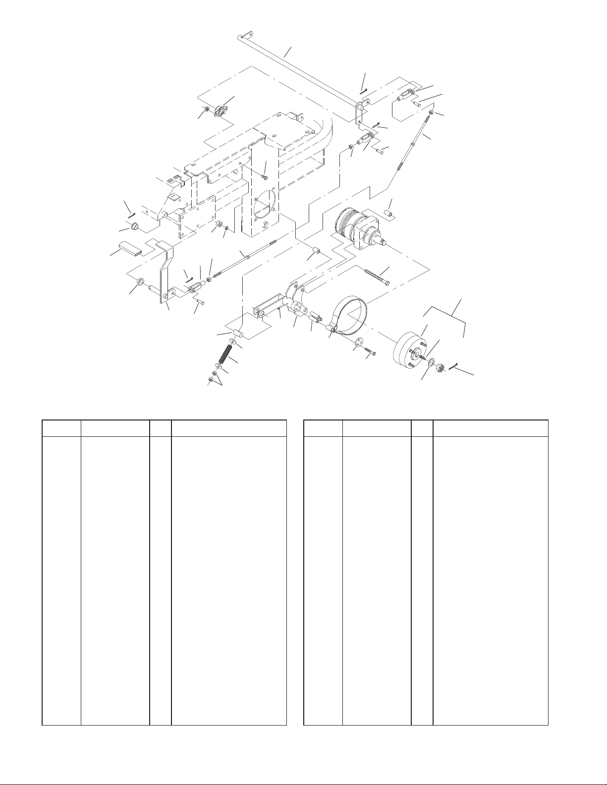
Brake and Wheel Hub Assembly
DescriptionPart No. Qty.Ref. No. DescriptionPart No. Qty.Ref. No.
1 1–513140 2 Bearing–Control
2 1–633454 2 Spring–Brake
3 1–633477 3 Rod–Brake
4 1–634500 1 Brake Lever/Grip ASM
5 1–632217–03 1 Shaft–Brake
6 103–0352–03 2 Bracket–Brake
7 1–523157 2 Washer–Spacer
9 103–0355 2 Band–Brake
10 1–633380 4 Spacer–Wheel, Short
11 1–633382 4 Spacer–Wheel, Long
12 1–633102 2 Bearing–Flange, Side
13 1–633131 4 Yoke–Linkage, Brake
14 1–633144 2 Pin–Trunion
15 103–0590 2 Hub–Wheel w/Studs
15:1 103–0589 1 Hub–Wheel
15:2 1–633926 4 Stud–Heel
17 1–633268 1 Grip–Lever, Brake
18 323–4 4 Screw–HH
19 1–808285 4 Pin–Clevis
20 325–17 8 Screw–HH
21 1481 2 Fitting–Grease
22 103–0131 8 Nut–Square
23 3219–3 8 Nut–HH
24 3290–357 4 Nut–Flange, Lock
25 3253–7 8 Washer–Lock
26 3256–4 4 Washer–Flat
21
11
10
6
30
9
31
29
20
15
15:1
15:2
7
28
Sheet No.:5
27 3272–10 7 Pin–Cotter
28 1–806800 2 Pin–Cotter
29 322–9 6 Screw–HH
30 103–0384 6 Spacer
31 103–0374 2 Retainer–Band, Brake
6
11
3326–826
22
11:1
23
2
34
3
8
18
25
14
21
34
35
Control Panel Assembly
DescriptionPart No. Qty.Ref. No. DescriptionPart No. Qty.Ref. No.
1 1–303105 2 Yoke–Adjustable
2 98–5975 4 Washer–Belleville
3 1–523027 2 Damper–Control
4 1–543017 2 Balljoint–RH
5 1–603735 2 Bushing–Flanged,
Nylon
6 1–603737 2 Bolt–Return, Neutral
7 1–603807 2 Spring–Return,
Neutral
8 1–403180 4 Screw–HH
11 103–0632 1 RH Lever/Grip ASM
11:1 1–633257 1 Grip–Control, Motion
12 1–632208–03 2 Arm–Control, Pump
13 1–642319 1 Control–Motion, LH
14 1–642320 1 Control–Motion, RH
15 1–633153 2 Linkage–Pump/Lever
16 1–633102 4 Bearing–Flange, Side
17 1–633152 2 Balljoint–Thread, LH
18 103–0407 2 Arm–Shaft, Control
20 322–6 4 Screw–HH
21 323–4 8 Screw–HH
22 323–6 4 Screw–HH
23 323–9 6 Screw–HH
24 1–803022 2 Screw
25 3296–39 6 Nut–Lock, NI
26 3219–2 10 Nut–Hex
20
16
27
5
7
6
8
3
34
8
15
26
20
4
30
12
24
34
32
34
29
26
17
30
13
1
34
28
26
33
27 3220–20 2 Nut–Jam
28 3220–2 2 Nut
29 3256–2 2 Washer–Flat
30 3256–3 4 Washer–Flat
32 3272–5 2 Pin–Cotter
33 1–808280 2 Pin–Clevis
34 32128–20 16 Nut–HF
35 3290–357 8 Nut–Flange, Lock
*37 103–0631 1 LH Lever/Grip ASM
Sheet No.:6
* Not illustrated
7
3326–826
10
46
40
41
28
31
35
13
47
29
39
12
44
45
37
36
40
21
33
7
30
41
28
10
1 1:1
11:2
22
Sheet No.:7
22
47
51
1
21
11
20
3
17
6
32
24
17
25
17
7
26
2
19
27
14
16
15
16
32
16
2:2
18
43
20
5
9
34
51
48
47
17
33:1
8
1
33:1
33:3
46
38
11
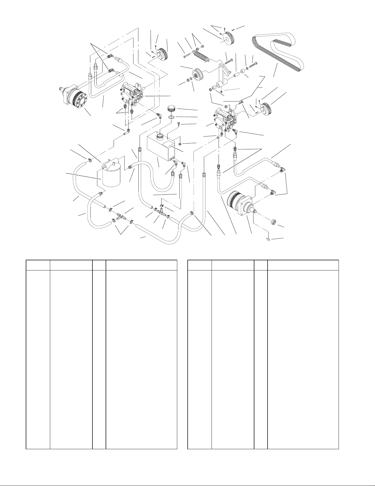
Hydraulic System Assembly
DescriptionPart No. Qty.Ref. No. DescriptionPart No. Qty.Ref. No.
1 1–633774 2 Hose–Upper
2 99–4625 1 Hydraulic Tank ASM
2:2 1–523552 1 Decal–Tank, Hydraulic
3 1–513006 1 Filter–Head
5 1–513167 1 Cap–Reservoir,
Hydraulic
6 1–633750 1 Filter–Hydraulic
6 1–633752 1 Filter–Winter,
Hydraulic
7 1–513840 2 Fitting–90
8 1–522217 1 Low Pressure Hose
ASM
9 1–523103 1 Gasket–Cap, Tank
10 1–633786 4 Fitting–90
11 1–523328 2 Motor–Wheel
11:1 1–809036 1 Nut–HH
11:2 1–807020 1 Key–Woodruff
*11:99 1–000099 1 Kit–Seal
*11:99 1–000139 1 Kit–Bearing
12 1–603384 1 Bushing–Pivot, Idler
13 1–603413 1 Spring–Extension
14 1–603721 1 Fitting–Tee, Hose
15 1–603722 1 Fitting–Tee, Hose
16 1–603826 3 Clamp–Hose
17 1–603827 5 Clamp–Hose
18 1–603987 1 Fitting–Elbow
19 1–603988 1 Fitting–Elbow
20 1–603989 2 Fitting–Elbow
21 1–603990 4 Fitting–Straight
22 1–633775 2 Hose–Lower
24 1–632281 1 Hose ASM
25 1–632282 1 Hose ASM
26 1–632285 1 Hose ASM
27 1–632286 1 Hose ASM
28 1–633568 2 Sheave
29 1–633567 1 Sheave
30 1–633749 1 Belt–Drive, Pump
31 1–633167 1 Sheave–Idler
32 1–633335 2 Hose–Pressure, Low
33 1–634277 1 Bearing Arm ASM
33:1 1–513034 2 Sleeve–Bearing
33:3 302–40 1 Fitting–Grease
34 321–4 2 Screw–HH
35 323–8 1 Screw–HH
36 323–9 1 Screw–HH
37 1–800805 1 Screw–HH
38 323–7 4 Screw–HH
39 1–803022 2 Screw
40 3242–6 2 Screw–Set, SQH
41 3242–4 2 Screw–Set, SQH
43 3256–3 1 Washer–Flat
44 3256–4 1 Washer–Flat
* Not illustrated
8
10
46
40
41
28
31
35
13
47
29
39
3326–826
12
44
45
37
36
22
47
51
1
21
11
20
3
17
6
32
24
17
26
25
17
7
2
19
27
14
16
15
16
32
16
2:2
18
43
20
5
9
34
51
48
47
17
33:1
8
1
33:1
33:3
46
38
11
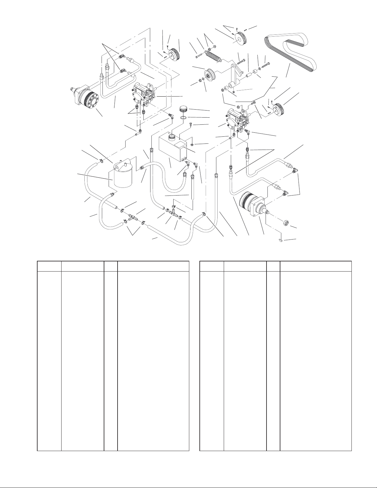
Hydraulic System Assembly (Continued)
40
33
7
21
30
41
28
10
1 1:1
11:2
22
Sheet No.:7
DescriptionPart No. Qty.Ref. No. DescriptionPart No. Qty.Ref. No.
45 13–2840 1 Key–Square
46 1–807272 2 Key–Machine
47 3290–357 8 Nut–Flange, Lock
48 32128–33 2 Nut–HF
51 1–603841 2 Pump–Hydraulic, RH
*51 80–6130 1 Kit–Seal, Overhaul
* Not illustrated
9
3326–826
23
24
10
21
2
22
1
5
1
5
5:3
11
9
20
14
17
4
8
20
19
16
13
UNIT FRONT
15
18
15
18
3
1
1
12
1
3
8
6
7
Sheet No.:8
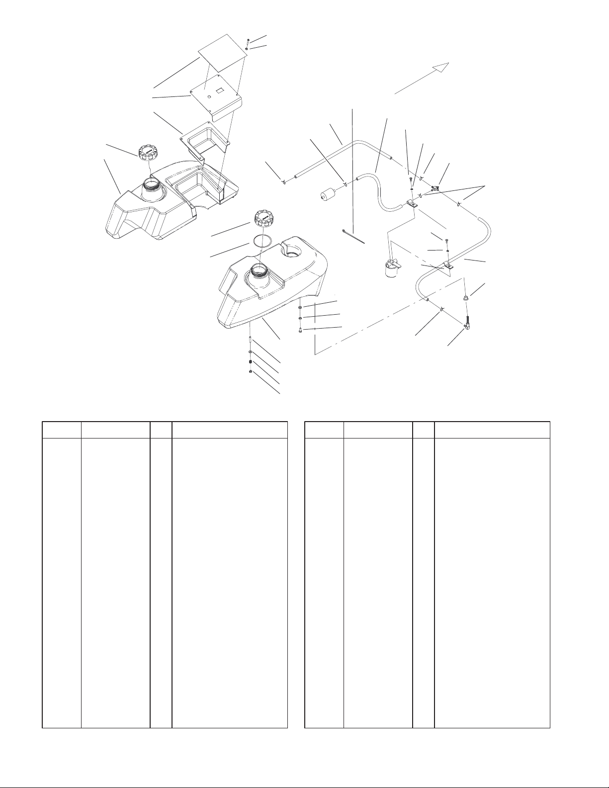
Tank and Fuel Line Assembly
DescriptionPart No. Qty.Ref. No. DescriptionPart No. Qty.Ref. No.
1 1–303077 6 Clamp–Line, Fuel
2 99–4656–03 1 Panel–Control
3 1–513762 2 Clip–Loom
4 1–303335 1 Tie–Plastic
5 88–3980 2 Gas Cap ASM
5:3 88–4010 1 Gasket–Cap, Gas
6 1–513645 2 Bushing–Valve, Fuel
7 1–543277 2 Elbow–Tank, Fuel
8 1–543456 2 Hose–Fuel
9 1–633023 6 Stud
10 104–5100 1 Tank–Fuel, LH
11 104–5101 1 Tank–Fuel, RH
12 1–633347 1 Valve–Fuel
13 103–0216 1 Hose–Fuel
14 1–633349 6 Spring–Tank, Fuel
15 321–3 2 Screw–HH
16 322–3 2 Screw–HH
17 3296–47 6 Nut–Lock, NI
18 3253–3 2 Washer–Lock
19 3253–4 2 Washer–Lock
20 3256–23 8 Washer–Flat
21 99–4632 1 Decal–Panel, Control
22 99–4940 1 Shield–Panel, Control
23 1–803071 4 Screw
24 1–303435 4 Washer–Spring
10
 Loading...