

Page 1
Spindle Repair Module 1
Page 2

Page 3
Z Master 200 Series
1. Stop the engine, remove the key, and
engage the parking brake.
Zerk
2. Remove covers from the cutting unit.
3. Using a floor jack raise the machine until
you can access the underside of the cutting unit.
4. Support the machine using a properly
rated jack stand.
5. Inspect the assembly before removing.
Look for the following:
A. Bent or damaged blade.
B. Missing or unused grease zerk.
C. String, wire, rope, etc. wrapped
around the spindle under the deck.
6. Remove the drive belt(s) from the pulley.
Consult the machine owner's manual for
this procedure.
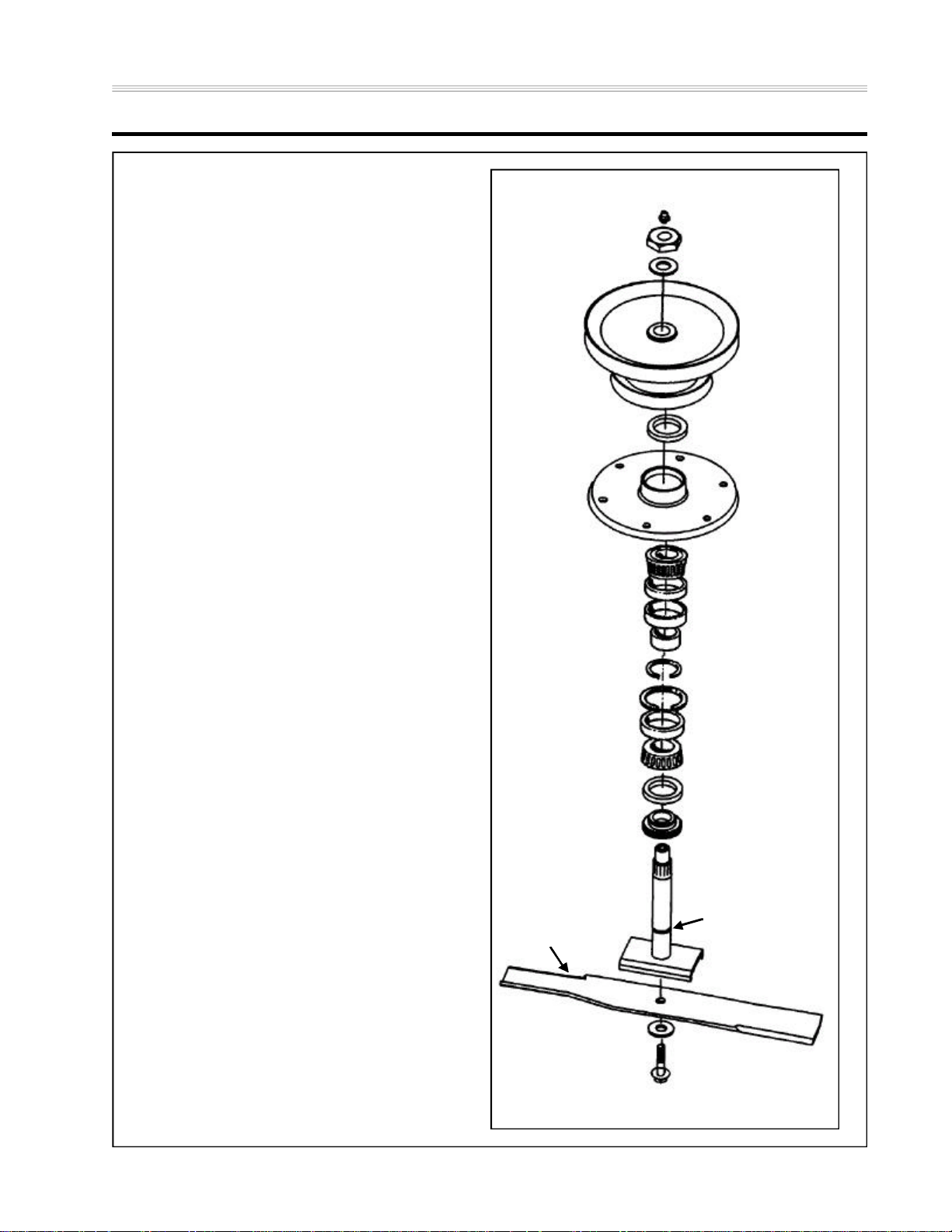
7. Remove the nut and washer retaining the
spindle pulley. Then remove the pulley
from the shaft.
Nut
Hardened Washer
Pulley
Seal
Spindle
Housing
Bearing Cone
Bearing Cup
Large Spacer
Small Spacer
Machine “C” Spacer
8. Unbolt the spindle housing from the deck.
Place spindle assembly on a bench or in a
vise and remove the blade.
9. Remove the spindle shaft from the spindle
housing; it may need to be pressed out of
the housing.
Note: The lower bearing spacer will remain
on the spindle shaft.
10. Inspect the spindle shaft for the
following:
A. Elongated grease axis hole. Normally
this hole is perfectly round, if it is
deformed it is directly a result of
impact.
B. Damaged splines - If the splines are
twisted, it is a sign of impact. If they
are worn, it's an indication that the
assembly was running with the pulley
loose.
Bearing Cup
Spindle Shaft
Blade
Spring Washer
Snap Ring
Bearing Cone
Seal
Bearing Spacer
Grease Axis Hole
Blade Bolt
3Spindle Repair Module
Page 4
Z Master 200 Series
C. Damaged shaft - When the shaft is
worn at the point where the upper
bearing is located in the assembly, it
is a result of the assembly running
loose.
There are two causes for this:
1. Improper torque on the pulley retention nut. This allows individual components of the assembly to move
and wear against other components.
2. Impacts cause the shaft to stretch,
which will lessen the clamp load and
cause the assembly to wear as if
the nut did not have proper torque.
Zerk
Nut
Hardened Washer
Pulley
Seal
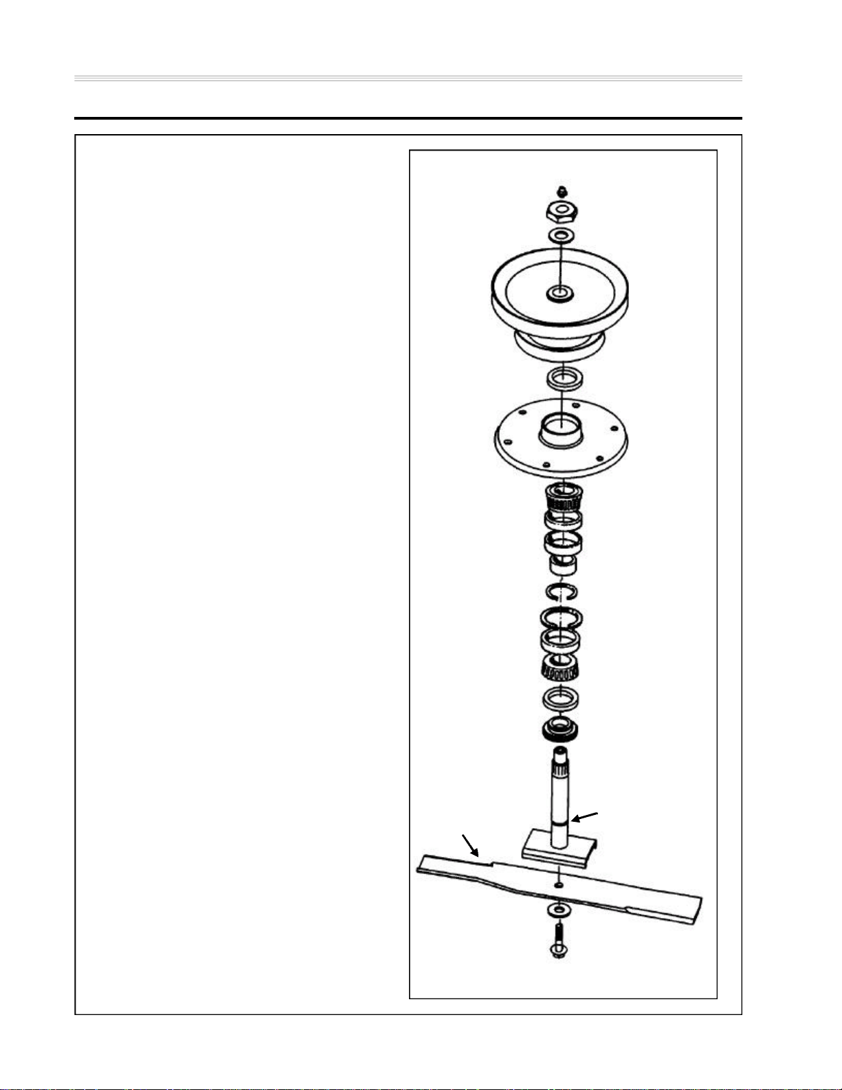
11. Remove the seals, note the direction of the
seals, this will be important during reassembly. The upper seal faces inward,
and the lower seal faces outward. If the
lower seal is installed incorrectly, the lower
bearing spacer will crush the seal and
allow dirt into the assembly, causing bearing failure to occur.
12. Remove the bearings and the two small
diameter spacers from the housing. One of
the two spacers removed will look like a
"C" slip and the other will be a thicker
spacer with a hole in it. The open side on
the “C” shaped spacer, in addition to the
lubrication hole in the thicker spacer,
allows grease to pass from the spindle
shaft to the bearings.
Note: When removing the bearings, mark or
isolate the top bearing from the lower
bearing. This will allow the bearings to
be installed in their original operating
position. Failure to do this may cause
premature bearing failure when
reassembled.
Spindle
Housing
Bearing Cone
Bearing Cup
Large Spacer
Small Spacer
Machine “C” Spacer
Snap Ring
Bearing Cup
Bearing Cone
Seal
Bearing Spacer
Spindle Shaft
Grease Axis Hole
Blade
Inspect the bearings as follows:
A. Look for the presence of grease, par-
ticularly in the upper bearing. Dry or
cooked grease indicates a lack of
maintenance
B. Look for dirt in the grease. This indi-
cates a bad seal or worn lower bearing spacer. If the unit was recently
4 Spindle Repair Module
Spring Washer
Blade Bolt
Page 5
Z Master 200 Series
rebuilt, look for proper installation of
the lower seal.
C. Clean the bearings and look for any
pitting or flaking on the rollers.
D. Roll the clean bearings in your hand
and feel for rough spots. If the bearing catches or the rollers get stuck in
the cage, replace the bearing.
Note: With this spindle design, both bearings
and bearing cups must be replaced as
a set. Even if only one of the two bearings is damaged.
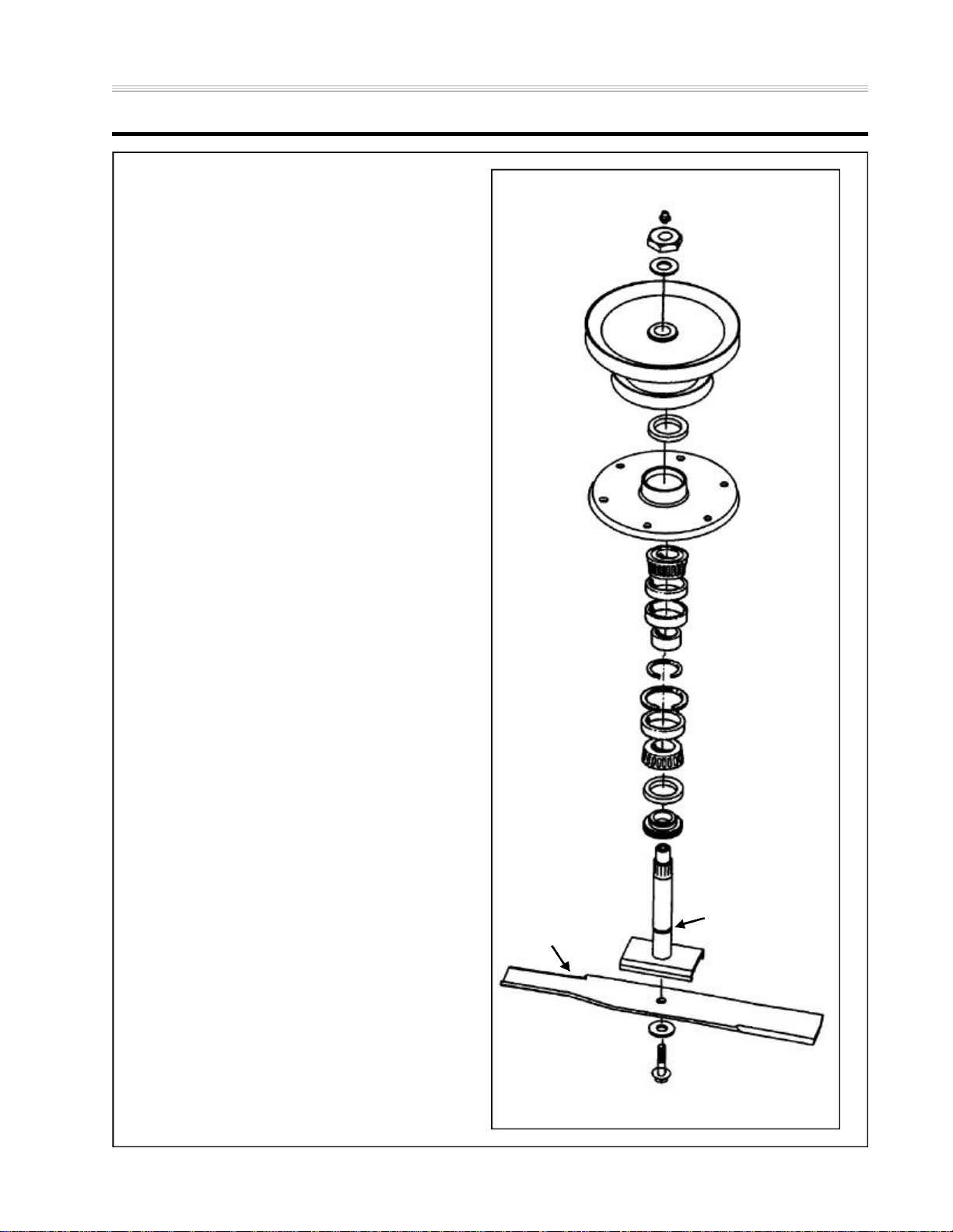
13. If replacing the bearings, use a punch and
hammer to drive both of the bearing cups
out of the spindle housing. Also, remove
the large diameter spacer at this time.
Caution: Do not use old bearing cups with
new bearings. This may cause premature bearing wear and result in
failure.
Zerk
Nut
Hardened Washer
Pulley
Seal
Spindle
Housing
Bearing Cone
Bearing Cup
14. A large snap ring is still inside the spindle
housing. It locates the matched bearing
set in the bore of the spindle housing.
There is no need to remove and replace
this snap ring.
Assembly
15. Thoroughly clean and inspect the parts
prior to assembly:
A. Spindle shaft for bearing surface
damage or signs of impact. Also
check for damage to the threaded
areas for both the blade bolt and the
pulley retention nut.
B. Bottom bearing spacer for wear. If
the spacer is damaged the seal may
not be able to keep dirt out properly.
C. Bearings for wear. If reusing bear-
ings, you must examine them carefully for wear. Also, make sure to put
the same bearing and bearing saddle
together as they were. As noted
above, look for pitting on the rollers
of the bearings and replace the bearing set if any pitting is present.
Large Spacer
Machine “C” Spacer
Bearing Cup
Seal
Spindle Shaft
Blade
Spring Washer
Small Spacer
Snap Ring
Bearing Cone
Bearing Spacer
Grease Axis Hole
Blade Bolt
5Spindle Repair Module
Page 6

Z Master 200 Series
Note: If using compressed air to dry the
bearing after cleaning, DO NOT allow
it to spin. The bearing could come
apart and cause serious injury. Always
wear safety glasses.
D. Spindle housing for damage or wear.
E. Pulley assembly, if the shaft shows
signs of wear inspect the pulley for
excessive wear in the splines. If
excessive wear is found, replace the
pulley. Excessive wear of the splines
will show up as sharp edges on the
splines.
Note: New bearings are only available in
matched sets. The matched set is
necessary because the bearing endplay is not adjustable. The small "C"
shaped spacer is machined to specifically match the bearings in the set.
The advantage of a matched set is the
ability to torque the assembly to a
specified value and have a pre-set
endplay. Alternatively, most tapered
bearing applications use either a crush
washer or a castle nut with key as a
means to set endplay.
16. Install the snap ring into spindle housing.
Discard the new snap ring if the spindle
housing is being reused.
17. Press in lower bearing cup until it firmly
contacts the snap ring.
Zerk
Nut
Hardened Washer
Pulley
Seal
Spindle
Housing
Bearing Cone
Bearing Cup
Large Spacer
Small Spacer
Machine “C” Spacer
Snap Ring
Bearing Cup
Bearing Cone
Seal
Bearing Spacer
Note: The machined stop for the seal may
cause your driver to stop before the
bearing cup is seated completely.
NEVER use a punch to drive in a bearing cup, this will damage the cup.
18. Slide the large spacer in from the top until
it also contacts the snap ring. Now press
the upper bearing cup in against the spacer. Apply a layer of grease to both bearing
surfaces.
19. Pack both bearings with grease. Smearing
grease on the outside of the bearing is not
6 Spindle Repair Module
Spindle Shaft
Blade
Spring Washer
Grease Axis Hole
Blade Bolt
Page 7

Z Master 200 Series
enough lubrication. Pack the bearing by
hand or use a bearing packing tool.
Zerk
20. With the spindle upside down, set the
lower bearing in the bearing cup. Now
install the lower seal. Use a seal driver to
prevent damage.
Note: Remember to install the seal with the
lip facing out.
21. With the spindle right side up, install the
small "C" shaped spacer first, then the
small thick spacer. The order of these two
is not critical to the performance of the
spindle, but putting the thinner spacer in
first it prevents the possibility of the open
part of the spacer from dropping down on
the thicker spacer.
22. Now install the upper bearing and seal.
The upper seal must face inward. Again,
be sure to use a seal driver.
23. Lubricate both seal lips with grease and
insert the bearing spacer into the lower
seal. By inserting the spacer individually,
and not with the shaft, you will prevent
possible damage to the lower seal.
24. Bolt the assembly back into the deck shell.
25. Install the spindle shaft.
Note: The shaft will slide out if not supported.
Nut
Hardened Washer
Pulley
Seal
Spindle
Housing
Bearing Cone
Bearing Cup
Large Spacer
Small Spacer
Machine “C” Spacer
Snap Ring
Bearing Cup
Bearing Cone
Seal
Bearing Spacer
26. Slide the pulley down onto the shaft and
secure with the washer and nut. Be certain
to only use the washer specified because
it is hardened, a softer washer will deform
and spindle damage will occur. Torque the
nut to 100-120 ft/lbs and rotate the assembly to make sure that it turns smoothly and
freely.
27. Pump grease into the assembly until
grease is relieved pass the lower seal.
The ability to relieve grease without pushing out the seal is why to lower seal is
installed with the lip facing out. Make sure
the blade bolt is threaded into the spindle
Spindle Shaft
Blade
Spring Washer
Grease Axis Hole
Blade Bolt
7Spindle Repair Module
Page 8

Z Master 200 Series
shaft or grease will push out that opening.
28. Install the blade and torque the blade bolt
to 85-110 ft/lbs.
29. Install the drive belts. Consult the machine
owner's manual for this procedure.
Zerk
Nut
Hardened Washer
30. Replace the deck covers.
31. Remove the machine from the jack
stands.
Pulley
Seal
Spindle
Housing
Bearing Cone
Bearing Cup
Large Spacer
Small Spacer
Machine “C” Spacer
Snap Ring
Bearing Cup
Bearing Cone
Seal
Bearing Spacer
Spindle Shaft
Blade
Spring Washer
8 Spindle Repair Module
Grease Axis Hole
Blade Bolt
Page 9

Z Master 500 Series
1. Stop the engine, remove the key, and
engage the parking brake.
2. Remove covers from the cutting unit.
3. Using a floor jack and properly rated jack
stands or the Z Stand®, raise the machine
until you can access the underside of the
cutting unit.
4. Inspect the assembly before removing it
from the mower. Look for the following:
Nut
Heavy Washer
Square Key
Pulley Hub
Bearing
Shield
Seal Spacer
A. Bent or damaged blade.
B. Missing or unused grease zerk.
C. String, wire, rope, etc. wrapped
around the spindle under the deck.
5. Remove the drive belt from the pulley.
Consult the machine operator's manual for
this procedure.
6. Remove the bolts retaining the spindle
pulley. Then remove the pulley from the
hub.
7. Unbolt the spindle housing from the deck.
Place spindle assembly on a bench or in a
vise and remove the blade.
8. Remove the spindle nut, heavy washer,
pulley hub, square key, and bearing
shield.
9. Inspect the pulley hub and square key for
damage. Carefully check the pulley hub
for cracks.
10. Remove the spindle shaft from the spindle
housing. If corrosion has bonded spacers
or bearings to the shaft, it may need to be
pressed out.
Seal
Spindle
Housing
Bearing Cone
Bearing Cup
Inner Spacer
Outer Spacer
Machine “C” Spacer
Snap Ring
Bearing Cup
Bearing Cone
Seal
Seal Spacer
Bearing
Shield
Note: The lower bearing spacer may remain
on the spindle shaft.
11. Inspect the spindle shaft. Check for the
following:
A. Worn or damaged keyway. Impacts
cause key and keyway damage.
Spindle
Shaft
9Spindle Repair Module
Page 10

Z Master 500 Series
B. Damaged Shaft - when the shaft is
worn at the point where the upper
bearing is located in the assembly, it
is a result of the assembly running
loose. The cause for this is improper
torque on the pulley hub retention
nut. This allows individual components of the assembly to move and
wear.
12. Remove the seals, note the direction the
seals face. This will be important during
re-assembly. The upper seal faces
inward, and the lower seal faces outward.
If the lower seal is installed incorrectly, the
lower bearing spacer will crush the seal
and allow dirt into the assembly causing
bearing failure to occur. This orientation of
the lower seal also allows grease to
bypass the seal, purging old grease from
the spindle when fresh grease is supplied.
Nut
Heavy Washer
Square Key
Pulley Hub
Bearing
Shield
Seal Spacer
Seal
Spindle
Housing
13. Remove the bearing cones and inner
spacers.
Note: There is a long spacer and then a
machined "C" spacer.
Note: When removing the bearings, tag or
isolate the top bearing from the lower
bearing. This will allow the bearings to
be installed in their original operating
position. Failure to do this may cause
premature bearing failure when
reassembled.
Inspect the bearings as follows:
A. Look for the presence of grease, par-
ticularly in the upper bearing. Dry or
cooked grease indicates a lack of
maintenance.
B. Look for dirt in the grease. This indi-
cates a bad seal or worn lower bearing spacer. If the unit was recently
rebuilt, look for proper installation of
the lower seal.
C. Clean the bearings and look for any
pitting or flaking on the rollers.
D. Roll the clean bearings in your hand
and feel for rough spots. If the bearing catches or the rollers get stuck in
Bearing Cone
Bearing Cup
Inner Spacer
Outer Spacer
Machine “C” Spacer
Snap Ring
Bearing Cup
Bearing Cone
Seal
Seal Spacer
Bearing
Shield
Spindle
Shaft
10 Spindle Repair Module
Page 11

Z Master 500 Series
the cage, replace the bearing set.
Note: With this spindle design, both bearings
and bearing cups must be replaced as
a set.
14. If replacing the bearings, use a punch and
hammer to drive both of the bearing cups
out of the spindle housing. Also remove
the large diameter spacer at this time if
spacers are to be replaced.
Caution: Do not use old bearing cups with
new bearings. This may cause premature bearing wear and result in
failure.
15. A large snap ring is still inside the spindle
housing. It locates the matched bearing
set in the spindle housing. Unless this is
damaged or worn, there is no need to
remove and replace this snap ring. A
replacement snap ring comes with the
replacement bearing set. If the snap ring is
damaged, look for damage to the housing.
Replace as needed.
Nut
Heavy Washer
Square Key
Pulley Hub
Bearing
Shield
Seal Spacer
Seal
Spindle
Housing
Bearing Cone
Bearing Cup
Inner Spacer
Assembly
16. Thoroughly clean and inspect the spindle
assembly parts prior to assembly. Always
wear safety glasses.
A. Check spindle shaft for bearing sur-
face damage or signs of impact. Also
check for damage to the threaded
areas for both the blade bolt and the
spindle retention nut.
B. Check lower bearing spacer for wear.
If the spacer is damaged, the seal
may not be able to keep dirt out
properly.
C. Check bearings for wear. If reusing
bearings, you must examine them
carefully for wear. Also, make sure to
put the same bearing cone and bearing cup together as they were when
disassembled. Look for pitting on the
rollers of the bearings and replace the
bearing set if any pitting is present.
Outer Spacer
Machine “C” Spacer
Snap Ring
Bearing Cup
Bearing Cone
Seal
Seal Spacer
Bearing
Shield
Spindle
Shaft
11Spindle Repair Module
Page 12

Z Master 500 Series
Note: If using compressed air to dry the
bearing after cleaning, DO NOT allow
it to spin. The bearing could come
apart and cause serious injury.
Note: New bearings are only available in
matched sets. The matched set is
necessary because the bearing endplay is not adjustable. The small "C"
shaped spacer is machined to specifically match the bearings in the set.
The advantage of a matched set is the
ability to torque the assembly to a
specified value and have a preset endplay.
D. Check spindle housing for any dam-
age or wear.
E. Check pulley hubs for wear marks or
worn keyway. A worn or cracked hub
should be replaced.
Nut
Heavy Washer
Square Key
Pulley Hub
Bearing
Shield
Seal Spacer
Seal
Spindle
Housing
17. If the snap ring is being replaced, install it
into the spindle housing. If the old snap
ring is being reused, discard the new snap
ring.
18. Press in lower bearing cup until it firmly
contacts the snap ring.
Note: The machined stop for the seal may
cause your driver to stop before the
bearing cup is seated completely.
NEVER use a punch to drive in a bearing cup. This will damage the cup.
19. Slide the large diameter spacer in from the
top until it also contacts the snap ring.
Now press the upper bearing cup in
against the spacer. Apply a layer of grease
to both bearing surfaces.
20. Pack both bearings with grease. Smearing
grease on the outside of the bearing is not
enough lubrication. Pack the bearing by
hand or use a bearing packing tool.
Bearing Cone
Bearing Cup
Inner Spacer
Outer Spacer
Machine “C” Spacer
Snap Ring
Bearing Cup
Bearing Cone
Seal
Seal Spacer
Bearing
Shield
Spindle
Shaft
21. With the spindle upside down, set the
lower bearing in the bearing cup. Now
install the lower seal. Use a seal driver to
prevent damage.
12 Spindle Repair Module
Page 13

Z Master 500 Series
Note: Remember to install the seal with the
lip facing out.
22. With the spindle right side up, install the
small "C" shaped spacer first, then the
long inner spacer. The order of these two
is not critical to the performance of the
spindle, but putting the thin spacer in first
prevents the possibility of the open part of
the spacer dropping down on the long
spacer.
23. Now install the upper bearing and seal.
The upper seal must face inward. Again,
use a seal driver.
24. Lubricate both seal lips with grease and
insert the bearing spacer into the lower
seal.
25. Place the bearing shield on the spindle
shaft with the cup up.
26. Slide the spindle shaft up through the
bearing spacer, lower bearing, spacers,
and upper bearing.
27. Install the upper bearing spacer on the
shaft and into the upper seal. By inserting
the upper spacer individually rather than
with the shaft, you will prevent possible
damage to the lower seal.
28. Place the bearing shield, cup down, on the
shaft.
29. Install the pulley hub, square key, heavy
cupped washer, and nut on the top of the
spindle. Torque the nut to 85-110 ft.-lbs.
30. Grease the spindle until grease flows from
the lower seal.
Nut
Heavy Washer
Square Key
Pulley Hub
Bearing
Shield
Seal Spacer
Seal
Spindle
Housing
Bearing Cone
Bearing Cup
Inner Spacer
Outer Spacer
Machine “C” Spacer
Snap Ring
Bearing Cup
Bearing Cone
Seal
Seal Spacer
Bearing
Shield
31. Bolt the assembly back into the deck shell.
The screws are self-tapping with a nut
backup on top of the deck. This design
makes it easier for one person alone to
install the spindle assembly and also provides a method of retention if a hole is
stripped out by overtorquing or repeated
replacement.
Spindle
Shaft
13Spindle Repair Module
Page 14

Z Master 500 Series
32. Install the pulley on the pulley hub and
torque the bolts to 27-33 ft.-lbs.
33. Install the blade and torque the blade bolt
to 85-110 ft.-lbs.
Nut
Heavy Washer
Square Key
34. Install the drive belt. Consult the operator's manual for the proper procedure.
35. Replace the deck covers. Remove the
machine from the jack stands or Z Stand®.
Pulley Hub
Bearing
Shield
Seal Spacer
Seal
Spindle
Housing
Bearing Cone
Bearing Cup
Inner Spacer
Outer Spacer
Machine “C” Spacer
Snap Ring
Bearing Cup
Bearing Cone
Seal
Seal Spacer
Bearing
Shield
Spindle
Shaft
14 Spindle Repair Module
Page 15

Page 16

492-4752
October 2003
 Loading...