

Toro 74179 Parts Catalogue

Form No. 3328–772
Z149
Z–Master with 52in Side Discharge Mower
Model No. 74179—220010043 and Up
Parts Catalog
Ordering Replacement Parts
To order replacement parts, please supply: the part
number, the quantity, and the description of each
part desired.
Understanding Reference Numbers
Each identified part in an illustration has a reference
number. The reference number for a part also appears in
the parts list, along with other information about the part.
This catalog uses two special reference number formats,
one to indicate parts in a service assembly and another
to indicate the quantity of a given part in an illustration.
Service Assembly Reference Numbers
Parts in service assemblies have reference numbers in
the form a:b.
the entire service assembly and the b represents a
sequential number unique to each part within the service
assembly.
The a represents the reference number of
The TORO Company — 2002
All Rights Reserved
For example, a wheel assembly might be identified by
reference number 6, the tire by 6:1, the valve by 6:2,
and the wheel by 6:3. When you order the assembly
identified by reference number 6, you receive all parts
identified by reference numbers 6:1, 6:2, and 6:3.
However, you may also order any part individually.
Reference numbers of this type appear in illustrations
and in part lists.
Reference Numbers Indicating Quantity
In an illustration, if a reference number indicates more
than one part, the reference number has the form nX y.
The n represents the quantity of the part, the X is the
multiplication symbol, and the y represents the reference
number.
For example, in an illustration, the reference number
2X 37 means that two of the parts identified by reference
number 37 are indicated.

3328–772
Contents
Description Page Description Page
Front Frame Assembly 4. . . . . . . . . . . . . . . . . . . . .
Height of Cut Assembly 6. . . . . . . . . . . . . . . . . . . .
Main Frame Assembly 7. . . . . . . . . . . . . . . . . . . . .
Fuel System Assembly 8. . . . . . . . . . . . . . . . . . . . .
Parking Brake System Assembly 9. . . . . . . . . . . .
Motion Control System Assembly 10. . . . . . . . . . . .
Hydraulic System Assembly 11. . . . . . . . . . . . . . . .
Pump, Idler and Belt Assembly 12. . . . . . . . . . . . . .
Engine and Clutch Assembly 13. . . . . . . . . . . . . . . .
Deck Assembly 14. . . . . . . . . . . . . . . . . . . . . . . . . . .
Deck Spindle Assembly 15. . . . . . . . . . . . . . . . . . . .
Idler, Pulley/Lift Strut, Chain Assembly 16. . . . . . .
Electrical System Assembly 17. . . . . . . . . . . . . . . . .
Electrical Schematic 18. . . . . . . . . . . . . . . . . . . . . . .
Piston/Crankshaft Assembly – Kawasaki
FH601V–AS23 19. . . . . . . . . . . . . . . . . . . . . . . . . .
Lubrication Equipment Assembly – Kawasaki
FH601V–AS23 20. . . . . . . . . . . . . . . . . . . . . . . . . .
Cylinder/Crankcase Assembly – Kawasaki
FH601V–AS23 21. . . . . . . . . . . . . . . . . . . . . . . . . .
Cylinder/Crankcase Assembly – Kawasaki
FH601V–AS23 22. . . . . . . . . . . . . . . . . . . . . . . . . .
Valve/Camshaft Assembly – Kawasaki
FH601V–AS23 23. . . . . . . . . . . . . . . . . . . . . . . . . .
Valve/Camshaft Assembly – Kawasaki
FH601V–AS23 24. . . . . . . . . . . . . . . . . . . . . . . . . .
Cooling Equipment Assembly – Kawasaki
FH601V–AS23 25. . . . . . . . . . . . . . . . . . . . . . . . . .
Cooling Equipment Assembly – Kawasaki
FH601V–AS23 26. . . . . . . . . . . . . . . . . . . . . . . . . .
Electric Equipment Assembly – Kawasaki
FH601V–AS23 27. . . . . . . . . . . . . . . . . . . . . . . . . .
Electric Equipment Assembly – Kawasaki
FH601V–AS23 28. . . . . . . . . . . . . . . . . . . . . . . . . .
Control Equipment Assembly – Kawasaki
FH601V–AS23 29. . . . . . . . . . . . . . . . . . . . . . . . . .
Control Equipment Assembly – Kawasaki
FH601V–AS23 30. . . . . . . . . . . . . . . . . . . . . . . . . .
Carburetor Assembly–Kawasaki FH601V–AS23 31
Carburetor Assembly–Kawasaki FH601V–AS23 32
Fuel Tank/Fuel Valve Assembly–Kawasaki
FH601V–AS23 33. . . . . . . . . . . . . . . . . . . . . . . . . .
Starter/Decal – Kawasaki FH601V–AS23 34. . . . .
Accessories
Description Model / Part No. Description Model / Part No.
Recycler Kit 59225. . . . . . . . . . . . . . . . . . . . . . . . . . . . . .
Bahaia Mulch Kit 59227. . . . . . . . . . . . . . . . . . . . . . . . . .
High Sail Blades
(3 required for improved bagging) 56–2390. . . . . .
Atomic Blades
(3 required for improved mulching) 104–1301. . . . .
Steel Bagger 30107. . . . . . . . . . . . . . . . . . . . . . . . . . . . . .
Striping Kit 30121. . . . . . . . . . . . . . . . . . . . . . . . . . . . . . .
High Suspension Seat 99–8522. . . . . . . . . . . . . . . . . .
Z–Stand Kit 105–1621. . . . . . . . . . . . . . . . . . . . . . . . . . .
Muffler Kit 105–3636. . . . . . . . . . . . . . . . . . . . . . . . . . . .
Hitch Kit 99–8924. . . . . . . . . . . . . . . . . . . . . . . . . . . . . . .
Roll–Over–Protection Kit 79470. . . . . . . . . . . . . . . . . . .
2

Part Description Abbreviations
Part descriptions in this catalog may include the following abbreviations.
Abbreviation Meaning Abbreviation Meaning
AR as required. . . . . . . . . . . . . . . . .
ASM assembly. . . . . . . . . . . . . . . .
CARR carriage. . . . . . . . . . . . . .
DEG degrees. . . . . . . . . . . . . . . .
FH flat head. . . . . . . . . . . . . . . . .
GA gauge. . . . . . . . . . . . . . . . .
HF hex flange. . . . . . . . . . . . . . . . .
HH hex head. . . . . . . . . . . . . . . . .
HHF hex head flange. . . . . . . . . . . . . . . .
HLH hex lag head. . . . . . . . . . . . . . . .
HJ hex jam. . . . . . . . . . . . . . . . . .
HOC height-of-cut. . . . . . . . . . . . . . . .
HS hex socket. . . . . . . . . . . . . . . . .
HSBH hex socket button head. . . . . . . . . . . . . .
HSFH hex socket flat head. . . . . . . . . . . . . . .
HSH hex socket head. . . . . . . . . . . . . . . .
HWH hex washer head. . . . . . . . . . . . . . .
HWHTF hex washer head. . . . . . . . . . . . .
thread forming
HYD hydraulic. . . . . . . . . . . . . . . .
INC incorporated. . . . . . . . . . . . . . . . .
LH left hand. . . . . . . . . . . . . . . . .
NI nylon insert. . . . . . . . . . . . . . . . . .
PPH Phillips pan head. . . . . . . . . . . . . . . .
PTH Phillips truss head. . . . . . . . . . . . . . . .
PTO power take off. . . . . . . . . . . . . . . .
RH right hand. . . . . . . . . . . . . . . . .
SFH slotted fillister head. . . . . . . . . . . . . . . .
SHH slotted hex head. . . . . . . . . . . . . . . .
SQH square head. . . . . . . . . . . . . . . .
SHWH slotted hex washer head. . . . . . . . . . . . . .
SPH slotted pan head. . . . . . . . . . . . . . . .
SRH slotted round head. . . . . . . . . . . . . . . .
STD standard. . . . . . . . . . . . . . . .
TAP self tapping. . . . . . . . . . . . . . . .
TTH Torx truss head. . . . . . . . . . . . . . . .
WH wing head. . . . . . . . . . . . . . . . .
3328–772
3
3328–772
9
11:3
8
7
6
5
38
10
11
11:2
12
14
15
16
17
18
22
13
13:4
14
13:3
13:2
15
21
9
19
20
23
24
22
25
5
4
3
36
18
21
1:6
1:2
1:3
1:2
1:3
1:4
1
1:5
1:1
1:7
1:1:1
1:1:2
1:1:3
1:4
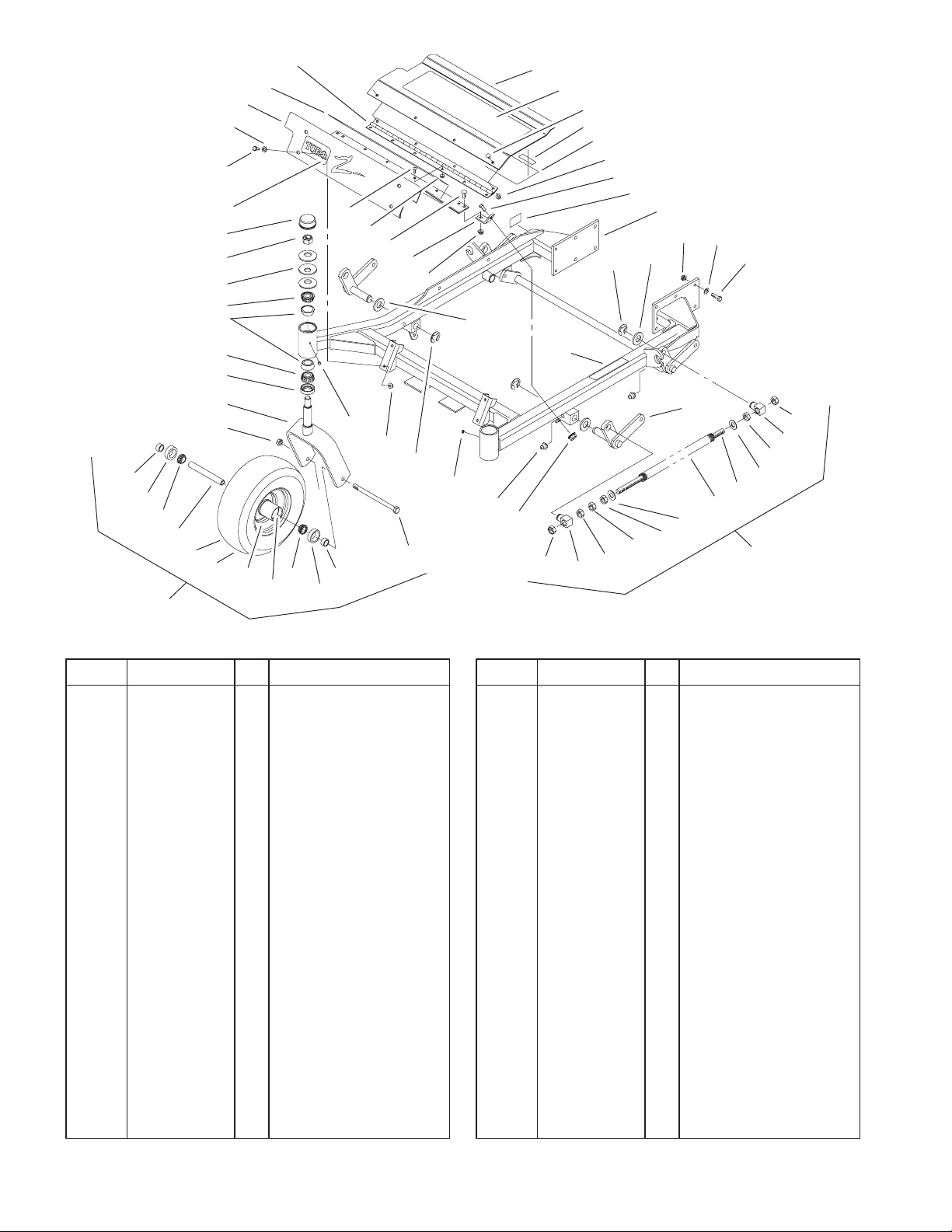
Front Frame Assembly
DescriptionPart No. Qty.Ref. No. DescriptionPart No. Qty.Ref. No.
1 1–634662 2 Caster Wheel ASM
1:1 1–633582 1 Wheel & Tire ASM
1:1:1 1–633002 1 Tire
1:1:2 1–633583 1 Wheel
1:1:3 1–633584 2 Bearing–Cup
1:2 1–633581 2 Spacer–Bearing
1:3 1–633580 2 Seal–Bearing
1:4 1–633585 2 Bearing–Cone, Taper
1:5 1–633579 1 Spacer–Caster, Front
1:6 325–36 1 Screw–HH
1:7 3296–45 1 Nut–Lock, NI
3 1–632511–01 2 Caster
4 1–543511 2 Seal–Grease
5 254–94 4 Bearing–Cone, Taper
6 1–633508 6 Washer–Bellville
7 3296–51 2 Nut–Lock, NI
8 1–543513 2 Cap–Grease
9 322–3 6 Screw–HH
10 3256–23 4 Washer–Flat
11 99–3940 1 Floorpan–Front
11:2 1–633553 1 Pad–Antiskid
11:3 1–633737 1 Decal–Z–Master
12 1–653049 1 Hinge–Floorpan
13 99–3930 1 Footrest ASM
13:2 99–3924 1 Decal–Service
13:3 98–5954 1 Decal–Missing, Cover
36
20:2
33 LH
34 RH
31:4
31:5
35
18
31:3
31:2
31:3
31:4
31:3
31:1
31:6
31:7
31
13:4 1–633553 1 Pad–Antiskid
14 3229–10 10 Screw–CARR
15 32128–33 10 Nut–HF
16 3230–1 2 Screw–CARR
17 99–3870–01 2 Bracket–Floorpan
18 32128–20 8 Nut–HF
19 105–2625 1 Decal–Safety STD
20 99–3931 1 Front Frame ASM
20:2 1–633818 1 Decal–Warning
21 32151–103 6 Ring–Snap
22 3256–29 6 Washer–Flat
23 3290–357 12 Nut–HHF
24 98–5975 12 Washer–Belleville
25 323–7 12 Screw–HH
31 103–1987 2 Front Spring ASM
31:1 1–653011 1 Rod–Lift, Deck
31:2 1–633441 2 Swivel–Deck Mount,
Rear
31:3 3217–11 4 Nut–Hex
31:4 3218–6 2 Nut–Jam
31:5 1–805517 1 Washer
31:6 1–653009 1 Spring–Compression
31:7 3256–27 1 Washer–Flat
33 99–3871–01 1 LH Lift Arm ASM
34 99–3872–01 1 RH Lift Arm ASM
35 302–19 4 Fitting–Grease
31:3
31:2
Sheet No.: 2
4
9
11:3
8
7
6
5
38
10
11
11:2
12
14
15
16
17
18
22
13
13:4
14
13:3
13:2
15
21
3328–772
9
19
20
23
24
22
25
5
4
3
36
18
21
1:6
1:2
1:3
1:2
1:3
1:4
1
1:5
1:1
1:7
1:1:1
1:1:2
1:1:3
1:4
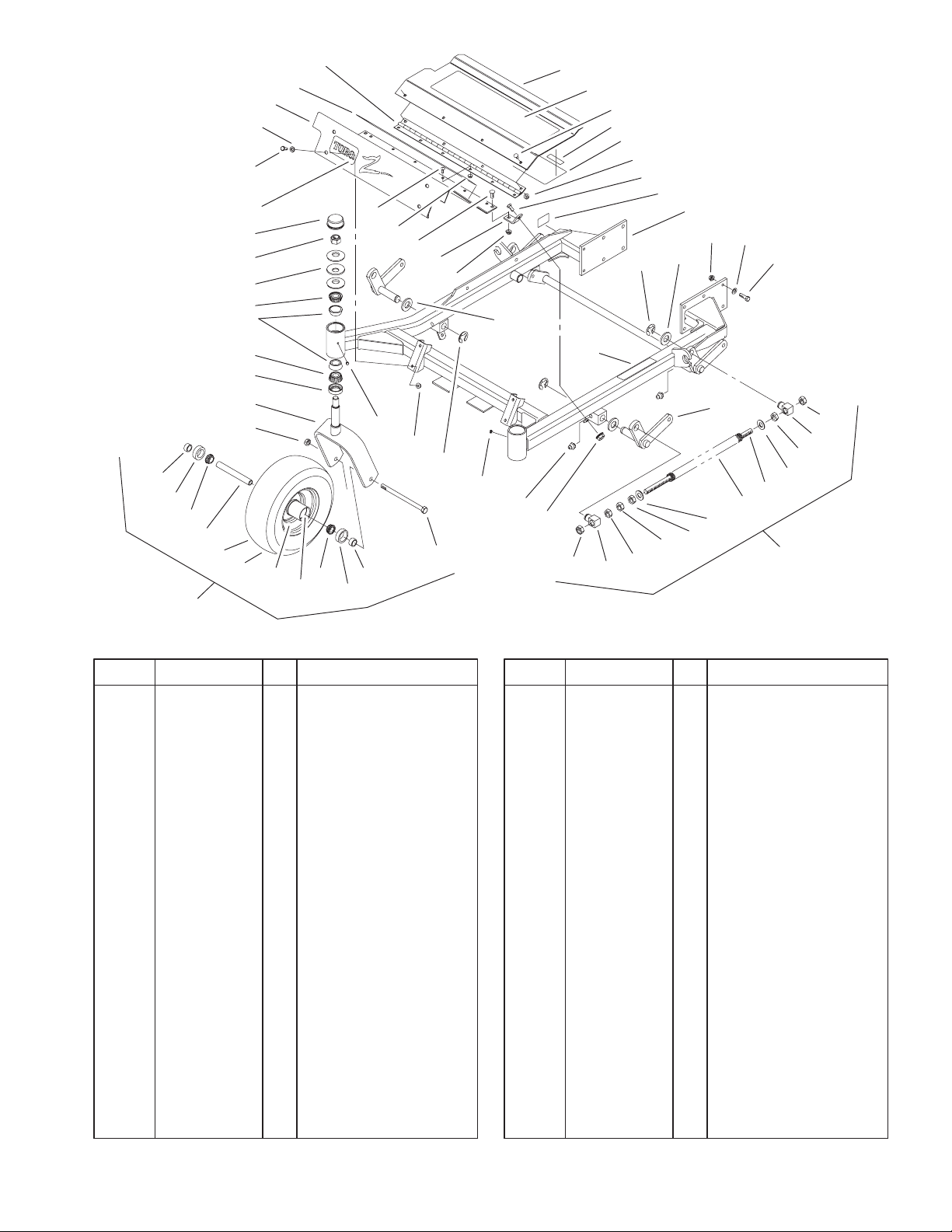
Front Frame Assembly (Continued)
DescriptionPart No. Qty.Ref. No. DescriptionPart No. Qty.Ref. No.
36 1–811010 2 Plug
38 254–72 4 Bearing–Cup, Tapered
36
35
18
20:2
31:3
31:2
31:3
31:4
31:3
33 LH
34 RH
31:6
31:7
31:3
31:2
31:4
31:5
31:1
31
Sheet No.: 2
5
3328–772
12
10
22
9
8
1
7
3
11
3
4
13
17
18
19
4
20
6
5
4
3
15
2
26
23
Height of Cut Assembly
DescriptionPart No. Qty.Ref. No. DescriptionPart No. Qty.Ref. No.
1 323–9 1 Screw–HH
2 32151–103 1 Ring–Snap
3 3290–357 3 Nut–HHF
4 3296–39 3 Nut–Lock, NI
5 1–652235–01 1 Plate–Lift, Deck
6 1–633080 1 Bushing–Lever, Lift
7 1–653230–01 1 Plate–Lift, Deck
8 1–806005 1 Pin–Hair
9 323–6 1 Screw–HH
10 323–13 1 Screw–HH
11 1–633082 1 Bushing–Lever, Lift
12 103–2078–03 1 Handle–Lift
13 1–633295 1 Grip–Lever, Lift
14 1–633097 1 Pin–Hitch W/Lanyard
15 302–19 1 Fitting–Grease
16 1–806003 2 Pin–Hair
17 99–3922–03 1 Arm–Lift
18 1–633325 1 Spring–Compression
19 3256–24 1 Washer–Flat
20 1–633068 2 Arm–Lift, Deck
21 1–808284 2 Pin–Clevis
22 1–653140 1 Decal–Deck Height
Outer
23 1–653147 1 Decal–Deck Height,
Inner
26 323–8 1 Screw–HH
16
21
14
3
Sheet No.: 3
6
17
18:6
18:5
10
18
18:1
18:2
3328–772
18:7
19
20
22
23
2:2
32
16
24
25
15
14
13
9
6
8
7
5
4
31
3
2:4
2:3
33
12
2
1
13:2
11
5
30
5
10
26
18:3 RH
18:4 LH
25:2
28
28:1
28:2
29
Sheet No.: 4
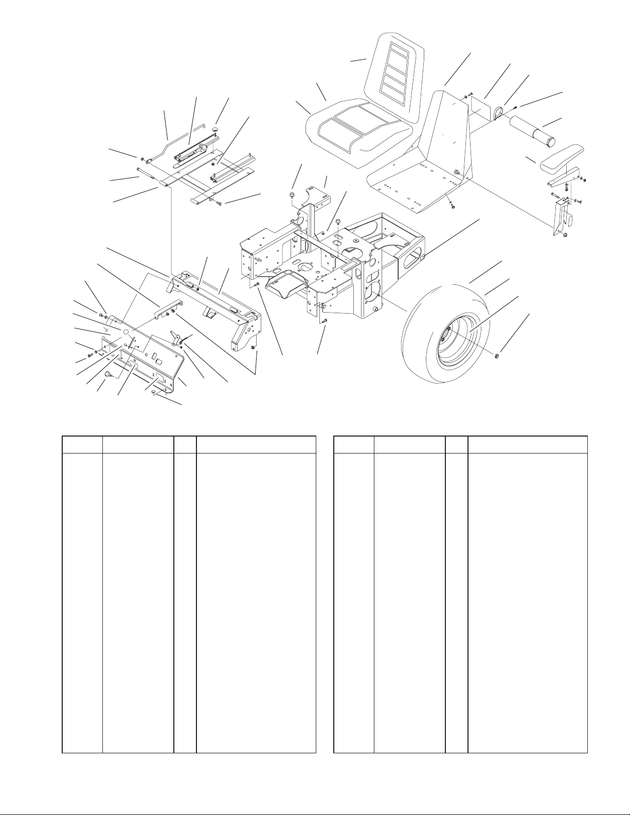
Main Frame Assembly
DescriptionPart No. Qty.Ref. No. DescriptionPart No. Qty.Ref. No.
1 1–513658 2 Bumper–Catcher,
Grass
2 99–3932 1 Control Panel ASM
2:2 99–3942 1 Decal–Panel, Control
2:3 103–0262 1 Decal–Valve, Fuel
2:4 98–4387 1 Decal–Protection, Ear
3 1–603336 1 Control–Choke
4 1–807513 2 Bolt–CARR
5 322–5 3 Screw–HH
6 3256–23 2 Washer–Flat
7 1–513592 1 Knob–Ball, Red
8 322–3 3 Screw–HH
9 1–653089–03 1 Bracket
10 32128–20 12 Nut–HF
11 1–633696 1 Cable–Throttle
12 3296–2 2 Nut–Lock
13 105–6123 1 Console ASM
13:2 103–1997 1 Decal–Top Console
14 1–632187–03 1 Frame–Seat
15 323–39 2 Screw–HH
16 3296–29 1 Nut–Lock, NI
17 103–1731 1 Rod–Retainer, Seat
18 1–633705 1 Seat W/Tracks
18:1 103–0290 1 Cushion–Bottom, Seat
18:2 104–7754 1 Cushion–Back, Seat
18:3 1–633710 1 Cushion–Armrest, RH
18:4 1–633711 1 Cushion–Armrest, LH
18:5 1–543401 4 Spacer–Track
18:6 1–643255 1 Grp–Track, Seat
18:7 1–633859 1 Frame–Seat
19 99–4693 1 Decal–Toro
20 2412–120 2 R–Clamp
22 32104–76 2 Screw
23 74–0720 1 Tube–Manual
24 1–523420 2 Bumper
25 105–6121 1 Main Frame ASM
25:2 65–2690 2 Decal–Surface, Hot
26 3296–42 2 Nut–Lock, NI
28 1–653159 2 ASM,Wheel & Tire
28:1 1–653160 1 Tire
28:2 1–653161 1 Wheel
29 242–50 8 Nut–Lug
30 322–2 6 Screw–HH
31 99–8909 1 Decal–Z149
32 3256–3 2 Washer–Flat
33 3296–39 2 Nut–Lock, NI
7
3328–772
7
20
12
10
11
16
7
10
9
7
20:3
1:2
2:2
21
3
22
23
1 LH
2 RH
3
4
5
Sheet No.: 5
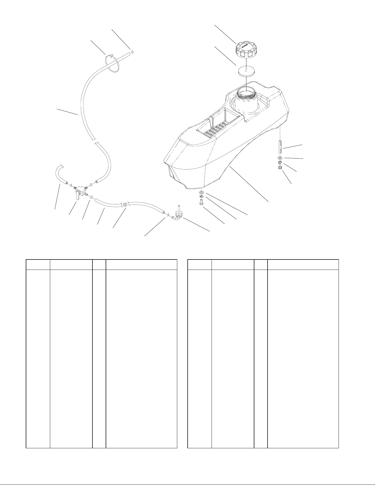
Fuel System Assembly
DescriptionPart No. Qty.Ref. No. DescriptionPart No. Qty.Ref. No.
1 105–3625 1 LH Fuel Tank ASM
1:2 103–2605 1 Fitting–Fuel, Bulkhead
2 105–3624 1 RH Fuel Tank ASM
2:2 103–2605 1 Fitting–Fuel, Bulkhead
3 3256–23 8 Washer–Flat
4 1–805005 4 Washer–Lock
5 322–3 4 Screw–HH
7 1–303077 6 Clamp–Line, Fuel
9 1–543296 2 Grommet–Line, Fuel
10 1–543526 2 Hose–Fuel
11 1–633347 1 Valve–Fuel
12 103–0216 1 Hose–Fuel
16 1–303335 1 Tie–Plastic
20 88–3980 2 Gas Cap ASM
20:3 88–4010 1 Gasket–Cap, Gas
21 1–633023 4 Stud
22 1–633349 4 Spring–Tank, Fuel
23 3296–47 4 Nut–Lock, NI
8
3328–772
1
2
2
3
4
29
35
27
4
5
6
21
19
20
19
24
31
17
34
15
10
14
16
7
34:2
9
11
11:1
11:2
34:1
13
33
Sheet No.: 6
30
3
28
5
26
25
22
21
18
5
3
4
5
2
36
27
28
21
23
32
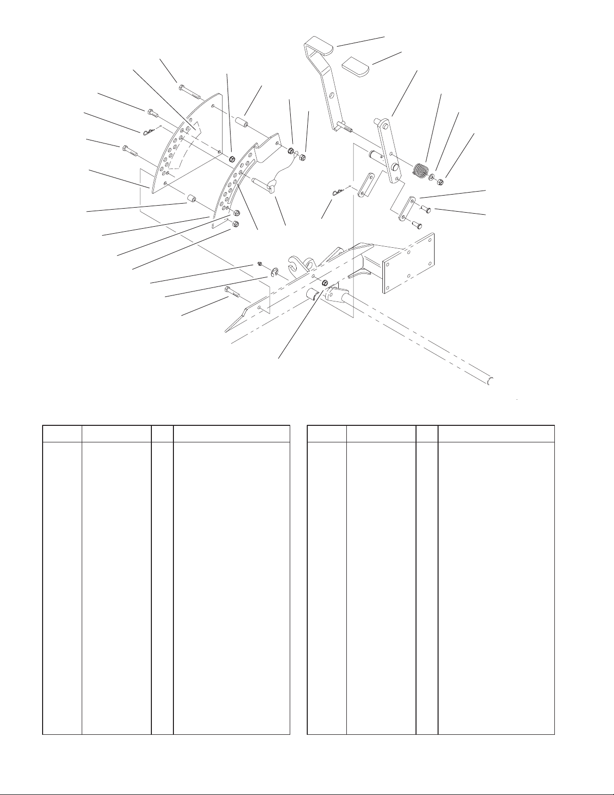
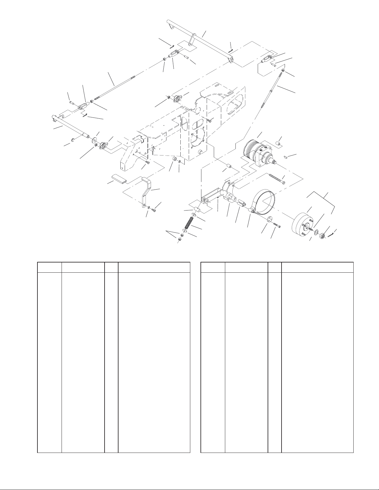
Parking Brake System Assembly
DescriptionPart No. Qty.Ref. No. DescriptionPart No. Qty.Ref. No.
1 1–652073–03 1 Crank–Brake, Park
2 3272–10 4 Pin–Cotter
3 1–633131 4 Yoke–Linkage, Brake
4 1–808285 4 Pin–Clevis
5 3219–3 8 Nut–HH
6 103–0356 2 Rod–Brake
7 1–653068 4 Spacer–Wheel
9 325–13 8 Screw–HH
10 103–0355 2 Band–Brake
11 103–0590 2 Hub–Wheel W/Studs
11:1 103–0589 1 Hub–Wheel
11:2 1–633926 4 Stud–Wheel
13 1–806800 2 Pin–Cotter
14 103–0374 2 Retainer–Band, Brake
15 103–0384 6 Spacer
16 322–9 6 Screw–HH
17 103–0352–03 2 Bracket–Brake
18 1–633144 2 Pin–Trunion
19 3256–4 4 Washer–Flat
20 1–633454 2 Spring–Brake
21 323–4 9 Screw–HH
22 1–653074–03 1 Handle–Brake, Park
23 1–633268 1 Grip–Lever, Brake
24 1–653069 4 Spacer–Wheel
25 3253–7 8 Washer–Lock
26 103–0131 8 Nut–Square
27 1–633102 4 Bearing–Flange, Side
28 3290–357 8 Nut–HHF
29 1–652085 1 Shaft–Brake, Parking
30 1–653061 1 Linkage–Handle,
Brake
31 1481 2 Fitting–Grease
32 98–5975 1 Washer–Belleville
33 1–523157 2 Washer–Spacer
34 1–523328 2 Motor–Wheel
34:1 1–809036 1 Nut–HH
34:2 3257–42 1 Key–Woodruff
*34:99 1–000099 1 Kit–Seal
*34:99 1–000139 1 Kit–Bearing
35 32151–48 1 E–Ring
36 3256–28 1 Washer–Flat
* Not illustrated
9
3328–772
27
26
25
24
23
28 RH
15 LH
16
7
14
13
12
17
11
28:1 RH
15:1 LH
18
9
30
19
21
20
9
9
7
22
11
13
40 39
9
1
3
2
4
58
31
32
33
9
36
16
37
16
38
Sheet No.: 7
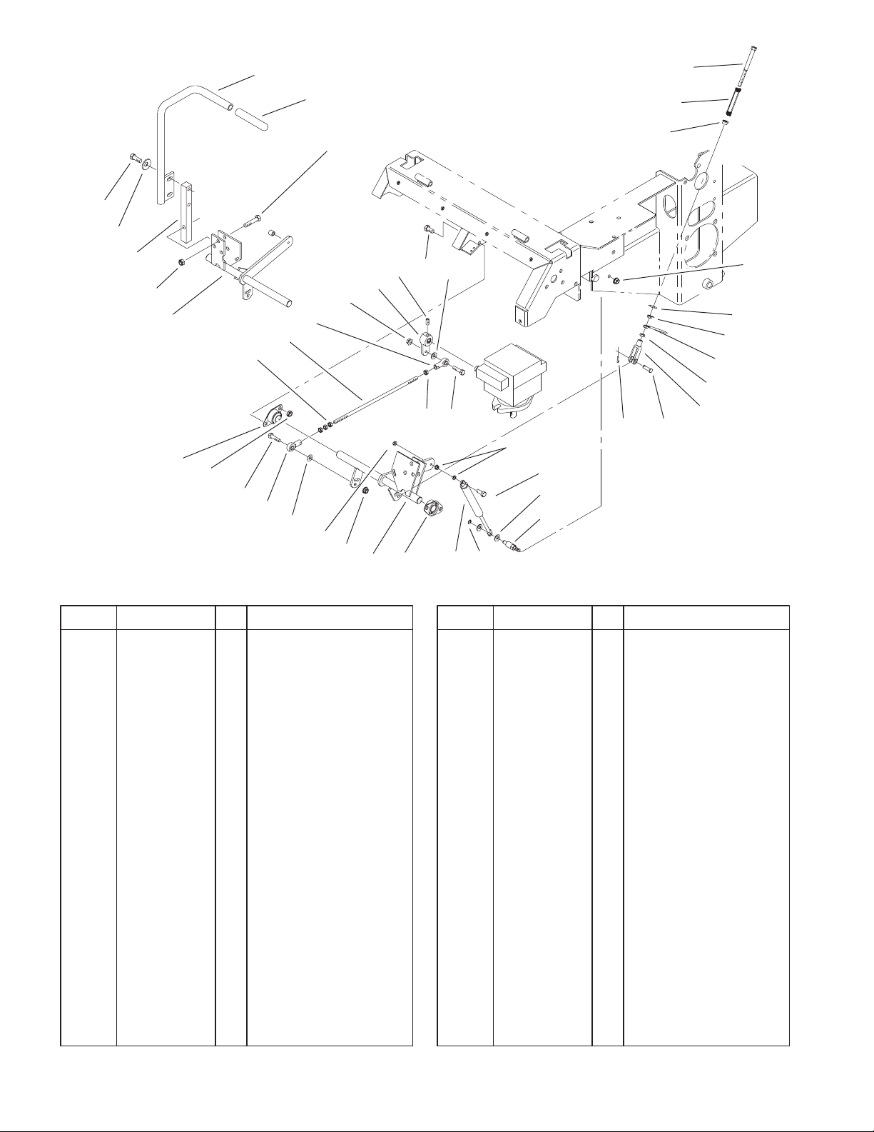
Motion Control System Assembly
DescriptionPart No. Qty.Ref. No. DescriptionPart No. Qty.Ref. No.
1 1–403180 2 Screw–HH
2 1–653316 2 Pin–Damper
3 3256–23 4 Washer–Flat
4 32120–35 2 E–Ring
5 1–523027 2 Damper–Control
7 1–633102 4 Bearing–Flange, Side
8 103–2199 1 LH Motion Control
ASM
9 32128–20 12 Nut–HF
11 3256–3 4 Washer–Flat
12 1–543017 2 Balljoint–RH
13 322–6 4 Screw–HH
14 3290–357 8 Nut–HHF
15 103–0631 1 LH Lever ASM
15:1 1–633257 1 Grip–Control, Motion
16 3219–2 10 Nut–Hex
17 1–653046 2 Linkage–Pump/Lever
18 1–633152 2 Balljoint–Thread, LH
19 323–4 8 Screw–HH
20 1–653092 2 Arm–Control, Pump
21 1–803022 2 Screw
22 1–804524 2 Nut
23 103–2200 1 RH Motion Control
ASM
24 3296–39 6 Nut–Lock, NI
25 103–0407 2 Arm–Shaft, Control
26 98–5975 4 Washer–Belleville
27 323–6 4 Screw–HH
28 103–0632 1 RH Lever ASM
28:1 1–633257 1 Grip–Control, Motion
30 323–9 6 Screw–HH
31 1–603737 2 Bolt–Return, Neutral
32 1–603807 2 Spring–Return,
Neutral
33 1–603735 2 Bushing–Flanged
36 3256–2 2 Washer–Flat
37 3220–2 2 Nut
38 1–303105 2 Yoke–Adjustable
39 1–808280 2 Pin–Clevis
40 3272–5 2 Pin–Cotter
10
18
18:2
16
11
10
8
16:1
3328–772
39
40:2
40
35
17:2
9
27
16:1
45
28
22:1
22
37
17
29
5
31
32
33
34
40:1
30
24:1:1
24:1:2
25
24
23:1
20
23
21
5
17
37
3
9
3:1
7
1
11
10
18:1
19
37
3
3:1
24:2
17
17:1
16
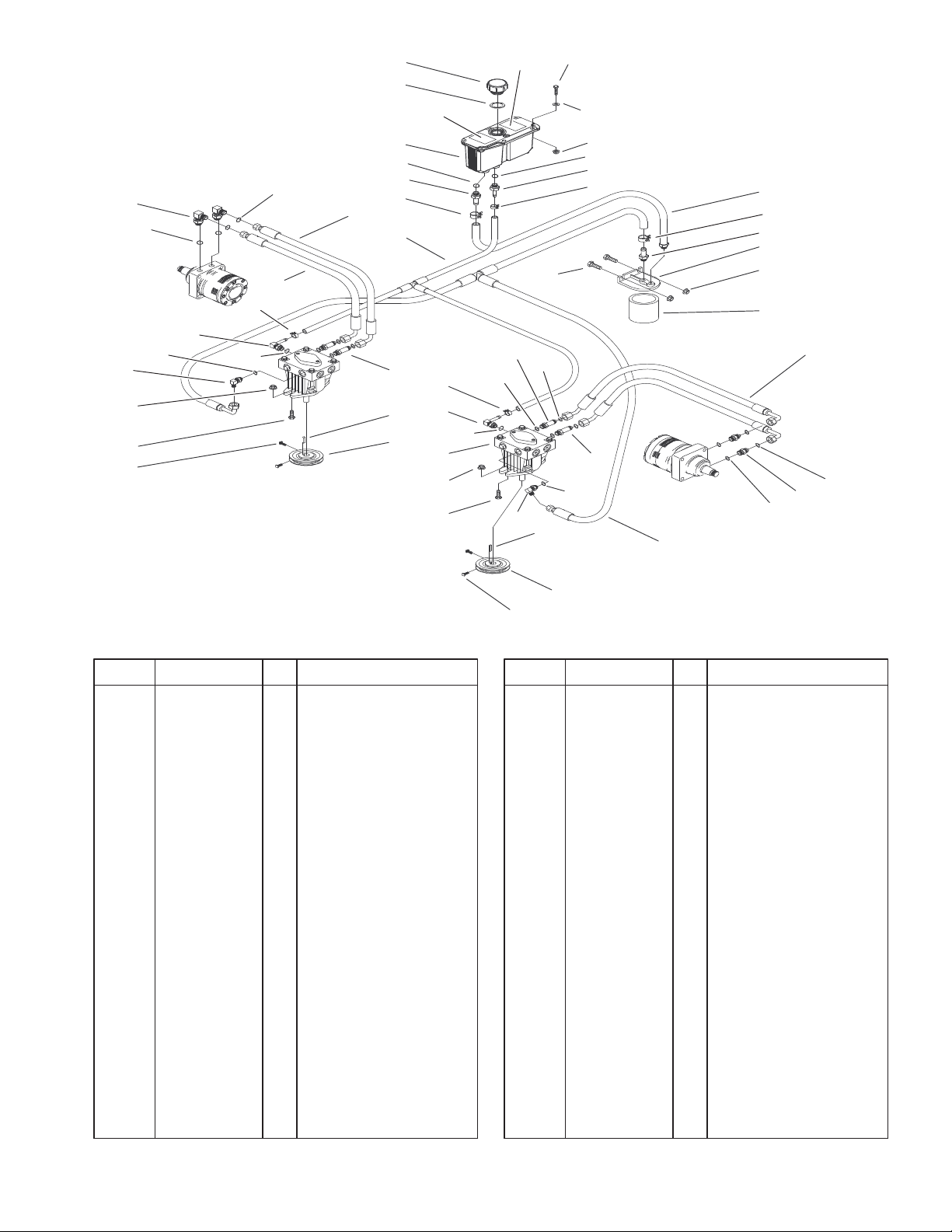
Hydraulic System Assembly
DescriptionPart No. Qty.Ref. No. DescriptionPart No. Qty.Ref. No.
1 103–1942 2 Pump–Hydraulic
*1:1 105–6184 1 Kit – Overhaul, Seal
*1:2 105–6185 1 Plate – Valve
*1:8 103–2664 1 Kit,Input Shaft 10a
*1:9 103–2665 1 Kit,Thrust Bearing 10a
*1:10 103–2666 1 Kit,Cylinder Block 10a
3 103–1799 2 Elbow–90
3:1 237–42 1 O–Ring
5 103–1988 2 Clamp–Hose
7 1–653156 2 Sheave
8 1–803050 4 Screw–Set
9 1–807272 2 Key–Machine
10 323–7 4 Screw–HH
11 3290–357 4 Nut–HHF
16 103–1802 2 Elbow–90
16:1 237–42 1 O–Ring
17 103–1940 4 Adapter,Straight
17:1 237–79 1 O–Ring
17:2 1–603992 1 O–Ring
18 1–633605 2 Fitting–Connector
18:1 1–603992 1 O–Ring
18:2 237–80 1 O–Ring
19 1–653186 1 Hose,Front
20 1–653187 1 Hose,RH Rear
21 103–1800 1 HYD Hose ASM
22 103–1801 1 Adapter–Straight
7
8
Sheet No.: 8
22:1 237–42 1 O–Ring
23 103–1912 1 Adapter,Straight
23:1 237–42 1 O–Ring
24 103–1947 1 HYD Reservoir ASM
24:1 1 HYD Reservoir ASM
24:1:1 103–1948 1 Cap–Hydraulic
Reservoir
24:1:2 103–1949 1 Gasket–Cap
24:2 1–523552 1 Decal–Tank, Hydraulic
25 103–2644 1 Decal–Exhaust
27 321–14 2 Screw–HH
28 32128–33 2 Nut–HF
29 103–1805 1 HYD Hose ASM
30 103–1803 1 HYD Hose ASM
31 103–1804 1 Adapter–Straight
32 1–603720 1 Head–Filter
33 32128–20 2 Nut–HF
34 1–633750 1 Filter–HYD
34 1–633752 1 Filter–HYD, Winter
35 322–5 2 Screw–HH
37 103–1716 3 Clamp–Hose
39 103–1680 2 Hose–LH
40 1–603991 2 Fitting–Straight
40:1 237–80 1 O–Ring
40:2 1–603992 1 O–Ring
45 3256–22 2 Washer–Flat
* Not illustrated
Not serviced separately
11
 Loading...