

Page 1

Form No. 3329–863
Z149 and Z153
Z Master with 52in SFS Side Discharge Mower
Model No. 74163—Serial No. 240000001 and Up
Model No. 74167—Serial No. 240000001 and Up
Operator ’s Manual
Register your product at www.Toro.com
Original Instructions (EN)
Page 2

Warning
CALIFORNIA
Proposition 65 Warning
The engine exhaust from this product contains
chemicals known to the State of California to cause
cancer, birth defects, or other reproductive harm.
Important This engine is not equipped with a spark
arrester muffler. It is a violation of California Public
Resource Code Section 4442 to use or operate this engine
on any forest–covered, brush–covered or grass–covered
land. Other states or federal areas may have similar laws.
This spark ignition system complies with Canadian
ICES-002.
Ce système d’allumage par étincelle de véhicule est
conforme à la norme NMB-002 du Canada.
The enclosed Engine Owner’s Manual is supplied for
information regarding The U.S. Environmental
Protection Agency (EPA) and the California Emission
Control Regulation of emission systems, maintenance
and warranty.
Keep this engine Owner’s Manual with your unit.
Should this engine Owner’s Manual become damaged
or illegible, replace immediately. Replacements may be
ordered through the engine manufacturer.
Contents
Page
Introduction 3. . . . . . . . . . . . . . . . . . . . . . . . . . . . . . . .
Safety 3. . . . . . . . . . . . . . . . . . . . . . . . . . . . . . . . . . . . .
Safe Operating Practices 3. . . . . . . . . . . . . . . . . . . .
Slope Chart 7. . . . . . . . . . . . . . . . . . . . . . . . . . . . . .
Safety and Instruction Decals 9. . . . . . . . . . . . . . . .
Gasoline and Oil 14. . . . . . . . . . . . . . . . . . . . . . . . . . . . .
Recommended Gasoline 14. . . . . . . . . . . . . . . . . . . .
Using Stabilizer/Conditioner 14. . . . . . . . . . . . . . . .
Filling the Fuel Tank 14. . . . . . . . . . . . . . . . . . . . . .
Checking the Engine Oil Level 14. . . . . . . . . . . . . .
Operation 15. . . . . . . . . . . . . . . . . . . . . . . . . . . . . . . . . .
Using the Rollover Protection System (ROPS) 15. .
Think Safety First 16. . . . . . . . . . . . . . . . . . . . . . . . .
Controls 17. . . . . . . . . . . . . . . . . . . . . . . . . . . . . . . .
Operating the Parking Brake 17. . . . . . . . . . . . . . . .
Starting and Stopping the Engine 18. . . . . . . . . . . . .
Operating the Power Take Off (PTO) 19. . . . . . . . . .
The Safety Interlock System 19. . . . . . . . . . . . . . . .
Page
Driving Forward or Backward 20. . . . . . . . . . . . . . .
Stopping the Machine 20. . . . . . . . . . . . . . . . . . . . . .
Adjusting the Height-of-Cut 21. . . . . . . . . . . . . . . . .
Adjusting the Anti-Scalp Rollers 21. . . . . . . . . . . . .
Positioning the Seat 22. . . . . . . . . . . . . . . . . . . . . . .
Pushing the Machine by Hand 22. . . . . . . . . . . . . . .
Operating with Side Discharge 22. . . . . . . . . . . . . . .
Transporting the Machine 23. . . . . . . . . . . . . . . . . . .
Loading Machines 23. . . . . . . . . . . . . . . . . . . . . . . .
Tips for Mowing Grass 24. . . . . . . . . . . . . . . . . . . . .
Maintenance 25. . . . . . . . . . . . . . . . . . . . . . . . . . . . . . . .
Recommended Maintenance Schedule 25. . . . . . . . .
Servicing the Cutting Blades 26. . . . . . . . . . . . . . . .
Cleaning the Cooling System 28. . . . . . . . . . . . . . . .
Servicing the Air Cleaner 28. . . . . . . . . . . . . . . . . . .
Servicing the Engine Oil 29. . . . . . . . . . . . . . . . . . .
Servicing the Spark Plug 31. . . . . . . . . . . . . . . . . . .
Replacing the Fuel Filter 31. . . . . . . . . . . . . . . . . . .
Draining the Fuel Tank 32. . . . . . . . . . . . . . . . . . . . .
Greasing and Lubrication 32. . . . . . . . . . . . . . . . . . .
Checking the Tire Pressure 33. . . . . . . . . . . . . . . . . .
Servicing the Hydraulic System 34. . . . . . . . . . . . . .
Adjusting the Handle Neutral Position 36. . . . . . . . .
Setting the Hydraulic Pump Neutral Position 37. . . .
Adjusting the Tracking 38. . . . . . . . . . . . . . . . . . . . .
Adjusting the Caster Pivot Bearing 38. . . . . . . . . . .
Checking the Wheel Hub Slotted Nut 39. . . . . . . . .
Leveling the Mower at Three Positions 39. . . . . . . .
Adjusting the Push Arms 41. . . . . . . . . . . . . . . . . . .
Cleaning Under the Mower 41. . . . . . . . . . . . . . . . .
Inspecting the Belts 41. . . . . . . . . . . . . . . . . . . . . . .
Replacing the Mower Belt 41. . . . . . . . . . . . . . . . . .
Replacing the Pump Drive Belt 42. . . . . . . . . . . . . .
Adjusting the Parking Brake 43. . . . . . . . . . . . . . . .
Servicing the Fuses 43. . . . . . . . . . . . . . . . . . . . . . . .
Servicing the Battery 44. . . . . . . . . . . . . . . . . . . . . .
Replacing the Grass Deflector 46. . . . . . . . . . . . . . .
Waste Disposal 47. . . . . . . . . . . . . . . . . . . . . . . . . . .
Mercury Tilt Switch 47. . . . . . . . . . . . . . . . . . . . . . .
Mercury Tilt Switch Disposal 47. . . . . . . . . . . . . . . .
Wiring Diagram 48. . . . . . . . . . . . . . . . . . . . . . . . . .
Cleaning and Storage 49. . . . . . . . . . . . . . . . . . . . . .
Troubleshooting 50. . . . . . . . . . . . . . . . . . . . . . . . . . . . .
The Toro Total Coverage Guarantee 52. . . . . . . . . . . . .
2003 by The Toro Company
8111 Lyndale Avenue South
Bloomington, MN 55420-1196
Contact us at www.Toro.com
All Rights Reserved
2
Printed in the USA
Page 3
Introduction
Safety
Read this manual carefully to learn how to operate and
maintain your product properly. The information in this
manual can help you and others avoid injury and product
damage. Although Toro designs and produces safe
products, you are responsible for operating the product
properly and safely.
Whenever you need service, genuine Toro parts, or
additional information, contact an Authorized Service
Dealer or Toro Customer Service and have the model and
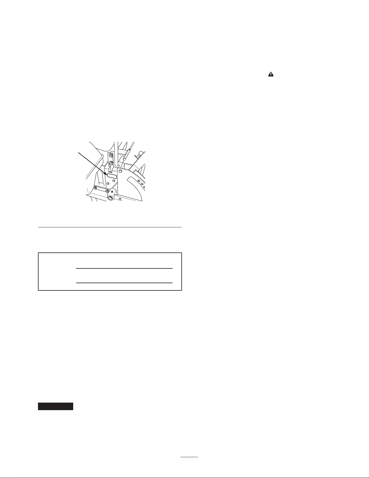
serial numbers of your product ready. Figure 1 illustrates
the location of the model and serial numbers on the
product.
1
m–3648
Figure 1
1. Location of the model and serial numbers
Write the product model and serial numbers in the space
below:
Model No.
Serial No.
This manual identifies potential hazards and has special
safety messages that help you and others avoid personal
injury and even death. Danger, Warning, and Caution are
signal words used to identify the level of hazard. However,
regardless of the hazard, be extremely careful.
Improper use or maintenance by the operator or owner
can result in injury. To reduce the potential for injury,
comply with these safety instructions and always pay
attention to the safety alert symbol, which means
CAUTION, WARNING, or DANGER—“personal
safety instruction.” Failure to comply with the
instruction may result in personal injury or death.
This product is capable of amputating hands and feet and
throwing objects. Always follow all safety instructions to
avoid serious injury or death.
This product is designed for cutting and recycling grass or,
when equipped with a grass bagger, for catching cut grass.
Any use for purposes other than these could prove
dangerous to user and bystanders.
Safe Operating Practices
The following instructions are from ANSI standard
B71.4—1999.
Training
• Read the Operator’s Manual and other training material.
If the operator(s) or mechanic(s) can not read English it
is the owner’s responsibility to explain this material to
them.
• Become familiar with the safe operation of the
equipment, operator controls, and safety signs.
• All operators and mechanics should be trained. The
owner is responsible for training the users.
• Never let children or untrained people operate or
service the equipment. Local regulations may restrict
the age of the operator.
• The owner/user can prevent and is responsible for
accidents or injuries occurring to himself or herself,
other people or property.
Danger signals an extreme hazard that will cause serious
injury or death if you do not follow the recommended
precautions.
Warning signals a hazard that may cause serious injury or
death if you do not follow the recommended precautions.
Caution signals a hazard that may cause minor or moderate
injury if you do not follow the recommended precautions.
This manual uses two other words to highlight information.
Important calls attention to special mechanical
information and Note: emphasizes general information
worthy of special attention.
Preparation
• Evaluate the terrain to determine what accessories and
attachments are needed to properly and safely perform
the job. Only use accessories and attachments approved
by the manufacturer.
• Wear appropriate clothing including hard hat, safety
glasses and hearing protection. Long hair, loose
clothing or jewelry may get tangled in moving parts.
• Inspect the area where the equipment is to be used and
remove all objects such as rocks, toys and wire which
can be thrown by the machine.
3
Page 4

• Use extra care when handling gasoline and other fuels.
They are flammable and vapors are explosive.
• Use only an approved container
• Never remove gas cap or add fuel with engine
running. Allow engine to cool before refueling.
Do not smoke.
• Never refuel or drain the machine indoors.
• Check that operator’s presence controls, safety switches
and shields are attached and functioning properly. Do
not operate unless they are functioning properly.
• Use care when approaching blind corners, shrubs, trees,
or other objects that may obscure vision.
Slope Operation
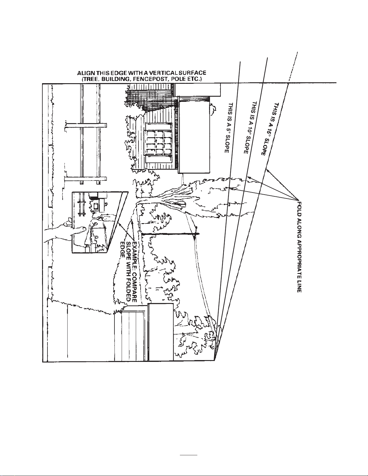
• Do not mow slopes greater than 15 degrees.
• Do not mow near drop–offs, ditches, steep banks or
water. Wheels dropping over edges can cause rollovers,
which may result in serious injury, death or drowning.
• Do not mow slopes when grass is wet. Slippery
conditions reduce traction and could cause sliding and
loss of control.
Operation
• Never run an engine in an enclosed area.
• Only operate in good light, keeping away from holes
and hidden hazards.
• Be sure all drives are in neutral and parking brake is
engaged before starting engine. Start the engine only
from the operator’s position.
• Never raise deck with the blades running.
• Never operate without the PTO shield, or other guards
securely in place. Be sure all interlocks are functioning
properly.
• Never operate with the discharge deflector raised,
removed or altered, unless using a grass catcher.
• Do not change the engine governor setting or overspeed
the engine.
• Stop on level ground, lower implements, disengage
drives, engage parking brake, shut off engine before
leaving the operator’s position for any reason including
emptying the catchers or unclogging the chute.
• Stop equipment and inspect blades after striking objects
or if an abnormal vibration occurs. Make necessary
repairs before resuming operations.
• Keep hands and feet away from the cutting units.
• Never carry passengers and keep pets and bystanders
away.
• Be alert, slow down and use caution when making
turns. Look behind and to the side before changing
directions.
• Slow down and use caution when crossing roads and
sidewalks. Stop blades if not mowing.
• Be aware of the mower discharge direction and do not
point it at anyone.
• Do not operate the mower under the influence of
alcohol or drugs.
• Use extreme care when loading or unloading the
machine into a trailer or truck.
• Do not make sudden turns or rapid speed changes.
• Use a walk behind mower and/or a hand trimmer near
drop–offs, ditches, steep banks or water.
• Reduce speed and use extreme caution on slopes.
• Remove or mark obstacles such as rocks, tree limbs,
etc. from the mowing area. Tall grass can hide
obstacles.
• Watch for ditches, holes, rocks, dips, and rises that
change the operating angle, as rough terrain could
overturn the machine.
• Avoid sudden starts when mowing uphill because the
mower may tip backwards.
• Be aware that loss of traction may occur going
downhill. Weight transfer to the front wheels may cause
drive wheels to slip and cause loss of braking and
steering.
• Always avoid sudden starting or stopping on a slope. If
tires lose traction, disengage the blades and proceed
slowly off the slope.
• Follow the manufacturer’s recommendations for wheel
weights or counterweights to improve stability.
• Use extreme care with grass catchers or other
attachments. These can change the stability of the
machine and cause loss of control.
Using the Rollover Protection System
(ROPS)
• Keep the roll bar in the raised and locked position and
use the seat belt when operating the machine.
• Be certain that the seat belt can be released quickly in
the event of an emergency.
• Be aware there is no rollover protection when the roll
bar is down.
• Check the area to be mowed and never fold the ROPS
in areas where there are slopes, drop offs or water.
4
Page 5

• Lower the rollbar only when absolutely necessary. Do
not wear the seat belt with the roll bar folded down.
• Check carefully for overhead clearances (i.e. branches,
doorways, electrical wires) before driving under any
objects and do not contact them.
Maintenance and storage
• Disengage drives, lower implement, set parking brake,
stop engine and remove key or disconnect spark plug
wire. Wait for all movement to stop before adjusting,
cleaning or repairing.
• Clean grass and debris from cutting units, drives,
mufflers, and engine to help prevent fires. Clean up oil
or fuel spillage.
• Let engine cool before storing and do not store near
flame.
• Shut off fuel while storing or transporting. Do not store
fuel near flames or drain indoors.
• Park machine on level ground. Never allow untrained
personnel to service machine.
• Use jack stands to support components when required.
• Carefully release pressure from components with stored
energy.
• Disconnect battery or remove spark plug wire before
making any repairs. Disconnect the negative terminal
first and the positive last. Reconnect positive first and
negative last.
• Use care when checking blades. Wrap the blade(s) or
wear gloves, and use caution when servicing them.
Only replace blades. Never straighten or weld them.
• Keep hands and feet away from moving parts. If
possible, do not make adjustments with the engine
running.
• Charge batteries in an open well ventilated area, away
from spark and flames. Unplug charger before
connecting or disconnecting from battery. Wear
protective clothing and use insulated tools.
• Keep all parts in good working condition and all
hardware tightened. Replace all worn or damaged
decals.
• Use only Toro-approved attachments. Warranty may be
voided if used with unapproved attachments.
5
Page 6

6
Page 7
Slope Chart
7
Page 8

8
Page 9
Safety and Instruction Decals
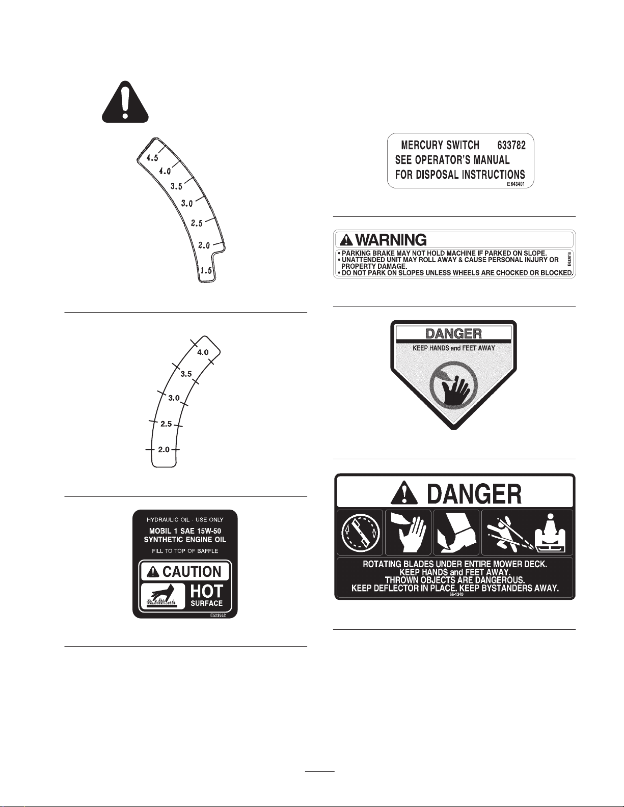
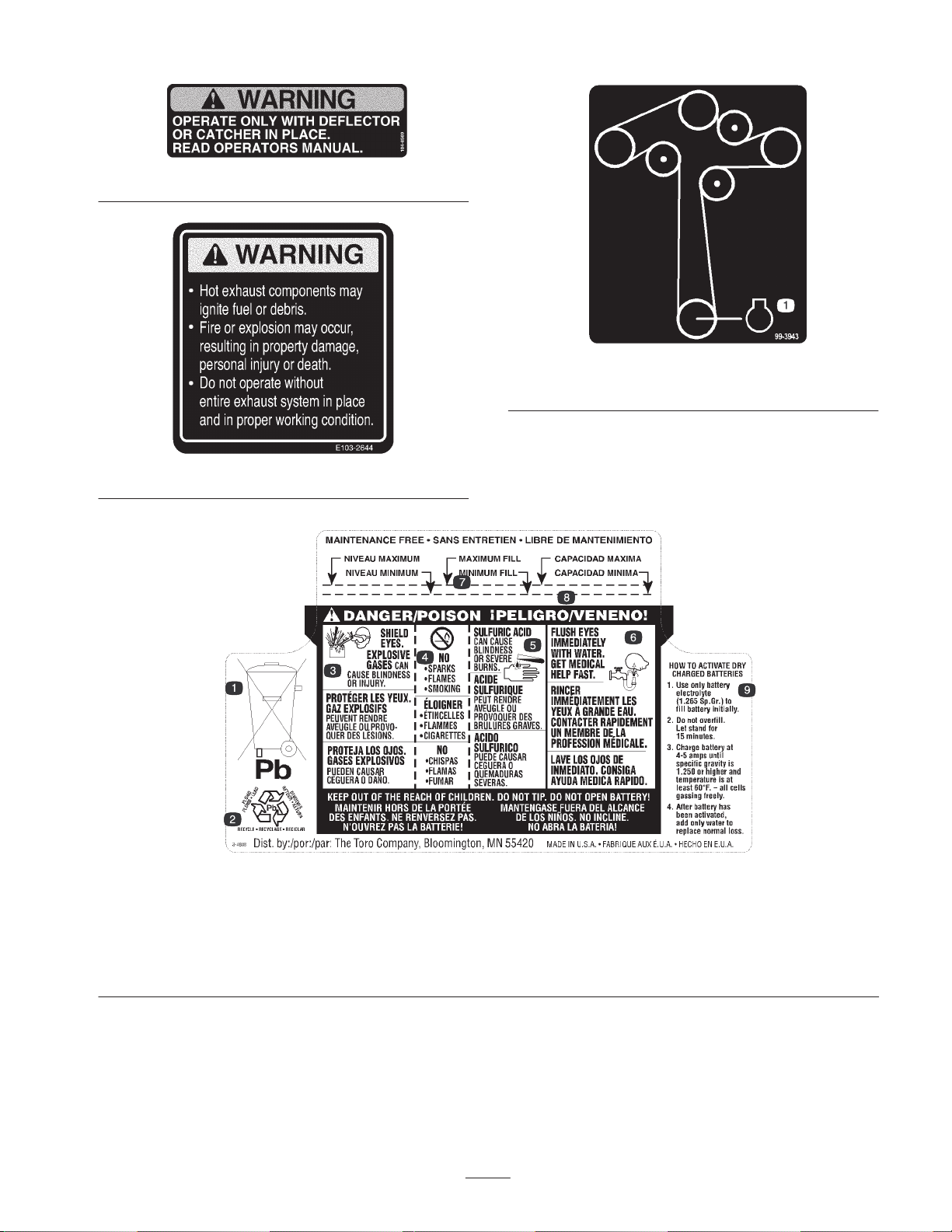
Safety decals and instructions are easily visible to the operator and are located near any area
of potential danger. Replace any decal that is damaged or lost.
1-643401
1–653140
1–653147
1-633818
43-8480
1-523552
66-1340
9
Page 10

67-5360
93-1122
65–2690
98-4387
1. Warning—wear hearing protection.
98-5954
93-7818
1. Warning—read the
torquing the blade bolt/nut to 115–149 N⋅m (85–110 ft-lb).
Operator’s Manual
for instructions on
98-3798
1. Explosion hazard
2. No fire, open flames, or
smoking.
3. Caustic liquid/chemical
burn hazard
103–0262
104-4163
4. Wear eye protection
5. Read the
6. Keep bystanders a safe
Manual.
Operator’s
distance from the battery.
10
Page 11
104-8569
103–2644
99-3943
1. Engine
1. Contains lead; do not
discard.
2. Recycle
3. Wear eye protection;
explosive gases can cause
blindness and other injuries
4. No sparks, flame, or
smoking
5. Sulfuric acid can cause
blindness or severe burns.
104-4164
6. Flush eyes immediately with
water and get medical help
fast.
7. Maximum fill line
11
8. Minimum fill line
9. Instructions for activating the
battery
Page 12
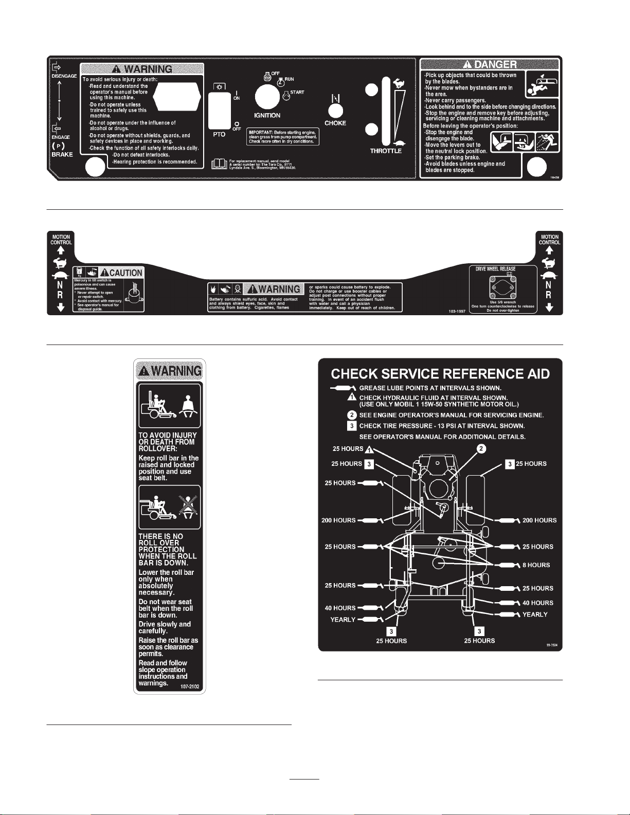
106-6586
103-1997
107-2102
99-3924
12
Page 13

107-2112
13
Page 14

Gasoline and Oil
Recommended Gasoline
Use UNLEADED Regular Gasoline suitable for automotive
use (85 pump octane minimum). Leaded regular gasoline
may be used if unleaded regular is not available.
Important Never use methanol, gasoline containing
methanol, or gasohol containing more than 10% ethanol
because the fuel system could be damaged. Do not mix oil
with gasoline.
Danger
In certain conditions, gasoline is extremely
flammable and highly explosive. A fire or
explosion from gasoline can burn you and others
and can damage property.
• Fill the fuel tank outdoors, in an open area,
when the engine is cold. Wipe up any gasoline
that spills.
• Never fill the fuel tank inside an enclosed trailer.
• Do not fill the fuel tank completely full. Add
gasoline to the fuel tank until the level is 1/4 to
1/2 inch (6 to 13 mm) below the bottom of the
filler neck. This empty space in the tank allows
gasoline to expand.
• Never smoke when handling gasoline, and stay
away from an open flame or where gasoline
fumes may be ignited by a spark.
• Store gasoline in an approved container and
keep it out of the reach of children. Never buy
more than a 30-day supply of gasoline.
• Always place gasoline containers on the ground
away from your vehicle before filling.
• Do not fill gasoline containers inside a vehicle or
on a truck or trailer bed because interior
carpets or plastic truck bed liners may insulate
the container and slow the loss of any static
charge.
• When practical, remove gas–powered
equipment from the truck or trailer and refuel
the equipment with its wheels on the ground.
• If this is not possible, then refuel such
equipment on a truck or trailer from a portable
container, rather than from a gasoline dispenser
nozzle.
• If a gasoline dispenser nozzle must be used, keep
the nozzle in contact with the rim of the fuel
tank or container opening at all times until
fueling is complete.
• Do not operate without entire exhaust system in
place and in proper working condition.
Warning
Gasoline is harmful or fatal if swallowed.
Long-term exposure to vapors can cause serious
injury and illness.
• Avoid prolonged breathing of vapors.
• Keep face away from nozzle and gas tank or
conditioner opening.
• Keep gas away from eyes and skin.
Using Stabilizer/Conditioner
Use a fuel stabilizer/conditioner in the machine to provide
the following benefits:
• Keeps gasoline fresh during storage of 90 days or less.
For longer storage it is recommended that the fuel tank
be drained.
• Cleans the engine while it runs
• Eliminates gum-like varnish buildup in the fuel system,
which causes hard starting
Important Do not use fuel additives containing
methanol or ethanol.
Add the correct amount of gas stabilizer/conditioner to the
gas.
Note: A fuel stabilizer/conditioner is most effective when
mixed with fresh gasoline. To minimize the chance of
varnish deposits in the fuel system, use fuel stabilizer at all
times.
Filling the Fuel Tank
1. Shut the engine off and set the parking brake.
2. Clean around each fuel tank cap and remove the cap.
Add unleaded regular gasoline to both fuel tanks, until
the level is 1/4 to 1/2 inch (6 to 13 mm) below the
bottom of the filler neck. This space in the tank allows
gasoline to expand. Do not fill the fuel tanks completely
full.
3. Install fuel tank caps securely. Wipe up any gasoline
that may have spilled.
Checking the Engine Oil Level
Before you start the engine and use the machine, check the
oil level in the engine crankcase; refer to Checking the
Engine Oil Level, page 29.
14
Page 15
Operation
Note: Determine the left and right sides of the machine
from the normal operating position.
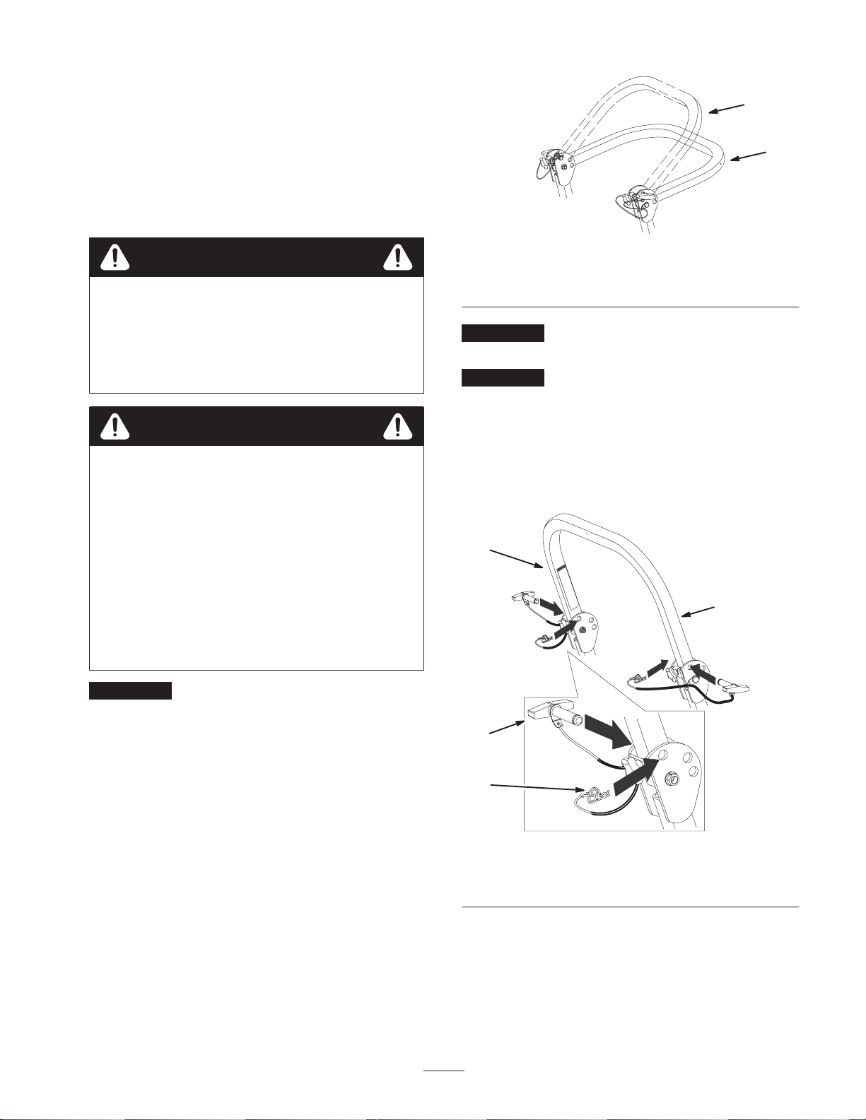
Using the Rollover Protection
2
1
System (ROPS)
Warning
To avoid injury or death from rollover: keep the
roll bar in the raised locked position and use the
seat belt.
Ensure that the rear part of the seat is secured
with the seat latch.
Warning
There is no rollover protection when the roll bar is
in the down position.
• Lower the roll bar only when absolutely
necessary.
• Do not wear the seat belt when the roll bar is in
the down position.
• Drive slowly and carefully.
• Raise the roll bar as soon as clearance permits.
• Check carefully for overhead clearances (i.e.
branches, doorways, electrical wires) before
driving under any objects and do not contact
them.
m–6836
Figure 2
1. Full down position 2. Down position with
bagger installed
Important Always use the seat belt with the roll bar in
the raised position.
Important Ensure that the rear part of the seat is
secured with the seat latch.
5. To raise the roll bar, remove the hairpin cotter pins and
remove the two pins (Fig. 3).
6. Raise the roll bar to the upright position and install the
two pins and secure them with the hairpin cotter pins
(Fig. 3).
1
2
Important Lower the roll bar only when absolutely
necessary.
1. To lower the roll bar, loosen the front handles (Fig. 4).
2. Remove the hairpin cotter pins and remove the two pins
(Fig. 3).
3. Lower the the roll bar to the down position. There are
two down positions. See Figure 2 for the positions.
4. Install the two pins and secure them with the hairpin
cotter pins (Fig. 3).
3
4
1. Roll bar
2. Raised position
15
m–6893
Figure 3
3. Pin
4. Hairpin cotter pin
Page 16
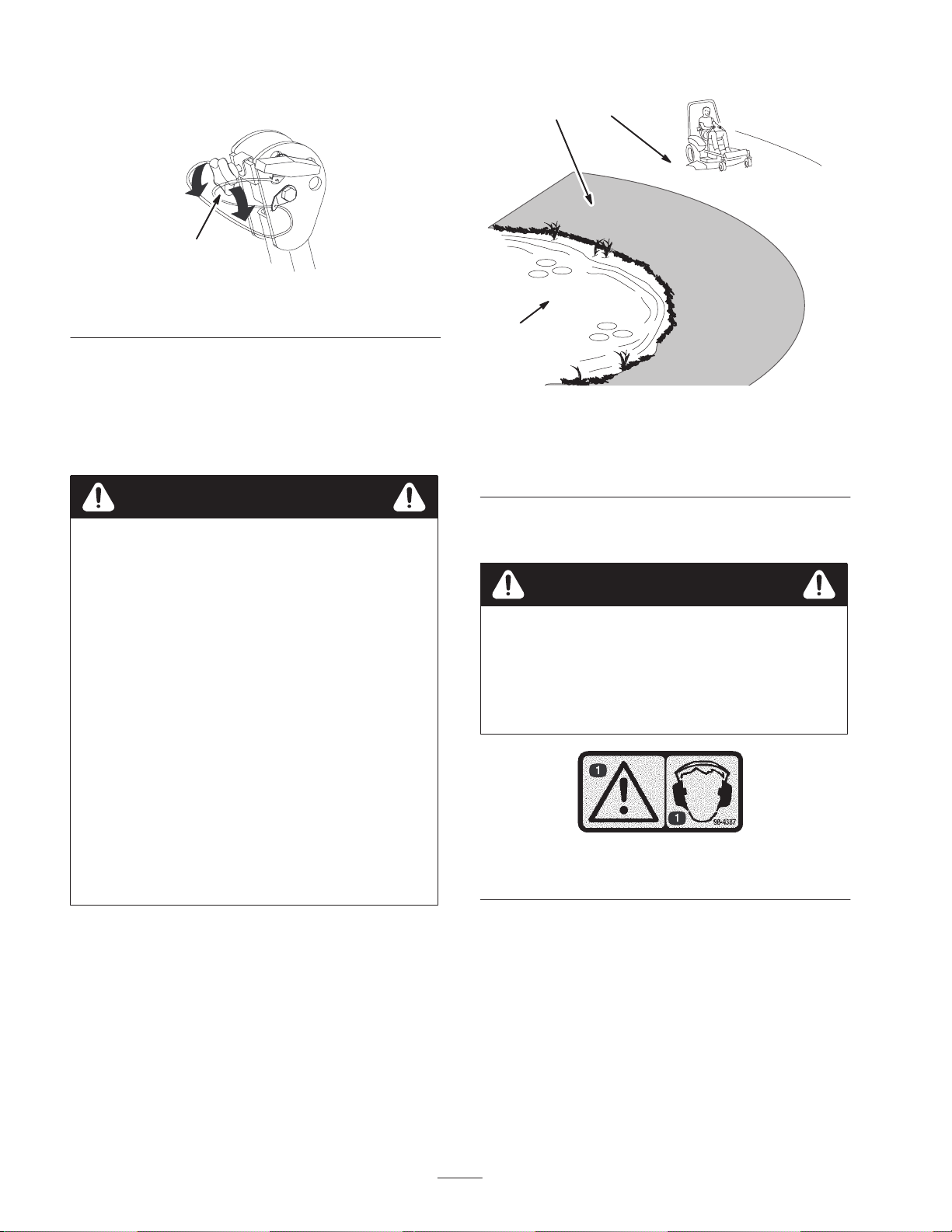
7. Tighten the front handles against the center roll bar ends
(Fig. 3).
2
1
1
m–6897
Figure 4
1. Front handle
Think Safety First
Please read all safety instructions and symbols in the safety
section. Knowing this information could help you or
bystanders avoid injury.
Danger
Operating on wet grass or steep slopes can cause
sliding and loss of control.
Wheels dropping over edges can cause rollovers,
which may result in serious injury, death or
drowning.
There is no rollover protection when the roll bar is
down.
Always keep the roll bar in the raised and locked
position and use the seat belt.
3
m–6478
Figure 5
1. Safe Zone—use the
Z Master here on slopes
less than 15 degrees or
flat areas.
2. Use walk behind mower
and/or hand trimmer near
drop–offs and water.
3. Water
The use of protective equipment for eyes, ears, feet, and
head is recommended.
Caution
This machine produces sound levels in excess of
85 dBA at the operators ear and can cause hearing
loss through extended periods of exposure.
Wear hearing protection when operating this
machine.
Read and follow the rollover protection
instructions and warnings.
To avoid loss of control and possibility of rollover:
• Do not operate near drop–offs or near water.
• Do not operate on slopes greater than
15 degrees.
• Reduce speed and use extreme caution on slopes.
• Avoid sudden turns or rapid speed changes.
Figure 6
1. Warning—wear hearing protection.
16
Page 17
Controls
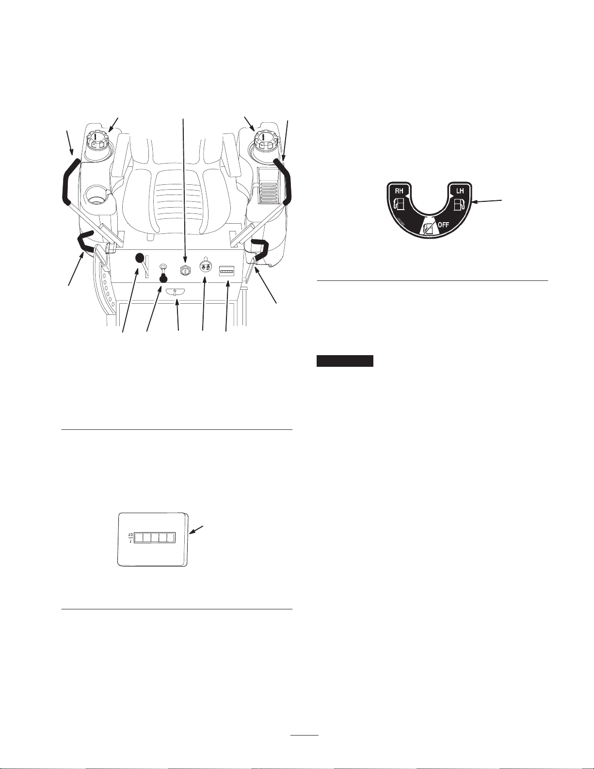
Become familiar with all the controls (Fig. 7) before you
start the engine and operate the machine.
8
2
7
1
8
The unit has two fuel tanks. One tank is on the left side and
one on the right side. Each tank connects to the fuel shut off
valve in the control panel. From there a common fuel line
leads to the engine (Fig. 9).
2
To use the left side fuel tank rotate the fuel shut off valve to
the LH, lefthand location. To use the right side fuel tank
rotate the fuel shut off valve to the RH, righthand location
(Fig. 9).
Close fuel shut off valve before transporting or storing
machine.
1
Figure 9
1. Shut-off valve
3
5
49
10
6
m–4200
Figure 7
1. Ignition switch
2. Motion control lever
3. Parking brake lever
4. Throttle
5. Choke
6. Power take off (PTO)
7. Height-of-cut lever
8. Fuel cap
9. Hourmeter
10. Fuel shut-off valve
Using the Hour Meter
The hour meter records the number of hours the engine has
operated. It operates when the engine is running. Use these
times for scheduling regular maintenance.
1
m–4202
Figure 8
1. Hour meter
Operating the Parking Brake
Always set the parking brake when you stop the machine or
leave it unattended.
Important Do not park on slopes unless the wheels are
chocked or blocked.
Setting the Parking Brake
1. Move the motion control levers (Fig. 10) out to the
neutral lock position.
2. Pull back and up on the parking brake lever to set the
parking brake (Fig. 10). The parking brake lever should
stay firmly in the Engaged position.
Releasing the Parking Brake
Push forward and down on the parking brake lever to
release the parking brake (Fig. 10). The parking brake is
disengaged.
Switching the Fuel Tanks
The fuel shut off valve is located under the seat.
17
Page 18
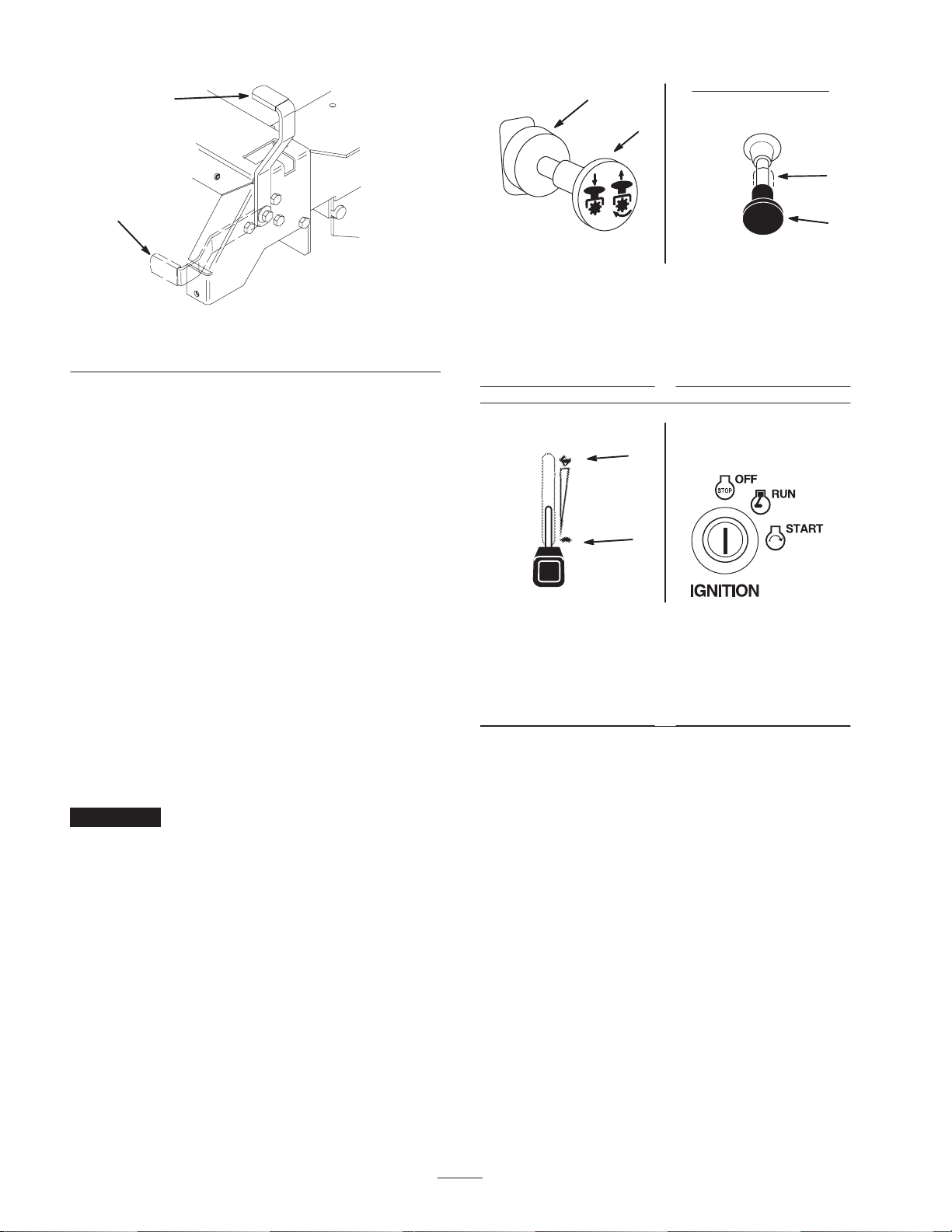
1
2
1
2
2
m–4121
Figure 10
1. Parking brake—On 2. Parking brake—Off
Starting and Stopping the
Engine
Starting the Engine
1. Sit down on the seat and move the motion controls to
the neutral locked position.
2. Set the parking brake; refer to Setting the Parking
Brake, page 17.
3. Move the PTO (power take off) to Off (Fig. 11).
4. Move the choke control to the On position before
starting a cold engine (Fig. 12).
Note: A warm or hot engine may require choking. After the
engine starts, move the choke control to the Off position.
5. Move the throttle control to the Fast position before
starting a cold engine (Fig. 13).
Figure 11
1. PTO—On
2. PTO—Off
Figure 13
1. Fast
2. Slow
m–4201
m–2720
1
m–2719
Figure 12
1. Choke—On
2. Choke—Off
1
1
2
3
2
M–4268
Figure 14
1. Off
2. Run
3. Start
6. Turn the ignition key to Start to energize the starter.
When the engine starts, release the key (Fig. 14).
Important Do not engage the starter for more than
10 seconds at a time. If the engine fails to start, allow a
30 second cool-down period between attempts. Failure to
follow these instructions can burn out the starter motor.
7. After the engine starts, move the choke to Off (Fig. 12).
If the engine stalls or hesitates, move the choke back to
On for a few seconds. Then move the throttle lever to
the desired setting. Repeat this as required.
Stopping the Engine
1. Push the PTO to off (Fig. 13).
2. Move the throttle lever midway between the slow and
fast positions (Fig. 13).
3. Let the engine idle for 60 seconds (Fig. 14).
4. Turn the ignition key to off (Fig. 14).
5. Pull wire off spark plug(s) to prevent possibility of
someone accidentally starting the machine before
transporting or storing machine.
6. Close fuel shut off valve, on front panel before
transporting or storing machine.
18
Page 19
Important Make sure that the fuel shut off valve is
closed before transporting or storing the machine, as fuel
leakage may occur. Set the parking brake before
transporting. Make sure to remove the key as the fuel pump
may run and cause the battery to lose charge.
Caution
Children or bystanders may be injured if they
move or attempt to operate the tractor while it is
unattended.
Always remove the ignition key and set the
parking brake when leaving the machine
unattended, even if just for a few minutes.
Operating the Power Take Off
(PTO)
The Safety Interlock System
Caution
If safety interlock switches are disconnected or
damaged the machine could operate unexpectedly
causing personal injury.
• Do not tamper with the interlock switches.
• Check the operation of the interlock switches
daily and replace any damaged switches before
operating the machine.
Understanding the Safety Interlock
System
The safety interlock system is designed to prevent the
engine from starting unless:
• You are sitting on the seat.
The power take off (PTO) switch engages and disengages
power to the electric clutch.
Engaging the PTO
1. While seated in the seat, release the pressure on the
traction control levers and place in neutral.
2. Place the throttle into the fast position.
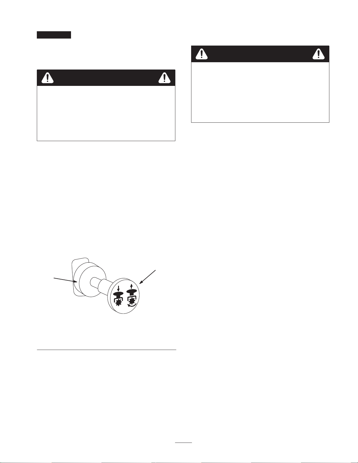
3. Pull out on the power take off (PTO) switch to engage
(Fig. 15).
2
1
m–4201
Figure 15
1. PTO—Off 2. PTO—On
• The parking brake is engaged.
• The power take off (PTO) is disengaged.
• The motion control levers are in the neutral lock
position.
The safety interlock system also is designed to stop the
engine when the traction controls are moved with the
parking brake on engaged or if you rise from the seat when
the PTO is on or engaged.
Testing the Safety Interlock System
Test the safety interlock system before you use the machine
each time. If the safety system does not operate as
described below, have an Authorized Service Dealer repair
the safety system immediately.
1. Sitting on the seat, engage the parking brake, and move
the PTO On. Try starting the engine; the engine should
not crank.
2. Sitting on the seat, engage the parking brake, and move
the PTO to Off. Move either motion control lever
(forward or reverse). Try starting the engine; the engine
should not crank. Repeat for the other motion control
lever.
Disengaging the PTO
To disengage, push the PTO switch to the Off position
(Fig. 15).
3. Sitting on the seat, engage the parking brake, move the
PTO to Off, and lock the motion control levers in
neutral. Now start the engine. While the engine is
running, release the parking brake, engage the PTO and
rise slightly from the seat; the engine should stop.
4. Sitting on the seat, engage the parking brake, move the
PTO to Off, and lock the motion control levers in
neutral. Now start the engine. While the engine is
running, center the motion controls and move (forward
or reverse); the engine should stop.
19
Page 20
5. Sitting on the seat, disengage the parking brake, move
the PTO switch to Off, and move the motion control
levers to the neutral lock position. Try starting the
engine; the engine should not crank.
Driving Forward or Backward
The throttle control regulates the engine speed as measured
in RPM (revolutions per minute). Place the throttle control
in the Fast position for best performance. Always operate in
the full throttle position.
Caution
Machine can spin very rapidly. Operator may lose
control of machine and cause personal injury or
damage to machine.
• Use caution when making turns.
• Slow the machine down before making sharp
turns.
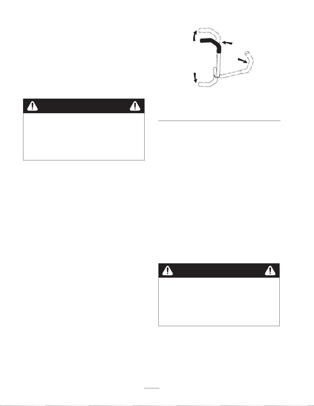
3
4
Figure 16
1. Motion control
lever—neutral lock
position
2
1
m–2715
2. Center unlock position
3. Forward
4. Backward
Driving Backward
1. Move the levers to the center, unlocked position.
2. To go backward, slowly pull the motion control levers
rearward (Fig. 16).
Driving Forward
1. Release the parking brake; refer to Releasing the
Parking Brake, page 17.
2. Move the levers to the center, unlocked position.
3. To go forward, slowly push the motion control levers
forward (Fig. 16).
Note: The engine will kill if the traction control levers are
moved with the parking brake engaged.
To go straight, apply equal pressure to both motion control
levers (Fig. 16).
To turn, release pressure on the motion control lever toward
the direction you want to turn (Fig. 16).
The farther you move the traction control levers in either
direction, the faster the machine will move in that direction.
To stop, pull the motion control levers to neutral.
To go straight, apply equal pressure to both motion control
levers (Fig. 16).
To turn, release pressure on the motion control lever toward
the direction you want to turn (Fig. 16).
To stop, push the motion control levers to neutral.
Stopping the Machine
To stop the machine, move the traction control levers to
neutral and separate to lock, disengage the power take off
(PTO), and turn the ignition key to Off to stop the engine.
Also set the parking brake when you leave the machine;
refer to Setting the Parking Brake, page 17. Remember to
remove the key from the ignition switch.
Caution
Children or bystanders may be injured if they
move or attempt to operate the tractor while it is
unattended.
Always remove the ignition and set the parking
brake when leaving the machine unattended, even
if just for a few minutes.
20
Page 21
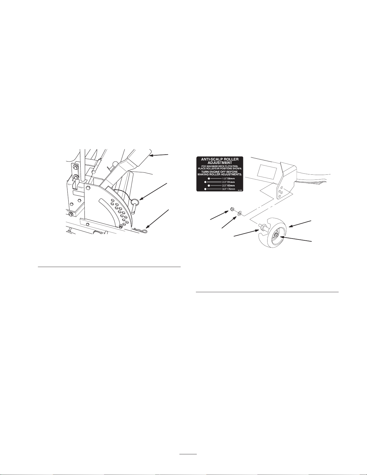
Adjusting the Height-of-Cut
The height-of-cut is adjusted from 1-1/2 to 4-1/2 inch (38
to 114 mm) in 1/4 inch (6 mm) increments by relocating the
clevis pin in different hole locations.
1. Raise the height-of-cut lever to the transport position
(also the 4-1/2 inch [114 mm] cutting height position)
(Fig. 17).
2. To adjust, remove the hairpin cotter and clevis pin from
the height-of-cut bracket (Fig. 17).
3. Select the hole in the height-of-cut bracket
corresponding to the height-of-cut desired, and insert
the clevis pin (Fig. 17).
4. Secure the clevis pin with the hairpin cotter (Fig. 17).
1
2
3
2. Stop the engine, remove the key, and wait for all
moving parts to stop before leaving the operating
position.
1. Disengage the power take off (PTO) and turn the
ignition key to Off. Move the control levers to the
neutral locked position and apply the parking brake.
Remove the key.
2. After adjusting the height-of-cut, remove the nut and
washer while holding the stud with a wrench (Fig. 18).
Note: Do not remove the wheel nut and washer (Fig. 18).
3. Select a hole so that the gage wheel is positioned to the
nearest corresponding height-of-cut desired (Fig. 18).
4. Reinstall the stud nut and washer (Fig. 18).
5. Repeat the adjustment on the other gage wheels.
m–4122
Figure 17
1. Height-of-cut lever
2. Clevis pin
3. Hairpin cotter
5. Lower the height-of-cut lever onto the clevis pin
(Fig. 17).
Adjusting the Anti-Scalp
Rollers
Whenever you change the height-of-cut it is recommended
to adjust the height of the anti-scalp rollers.
Adjusting the Outer Rollers
1. Disengage the PTO, move the motion control levers to
the neutral locked position and set the parking brake.
4
1
3
2
5
m–4167
Figure 18
1. Gage wheel
2. Stud
3. Washer
4. Nut
5. Wheel nut and washer.
Do not remove.
Adjusting the Center Rollers
1. Disengage the power take off (PTO) and turn the
ignition key to Off. Move the control levers to the
neutral locked position and apply the parking brake.
2. After adjusting the height-of-cut, remove the bolt and
nut (Fig. 19).
3. Select a hole so that the gage wheel is positioned to the
nearest corresponding height-of-cut desired (Fig. 19).
Note: Do not adjust the rollers to support the deck.
21
Page 22
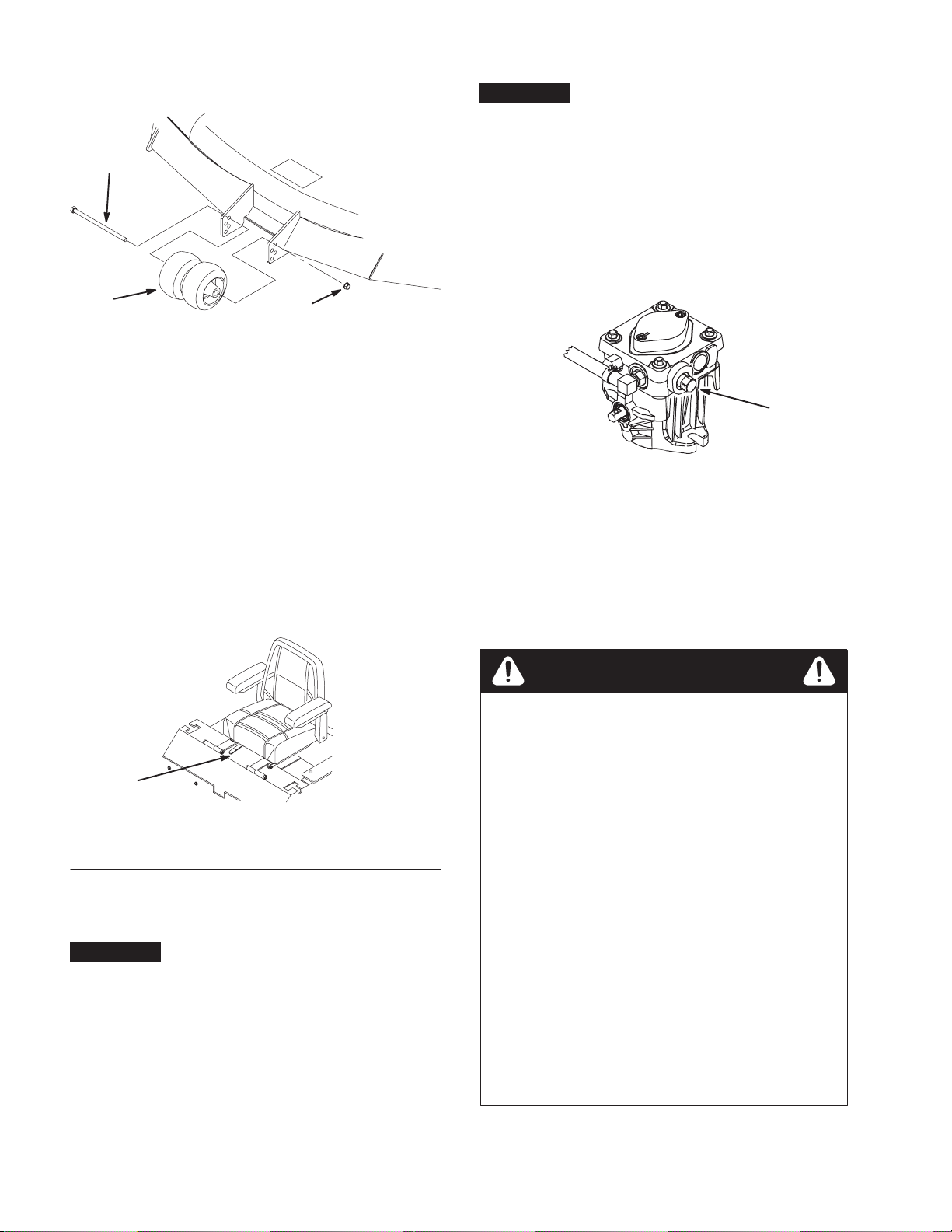
4. Reinstall the bolt, center rollers, and nut (Fig. 19).
Important Do not rotate the by–pass valves more than
1 turn. This prevents the valves from coming out of the
body and causing fluid to run out.
3
1
Figure 19
1. Center rollers and spacer
2. Nut
2
3. Bolt
m–4124
Positioning the Seat
The seat can move forward and backward. Position the seat
where you have the best control of the machine and are
most comfortable.
1. To adjust, move the lever sideways to unlock seat
(Fig. 20).
2. Slide the seat to the desired position and release the
lever to lock the seat in position.
Changing to Machine Operation
Turn the by-pass valves in to operate (Fig. 21).
Note: Do not over tighten the by–pass valves.
Note: The machine will not drive unless the by-pass valves
are turned in.
1
m–6279
Figure 21
1. By-pass valve
Operating with Side Discharge
The mower has a hinged grass deflector that disperses
clippings to the side and down toward the turf.
1
m–3655
Figure 20
1. Adjustment lever
Pushing the Machine by Hand
Important Always push the machine by hand. Never
tow the machine because hydraulic damage may occur.
To Push the Machine
1. Disengage the power take off (PTO) and turn the
ignition key to Off.
2. Rotate the by-pass valves counterclockwise 1 turn to
push. This allows hydraulic fluid to by-pass the pump
enabling the wheels to turn (Fig. 21).
Danger
Without the grass deflector, discharge cover, or
complete grass catcher assembly mounted in place,
you and others are exposed to blade contact and
thrown debris. Contact with rotating mower
blade(s) and thrown debris will cause injury or
death.
• Never remove the grass deflector from the
mower because the grass deflector routes
material down toward the turf. If the grass
deflector is ever damaged, replace it
immediately.
• Never put your hands or feet under the mower.
• Never try to clear discharge area or mower
blades unless you move the power take off
(PTO) to Off and rotate the ignition key to Off.
Also remove the key and pull the wire off the
spark plug(s).
• Make sure the grass deflector is in the down
position.
22
Page 23
Transporting the Machine
Use a heavy-duty trailer or truck to transport the machine.
Ensure that the trailer or truck has all necessary lighting
and marking as required by law. Please carefully read all
the safety instructions. Knowing this information could
help you, your family, pets, or bystanders avoid injury.
To transport the machine:
• Lock the brake and block the wheels.
• Securely fasten the machine to the trailer or truck with
straps, chains, cable, or ropes.
• Secure a trailer to the towing vehicle with safety chains.
Warning
Driving on street or roadway without turn signals,
lights, reflective markings, or a slow moving
vehicle emblem is dangerous and can lead to
accidents causing personal injury.
Do not drive machine on a public street or
roadway.
Warning
Loading a unit onto a trailer or truck increases the
possibility of backward tip–over and could cause
serious injury or death.
• Use extreme caution when operating a unit on a
ramp.
• Use only a single, full width ramp; DO NOT use
individual ramps for each side of the unit.
• If individual ramps must be used, use enough
ramps to create an unbroken ramp surface
wider than the unit.
• Do not exceed a 15 degree angle between ramp
and ground or between ramp and trailer or
truck.
• Avoid sudden acceleration while driving unit up
a ramp to avoid tipping backward.
• Avoid sudden deceleration while backing unit
down a ramp to avoid tipping backward.
1
4
Loading Machines
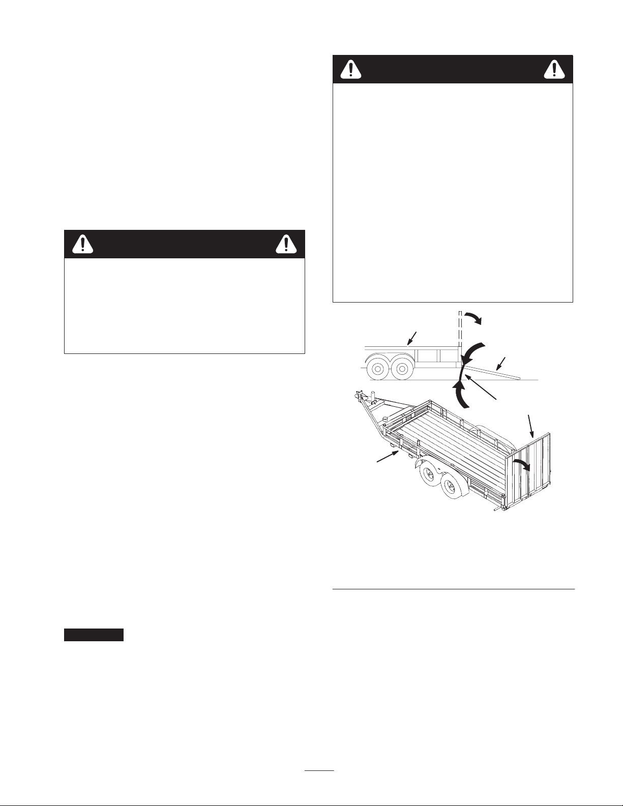
Use extreme caution when loading units on trailers or
trucks. One full width ramp that is wide enough to extend
beyond the rear tires is recommended instead of individual
ramps for each side of the unit (Fig. 22). The lower rear
section of the tractor frame extends back between the rear
wheels and serves as a stop for tipping backward. Having a
full width ramp provides a surface for the frame members
to contact if the unit starts to tip backward. If it is not
possible to use one full width ramp, use enough individual
ramps to simulate a full width continuous ramp.
The ramp should be long enough so that the angles do not
exceed 15 degrees (Fig. 22). A steeper angle may cause
mower deck components to get caught as the unit moves
from ramp to trailer or truck. Steeper angles may also cause
the unit to tip backward. If loading on or near a slope,
position the trailer or truck so it is on the down side of the
slope and the ramp extends up the slope. This will
minimize the ramp angle. The trailer or truck should be as
level as possible.
Important Do Not attempt to turn the unit while on the
ramp; you may lose control and drive off the side.
Avoid sudden acceleration when driving up a ramp and
sudden deceleration when backing down a ramp. Both
maneuvers can cause the unit to tip backward.
1
m–6841
1. Trailer
2. Full width ramp
3. Not greater than
15 degrees
Figure 22
4. Full width ramp—side
view
2
3
23
Page 24

Tips for Mowing Grass
Fast Throttle Setting
For best mowing and maximum air circulation, operate the
engine at fast. Air is required to thoroughly cut grass
clippings, so do not set the height-of-cut so low as to totally
surround the mower by uncut grass. Always try to have one
side of the mower free from uncut grass, which allows air
to be drawn into the mower.
Cutting a Lawn for the First Time
Cut grass slightly longer than normal to ensure that the
cutting height of the mower does not scalp any uneven
ground. However, the cutting height used in the past is
generally the best one to use. When cutting grass longer
than 6 inches (15 cm) tall, you may want to cut the lawn
twice to ensure an acceptable quality of cut.
Cut 1/3 of the Grass Blade
It is best to cut only about 1/3 of the grass blade. Cutting
more than that is not recommended unless grass is sparse,
or it is late fall when grass grows more slowly.
Mowing Direction
Alternate mowing direction to keep the grass standing
straight. This also helps disperse clippings which enhances
decomposition and fertilization.
Long Grass
If the grass is ever allowed to grow slightly longer than
normal, or if it contains a high degree of moisture, raise the
cutting height higher than usual and cut the grass at this
setting. Then cut the grass again using the lower, normal
setting.
When Stopping
If the machine’s forward motion must be stopped while
mowing, a clump of grass clippings may drop onto your
lawn. To avoid this, move onto a previously cut area with
the blades engaged.
Keep the Underside of the Mower Clean
Clean clippings and dirt from the underside of the mower
after each use. If grass and dirt build up inside the mower,
cutting quality will eventually become unsatisfactory.
Blade Maintenance
Maintain a sharp blade throughout the cutting season
because a sharp blade cuts cleanly without tearing or
shredding the grass blades. Tearing and shredding turns
grass brown at the edges, which slows growth and increases
the chance of disease. Check the cutter blades daily for
sharpness, and for any wear or damage. File down any
nicks and sharpen the blades as necessary. If a blade is
damaged or worn, replace it immediately with a genuine
Toro replacement blade.
Mow at Correct Intervals
Normally, mow every four days. But remember, grass
grows at different rates at different times. So to maintain
the same cutting height, which is a good practice, mow
more often in early spring. As the grass growth rate slows
in mid summer, mow less frequently. If you cannot mow
for an extended period, first mow at a high cutting height;
then mow again two days later at a lower height setting.
Cutting Speed
To improve cut quality, use a slower ground speed.
Avoid Cutting Too Low
If the cutting width of the mower is wider than the mower
you previously used, raise the cutting height to ensure that
uneven turf is not cut too short.
24
Page 25

Maintenance
Note: Determine the left and right sides of the machine from the normal operating position.
Recommended Maintenance Schedule
Maintenance Service
Interval
Maintenance Procedure
• Check hydraulic fluid level
After First 5 Hours
• Change engine oil
• Change hydraulic filter
• Check engine oil level
Each Use
• Check safety system
• Clean engine air intake
• Clean mower housing
Every 5 Hours
• Check cutting blades
• Grease blade spindle bearings
• Check hydraulic fluid level
• Grease mower support and push arms
• Grease brake lever
Every 25 Hours
• Oil linkage bushings
• Service foam air cleaner
• Check battery electrolyte
• Check tire pressure
• Grease both idler pulley pivots
Every 40 Hours • Grease front tires
1
1
1
Every 50 Hours • Check belts for wear/cracks
• Change engine oil
Every 100 Hours
• Service paper air cleaner
• Check spark plug(s)
• Check hydraulic lines
• Change hydraulic filter
• Change oil filter
Every 200 Hours
• Replace paper air cleaner
• Replace fuel filter
• Grease brake lever pivot
Every 300 Hours • Clean cooling system
Every 500 Hours or at
Storage
• Adjust and grease caster pivot
• Adjust wheel hub slotted nut
• Perform all maintenance procedures listed above before storage
Before Storage
• Drain gasoline
• Charge battery, disconnect cables
• Paint chipped surfaces
1
More often in dusty, dirty conditions
1
1
1
1
1
25
Page 26
Important Refer to your engine operator’s manual for additional maintenance procedures.
Caution
If you leave the key in the ignition switch, someone could accidently start the engine and
seriously injure you or other bystanders.
Remove the key from the ignition and disconnect the wire from the spark plug(s) before you do
any maintenance. Set the wire aside so that it does not accidentally contact the spark plug.
Servicing the Cutting Blades
Maintain sharp blades throughout the cutting season
because sharp blades cut cleanly without tearing or
shredding the grass blades. Tearing and shredding turns
grass brown at the edges, which slows growth and increases
the chance of disease.
Check the cutter blades daily for sharpness, and for any
wear or damage. File down any nicks and sharpen the
blades as necessary. If a blade is damaged or worn, replace
it immediately with a genuine Toro replacement blade. For
convenient sharpening and replacement, you may want to
keep extra blades on hand.
Danger
A worn or damaged blade can break, and a piece
of the blade could be thrown into the operator’s or
bystander’s area, resulting in serious personal
injury or death.
• Inspect the blade periodically for wear or
damage.
• Replace a worn or damaged blade.
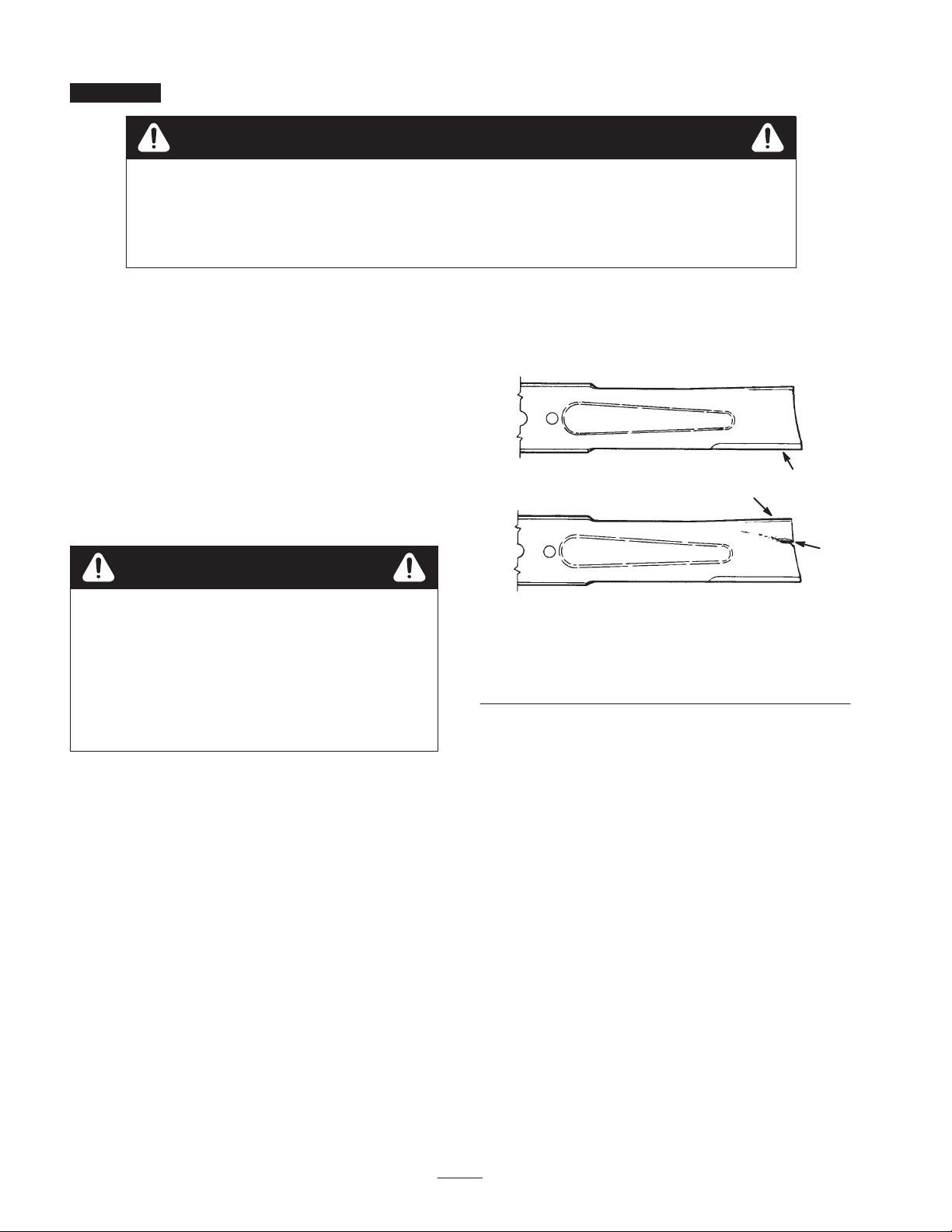
2. Inspect the blades, especially the curved area (Fig. 23).
If you notice any damage, wear, or a slot forming in this
area (item 3 in Fig. 23), immediately install a new
blade.
1
3
m–151
1. Cutting edge
2. Curved area
2
Figure 23
3. Wear/slot forming
Checking for Bent Blades
Before Inspecting or Servicing the Blades
Park the machine on a level surface, disengage the blade
control (PTO) and set the parking brake. Turn the ignition
key to Off. Remove the key and disconnect the spark plug
wire(s) from the spark plug(s).
Inspecting the Blades
1. Inspect the cutting edges (Fig. 23). If the edges are not
sharp or have nicks, remove and sharpen the blades;
refer to Sharpening the Blades, page 27.
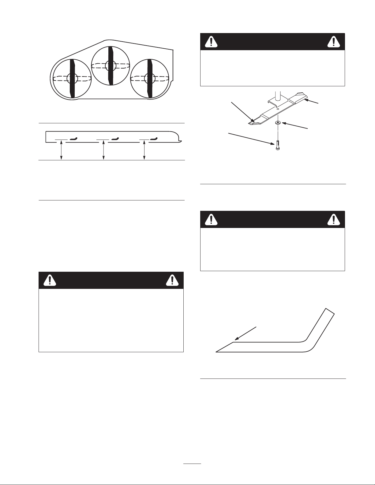
1. Rotate the blades until the ends face forward and
backward (Fig. 24). Measure from a level surface to the
cutting edge of the blades (Fig. 25). Note this
dimension.
26
Page 27
Front
Warning
Contact with sharp blade can cause serious injury.
Wear gloves or wrap sharp edges of the blade with
a rag.
m–1078
Figure 24
MEASURE FROM
CUTTING EDGE TO A
LEVEL SURFACE
m–2539
Figure 25
2. Rotate the opposite ends of the blades forward.
3. Measure from a level surface to the cutting edge of the
blades at the same position as in step 1 above. The
difference between the dimensions obtained in steps 1
and 3 must not exceed 1/8 inch (3 mm). If this
dimension exceeds 1/8 inch (3 mm), the blade is bent
and must be replaced; refer to Removing the Blades and
Installing the Blades, page 28.
1
4
3
Figure 26
1. Sail area of blade
2. Blade
3. Spring disk
4. Blade bolt
Sharpening the Blades
Warning
When sharpening blade, pieces of blade could be
thrown and cause serious injury.
Wear proper eye protection when sharpening
blade.
2
m–4318
Warning
A blade that is bent or damaged could break apart
and could seriously injure or kill you or
bystanders.
• Always replace bent or damaged blade with a
new blade.
• Never file or create sharp notches in the edges
or surfaces of blade.
Removing the Blades
The blades must be replaced if a solid object is hit, if the
blade is out of balance, or is bent. To ensure optimum
performance and continued safety conformance of the
machine, use genuine Toro replacement blades.
Replacement blades made by other manufacturers may
result in non-conformance with safety standards.
Hold the blade end using a rag or thickly-padded glove.
Remove the blade bolt, spring disk, and blade from the
spindle shaft (Fig. 26).
1. Use a file to sharpen the cutting edge at both ends of the
blade (Fig. 27). Maintain the original angle. The blade
retains its balance if the same amount of material is
removed from both cutting edges.
1
m–1854
Figure 27
1. Sharpen at original angle
2. Check the balance of the blade by putting it on a blade
balancer (Fig. 28). If the blade stays in a horizontal
position, the blade is balanced and can be used. If the
blade is not balanced, file some metal off of the end of
the sail area only (Fig. 26). Repeat this procedure until
the blade is balanced.
27
Page 28
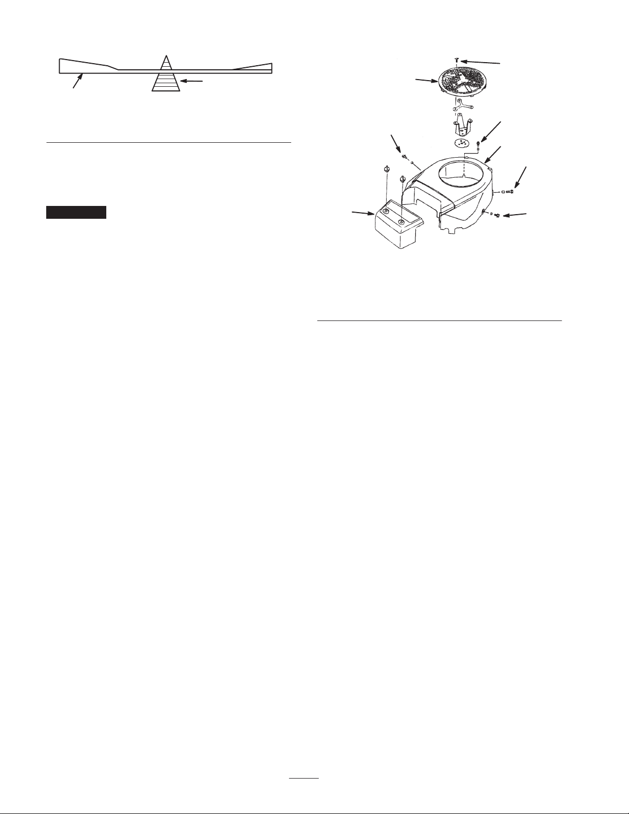
2
1
Figure 28
1. Blade 2. Balancer
Installing the Blades
1. Install the blade onto the spindle shaft (Fig. 26).
4
1
m–1855
5
5
2
6
Important The curved part of the blade must be
pointing upward toward the inside of the mower to ensure
proper cutting.
2. Install the flat washer, lock washer, and blade bolt
(Fig. 26). Torque the blade bolt to 85–110 ft-lb
(115–150 N⋅m).
Cleaning the Cooling System
Clean the air intake screen from grass and debris before
each use.
Clean the cooling fins and engine shrouds every 300 hours
or yearly, which ever comes first.
1. Disengage the PTO, move the motion control levers to
the neutral locked position and set the parking brake.
2. Stop the engine, remove the key, and wait for all
moving parts to stop before leaving the operating
position.
3. Remove the air intake screen, air cleaner cover, fan
housing, and bolts (Fig. 29).
4. Clean debris and grass from the engine shrouds and
cooling fins.
5. Reinstall the air intake screen, air cleaner cover, fan
housing, and bolts (Fig. 29). Torque the bolts to 4.3 ft-lb
(5.8 N⋅m).
3
5
m–4369
Figure 29
1. Air intake screen
2. Fan housing
3. Air cleaner cover
4. M6 x 10mm bolt
5. M6 x 12mm bolt
6. M6 x 20mm bolt
Servicing the Air Cleaner
Primary Filter: Check and/or replace after every
200 operating hours or more often in dusty conditions.
Safety Filter: Replace after every 600 operating hours.
Note: Check the filters more frequently if operating
conditions are extremely dusty or sandy.
Removing the Filters
1. Disengage the PTO, move the motion control levers to
the neutral locked position and set the parking brake.
2. Stop the engine, remove the key, and wait for all
moving parts to stop before leaving the operating
position.
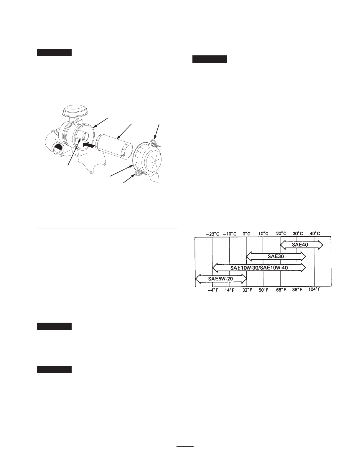
3. Release the latches on the air cleaner and pull the air
cleaner cover off of the air cleaner body (Fig. 30).
4. Clean the inside of the air cleaner cover with
compressed air.
5. Gently slide the primary filter out of the air cleaner
body (Fig. 30). Avoid knocking the filter into the side of
the body.
28
Page 29
6. Remove the safety filter only if you intend to replace
it.
Important Never attempt to clean the safety filter. If
the safety filter is dirty, then the primary filter is damaged
and you should replace both filters.
3. Carefully slide the primary filter over the safety filter
(Fig. 30). Ensure that it is fully seated by pushing on the
outer rim of the filter while installing it.
Important Do not press on the soft inside area of the
filter.
7. Inspect the primary filter for damage by looking into
the filter while shining a bright light on the outside of
the filter. Holes in the filter will appear as bright spots.
If the filter is damaged discard it.
3
4
1
5
2
1
m–4815
Figure 30
1. Latches
2. Air cleaner cover
3. Air filter body
4. Primary filter
5. Safety filter
Servicing the Primary Filter
4. Install the air cleaner cover with the side indicated as
UP facing up and secure the latches (Fig. 30).
Servicing the Engine Oil
Change the oil:
• After the first 8 operating hours.
• After every 100 operating hours.
Note: Change the oil more frequently when operating
conditions are extremely dusty or sandy.
Oil Type: Detergent oil (API service SG or SH)
Crankcase Capacity:
• 51 oz. (1.5 l) (When the oil filter is not removed)
• 57 oz. (1.7 l) (When the oil filter is removed)
Viscosity: See the table below.
USE THESE SAE VISCOSITY OILS
Check and/or replace it after 200 operating hours.
If the primary filter is dirty, bent, or damaged then replace
the filter.
Do not clean the primary filter.
Servicing the Safety Filter
Replace it after 600 operating hours.
Important Never attempt to clean the safety filter. If
the safety filter is dirty, then the primary filter is damaged
and you should replace both filters.
Installing the Filters
Important To prevent engine damage, always operate
the engine with both air filters and cover installed.
1. If installing new filters, check each filter for shipping
damage. Do not use a damaged filter.
2. If the safety filter is being replaced, carefully slide it
into the filter body (Fig. 30).
m–4292
Checking the Oil Level
Check the engine oil level daily.
1. Park the machine on a level surface.
2. Disengage the PTO, move the motion control levers to
the neutral locked position and set the parking brake.
3. Stop the engine, remove the key, and wait for all
moving parts to stop before leaving the operating
position.
4. Clean around the oil dipstick (Fig. 31) so that dirt
cannot fall into the filler hole and damage the engine.
5. Unscrew the oil dipstick and wipe the end clean
(Fig. 31).
29
Page 30
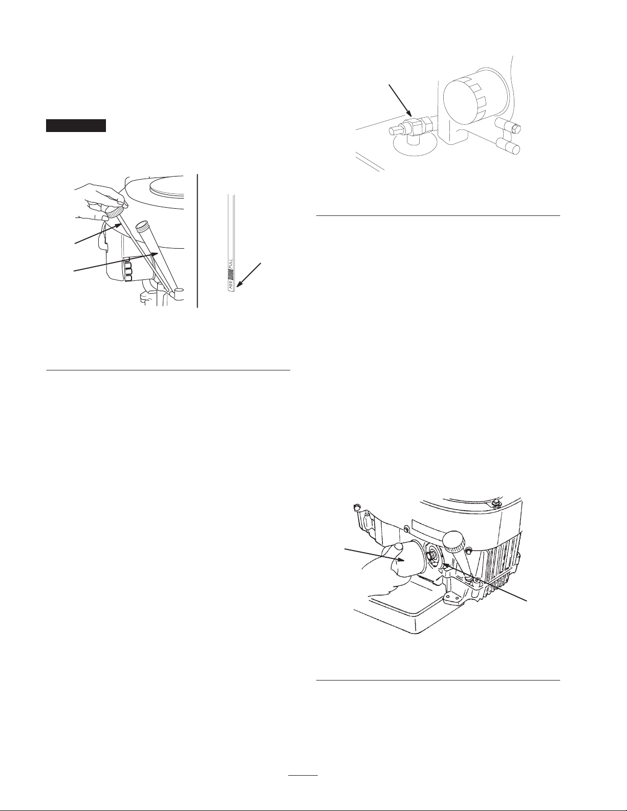
6. Slide the oil dipstick fully into the filler tube. Do not
thread it onto the tube (Fig. 31). Pull the dipstick out
and look at the end. If the oil level is low, slowly pour
only enough oil into the filler tube to raise the level to
the full mark.
Important Do not overfill the crankcase with oil
because the engine may be damaged. Do not run engine
with oil below the low mark because the engine may be
damaged.
1
3
2
1
m–5625
Figure 32
1. Oil drain valve
6. Slowly pour approximately 80% of the specified oil into
the filler cap (Fig. 31). Refer to Servicing the Engine
Oil, page 29.
7. Check the oil level; refer to Checking the Oil Level,
page 29.
m–4368
Figure 31
1. Oil dipstick
2. Filler tube
3. Dipstick end
Changing the Oil
1. Start the engine and let it run for five minutes. This
warms the oil so that it drains better.
2. Park the machine so that the drain side is slightly lower
than the opposite side to ensure that the oil drains
completely. Disengage the power take off (PTO), set the
parking brake, stop the engine, and remove the key.
3. Place a pan below the oil drain. Use either a flat screw
driver, 3/8 inch wrench, or 10 mm wrench to open the
valve (Fig. 32).
4. Rotate the valve end clockwise to close the valve.
Rotate the valve end counterclockwise to open the valve
(Fig. 32).
5. When the oil has drained completely, close the drain
valve (Fig. 32).
Note: Dispose of the used oil at a certified recycling center.
8. Slowly add additional oil to bring it to the full mark.
Changing the Oil Filter
Replace the oil filter every 200 hours or every other oil
change.
Note: Change the oil filter more frequently when operating
conditions are extremely dusty or sandy.
1. Drain the oil from the engine; refer to Changing the Oil,
page 30.
2. Remove the old filter (Fig. 33).
3. Apply a thin coat of new oil to the rubber gasket on the
replacement filter (Fig. 33).
1
2
m–4288
Figure 33
1. Oil filter 2. Adapter
4. Install the replacement oil filter to the adapter. Turn the
oil filter clockwise until the rubber gasket contacts the
filter adapter; then tighten the filter an additional
3/4 turn (Fig. 33).
30
Page 31
5. Fill the crankcase with the proper type of new oil; refer
to Servicing the Engine Oil, page 29.
Important Always replace the spark plug(s) when it
has a black coating, worn electrodes, an oily film, or
cracks.
Servicing the Spark Plug
Check the spark plug(s) after every 100 operating hours.
Make sure that the air gap between the center and side
electrodes is correct before installing the spark plug. Use a
spark plug wrench for removing and installing the spark
plug(s) and a gapping tool/feeler gauge to check and adjust
the air gap. Install a new spark plug(s) if necessary.
Type: NGK BPR5ES (or equivalent)
Air Gap: 0.030 inch (0.76 mm)
Removing the Spark Plug(s)
1. Disengage the PTO, move the motion control levers to
the neutral locked position and set the parking brake.
2. Stop the engine, remove the key, and wait for all
moving parts to stop before leaving the operating
position.
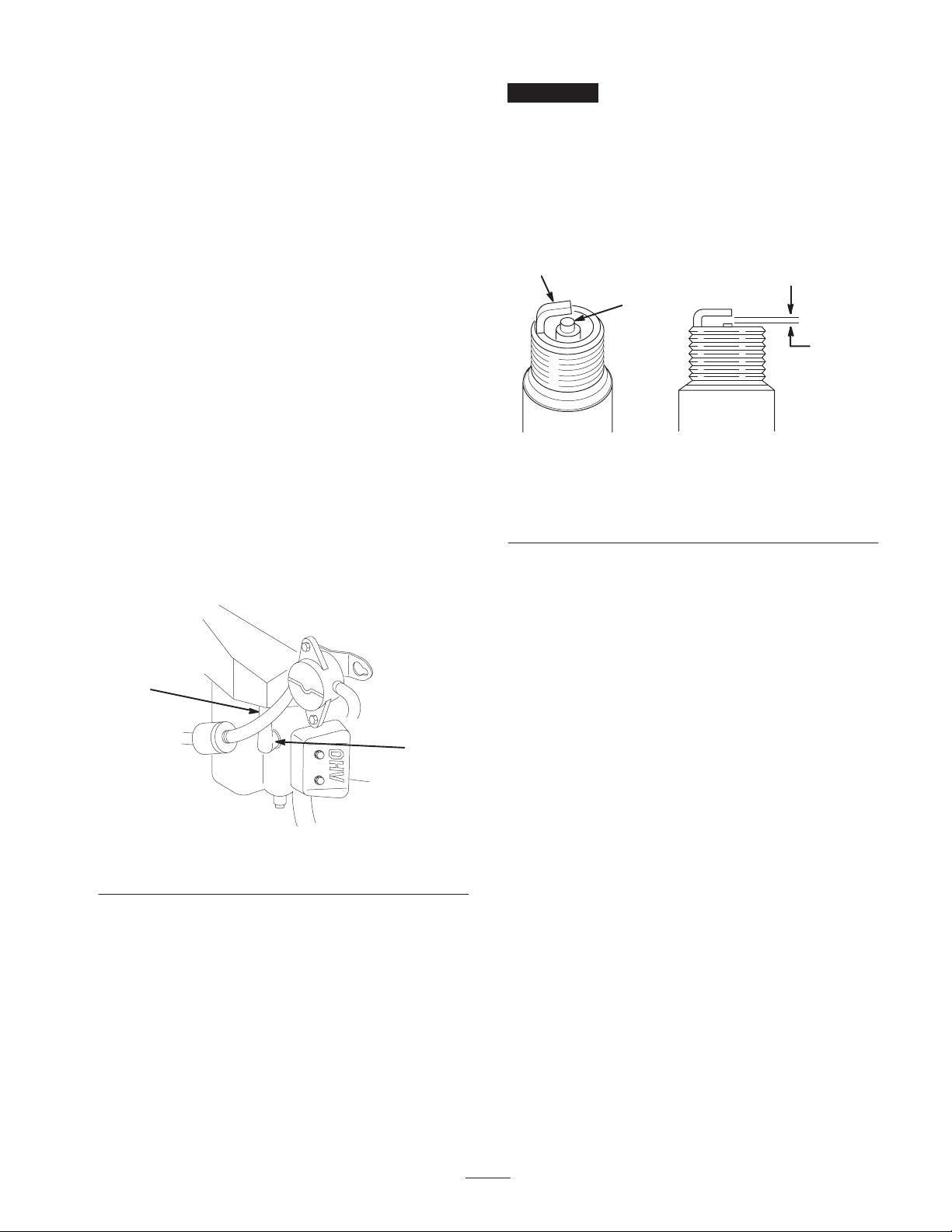
3. Pull the wire(s) off of the spark plug(s) (Fig. 34). Clean
around the spark plug(s) to prevent dirt from falling into
the engine and potentially causing damage.
4. Remove the spark plug(s).
2. Clean the electrode by scraping or with a wire brush to
remove carbon deposits and wetness.
3. Check the gap between the center and side electrodes
(Fig. 35). Bend the side electrode (Fig. 35) if the gap is
not correct.
2
3
1
0.030 inch
(0.76 mm)
m–3215
Figure 35
1. Center electrode insulator
2. Side electrode
3. Air gap (not to scale)
Installing the Spark Plug(s)
1
2
m–4294
Figure 34
1. Spark plug wire installed 2. Spark plug
Checking the Spark Plug
Clean or replace the spark plug and set the gap every
100 hours.
1. Look at the center of the spark plug(s) (Fig. 35). If you
see light brown or gray on the insulator, the engine is
operating properly. A black coating on the insulator
usually means the air cleaner is dirty.
1. Install the spark plug(s). Make sure that the air gap is
set correctly.
2. Tighten the spark plug(s) to 16 ft-lb (22 N⋅m).
3. Push the wire(s) onto the spark plug(s) (Fig. 34).
Replacing the Fuel Filter
Replace the fuel filter after every 200 operating hours or
yearly, whichever occurs first.
Never install a dirty filter if it is removed from the fuel line.
1. Disengage the PTO, move the motion control levers to
the neutral locked position and set the parking brake.
2. Stop the engine, remove the key, and wait for all
moving parts to stop before leaving the operating
position.
3. Allow the machine to cool down.
4. Stop the engine, remove the key, and wait for all
moving parts to stop before leaving the operating
position.
5. Close the fuel shut-off valve on the console.
6. Squeeze the ends of the hose clamps together and slide
them away from the filter (Fig. 36).
7. Remove the filter from the fuel lines.
31
Page 32
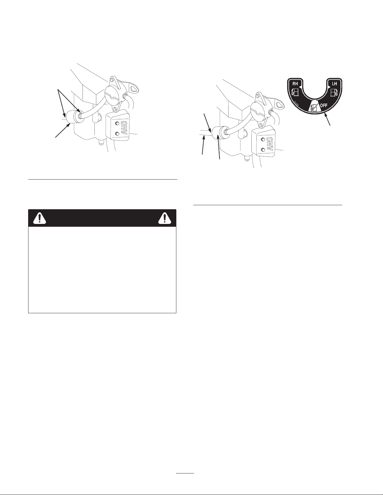
8. Install a new filter and move the hose clamps close to
the filter (Fig. 37).
Note: Now is the best time to install a new fuel filter
because the fuel tank is empty.
9. Open the fuel shut-off valve on the console.
2
1
M–4294
Figure 36
1. Filter 2. Hose clamp
Draining the Fuel Tank
Danger
In certain conditions, gasoline is extremely
flammable and highly explosive. A fire or
explosion from gasoline can burn you and others
and can damage property.
• Drain gasoline from the fuel tank when the
engine is cold. Do this outdoors in an open area.
Wipe up any gasoline that spills.
• Never smoke when draining gasoline, and stay
away from an open flame or where a spark may
ignite the gasoline fumes.
1. Park the machine on a level surface to ensure that the
fuel tanks drain completely. Then disengage the power
take off (PTO), set the parking brake, stop the engine,
and remove the key.
2. Close the fuel shut-off valve (Fig. 37).
3. Loosen the hose clamp at the fuel filter and slide it up
the fuel line away from the fuel filter (Fig. 37).
4. Pull the fuel line off of the fuel filter (Fig. 37).
6. Install the fuel line onto the fuel filter. Slide the hose
clamp close to the fuel filter to secure the fuel line
(Fig. 37).
3
1
4
1. Fuel shut-off valve
2. Fuel filter
2
Figure 37
3. Hose clamp
4. Fuel line
M–4294
Greasing and Lubrication
Lubricate the machine when shown on the Check Service
Reference Aid decal (Fig. 38). Grease more frequently
when operating conditions are extremely dusty or sandy.
Grease with No. 2 general purpose lithium base or
molybdenum base grease.
How to Grease
1. Disengage the PTO, move the motion control levers to
the neutral locked position and set the parking brake.
2. Stop the engine, remove the key, and wait for all
moving parts to stop before leaving the operating
position.
3. Clean the grease fittings with a rag. Make sure to scrape
any paint off of the front of the fitting(s).
4. Connect a grease gun to the fitting. Pump grease into
the fittings until grease begins to ooze out of the
bearings.
5. Open the fuel shut-off valve for the left and right tanks.
Allow gasoline to drain into a gas can or drain pan
(Fig. 37).
5. Wipe up any excess grease.
32
Page 33
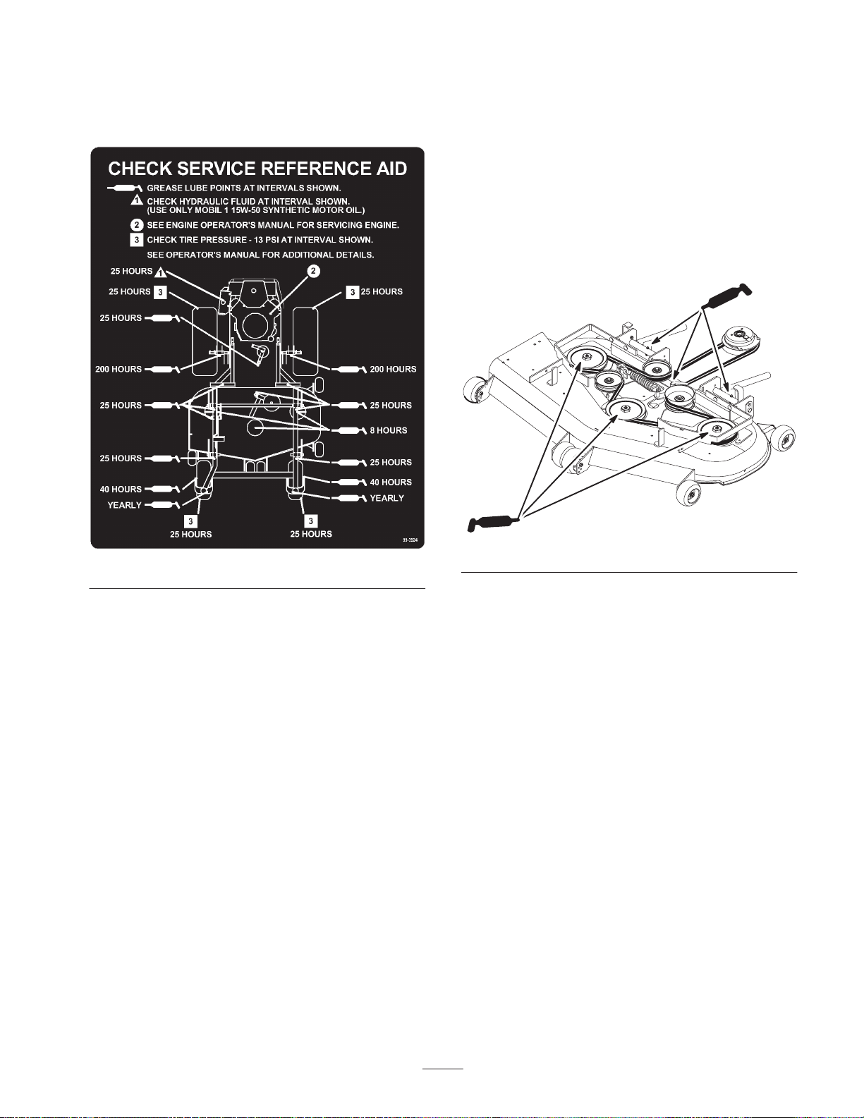
Where to Add Grease
Lubricate the grease fittings as shown on the Check
Service Reference Aid decal (Fig. 38).
1. Disengage the PTO, move the motion control levers to
the neutral locked position and set the parking brake.
2. Stop the engine, remove the key, and wait for all
moving parts to stop before leaving the operating
position.
3. Grease the fittings on the three spindle bearings
(Fig. 39).
4. Grease the idler pulley pivot (Fig. 39).
5. Grease the fittings on the push arms (Fig. 39).
Figure 38
Greasing the Front Caster Pivots
Lubricate the front caster pivots once a year.
1. Remove the dust cap and adjust the caster pivots. Keep
dust cap off until greasing is done. Refer to Adjusting
the Caster Pivot Bearing, page 38.
2. Remove the hex plug. Thread a grease zerk into hole.
3. Pump grease into zerk until it oozes out around top
bearing.
4. Remove grease zerk in hole. Reinstall hex plug and cap.
Greasing the Bearings
The cutting unit must be lubricated regularly; refer to the
Recommended Maintenance Schedule, page 25. Grease
with No. 2 general purpose lithium base or molybdenum
base grease.
M–4159
Figure 39
Where to Add Light Oil or Spray
Lubrication
Lubricate the machine in the following areas with spray
type lubricant or light oil. Lubricate every 160 hours.
• Seat switch actuator
• Brake handle pivot
• Brake rod bushings
• Motion control bronze bushings
Checking the Tire Pressure
Maintain the air pressure in the front and rear tires as
specified. Uneven tire pressure can cause uneven cut.
Check the pressure at the valve stem after every
33
Page 34
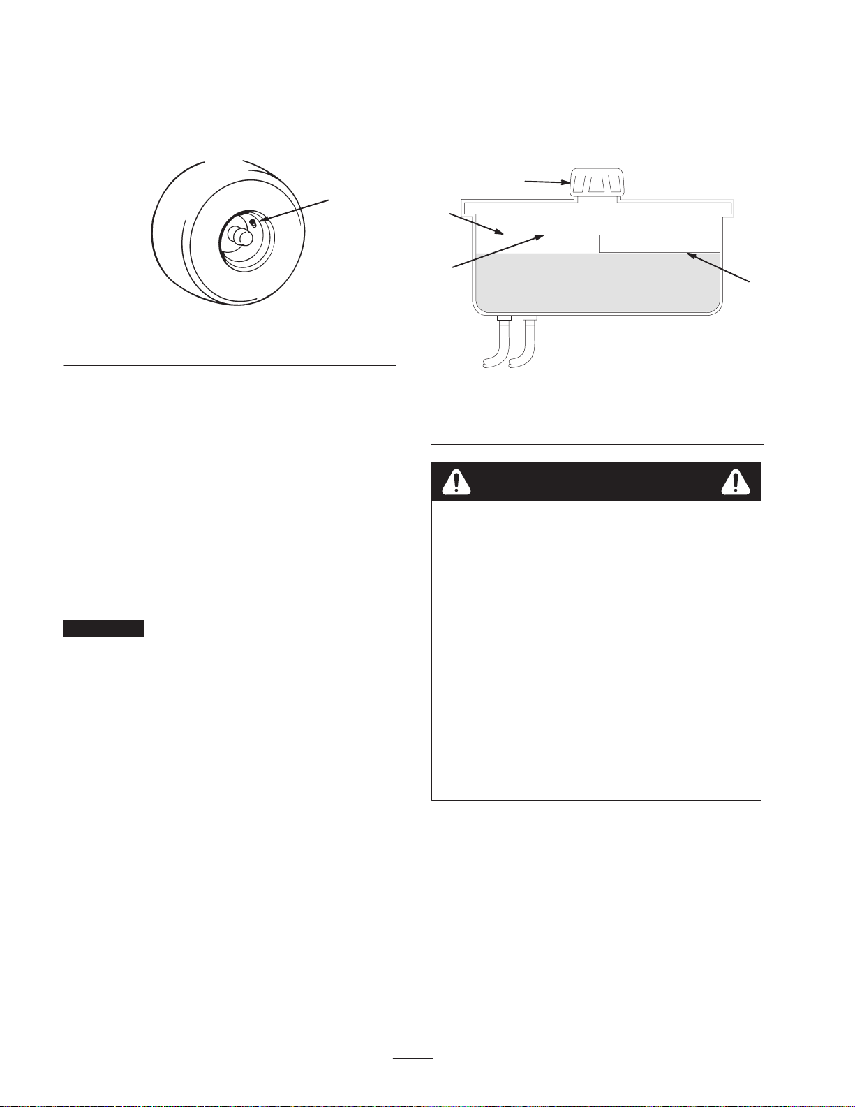
50 operating hours or monthly, whichever occurs first
(Fig. 40). Check the tires when they are cold to get the most
accurate pressure reading.
Pressure: 13 psi (90 kPa) drive wheels and caster wheels
1
7. If required, add fluid to the hydraulic tank.
Note: The fluid level should be to the top of the hot level
of the baffle, when the fluid is hot (Fig. 41).
8. Install cap on filler neck.
1
2
m–1872
Figure 40
1. Valve stem
Servicing the Hydraulic System
Checking the Hydraulic Fluid
Check the hydraulic fluid level:
• Before the engine is first started.
• After the first 8 operating hours.
• After every 25 operating hours.
Fluid Type: Mobil 1 15W-50 synthetic motor oil or
equivalent synthetic oil.
Important Use oil specified or equivalent. Other fluids
could cause system damage.
Hydraulic System Oil Capacity: 67 oz. (2.0 l)
Note: There are two ways of checking the hydraulic oil.
One is when the oil is warm and one is when the oil is cold.
The baffle inside the tank has two levels depending if the
oil is warm or cold.
1. Position machine on a level surface and set the parking
brake.
4
Figure 41
1. Cap
2. Baffle
3. Cold fluid level—full
4. Hot fluid level—full
Warning
Hydraulic fluid escaping under pressure can
penetrate skin and cause injury.
• If hydraulic fluid is injected into the skin it must
be surgically removed within a few hours by a
doctor familiar with this type of injury.
Gangrene may result if this is not done.
• Keep body and hands away from pin hole leaks
or nozzles that eject high pressure hydraulic
fluid.
• Use cardboard or paper to find hydraulic leaks.
• Safely relieve all pressure in the hydraulic
system before performing any work on the
hydraulic system.
• Make sure all hydraulic fluid hoses and lines are
in good condition and all hydraulic connections
and fittings are tight before applying pressure to
hydraulic system.
3
m–5615
2. Clean area around filler neck of hydraulic tank
(Fig. 41).
3. Remove the cap from the filler neck. Look inside to
check if there is fluid in the reservoir (Fig. 41).
4. If there is no fluid, add fluid to the reservoir until it
reaches the cold level of the baffle.
5. Run the machine at low idle for 15 minutes to allow any
air to purge out of the system and warm the fluid. Refer
to Starting and Stopping the Engine on page 18.
6. Recheck the fluid level while the fluid is warm. The
fluid should be between cold and hot.
34
Page 35
Replacing the Hydraulic Filter
Change the hydraulic filter:
• After the first 8 operating hours.
• After every 200 operating hours.
Use summer filter above 32°F (0°C)
Use winter filter below 32°F (0°C)
1. Disengage the PTO, move the motion control levers to
the neutral locked position and set the parking brake.
2. Stop the engine, remove the key, and wait for all
moving parts to stop before leaving the operating
position.
Important Do not substitute automotive oil filter or
severe hydraulic system damage may result.
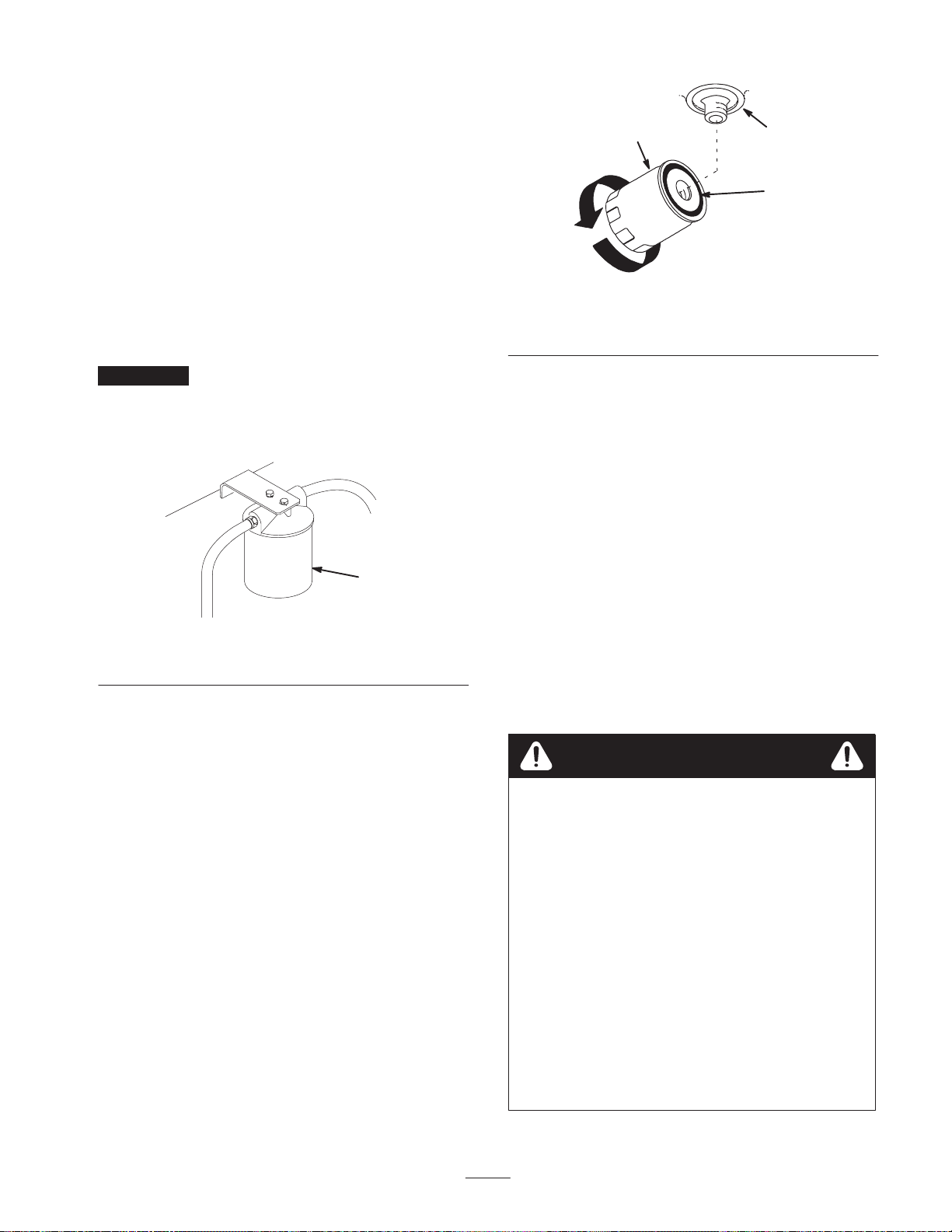
3. Place drain pan under filter, remove the old filter and
wipe the filter adapter gasket surface clean (Fig. 42).
1
M–4763
Figure 42
1. Hydraulic filter
1
3
2
m–1256
Figure 43
1. Hydraulic filter
2. Gasket
3. Adapter
Bleeding the Hydraulic System
The traction system is self bleeding, however, it may be
necessary to bleed the system if fluid is changed or after
work is performed on the system.
1. Raise rear of the machine so wheels are off the ground
and support with jack stands.
2. Start the engine and run at low idle speed. Engage the
lever and traction on one side and spin the wheel by
hand.
3. When the wheel begins to spin on its own, keep it
engaged until wheel drives smoothly. (minimum
2 minutes)
4. Check hydraulic fluid level and add as required to
maintain proper level.
4. Apply a thin coat hydro fluid to the rubber gasket on the
replacement filter (Fig. 43).
5. Install the replacement hydraulic filter onto the filter
adapter. Do not tighten.
6. Fill the hydraulic tank with hydraulic fluid until the
fluid overflows the filter and then turn the oil filter
clockwise until the rubber gasket contacts the filter
adapter, then tighten the filter an additional 1/2 turn
(Fig. 43).
7. Clean up any spilled fluid.
8. Add fluid to the cold level of the baffle in the hydraulic
tank.
9. Start the engine and let it run for about two minutes to
purge air from the system. Stop the engine and check
for leaks. If one or both wheels will not drive, refer
Bleeding Hydraulic System, page 35.
10.Recheck the fluid level while the fluid is warm. The
fluid should be between cold and hot.
11. If required, add fluid to the hydraulic tank. Do not
overfill.
5. Repeat this procedure on the opposite wheel.
Warning
Hydraulic fluid escaping under pressure can
penetrate skin and cause injury.
• If hydraulic fluid is injected into the skin it must
be surgically removed within a few hours by a
doctor familiar with this type of injury.
Gangrene may result if this is not done.
• Keep body and hands away from pin hole leaks
or nozzles that eject high pressure hydraulic
fluid.
• Use cardboard or paper to find hydraulic leaks.
• Safely relieve all pressure in the hydraulic
system before performing any work on the
hydraulic system.
• Make sure all hydraulic fluid hoses and lines are
in good condition and all hydraulic connections
and fittings are tight before applying pressure to
hydraulic system.
35
Page 36
Checking the Hydraulic Lines
After every 100 operating hours, check hydraulic lines and
hoses for leaks, loose fittings, kinked lines, loose mounting
supports, wear, weather and chemical deterioration. Make
necessary repairs before operating.
Note: Keep areas around hydraulic system clean from grass
and debris build up.
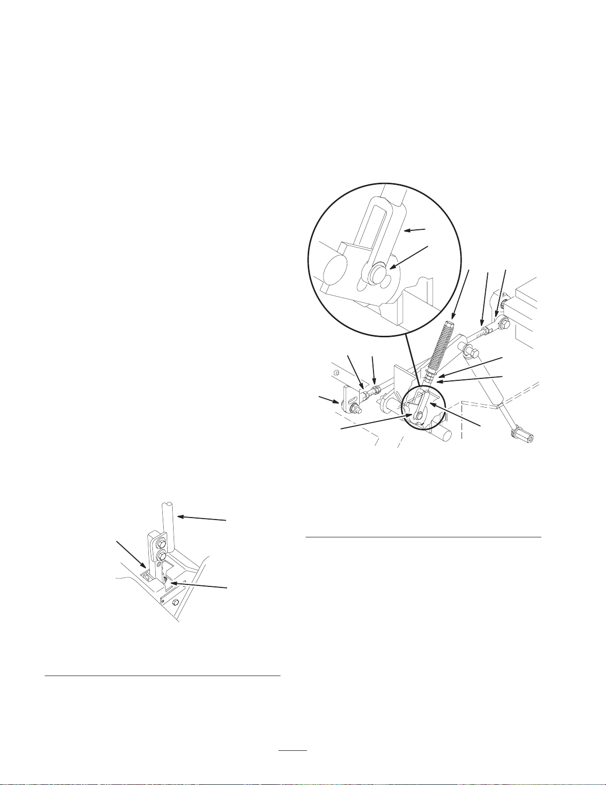
9. Apply slight rearward pressure on the motion control
lever, turn the head of the adjustment bolt in the
appropriate direction until the control lever is centered
in neutral lock position (Fig. 44).
Note: Keeping rearward pressure on the lever will keep the
pin at the end of the slot and allow the adjustment bolt to
move the lever to the appropriate position.
10.Tighten the nut and jam nut (Fig. 45).
Adjusting the Handle Neutral
Position
If motion control levers do not align, or move easily into
the console notch, adjustment is required. Adjust each
lever, spring and rod separately.
Note: Motion control levers must be installed correctly. See
Installing the Motion Control Levers in the Setup
instructions.
1. Disengage the PTO, move the motion control levers to
the neutral locked position and set the parking brake.
2. Stop the engine, remove the key, and wait for all
moving parts to stop before leaving the operating
position.
3. Tilt the seat forward.
4. Begin with either the left or right motion control lever.
5. Move lever to the neutral position but not locked
(Fig. 44).
6. Pull lever back until the clevis pin (on arm below pivot
shaft) contacts the end of the slot (just beginning to put
pressure on the spring) (Fig. 45).
7. Check where the control lever is relative to notch in
console (Fig. 44). It should be centered allowing lever
to pivot outward to the neutral lock position.
2
3
11. Repeat on the opposite side of unit.
8
1
2
6
9
1
m–4118
Figure 45
1. Clevis pin in slot
2. Nut
3. Nut—Left hand thread
4. Adjustment bolt
5. Pump rod
6. Double nuts
7. Jam nut
8. Yoke
9. Ball joint
4 3
9
2
7
8
1
Figure 44
1. Neutral locked position
2. Control lever
3. Neutral potion
8. If adjustment is needed, loosen the nut and jam nut
against the yoke (Fig. 45).
m–6282
36
Page 37
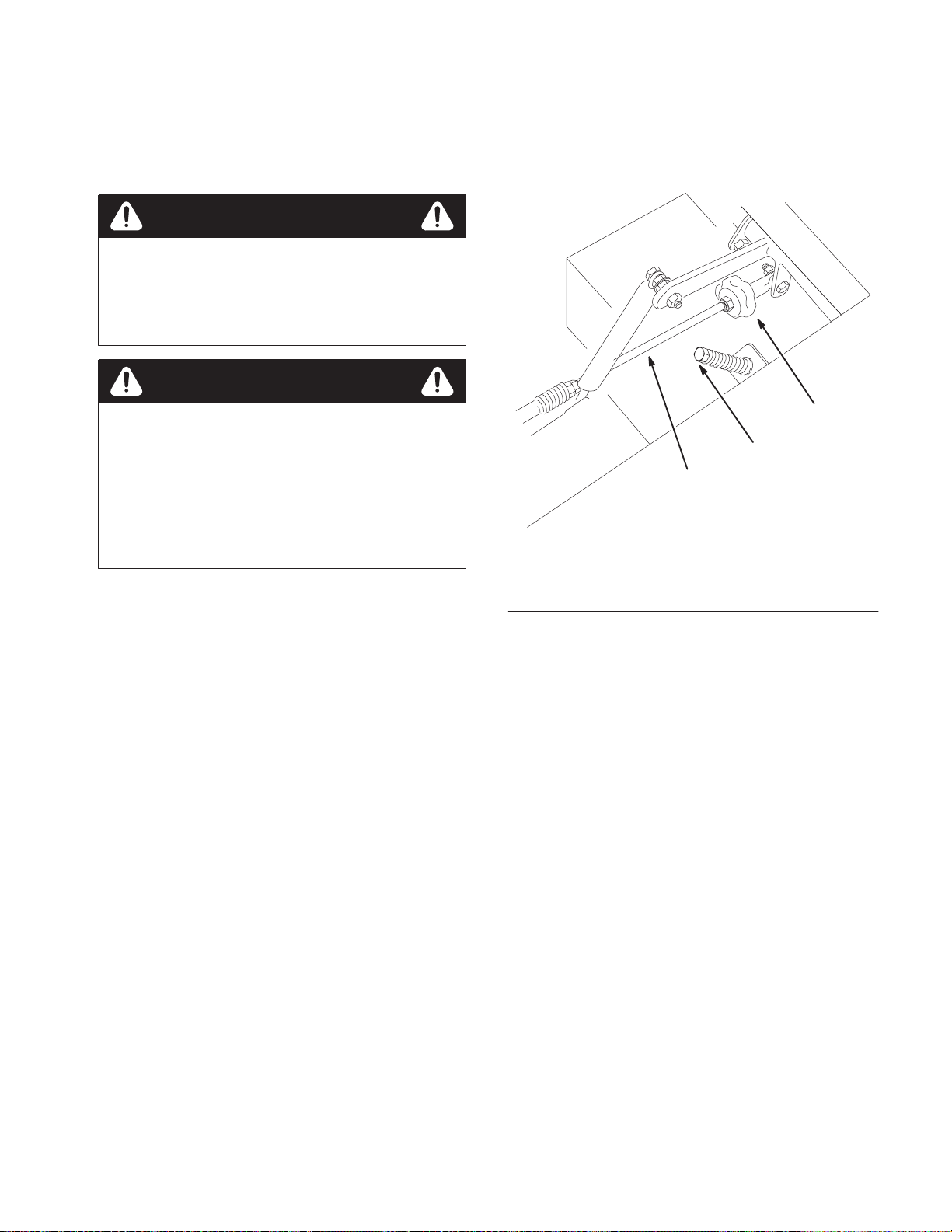
Setting the Hydraulic Pump
Neutral Position
3. Move motion control lever forward and reverse, then
back to neutral. Wheel must stop turning or slightly
creep in reverse.
Note: Adjust handle neutral first. That has to be correct
before the following adjustment can be made.
Danger
Mechanical or hydraulic jacks may fail to support
machine and cause a serious injury.
• Use jack stand when supporting machine.
• Do not use hydraulic jacks.
Warning
Engine must be running so motion control
adjustment can be performed. Contact with
moving parts or hot surfaces may cause personal
injury.
Keep hands, feet, face, clothing and other body
parts away from rotating parts, muffler and other
hot surfaces.
This adjustment must be made with drive wheels turning.
4. Open throttle to fast. Make sure wheel remains stopped
or slightly creeps in reverse, adjust if necessary.
1
3
2
m–6283
Figure 46
1. Tracking knob
2. Pump rod
3. Adjustment bolt
1. Raise the frame and block up the machine so drive
wheels can rotate freely.
2. Disconnect electrical connector from the seat safety
switch. Temporarily install a jumper wire across
terminals in the wiring harness connector.
3. Slide seat forward, disconnect prop rod and tilt seat
fully forward.
Setting the Left–hand Hydraulic Pump
Neutral Position
1. Start the engine, open throttle 1/2 way and release
parking brake. Refer to Starting and Stopping the
Engine, page 18.
Note: Motion control lever must be in neutral while
making any adjustments.
2. Adjust pump rod length by rotating the knob, in the
appropriate direction, until the wheel is still or slightly
creeping in reverse (Fig. 46).
Setting the Right–hand Hydraulic Pump
Neutral Position
1. Loosen the locknuts at the ball joints on pump control
rod (Fig. 45).
2. Start the engine, open throttle 1/2 way and release
parking brake. Refer to Starting and Stopping the
Engine, page 18.
Note: Motion control lever must be in neutral while
making any adjustments.
Note: The front nut on the pump rod has left–hand threads.
3. Adjust pump rod length by rotating double nuts on rod,
in the appropriate direction, until wheel is still or
slightly creeps in reverse (Fig. 45).
4. Move motion control lever forward and reverse, then
back to neutral. Wheel must stop turning or slightly
creep in reverse.
5. Open throttle to fast. Make sure wheel remains stopped
or slightly creeps in reverse, re-adjust if necessary.
37
Page 38
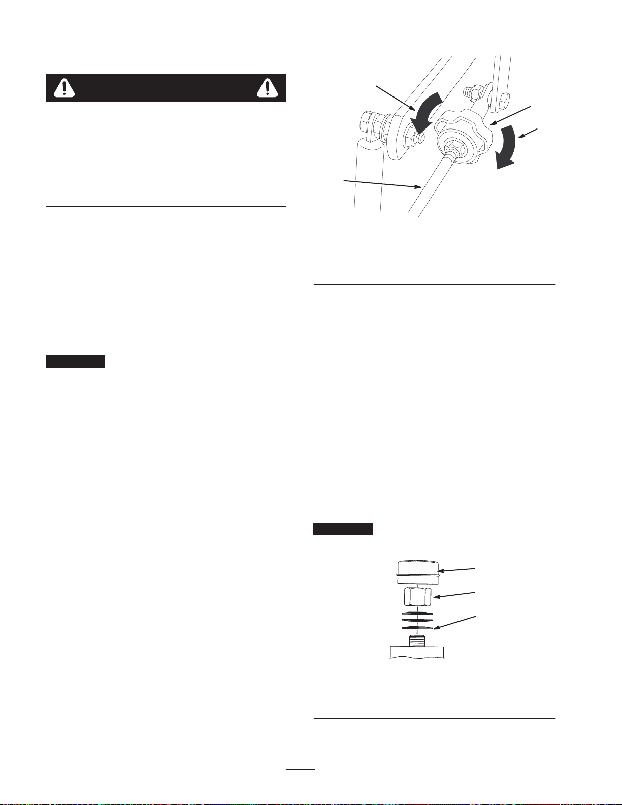
6. Tighten the nuts at the ball joints (Fig. 45).
Warning
Electrical system will not perform proper safety
shut off with jumper wire installed.
• Remove jumper wire from wire harness
connector and plug connector into seat switch
when adjustment is completed.
• Never operate this unit with jumper installed
and seat switch bypassed.
7. After both pump neutrals are set, shut off the machine.
8. Remove jumper wire from wire harness connector and
plug connector into seat switch.
9. Reinstall prop rod and lower the seat into position.
10.Remove the jack stands.
Adjusting the Tracking
The left–hand pump has a knob for adjusting the tracking.
Important Adjust the handle neutral and hydraulic
pump neutral before adjusting the tracking. Refer to
Adjusting the Handle Neutral on page 36 and Adjusting the
Hydraulic Pump Neutral on page 37.
2
3
4
1
m–6280
Figure 47
1. Pump rod
2. Turn this way to track left
3. Tracking knob
4. Turn this way to track
right
Adjusting the Caster Pivot
Bearing
Check after every 500 operating hours or at storage,
whichever occurs first.
1. Disengage the PTO, move the motion control levers to
the neutral locked position and set the parking brake.
1. Push both control levers forward the same distance.
2. Check if the machine pulls to one side. If it does, stop
the machine and set the parking brake.
3. Tip the seat up to access the tracking knob.
Note: Determine the left and right sides of the machine
from the normal operating position.
4. To make the machine go right, turn the knob towards
the rightside of the machine. Refer to figure 47.
5. To make the machine go left, turn the knob towards the
leftside of the machine. Refer to figure 47.
6. Repeat adjustment until the tracking is correct.
2. Stop the engine, remove the key, and wait for all
moving parts to stop before leaving the operating
position.
3. Remove the dust cap from the caster and tighten the
locknut (Fig. 48).
4. Tighten until the spring washers are flat and then back
off 1/4 turn to properly set the preload on the bearings
(Fig. 48).
Important Make sure that the spring washers are
installed correctly as shown in Figure 48.
3
2
1
m–4640
Figure 48
1. Spring washers
2. Locknut
3. Dust cap
38
Page 39

Checking the Wheel Hub
Leveling the Mower at Three
Slotted Nut
Check after every 500 operating hours.
The slotted nut needs to be torqued to 125 ft–lb (170 N⋅m).
1. Disengage the PTO, move the motion control levers to
the neutral locked position and set the parking brake.
2. Stop the engine, remove the key, and wait for all
moving parts to stop before leaving the operating
position.
3. Remove the cotter pin.
4. Torque the slotted nut to 125 ft–lb (170 N⋅m) (Fig. 49).
5. Check the distance from the bottom of the slot in the
nut to the inside edge of the hole. Two threads or less
should be showing (Fig. 49).
6. If more than two threads are showing, remove the nut
and install a washer between the hub and nut (Fig. 49).
7. Torque the slotted nut to 125 ft–lb (170 N⋅m) (Fig. 49).
8. Tighten the nut until the next set of slots line up with
the hole in the shaft (Fig. 49).
9. Install the cotter pin.
1
4
3
5
Positions
Important There are only three measuring positions
needed to level the mower.
Setting Up the Machine
1. Position mower on a flat surface.
2. Disengage the PTO, move the motion control levers to
the neutral locked position and set the parking brake.
3. Stop the engine, remove the key, and wait for all
moving parts to stop before leaving the operating
position.
4. Check tire pressure of all four tires. If needed, adjust to
13 psi (90 kPa)
5. Position the mower to the 3 inch (76 mm) height–of–cut
position.
6. Inspect the four chains. The chains need to have
tension.
Note: The rear chains need to be adjusted to the top of the
slot, where attached to the mower.
• If one rear chain is loose, lower (loosen) the front
support arm on the same side. Refer to Adjusting the
Front–to–Rear Mower Pitch on page 40.
• If one front chain is loose, raise (tighten) the front
support arm for that chain. Refer to Adjusting the
Front–to–Rear Mower Pitch on page 40.
2
1. Slotted nut
2. Two threads or less
showing
Figure 49
3. Hole in threaded shaft
4. Washer (if needed)
5. Slot
m–4638
Leveling the Mower Side–to–Side
1. Position the right blade front-to-rear (Fig. 50).
2. Measure the right blade at the B location (Fig. 50), from
a level surface to the cutting edge of the blade tip
(Fig. 51).
3. Record this measurement. This measurement needs to
be 3–1/8 to 3–1/4 inches.
4. Position the left blade front-to-rear (Fig. 50).
5. Measure the left blade at the C location (Fig. 50), from
a level surface to the cutting edge of the blade tip
(Fig. 51).
6. Record this measurement. This measurement needs to
be 3–1/8 to 3–1/4 inches.
39
Page 40
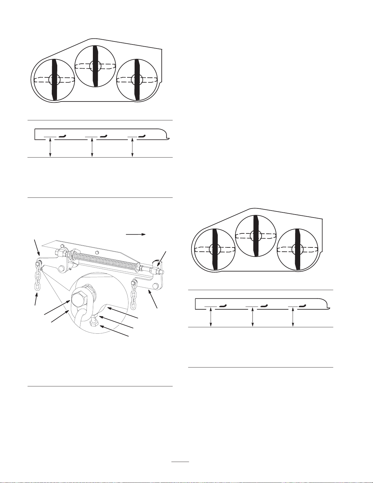
Front
9. Tighten the jam nut under the rear support arm and
tighten the bolt securing the chain to the rear support
arm.
10.Adjust the opposite side if needed.
Adjusting the Front–to–Rear Mower Pitch
C
B
m–1078
Figure 50
MEASURE FROM
CUTTING EDGE TO
A LEVEL SURFACE
m–2539
Figure 51
7. If the measurements at positions B or C are not correct,
loosen the bolt attaching the rear chain to the rear
support arm (Fig. 52).
2
Front
1. Position the right blade front-to-rear (Fig. 53).
2. Measure the right blade at the A location (Fig. 53), from
a level surface to the cutting edge of the blade tip
(Fig. 54).
3. Record this measurement.
4. Measure the right blade at the B location (Fig. 53), from
a level surface to the cutting edge of the blade tip
(Fig. 54).
5. Record this measurement.
6. The mower blade should be a 1/4 to 3/8 inch
(6 to 10 mm) lower at position A than at position B
(Fig. 53). If it is not correct, proceed to the following
steps.
Front
A
6
B
m–1078
1
3
1
2
4
5
7
m–6920
Figure 52
1. Rear chain
2. Rear support arm
3. Bolt
4. Jam Nut
5. Adjustment bolt
6. Front swivel
7. Front support arm
8. Loosen the jam nut under the rear support arm and
adjust the adjustment bolt to get a measurement of
3–1/8 to 3–1/4 inches.
Note: It is recommended that both sides of the mower are
adjusted the same distance.
Figure 53
MEASURE FROM
CUTTING EDGE TO
A LEVEL SURFACE
m–2539
Figure 54
Note: Both of the front swivels need to be adjusted the
same amount to maintain equal chain tension.
7. Loosen the front swivel jam nuts, at the front of the
right and left swivels, approximately a 1/2 inch
(13 mm) (Fig. 55).
8. Adjust the lift nuts on both the left and the right side of
the machine to achieve 1/4 to 3/8 inch (6 to 10 mm)
lower in front at A than in the rear at B (Fig. 55).
40
Page 41
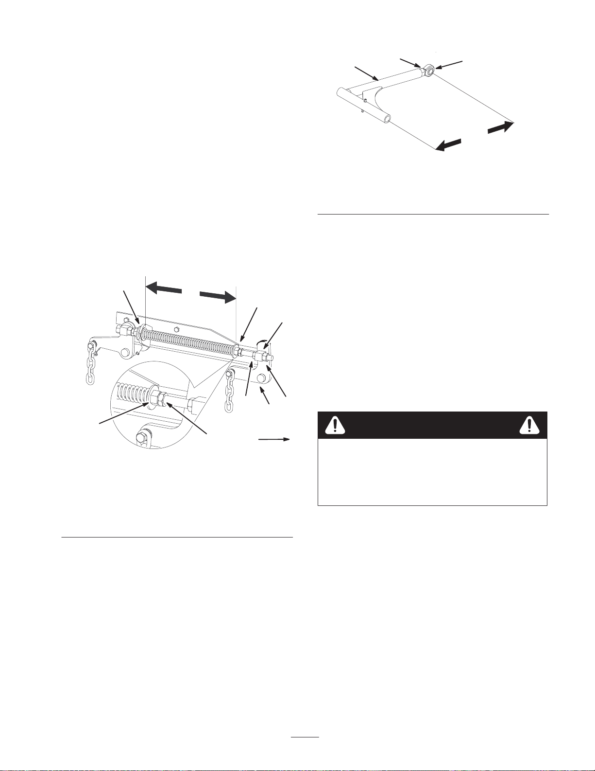
9. Tighten both swivel jam nuts against the front swivel to
lock the height.
10.Check to make sure there is equal tension on the chains
and adjust again if needed.
Adjusting the Compression Spring
1. Raise the mower lift lever to the transport position
(Fig. 55).
2. Check the distance between the two large washers, it
needs to be 10–1/4 inches (260 mm) (Fig. 55).
3. Adjust this distance, by loosening the spring jam nut
and turning the nut in front of each spring (Fig. 55).
Turning the nut clockwise will shorten the spring;
counter–clockwise will lengthen the spring.
4. Lock the nut into position by tightening the spring jam
nut (Fig. 55).
1
3
4
2
Figure 56
1. Push arm
2. 15-5/16 inch (389 mm)
nominal
3. Jam nut
4. Ball joint
Cleaning Under the Mower
Remove grass build up under the deck daily.
m–6273
8
1
8
6
7
2
3
m–6921
Front
Figure 55
1. 10–1/4 inch (260 mm)
between the large
washers
2. Front nut
3. Spring jam nut
4. Front swivel
5. Swivel jam nut
6. Lift nut
7. Front support arm
8. Large washer
Adjusting the Push Arms
If needed, adjust the push arms to increase or decrease the
mower belt tension.
1. To adjust the push arms, loosen the jam nut and rotate
the ball joint counterclockwise, one turn at a
time.(Fig. 56).
2. Adjust each side the same amount. Each push arm
should have a nominal length of 15-5/16 inch (389 mm)
(Fig. 56).
Note: Increase the tension by lengthening the push arms
and decrease the tension by shortening the push arms.
1. Position the mower on a flat surface.
2. Disengage the PTO, move the motion control levers to
4
the neutral locked position and set the parking brake.
3. Stop the engine, remove the key, and wait for all
moving parts to stop before leaving the operating
position.
4. Raise the deck to the transport position.
5. Lift the front of the unit and support the unit using jack
5
stands.
Danger
Mechanical or hydraulic jacks may fail to support
machine and cause a serious injury.
• Use jack stand when supporting machine.
• Do not use hydraulic jacks.
Inspecting the Belts
Inspect all belts every 50 hours.
Check belts for cracks, frayed edges, burn marks, or any
other damage. Replace damaged belts.
Replacing the Mower Belt
Squealing when the belt is rotating, blades slipping when
cutting grass, frayed belt edges, burn marks, and cracks are
signs of a worn deck belt. Replace the deck belt if any of
these conditions are evident.
1. Disengage the PTO, move the motion control levers to
the neutral locked position and set the parking brake.
41
Page 42
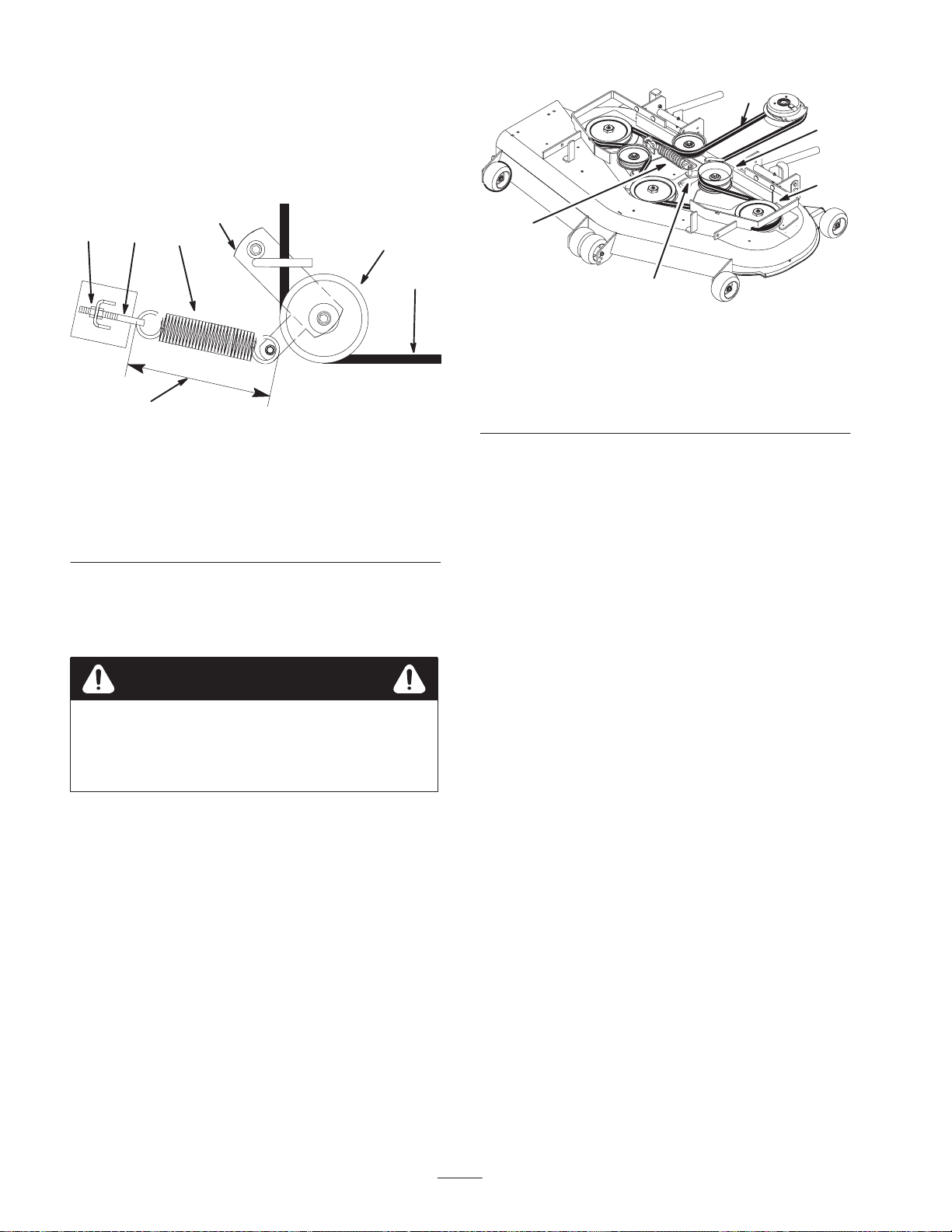
2. Stop the engine, remove the key, and wait for all
moving parts to stop before leaving the operating
position.
3. Remove the belt covers over the outside spindles.
1
5
4. Loosen the outer nut on the spring eye bolt (Fig. 57).
14
3
5
2
7
6
M–4197
Figure 57
Top View
1. Outer nut
2. Idler pulley
3. Idler arm
4. Spring eye bolt
5. Spring
6. 9-3/8 ± 1/8 inch
(238 ± 3 mm)
7. Deck belt
5. Remove the belt. Start at the outside pulley and rotate
the belt off (Fig. 58).
Note: Dot not remove the spring from the eye bolt.
Caution
3
4
2
M–4159
Figure 58
Top View
1. Deck belt
2. Idler arm
3. Outside pulley
4. Spring
5. Idler pulley
Replacing the Pump Drive Belt
Check the pump drive belt for wear after every 50 hours of
operation.
1. Remove the deck belt first; refer to Replacing the Deck
Belt, page 41.
2. Remove the bolt from the clutch strap and unplug the
clutch electrical wire (Fig. 59).
3. Pull the spring loaded idler to the side. Remove the
traction belt from the engine and hydro pump pulleys
(Fig. 59).
Spring is under tension when installed and can
cause personal injury.
Do not remove spring from spring eye bolt.
6. Remove spring loaded idler pulley (Fig. 57).
7. Route the new belt through the idler arm (Fig. 57).
8. Install the idler pulley and route the belt onto the other
pulleys (Fig. 58).
9. Tighten the outer nut on the spring eye bolt (Fig. 57).
Note: Check the spring length. The spring should measure
9-3/8 ± 1/8 inch (238 ±3 mm) when installed. Adjust it if it
does not (Fig. 57).
10.Install the belt covers over the outside spindles.
4. Install the new belt around the engine and hydro pump
pulleys (Fig. 59).
5. Pull the spring loaded idler to the side and align the
belt. Release pressure on the spring loaded idler
(Fig. 59).
6. Install the deck belt.
42
Page 43
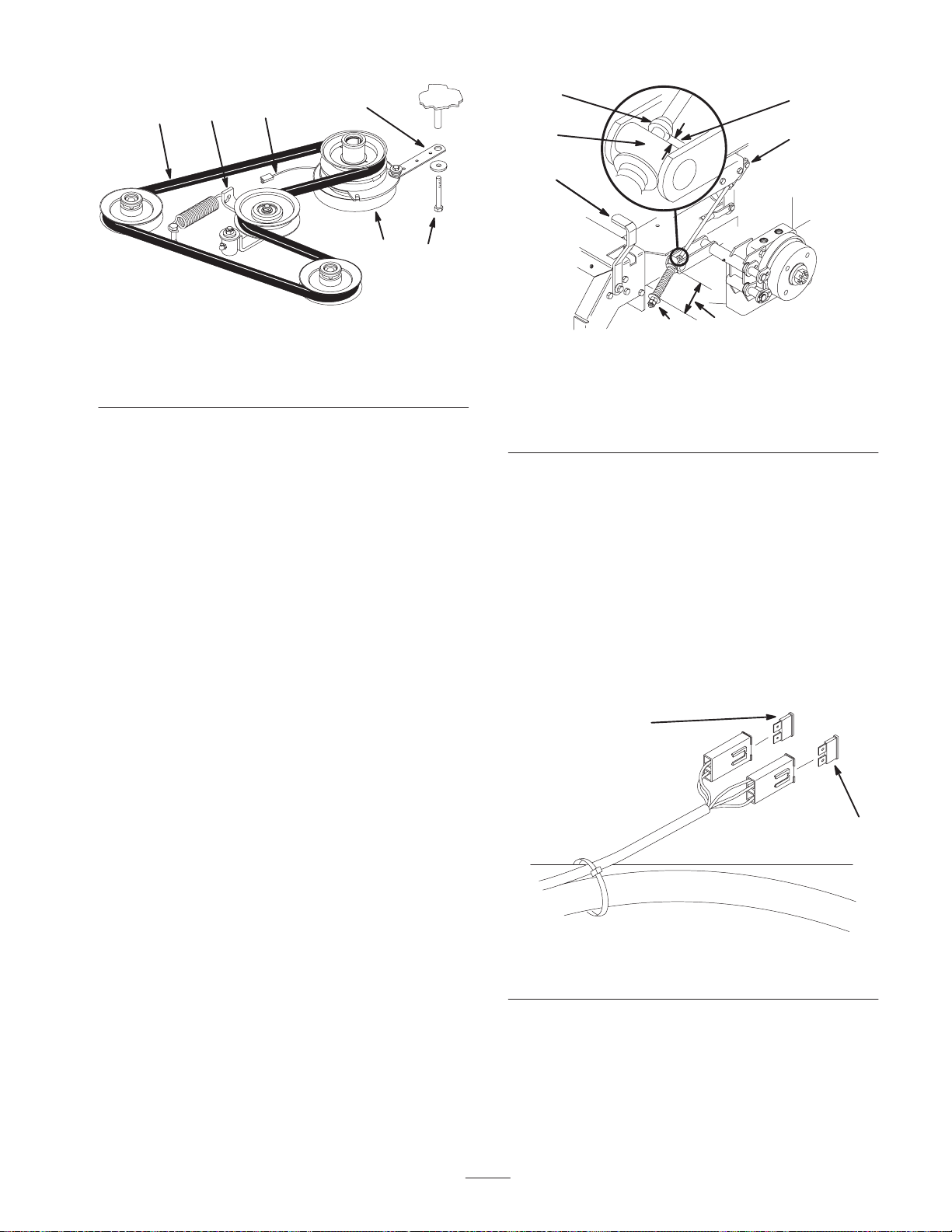
4
5
3
1
6
Figure 59
1. Clutch strap
2. Bolt
3. Clutch electrical wire
4. Belt
5. Idler
6. Clutch
Adjusting the Parking Brake
2
m–4119
4
7
11
1. Brake lever
2. Spring, 2-3/4 inch
(74 mm)
3. Adjusting nuts
3
Figure 60
4. Collar on brake rod
5. 3/16–1/4 inch (5–7 mm)
6. Jam nut and yoke
7. Trunnion
5
6
2
M–4120
Check the parking brake for proper adjustment.
1. Disengage the brake lever (lever down).
2. Measure the length of the spring. The measurement
should be 2-3/4 inch (74 mm) between the washers
(Fig. 60).
3. If an adjustment is necessary, loosen the jam nut below
the spring and tighten the nut directly below the yoke
(Fig. 60). Turn the nut until the correct measurement is
obtained. Tighten the two nuts together and repeat on
the opposite side of the unit.
4. Turn the nuts clockwise to shorten the spring length and
turn them counterclockwise to lengthen the spring.
5. Engage the parking brake, lever up.
6. Measure the distance between the trunnion roller and
the collar on the brake rod. The measurement should be
3/16–1/4 inch (5–7 mm) (Fig. 60).
7. If an adjustment is necessary, loosen the jam nut
directly below the yoke. Turn the bottom adjusting nuts
until the correct measurement is obtained (Fig. 60).
Tighten the jam nut at the yoke.
Servicing the Fuses
The electrical system is protected by fuses. It requires no
maintenance; however, if a fuse blows, check the
component/circuit for a malfunction or short.
Fuse: Main F1—20 amp, blade-type
Alternator F2—20 amp, blade-type
1. Raise the seat to gain access to the fuse holder (Fig. 61).
2. To replace the fuses, pull out on the fuse to remove it
(Fig. 61).
2
1
m–3653
Figure 61
1. Main—20 amp 2. Alternator—20 amp
43
Page 44
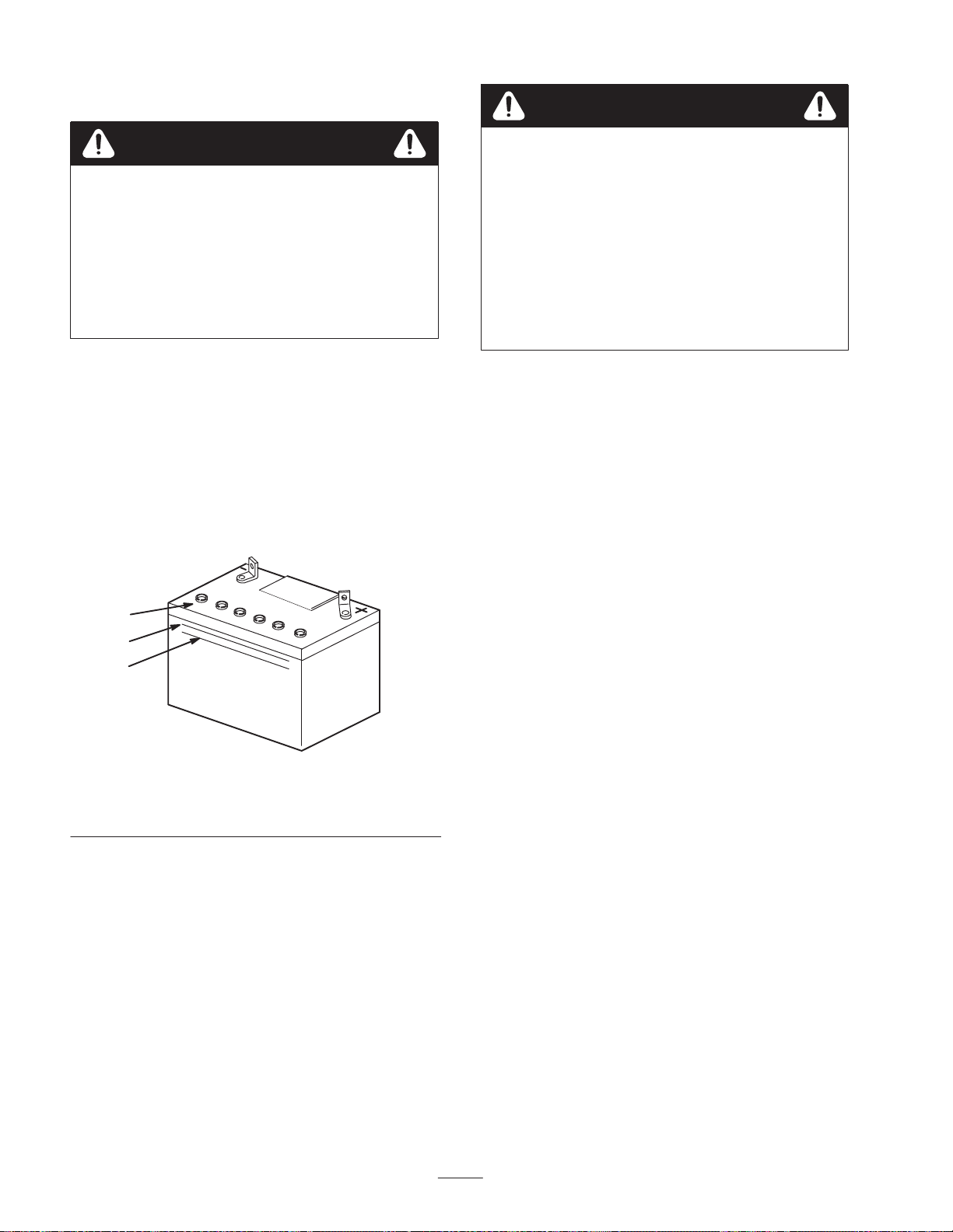
Servicing the Battery
Danger
Warning
CALIFORNIA
Proposition 65 Warning
Battery posts, terminals, and related accessories
contain lead and lead compounds, chemicals
known to the State of California to cause cancer
and reproductive harm. Wash hands after
handling.
Checking Electrolyte Level
1. With the engine off, open the hood to locate the battery.
2. Look at the side of the battery. The electrolyte must be
up to the upper line (Fig. 62). Do not allow the
electrolyte to get below the lower line (Fig. 62).
3. If the electrolyte is low, add the required amount of
distilled water; refer to Adding Water to the Battery,
page 45.
Battery electrolyte contains sulfuric acid which is a
deadly poison and causes severe burns.
• Do not drink electrolyte and avoid contact with
skin, eyes or clothing. Wear safety glasses to
shield your eyes and robber gloves to protect
your hands.
• Fill the battery where clean water is always
available for flushing the skin.
• Follow all instructions and comply with all
safety messages on the electrolyte container.
Installing the Battery
1. Position battery in tray with terminal posts toward the
engine (Fig. 63).
2. First, install the positive (red) battery cable to positive
(+) battery terminal.
3. Then install negative battery cable and ground wire to
the negative (–) battery terminal.
4. Secure cables with 2 bolts (1/4 x 3/4 inch), 2 washers
(1/4 inch), and 2 locknuts (1/4 inch) (Fig. 63).
1
2
3
1. Filler caps
2. Upper line
5. Slide the red terminal boot onto the positive (red)
battery post.
6. Secure battery with J-bolts, hold down clamp and
2 washers (1/4 inch), and 2 wing nuts (1/4 inch)
(Fig. 63).
m–5004
Figure 62
3. Lower line
44
Page 45
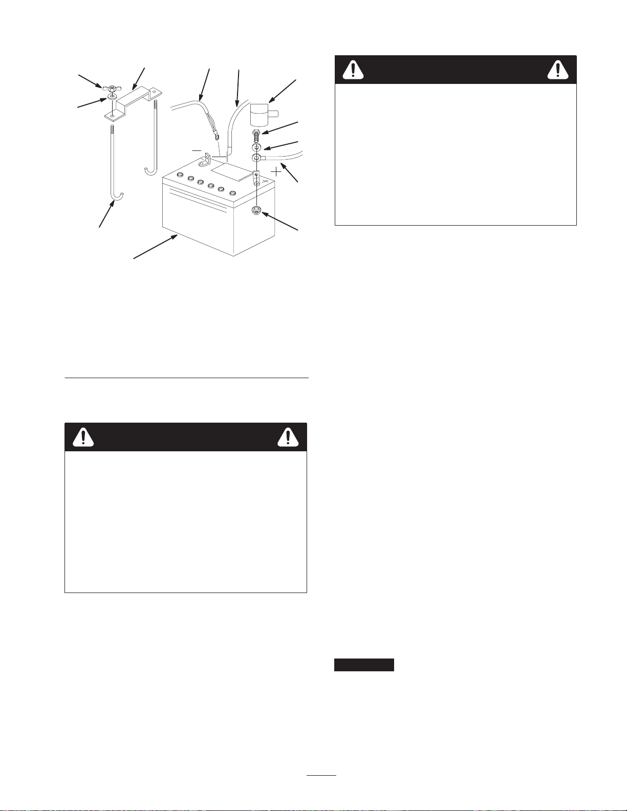
6
7
3
8
11
7
9 5
4
2
Warning
Incorrect battery cable routing could damage the
machine and cables causing sparks. Sparks can
cause the battery gasses to explode, resulting in
personal injury.
• Always Disconnect the negative (black) battery
cable before disconnecting the positive (red)
cable.
• Always Reconnect the positive (red) battery
cable before reconnecting the negative (black)
cable.
10
1
Figure 63
1. Battery
2. Terminal boot
3. Positive battery cable
4. Negative battery cable
5. Ground wire
6. Bolt, 1/4 x 3/4 inch
7. Washer, 1/4 inch
8. Locknut, 1/4 inch
9. Battery clamp
10. J-bolts
11. Wing nut, 1/4 inch
Removing the Battery
Warning
Battery terminals or metal tools could short
against metal machine components causing sparks.
Sparks can cause the battery gasses to explode,
resulting in personal injury.
• When removing or installing the battery, do not
allow the battery terminals to touch any metal
parts of the machine.
• Do not allow metal tools to short between the
battery terminals and metal parts of the
machine.
m–5598
1. Disengage the PTO, move the motion control levers to
the neutral locked position and set the parking brake.
2. Stop the engine, remove the key, and wait for all
moving parts to stop before leaving the operating
position.
3. Tilt seat up.
4. First disconnect the negative battery cable and ground
wire from the negative (–) battery terminal (Fig. 63).
5. Slide the red terminal boot off the positive (red) battery
terminal. Then remove positive (red) battery cable
(Fig. 63).
6. Remove both wing nuts (1/4 inch) securing the battery
clamp (Fig. 63).
7. Remove the battery.
Adding Water to the Battery
Note: Never fill the battery with distilled water while the
battery installed in the machine. Electrolyte could be
spilled on other parts and cause corrosion.
The best time to add distilled water to the battery is just
before you operate the machine. This lets the water mix
thoroughly with the electrolyte solution.
1. Remove the battery from the machine.
2. Clean the top of the battery with a paper towel.
3. Remove the vent caps from the battery (Fig. 62).
4. Slowly pour distilled water into each battery cell until
the level is up to the upper line (Fig. 62) on the battery
case.
Important Do not overfill the battery because
electrolyte (sulfuric acid) can cause severe corrosion and
damage to the chassis.
45
Page 46
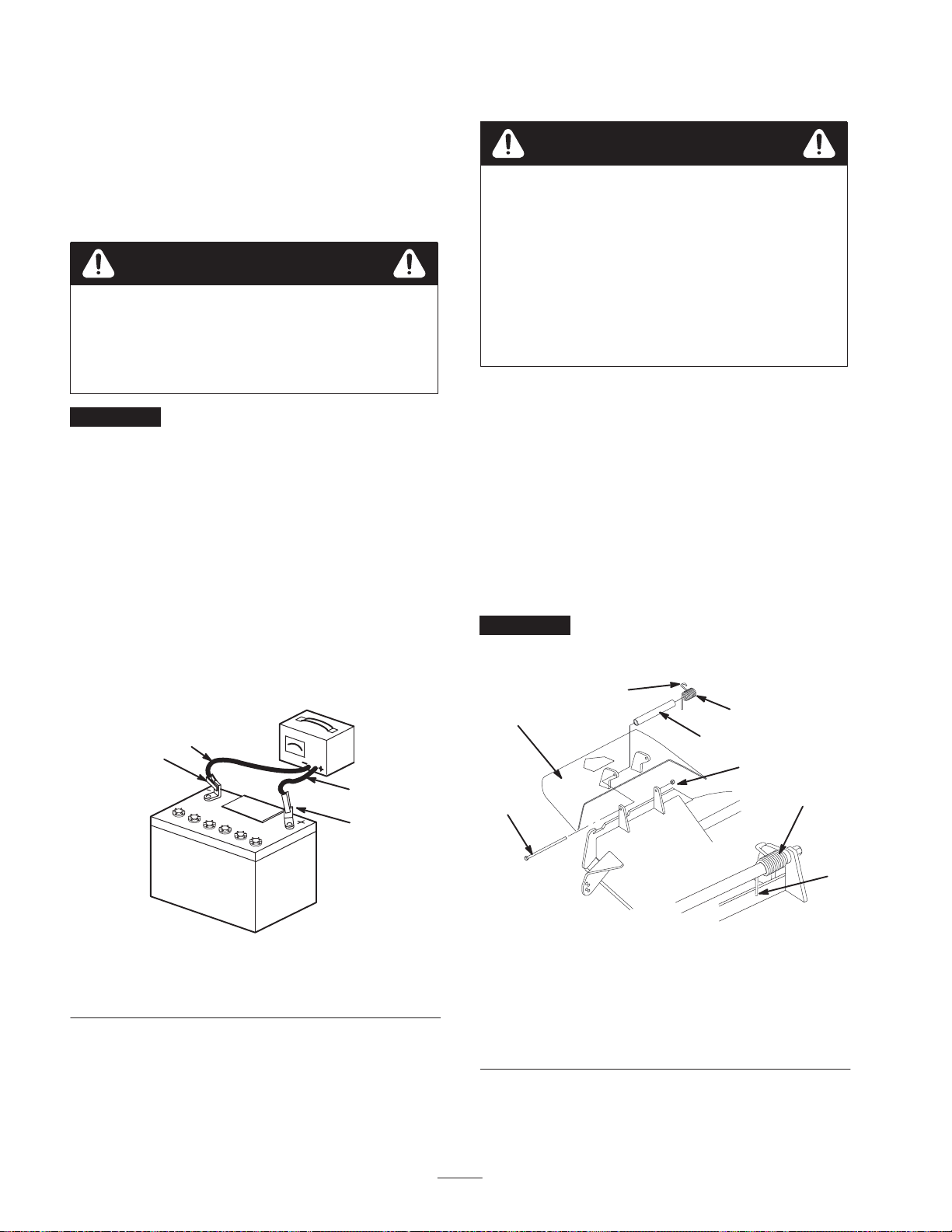
5. Wait five to ten minutes after filling the battery cells.
Add distilled water, if necessary, until the electrolyte
level is up to the upper line (Fig. 62) on the battery
case.
6. Reinstall battery vent caps.
Charging the Battery
Warning
Charging the battery produces gasses that can
explode.
Never smoke near the battery and keep sparks and
flames away from battery.
Important Always keep the battery fully charged
(1.265 specific gravity). This is especially important to
prevent battery damage when the temperature is below
32°F (0°C).
1. Remove the battery from the chassis; refer to Removing
the Battery, page 45.
2. Check the electrolyte level; refer to Checking
Electrolyte Level, page 44.
3. Make sure the filler caps are installed in battery. Charge
battery for 10 to 15 minutes at 25 to 30 amps or
30 minutes at 4–6 amps.
4. When the battery is fully charged, unplug the charger
from the electrical outlet, then disconnect the charger
leads from the battery posts (Fig. 64).
4
2
Replacing the Grass Deflector
Warning
An uncovered discharge opening could allow the
lawn mower to throw objects in the operator’s or
bystander’s direction and result in serious injury.
Also, contact with the blade could occur.
• Never operate the lawn mower unless you install
a cover plate, a mulch plate, or a grass chute
and catcher.
• Make sure the grass deflector is in the down
position.
1. Remove the locknut, bolt, spring, and spacer holding
the deflector to the pivot brackets (Fig. 65). Remove the
damaged or worn grass deflector.
2. Place the spacer and spring onto the grass deflector.
Place the straight end of the spring behind the deck
edge.
Note: Make sure that the straight end of the spring is
installed behind the deck edge before installing the bolt as
shown in Figure 65.
3. Install the bolt and nut. Place the hook end of the spring
around the grass deflector (Fig. 65).
Important The grass deflector must be able to lower
down into position. Lift the deflector up to test that it
lowers into the full down position.
8
6
4
2
3
3
1
Figure 64
1. Positive Battery Post
2. Negative Battery Post
3. Red (+) Charger Lead
4. Black (–) Charger Lead
5. Install the battery in the machine and connect the
battery cables; refer to Installing the Battery on page 44.
Note: Do not run the machine with the battery
disconnected, electrical damage may occur.
m–4970
1
1. Bolt
2. Spacer
3. Locknut
4. Spring
5. Spring installed
46
5
7
m–5037
Figure 65
6. Grass deflector
7. Place behind deck edge
before installing bolt
8. Hook end of spring
Page 47

Waste Disposal
Engine oil, hydraulic oil, and engine coolant are pollutants
to the environment. Dispose of these according to your
state and local regulations.
Caution
The mercury contained in the tilt switch is
poisonous and exposure to mercury can cause
severe illness.
Mercury Tilt Switch
The tilt switch on this unit is located under the seat. Tilt the
seat up to gain access.
The tilt switch on this unit contains mercury, a hazardous
material. Mercury that is outside a sealed container
vaporizes at room temperature. The vapors are harmful.
Mercury can be absorbed through the skin. Do not attempt
to open or repair this switch.
A very small amount of mercury is contained in a
hermetically sealed body. The steel switch is then potted in
a hard epoxy in a plastic case. It is unlikely that the
mercury will ever escape from the enclosure. These high
performance and reliable inexpensive switches are
recyclable.
Mercury is an important and beneficial compound but
requires special care in handling and disposal. When used
and managed properly, mercury is not a threat to people or
the environment. This information is presented to users so
that they are aware that these switches contain mercury and
will apply sound disposal practices when these devices
reach their normal end of life or are damaged.
Mercury Tilt Switch Disposal
• Never attempt to open or repair the tilt
switch.
• Avoid contact with the mercury.
Several states have passed laws concerning the disposal of
devices containing mercury. In all the remaining states it is
advisable to follow similar procedures. The laws state that
these sealed devices contain mercury and should not be
placed in the garbage until the mercury is removed and
reused, recycled, or otherwise managed to ensure that it
does not become part of solid waste or waters. Management
and disposal practices must be within relevant federal,
state, or local laws.
Return the switch to your Toro dealer if it is faulty and is
being replaced or if the unit containing the switch is no
longer operating and is being scrapped. If the switch is
damaged or broken open, use extreme caution in handling.
Call your local waste management authority or Toro
Customer Service for instructions.
47
Page 48
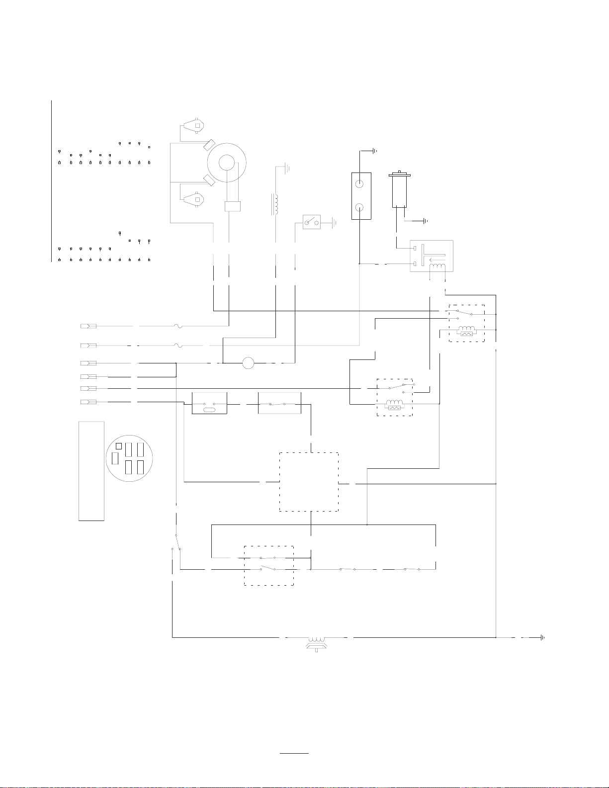
Wiring Diagram
TAN
RED
PINK
T
R
PK
WIRE COLOR CODES
BLUE
BROWN
BLACK
BU
BN
BK
I A
Y B
SW1
(IGNITION)
X S
WHITE
VIOLET
W
VIO
GREY
GREEN
GN
GY
YELLOW
PINK/BLACK
Y
PK/BK
DK.GN
ORANGE
ORANGE/BLACK
DARK GREEN/WHITE DARK GREEN
OR
OR/BK
DK.GN/W
DARK BLUE
DK.BU
LIGHT BLUE
LIGHT GREEN BLACK/RED
LT.GN BK/R
LT.BU
VIO
OR
OR R
Y
T
IGNITION
SPARK PLUG SPARK PLUG
F2
25A
F1
30A
MODULES
MAG
W
R
OR
AC
REG
VIO
HOUR
AC
METER
GY
FUEL
SOLINIOD
FUEL
OR
–+
DK.BU
OIL
DK.BU
OIL
SWITCH
–+
Y
GND
BATTERY
STARTER
R
DK.GN/W
1
235
+
–
GND
R
SOLINOID
BK
OR/BKOR/BK
3
W
DK.GN
4
1
4
2
5
BK
K1
(KILL RELAY)
I
B
S
X
A
Y
KEY SWITCH PN 88–9830
OFF NO CONNECTION
ON B I A AND X Y
START B I S
KEY SW
TERMINAL VIEW FROM
BACK OF SWITCH
SW2
(PTO)
GY
SW7
OR
SHOWN IN
(TILT SW)
SWITCH OPENS
WHEN TILTED
PAST 60 DEGREES
FROM VERTICAL
OFF POSITION
PK/BK
DK.GN
SW3
(BRAKE)
SW6
T
(SEAT SW)
SHOWN WITH
OPERATOR
IN SEAT
P1–A
DELAY MODULE
100–6186
DISENGAGED
SHOWN WITH
PARK BRAKE
GY
LT.BU
BN
P1–C P2–C
LT.BU
PTO
P1–B
CLUTCH
BK
SHOWN WITH
LEVER IN
NEUTRAL
POSITION
SW4
(NEUTRAL)
BK
LT.GN
K2
(START RELAY)
SHOWN WITH
LEVER IN
SW5
DK.GN
NEUTRAL
POSITION
(NEUTRAL)
GND
BK
48
Page 49

Cleaning and Storage
1. Disengage the power take off (PTO), set the parking
brake and turn the ignition key to off. Remove spark
plug wire. Remove the key.
2. Remove grass clippings, dirt, and grime from the
external parts of the entire machine, especially the
engine and hydraulic system. Clean dirt and chaff from
the outside of the engine’s cylinder head fins and
blower housing.
Important You can wash the machine with mild
detergent and water. Do not pressure wash the machine.
Avoid excessive use of water, especially near the control
panel, engine, hydraulic pumps and motors.
3. Service the air cleaner; refer to Servicing the Air
Cleaner, page 28.
4. Grease and oil the machine; refer to Greasing and
Lubrication, page 32.
5. Change the crankcase oil and filter; refer to Servicing
the Engine Oil, page 29.
6. Change the hydraulic filter; refer to Servicing the
Hydraulic System, page 34.
7. Check the tire pressure; refer to Checking the Tire
Pressure, page 33.
8. Charge the battery; refer to Servicing the Battery
page 44.
9. Scrape any heavy buildup of grass and dirt from the
underside of the mower, then wash the mower with a
garden hose.
Note: Run the machine with the PTO engaged and the
engine at high idle for 2 to 5 minutes after washing.
10.Check the condition of the blades. Refer to Servicing
the Cutting Blades on page 26.
A. Add a petroleum based stabilizer/conditioner to fuel
in the tank. Follow mixing instructions from
stabilizer manufacture. Do not use an alcohol
based stabilizer (ethanol or methanol).
Note: A fuel stabilizer/conditioner is most effective when
mixed with fresh gasoline and used at all times.
B. Run engine to distribute conditioned fuel through
the fuel system (5 minutes).
C. Stop engine, allow to cool and drain the fuel tank;
refer to Servicing the Fuel Tank, page 32.
D. Restart engine and run it until it stops.
E. Choke the engine. Start and run engine until it will
not start.
F. Dispose of fuel properly. Recycle as per local codes.
Important Do not store stabilizer/conditioned gasoline
over 90 days.
12.Remove the spark plug(s) and check its condition; refer
to Servicing the Spark Plug, page 31. With the spark
plug(s) removed from the engine, pour two tablespoons
of engine oil into the spark plug hole. Now use the
starter to crank the engine and distribute the oil inside
the cylinder. Install the spark plug(s). Do not install the
wire on the spark plug(s).
13.Check and tighten all bolts, nuts, and screws. Repair or
replace any part that is damaged or defective.
14.Paint all scratched or bare metal surfaces. Paint is
available from your Authorized Service Dealer.
15.Store the machine in a clean, dry garage or storage area.
Remove the key from the ignition switch and keep it in
a memorable place out of reach of children or other
unauthorized users. Cover the machine to protect it and
keep it clean.
11. Prepare the machine for storage when non–use occurs
over 30 days. Prepare machine for storage as follows.
49
Page 50

Troubleshooting
g
g
g
Problem Possible Causes Corrective Action
Starter does not crank.
Engine will not start, starts hard, or
fails to keep running.
1. Blade control (PTO) is
engaged.
2. Parking brake is not on. 2. Set parking brake.
3. Operator is not seated. 3. Sit on the seat.
4. Battery is dead. 4. Charge the battery.
5. Electrical connections are
corroded or loose.
6. Fuse is blown. 6. Replace fuse.
7. Relay or switch is defective. 7. Contact Authorized Service
1. Fuel tank is empty. 1. Fill fuel tank with gasoline.
2. Fuel valve turned off. 2. Open fuel valve.
3. Choke is not on. 3. Move choke lever to on.
4. Air cleaner is dirty. 4. Clean or replace air cleaner
5. Spark plug wires are loose or
disconnected.
6. Spark plugs are pitted, fouled,
or gap is incorrect.
1. Move blade control (PTO) to
Disengaged.
5. Check electrical connections
for good contact.
Dealer.
element.
5. Install wires on spark plug.
6. Install new, correctly gapped
spark plugs.
Engine loses power.
Engine overheats.
7. Dirt in fuel filter. 7. Replace fuel filter.
8. Dirt, water, or stale fuel is in
fuel system.
1. Engine load is excessive. 1. Reduce ground speed.
2. Air cleaner is dirty. 2. Clean air cleaner element.
3. Oil level in crankcase is low. 3. Add oil to crankcase.
4. Cooling fins and air passages
under engine blower housing
are plugged.
5. Spark plugs are pitted, fouled,
or gap is incorrect.
6. Dirt in fuel filter. 6. Replace fuel filter.
7. Dirt, water, or stale fuel is in
fuel system.
1. Engine load is excessive. 1. Reduce ground speed.
2. Oil level in crankcase is low. 2. Add oil to crankcase.
3. Cooling fins and air passages
under engine blower housing
are plugged.
8. Contact Authorized Service
Dealer.
4. Remove obstruction from
cooling fins and air passages.
5. Install new, correctly gapped
spark plugs.
7. Contact Authorized Service
Dealer.
3. Remove obstruction from
cooling fins and air passages.
50
Page 51

Problem Corrective ActionPossible Causes
gg
Machine does not drive.
Abnormal vibration.
1. Traction belt is worn, loose or
broken.
2. Traction belt is off pulley. 2. Contact Authorized Service
3. Hydro fluid level low. 3. Add hydro fluid to reservoir.
1. Engine mounting bolts are
loose.
2. Loose engine pulley, idler
pulley, or blade pulley.
3. Engine pulley is damaged. 3. Contact Authorized Service
4. Cutting blade(s) is/are bent or
unbalanced.
5. Blade mounting bolt is loose. 5. Tighten blade mounting bolt.
6. Engine mounting bolts are
loose.
7. Loose engine pulley, idler
pulley, or blade pulley.
8. Engine pulley is damaged. 8. Contact Authorized Service
1. Contact Authorized Service
Dealer.
Dealer.
1. Tighten engine mounting bolts.
2. Tighten the appropriate pulley.
Dealer.
4. Install new cutting blade(s).
6. Tighten engine mounting bolts.
7. Tighten the appropriate pulley.
Dealer.
Uneven cutting height.
Blades do not rotate.
9. Blade spindle bent. 9. Contact Authorized Service
Dealer.
1. Blade(s) not sharp. 1. Sharpen blade(s).
2. Cutting blade(s) is/are bent. 2. Install new cutting blade(s).
3. Mower is not level. 3. Level mower from side-to-side
and front-to-rear.
4. Gage wheel not set correctly. 4. Adjust gage wheel height.
5. Underside of mower is dirty. 5. Clean the underside of the
mower.
6. Tire pressure is incorrect. 6. Adjust tire pressure.
7. Blade spindle bent. 7. Contact Authorized Service
Dealer.
1. Mower belt is off the pulley. 1. Install the mower belt and
check the adjusting plate, idler
arm and spring, and belt guides
for correct position
2. Mower belt is worn, loose or
broken.
3. Electric clutch does not
engage.
2. Install a new mower belt.
3. Contact Authorized Service
Dealer.
4. Electric clutch is worn. 4. Contact Authorized Service
Dealer.
51
Page 52

LCE
The Toro Total Coverage Guarantee
A Limited Warranty
Conditions and Products Covered
The Toro Company and its affiliate, Toro Warranty Company,
pursuant to an agreement between them, jointly promise to repair
the listed Toro Products if defective in materials or workmanship.
The following time periods apply from the date of purchase:
Products
• All Products 1 year
• All Spindles 2 years parts and labor;
• Engines/Hydraulic Systems* on
the following:
Outfront and Mid-Mount Z’s
ProLine Mid-Size Mowers
Groundsmaster
Backpack Blowers
• Deck Shells (36″–72″) on the
following:
ProLine Mid-Size Mowers
Mid-Mount Z’s
• Electric Clutch on 200 Series
Mid-Mount Z’s
This warranty includes the cost of parts and labor, but you must
pay transportation costs.
This warranty applies to:
• Outfront and Mid-Mount Z’s
• ProLine Mid-Size Mowers
• Groundsmaster Riding Mowers
• Turf Maintenance Equipment
• Debris Management Equipment
* Some engines used on Toro LCE Products are warranted by the
engine manufacturer.
Riding Mowers
Warranty Period
third year, parts only
2 years
2 years
2 years
Instructions for Obtaining Warranty Service
If you think that your T oro Product contains a defect in materials or
workmanship, follow this procedure:
1. Contact any Toro Authorized or Master Service Dealer to
arrange service at their dealership. To locate a dealer
convenient to you, access our website at www.Toro.com. U.S.
Customers may also call 800-348-2424.
2. Bring the product and your proof of purchase (sales receipt) to
the Service Dealer.
If for any reason you are dissatisfied with the Service Dealer’s
analysis or with the assistance provided, contact us at:
LCB Customer Service Department
Toro Warranty Company
8111 Lyndale Avenue South
Bloomington, MN 55420-1196
888-577-7466 (U.S. customers)
877-484-9255 (Canada customers)
You must maintain your Toro Product by following the maintenance
procedures described in the operator’s manual. Such routine
maintenance, whether performed by a dealer or by you, is at your
expense.
There is no other express warranty except for special emission
system coverage on some products. This express warranty does
not cover the following:
• Cost of regular maintenance service or parts, such as filters,
fuel, lubricants, tune-up parts, blade sharpening, brake and
clutch adjustments.
• Any product or part which has been altered or misused or
required replacement or repair due to normal wear, accidents,
or lack of proper maintenance.
• Repairs necessary due to improper fuel, contaminants in the
fuel system, or failure to properly prepare the fuel system prior
to any period of non-use over three months.
• Pickup and delivery charges.
All repairs covered by this warranty must be performed by an
Authorized T oro Service Dealer using Toro approved replacement
parts.
Repair by an Authorized Toro Service Dealer is your sole remedy
under this warranty.
Neither The Toro Company nor Toro Warranty Company is liable
for indirect, incidental or consequential damages in connection
with the use of the Toro Products covered by this warranty,
including any cost or expense of providing substitute equipment or
service during reasonable periods of malfunction or non-use
pending completion of repairs under this warranty.
Some states do not allow exclusions of incidental or consequential
damages, or limitations on how long an implied warranty lasts, so
the above exclusions and limitations may not apply to you.
All implied warranties of merchantability (that the product is fit for
ordinary use) and fitness for use (that the product is fit for a
particular purpose) are limited to the duration of the express
warranty.
This warranty gives you specific legal rights, and you may also
have other rights which vary from state to state.
Owner Responsibilities
Items and Conditions Not Covered
General Conditions
Countries Other than the United States or Canada
Customers who have purchased Toro products exported from the United States or Canada should contact their Toro Distributor (Dealer)
to obtain guarantee policies for your country, province, or state. If for any reason you are dissatisfied with your Distributor’s service or
have difficulty obtaining guarantee information, contact the Toro importer. If all other remedies fail, you may contact us at Toro Warranty
Company.
Part No. 374-0037 Rev. C
 Loading...