

Toro 74165, 74166, 74163, 74167, 74167TE Service Manual
...
TORO MID-MOUNT Z SERVICE MANUAL
Table of Contents – Page 1 of 3
SPECIFICATIONS
ENGINE
Z100 SERIES
Z250 SERIES
Z280 SERIES
UNIT DIMENSIONS
Z100 SERIES
Z250 SERIES
Z280 SERIES
HYDRAULIC SYSTEM
TORQUE SPECIFICATIONS
HYDRAULIC HOSES & FITTINGS
CHASSIS
MAINTENANCE
RECOMMENDED MAINTENANCE SCHEDULE
CHECKING THE OIL LEVEL
CHANGING OIL AND FILTER
SERVICING THE AIR CLEANER
REMOVING THE FILTERS
INSTALLING THE FILTERS
SERVICING MODELS EQUIPPED WITH THE HEAVY-DUTY AIR CLEANER
USING THE FILTER MINDER
REMOVING THE AIR CLEANER
CLEANING THE PRIMARY FILTER
INSTALLING THE FILTERS
SERVICING THE AIR CLEANER LIQUID-COOLED MODELS
REMOVING THE PAPER ELEMENT
CLEANING THE PAPER ELEMENTS
INSTALLING THE PAPER ELEMENTS
CLEANING THE ENGINE FINS
SERVICING THE COOLING SYSTEM
CHECKING THE RADIATOR COOLANT
CLEANING THE COOLING SYSTEM
CHANGING THE ENGINE COOLANT
INSPECTING THE COOLING SYSTEM
SERVICING THE FUEL FILTER
REPLACING THE FUEL FILTER
SERVICING THE SPARK PLUG
REMOVING THE SPARK PLUG(S)
CHECKING THE SPARK PLUG
INSTALLING THE SPARK PLUG(S)
CHECK VALVE CLEARANCE
GREASING AND LUBRICATION
HOW TO GREASE
GREASING THE FRONT CASTOR PIVOTS
WHERE TO ADD GREASE
WHERE TO ADD LIGHT OIL OR SPRAY LUBRICATION
GREASING THE BEARINGS

TORO MID-MOUNT Z SERVICE MANUAL
Table of Contents – Page 2 of 3
ENGINE
EXTERNAL ALTERNATOR REMOVE & REPLACE
ENGINE REMOVE & REPLACE AIR-COOLED
ENGINE REMOVE & REPLACE LIQUID-COOLED
RADIATOR REMOVE & REPLACE LIQUID-COOLED MOWERS
MODELS EQUIPPED WITH ELECTRONIC FUEL INJECTION (EFI)
HYDRAULIC SYSTEMS
HYDRAULIC SYSTEM, TYPICAL
DESCRIPTION
GENERAL HYDRAULIC ASSEMBLY GUIDELINES
REPLACING THE PUMP DRIVE BELT
PUMP REMOVAL
ADJUSTING THE HYDRAULIC PUMP NEUTRAL
WHEEL MOTOR R & R
CHASSIS
MOTION CONTROL LINKAGE - REMOVE AND REPLACE
ADJUSTING THE HANDLE NEUTRAL
REPLACING THE PARKING BRAKE AND LINKAGE
ADJUSTING THE PARKING BRAKE
DESCRIPTION - FUEL SYSTEM
FUEL TANK - REMOVE AND REPLACE
REPLACE FRONT WHEEL BEARINGS
FRONT CASTER BEARINGS - REMOVE & REPLACE
MOWER DECKS
REPLACING THE PTO DRIVE BELT
MOWER DECK REMOVAL
SPINDLE REPAIR
ASSEMBLY
DECK MOUNTING, TYPICAL
LEVELING THE MOWER
CHECKING FOR BENT BLADES
ADJUSTING THE COMPRESSION SPRING
SPINDLE ASSEMBLIES, TYPICAL
ELECTRICAL SYSTEMS
ELECTRICAL SCHEMATICS
ALTERNATOR, KOHLER
PURPOSE
HOW IT WORKS
TESTING
REGULATOR/RECTIFIOR
PURPOSE
HOW IT WORKS
TESTING
CLUTCH, ELECTRIC
PURPOSE
HOW IT WORKS
TESTING

TORO MID-MOUNT Z SERVICE MANUAL
Table of Contents – Page 3 of 3
ELECTRICAL SYSTEMS - CONTINUED
ELECTRIC PTO CLUTCH REMOVAL
SOLENOID
PURPOSE
HOW IT WORKS
TESTING
STARTER, ELECTRIC
PURPOSE
HOW IT WORKS
TESTING
SWITCH, PTO/CLUTCH
PURPOSE
HOW IT WORKS
TESTING
BRAKE SWITCH
PURPOSE
HOW IT WORKS
TESTING
INTERLOCK MODULE
PURPOSE
HOW IT WORKS
TESTING
HOURMETER
PURPOSE
HOW IT WORKS
TESTING
MOTION CONTROL SWITCH
PURPOSE
HOW IT WORKS
TESTING
KEY SWITCH
PURPOSE
HOW IT WORKS
TESTING
SEAT SWITCH
PURPOSE
HOW IT WORKS
TESTING
MERCURY SWITCH
PURPOSE
HOW IT WORKS
TESTING
20 AMP FUSE
PURPOSE
TESTING
WIRING HARNESS, TYPICAL

Mid-Mount Z
Service Manual

PREFACE
ABOUT THIS MANUAL
This service manual was written expressly for the Toro Mid-Mount Z product line. The Toro Company has made
every effort to make the information in this manual complete and correct.
This manual was written for the service technician; basic mechanical/electrical skills are assumed. The Table of
Contents lists the systems and the related topics covered in this manual.
For additional information on the electrical systems, please refer to the LCB Electrical Troubleshooting CD (PN
492-4757). For information specific to the engines used on these products, refer to the appropriate engine
manufacturer’s service and repair instructions.
We hope you find this manual a valuable addition to your service shop. If you have any questions or comments
regarding this manual, please contact us at the following address:
The Toro Company
Landscape Contractors Group
8111 Lyndale Avenue South
Bloomington, MN 55420
The Toro Company reserves the right to change product specifications or this manual without notice.
Copyright© All Rights Reserved
©2002 The Toro Company
Bloomington, MN 55420 - U.S.A.

TABLE OF CONTENTS
SPECIFICATIONS
Engine . . . . . . . . . . . . . . . . . . . . . . . . . . . . . . . . . . . . . . . . . . . . . . . . . . . . . . . . . . . . . . .1 - 1
Z100 Series. . . . . . . . . . . . . . . . . . . . . . . . . . . . . . . . . . . . . . . . . . . . . . . . . . . . . . . . 1 - 1
Z250 Series . . . . . . . . . . . . . . . . . . . . . . . . . . . . . . . . . . . . . . . . . . . . . . . . . . . . . . . .1 - 1
Z280 Series . . . . . . . . . . . . . . . . . . . . . . . . . . . . . . . . . . . . . . . . . . . . . . . . . . . . . . . .1 - 1
Unit Dimensions . . . . . . . . . . . . . . . . . . . . . . . . . . . . . . . . . . . . . . . . . . . . . . . . . . . . . . .1 - 2
Z100 Series . . . . . . . . . . . . . . . . . . . . . . . . . . . . . . . . . . . . . . . . . . . . . . . . . . . . . . . .1 - 2
Z250 Series . . . . . . . . . . . . . . . . . . . . . . . . . . . . . . . . . . . . . . . . . . . . . . . . . . . . . . . .1 - 2
Z280 Series . . . . . . . . . . . . . . . . . . . . . . . . . . . . . . . . . . . . . . . . . . . . . . . . . . . . . . . .1 - 2
Hydraulic System . . . . . . . . . . . . . . . . . . . . . . . . . . . . . . . . . . . . . . . . . . . . . . . . . . . . . . .1 - 3
Torque Specifications . . . . . . . . . . . . . . . . . . . . . . . . . . . . . . . . . . . . . . . . . . . . . . . . . . .1 - 3
Hydraulic Hoses & Fittings . . . . . . . . . . . . . . . . . . . . . . . . . . . . . . . . . . . . . . . . . . . . .1 - 3
Chassis . . . . . . . . . . . . . . . . . . . . . . . . . . . . . . . . . . . . . . . . . . . . . . . . . . . . . . . . . . . . . .1 - 3
MAINTENANCE
Recommended Maintenance Schedule . . . . . . . . . . . . . . . . . . . . . . . . . . . . . . . . . . . . . .2 - 1
Checking the Oil Level . . . . . . . . . . . . . . . . . . . . . . . . . . . . . . . . . . . . . . . . . . . . . . . . . . .2 - 2
Changing Oil and Filter . . . . . . . . . . . . . . . . . . . . . . . . . . . . . . . . . . . . . . . . . . . . . . . . . .2 - 2
Servicing the Air Cleaner . . . . . . . . . . . . . . . . . . . . . . . . . . . . . . . . . . . . . . . . . . . . . . . . .2 - 3
Removing the Filters . . . . . . . . . . . . . . . . . . . . . . . . . . . . . . . . . . . . . . . . . . . . . . . . . . . .2 - 3
Installing the Filters . . . . . . . . . . . . . . . . . . . . . . . . . . . . . . . . . . . . . . . . . . . . . . . . . . . . .2 - 4
Servicing Models Equipped With the Heavy-Duty Air Cleaner . . . . . . . . . . . . . . . . . . . .2 - 4
Using the Filter Minder . . . . . . . . . . . . . . . . . . . . . . . . . . . . . . . . . . . . . . . . . . . . . . . .2 - 4
Removing the Air Cleaner . . . . . . . . . . . . . . . . . . . . . . . . . . . . . . . . . . . . . . . . . . . . . . . .2 - 5
Cleaning the Primary Filter . . . . . . . . . . . . . . . . . . . . . . . . . . . . . . . . . . . . . . . . . . . . .2 - 5
Installing the Filters . . . . . . . . . . . . . . . . . . . . . . . . . . . . . . . . . . . . . . . . . . . . . . . . . .2 - 5
Servicing the Air Cleaner Liquid-Cooled Models . . . . . . . . . . . . . . . . . . . . . . . . . . . . . . .2 - 5
Removing the Paper Element . . . . . . . . . . . . . . . . . . . . . . . . . . . . . . . . . . . . . . . . . . 2 - 5
Cleaning the Paper Elements . . . . . . . . . . . . . . . . . . . . . . . . . . . . . . . . . . . . . . . . . .2 - 6
Installing the Paper Elements . . . . . . . . . . . . . . . . . . . . . . . . . . . . . . . . . . . . . . . . . .2 - 6
Cleaning the Engine Fins . . . . . . . . . . . . . . . . . . . . . . . . . . . . . . . . . . . . . . . . . . . . . . . .2 - 6
Servicing the Cooling System . . . . . . . . . . . . . . . . . . . . . . . . . . . . . . . . . . . . . . . . . . . . .2 - 7
Checking the Radiator Coolant . . . . . . . . . . . . . . . . . . . . . . . . . . . . . . . . . . . . . . . . .2 - 7
Cleaning the Cooling System . . . . . . . . . . . . . . . . . . . . . . . . . . . . . . . . . . . . . . . . . . .2 - 7
Changing the Engine Coolant . . . . . . . . . . . . . . . . . . . . . . . . . . . . . . . . . . . . . . . . . . 2 - 8
Inspecting the Cooling System . . . . . . . . . . . . . . . . . . . . . . . . . . . . . . . . . . . . . . . . . .2 - 9
Servicing the Fuel Filter . . . . . . . . . . . . . . . . . . . . . . . . . . . . . . . . . . . . . . . . . . . . . . . . . .2 - 9
Replacing the Fuel Filter . . . . . . . . . . . . . . . . . . . . . . . . . . . . . . . . . . . . . . . . . . . . . .2 - 9
Mid-Mount Z Service Manual i

TABLE OF CONTENTS
Servicing the Spark Plug . . . . . . . . . . . . . . . . . . . . . . . . . . . . . . . . . . . . . . . . . . . . . . . 2 - 10
Removing the Spark Plug(s) . . . . . . . . . . . . . . . . . . . . . . . . . . . . . . . . . . . . . . . . . . 2 - 10
Checking the Spark Plug . . . . . . . . . . . . . . . . . . . . . . . . . . . . . . . . . . . . . . . . . . . . 2 - 10
Installing the Spark Plug(s) . . . . . . . . . . . . . . . . . . . . . . . . . . . . . . . . . . . . . . . . . . . 2 - 10
Check Valve Clearance . . . . . . . . . . . . . . . . . . . . . . . . . . . . . . . . . . . . . . . . . . . . . . . . 2 - 10
Greasing and Lubrication . . . . . . . . . . . . . . . . . . . . . . . . . . . . . . . . . . . . . . . . . . . . . . . 2 - 11
How to Grease . . . . . . . . . . . . . . . . . . . . . . . . . . . . . . . . . . . . . . . . . . . . . . . . . . . . 2 - 11
Greasing the Front Castor Pivots . . . . . . . . . . . . . . . . . . . . . . . . . . . . . . . . . . . . . . 2 - 11
Where to Add Grease . . . . . . . . . . . . . . . . . . . . . . . . . . . . . . . . . . . . . . . . . . . . . . . 2 - 11
Where to Add Light Oil or Spray Lubrication . . . . . . . . . . . . . . . . . . . . . . . . . . . . . . 2 - 11
Greasing the Bearings . . . . . . . . . . . . . . . . . . . . . . . . . . . . . . . . . . . . . . . . . . . . . . 2 - 11
ENGINE
External Alternator Remove & Replace . . . . . . . . . . . . . . . . . . . . . . . . . . . . . . . . . . . . . 3 - 1
Engine Remove & Replace Air-Cooled . . . . . . . . . . . . . . . . . . . . . . . . . . . . . . . . . . . . . 3 - 2
Engine Remove & Replace Liquid-Cooled . . . . . . . . . . . . . . . . . . . . . . . . . . . . . . . . . . . 3 - 3
Radiator Remove & Replace Liquid-Cooled Mowers . . . . . . . . . . . . . . . . . . . . . . . . . . . 3 - 8
Models Equipped With Electronic Fuel Injection (EFI) . . . . . . . . . . . . . . . . . . . . . . . . . 3 - 11
HYDRAULIC SYSTEMS
Hydraulic System, Typical . . . . . . . . . . . . . . . . . . . . . . . . . . . . . . . . . . . . . . . . . . . . . . . 4 - 1
Description . . . . . . . . . . . . . . . . . . . . . . . . . . . . . . . . . . . . . . . . . . . . . . . . . . . . . . . . . . . 4 - 2
General Hydraulic Assembly Guidelines . . . . . . . . . . . . . . . . . . . . . . . . . . . . . . . . . . . . 4 - 2
Replacing the Pump Drive Belt . . . . . . . . . . . . . . . . . . . . . . . . . . . . . . . . . . . . . . . . . . . 4 - 2
Pump Removal . . . . . . . . . . . . . . . . . . . . . . . . . . . . . . . . . . . . . . . . . . . . . . . . . . . . . . . . 4 - 3
Adjusting the Hydraulic Pump Neutral . . . . . . . . . . . . . . . . . . . . . . . . . . . . . . . . . . . . . . 4 - 3
Wheel Motor R & R . . . . . . . . . . . . . . . . . . . . . . . . . . . . . . . . . . . . . . . . . . . . . . . . . . . . 4 - 5
ii Mid-Mount Z Service Manual

TABLE OF CONTENTS
CHASSIS
Motion Control Linkage - Remove and Replace . . . . . . . . . . . . . . . . . . . . . . . . . . . . . . .5 - 1
Adjusting the Handle Neutral . . . . . . . . . . . . . . . . . . . . . . . . . . . . . . . . . . . . . . . . . . . . . .5 - 2
Replacing the Parking Brake and Linkage . . . . . . . . . . . . . . . . . . . . . . . . . . . . . . . . . . .5 - 4
Adjusting the Parking Brake . . . . . . . . . . . . . . . . . . . . . . . . . . . . . . . . . . . . . . . . . . . . . .5 - 8
Description - Fuel System . . . . . . . . . . . . . . . . . . . . . . . . . . . . . . . . . . . . . . . . . . . . . . . .5 - 9
Fuel Tank - Remove and Replace . . . . . . . . . . . . . . . . . . . . . . . . . . . . . . . . . . . . . . . . .5 - 10
Replace Front Wheel Bearings . . . . . . . . . . . . . . . . . . . . . . . . . . . . . . . . . . . . . . . . . . .5 - 12
Front Caster Bearings - Remove & Replace . . . . . . . . . . . . . . . . . . . . . . . . . . . . . . . . . 5 - 14
MOWER DECKS
Replacing the PTO Drive Belt . . . . . . . . . . . . . . . . . . . . . . . . . . . . . . . . . . . . . . . . . . . . .6 - 1
Mower Deck Removal . . . . . . . . . . . . . . . . . . . . . . . . . . . . . . . . . . . . . . . . . . . . . . . . . . .6 - 3
Spindle Repair . . . . . . . . . . . . . . . . . . . . . . . . . . . . . . . . . . . . . . . . . . . . . . . . . . . . . . . . .6 - 4
Assembly . . . . . . . . . . . . . . . . . . . . . . . . . . . . . . . . . . . . . . . . . . . . . . . . . . . . . . . . . .6 - 6
Deck Mounting, Typical . . . . . . . . . . . . . . . . . . . . . . . . . . . . . . . . . . . . . . . . . . . . . . . . . . 6 - 9
Leveling the Mower . . . . . . . . . . . . . . . . . . . . . . . . . . . . . . . . . . . . . . . . . . . . . . . . . . . .6 - 10
Checking for Bent Blades . . . . . . . . . . . . . . . . . . . . . . . . . . . . . . . . . . . . . . . . . . . . . . . 6 - 11
Adjusting the Compression Spring . . . . . . . . . . . . . . . . . . . . . . . . . . . . . . . . . . . . . . . .6 - 12
Spindle Assemblies, Typical . . . . . . . . . . . . . . . . . . . . . . . . . . . . . . . . . . . . . . . . . . . . .6 - 13
ELECTRICAL SYSTEMS
Electrical Schematics . . . . . . . . . . . . . . . . . . . . . . . . . . . . . . . . . . . . . . . . . . . . . . . . . . . .7 - 1
Alternator, Kohler . . . . . . . . . . . . . . . . . . . . . . . . . . . . . . . . . . . . . . . . . . . . . . . . . . . . . .7 - 20
Purpose . . . . . . . . . . . . . . . . . . . . . . . . . . . . . . . . . . . . . . . . . . . . . . . . . . . . . . . . . .7 - 20
How It Works . . . . . . . . . . . . . . . . . . . . . . . . . . . . . . . . . . . . . . . . . . . . . . . . . . . . . .7 - 20
Testing . . . . . . . . . . . . . . . . . . . . . . . . . . . . . . . . . . . . . . . . . . . . . . . . . . . . . . . . . . .7 - 20
Regulator/Rectifior . . . . . . . . . . . . . . . . . . . . . . . . . . . . . . . . . . . . . . . . . . . . . . . . . . . . .7 - 21
Purpose . . . . . . . . . . . . . . . . . . . . . . . . . . . . . . . . . . . . . . . . . . . . . . . . . . . . . . . . . .7 - 21
How It Works . . . . . . . . . . . . . . . . . . . . . . . . . . . . . . . . . . . . . . . . . . . . . . . . . . . . . .7 - 21
Testing . . . . . . . . . . . . . . . . . . . . . . . . . . . . . . . . . . . . . . . . . . . . . . . . . . . . . . . . . . .7 - 21
Clutch,Electric. . . . . . . . . . . . . . . . . . . . . . . . . . . . . . . . . . . . . . . . . . . . . . . . . . . . . . . . .7 - 22
Purpose . . . . . . . . . . . . . . . . . . . . . . . . . . . . . . . . . . . . . . . . . . . . . . . . . . . . . . . . . .7 - 22
How It Works . . . . . . . . . . . . . . . . . . . . . . . . . . . . . . . . . . . . . . . . . . . . . . . . . . . . . .7 - 22
Testing . . . . . . . . . . . . . . . . . . . . . . . . . . . . . . . . . . . . . . . . . . . . . . . . . . . . . . . . . . .7 - 22
Electric PTO Clutch Removal . . . . . . . . . . . . . . . . . . . . . . . . . . . . . . . . . . . . . . . . . . . .7 - 23
Mid-Mount Z Service Manual iii

TABLE OF CONTENTS
ELECTRICAL SYSTEMS (cont’d)
Solenoid . . . . . . . . . . . . . . . . . . . . . . . . . . . . . . . . . . . . . . . . . . . . . . . . . . . . . . . . . . . . 7 - 24
Purpose . . . . . . . . . . . . . . . . . . . . . . . . . . . . . . . . . . . . . . . . . . . . . . . . . . . . . . . . . . 7 - 24
How It Works . . . . . . . . . . . . . . . . . . . . . . . . . . . . . . . . . . . . . . . . . . . . . . . . . . . . . . 7 - 24
Testing . . . . . . . . . . . . . . . . . . . . . . . . . . . . . . . . . . . . . . . . . . . . . . . . . . . . . . . . . . 7 - 24
Starter, Electric . . . . . . . . . . . . . . . . . . . . . . . . . . . . . . . . . . . . . . . . . . . . . . . . . . . . . . . 7 - 25
Purpose . . . . . . . . . . . . . . . . . . . . . . . . . . . . . . . . . . . . . . . . . . . . . . . . . . . . . . . . . . 7 - 25
How It Works . . . . . . . . . . . . . . . . . . . . . . . . . . . . . . . . . . . . . . . . . . . . . . . . . . . . . . 7 - 25
Testing . . . . . . . . . . . . . . . . . . . . . . . . . . . . . . . . . . . . . . . . . . . . . . . . . . . . . . . . . . 7 - 25
Switch, PTO/Clutch . . . . . . . . . . . . . . . . . . . . . . . . . . . . . . . . . . . . . . . . . . . . . . . . . . . . 7 - 26
Purpose . . . . . . . . . . . . . . . . . . . . . . . . . . . . . . . . . . . . . . . . . . . . . . . . . . . . . . . . . . 7 - 26
How It Works . . . . . . . . . . . . . . . . . . . . . . . . . . . . . . . . . . . . . . . . . . . . . . . . . . . . . . 7 - 26
Testing . . . . . . . . . . . . . . . . . . . . . . . . . . . . . . . . . . . . . . . . . . . . . . . . . . . . . . . . . . 7 - 26
Brake Switch . . . . . . . . . . . . . . . . . . . . . . . . . . . . . . . . . . . . . . . . . . . . . . . . . . . . . . . . . 7 - 27
Purpose . . . . . . . . . . . . . . . . . . . . . . . . . . . . . . . . . . . . . . . . . . . . . . . . . . . . . . . . . . 7 - 27
How It Works . . . . . . . . . . . . . . . . . . . . . . . . . . . . . . . . . . . . . . . . . . . . . . . . . . . . . . 7 - 27
Testing . . . . . . . . . . . . . . . . . . . . . . . . . . . . . . . . . . . . . . . . . . . . . . . . . . . . . . . . . . 7 - 27
Interlock Module . . . . . . . . . . . . . . . . . . . . . . . . . . . . . . . . . . . . . . . . . . . . . . . . . . . . . . 7 - 28
Purpose . . . . . . . . . . . . . . . . . . . . . . . . . . . . . . . . . . . . . . . . . . . . . . . . . . . . . . . . . . 7 - 28
How It Works . . . . . . . . . . . . . . . . . . . . . . . . . . . . . . . . . . . . . . . . . . . . . . . . . . . . . . 7 - 28
Testing . . . . . . . . . . . . . . . . . . . . . . . . . . . . . . . . . . . . . . . . . . . . . . . . . . . . . . . . . . 7 - 28
Hourmeter . . . . . . . . . . . . . . . . . . . . . . . . . . . . . . . . . . . . . . . . . . . . . . . . . . . . . . . . . . . 7 - 29
Purpose . . . . . . . . . . . . . . . . . . . . . . . . . . . . . . . . . . . . . . . . . . . . . . . . . . . . . . . . . . 7 - 29
How It Works . . . . . . . . . . . . . . . . . . . . . . . . . . . . . . . . . . . . . . . . . . . . . . . . . . . . . . 7 - 29
Testing . . . . . . . . . . . . . . . . . . . . . . . . . . . . . . . . . . . . . . . . . . . . . . . . . . . . . . . . . . 7 - 29
Motion Control Switch . . . . . . . . . . . . . . . . . . . . . . . . . . . . . . . . . . . . . . . . . . . . . . . . . . 7 - 30
Purpose . . . . . . . . . . . . . . . . . . . . . . . . . . . . . . . . . . . . . . . . . . . . . . . . . . . . . . . . . . 7 - 30
How It Works . . . . . . . . . . . . . . . . . . . . . . . . . . . . . . . . . . . . . . . . . . . . . . . . . . . . . . 7 - 30
Testing . . . . . . . . . . . . . . . . . . . . . . . . . . . . . . . . . . . . . . . . . . . . . . . . . . . . . . . . . . 7 - 30
Key Switch. . . . . . . . . . . . . . . . . . . . . . . . . . . . . . . . . . . . . . . . . . . . . . . . . . . . . . . . . . . 7 - 31
Purpose . . . . . . . . . . . . . . . . . . . . . . . . . . . . . . . . . . . . . . . . . . . . . . . . . . . . . . . . . . 7 - 31
How It Works . . . . . . . . . . . . . . . . . . . . . . . . . . . . . . . . . . . . . . . . . . . . . . . . . . . . . . 7 - 31
Testing . . . . . . . . . . . . . . . . . . . . . . . . . . . . . . . . . . . . . . . . . . . . . . . . . . . . . . . . . . 7 - 31
Seat Switch . . . . . . . . . . . . . . . . . . . . . . . . . . . . . . . . . . . . . . . . . . . . . . . . . . . . . . . . . . 7 - 32
Purpose . . . . . . . . . . . . . . . . . . . . . . . . . . . . . . . . . . . . . . . . . . . . . . . . . . . . . . . . . . 7 - 32
How It Works . . . . . . . . . . . . . . . . . . . . . . . . . . . . . . . . . . . . . . . . . . . . . . . . . . . . . . 7 - 32
Testing . . . . . . . . . . . . . . . . . . . . . . . . . . . . . . . . . . . . . . . . . . . . . . . . . . . . . . . . . . 7 - 32
iv Mid-Mount Z Service Manual

TABLE OF CONTENTS
ELECTRICAL SYSTEMS (cont’d)
Mercury Switch. . . . . . . . . . . . . . . . . . . . . . . . . . . . . . . . . . . . . . . . . . . . . . . . . . . . . . . . 7 - 33
Purpose . . . . . . . . . . . . . . . . . . . . . . . . . . . . . . . . . . . . . . . . . . . . . . . . . . . . . . . . . .7 - 33
How It Works . . . . . . . . . . . . . . . . . . . . . . . . . . . . . . . . . . . . . . . . . . . . . . . . . . . . . .7 - 33
Testing . . . . . . . . . . . . . . . . . . . . . . . . . . . . . . . . . . . . . . . . . . . . . . . . . . . . . . . . . . .7 - 33
20 Amp Fuse . . . . . . . . . . . . . . . . . . . . . . . . . . . . . . . . . . . . . . . . . . . . . . . . . . . . . . . . .7 - 34
Purpose . . . . . . . . . . . . . . . . . . . . . . . . . . . . . . . . . . . . . . . . . . . . . . . . . . . . . . . . . .7 - 34
Testing . . . . . . . . . . . . . . . . . . . . . . . . . . . . . . . . . . . . . . . . . . . . . . . . . . . . . . . . . . .7 - 34
Wiring Harness, Typical . . . . . . . . . . . . . . . . . . . . . . . . . . . . . . . . . . . . . . . . . . . . . . . . .7 - 35
Mid-Mount Z Service Manual v

THIS PAGE INTENTIONALLY LEFT BLANK
vi Mid-Mount Z Service Manual

SPECIFICATIONS
ENGINE
Z100 Series
Model Manufacturer HP Oil Capacity High Idle Low Idle Cooling System
74170 Kawasaki 17 1.9 Qts. 3600 ± 100 1500 Air-Cooled
74171 Kohler 22 2 Qts. 3600 ± 100 1500 Air-Cooled
74172 Kohler 20 2 Qts. 3600 ± 100 1500 Air-Cooled
74173 Kawasaki 19 2 Qts. 3600 ± 100 1500 Air-Cooled
74174 Kohler 23 2 Qts. 3600 ± 100 1500 Air-Cooled
74175 Kawasaki 23 2 Qts. 3600 ± 100 1500 Air-Cooled
74176 Kawasaki 17 2 Qts. 3600 ± 100 1500 Air-Cooled
74178 Kohler 20 2 Qts. 3600 ± 100 1500 Air-Cooled
74179 Kawasaki 19 2 Qts. 3600 ± 100 1500 Air-Cooled
74197 Kohler 23 2 Qts. 3600 ± 100 1500 Air-Cooled
74198 Kawasaki 23 2 Qts. 3600 ± 100 1500 Air-Cooled
Z250 Series
Model Manufacturer HP Oil Capacity High Idle Low Idle Cooling System
74200 Kohler 25 2.1 Qts. 3600 ± 100 1500 Air-Cooled
74201 Kohler 25 2.1 Qts. 3600 ± 100 1500 Air-Cooled
74202 Kohler 23 2.1 Qts. 3600 ± 100 1500 Air-Cooled
74203 Kohler 25 2.1 Qts. 3600 ± 100 1500 Air-Cooled
74204 Kohler 25 2.1 Qts. 3600 ± 100 1500 Air-Cooled
74205 Kohler 25 2.1 Qts. 3600 ± 100 1500 Air-Cooled
74209 Kohler 23 2.1 Qts. 3600 ± 100 1500 Air-Cooled
74211 Kawasaki 22 2.1 Qts. 3600 ± 100 1500 Liquid-Cooled
74212 Kawasaki 22 2.1 Qts. 3600 ± 100 1500 Liquid-Cooled
74218 Kohler 26 2.1 Qts. 3600 ± 100 1500 Air-Cooled
74219 Kohler 26 2.1 Qts. 3600 ± 100 1500 Air-Cooled
74228 Kohler 25 2.1 Qts. 3600 ± 100 1500 Air-Cooled
74225 Kohler 23 2.1 Qts. 3600 ± 100 1500 Air-Cooled
74226 Kohler 25 2.1 Qts. 3600 ± 100 1500 Air-Cooled
74227 Kohler 25 2.1 Qts. 3600 ± 100 1500 Air-Cooled
Z280 Series
Model Manufacturer HP Oil Capacity High Idle Low Idle Cooling System
74213 Kawasaki 27 2.1 Qts. 3600 ± 100 1500 Liquid-Cooled
74214 Kawasaki 27 2.1 Qts. 3600 ± 100 1500 Liquid-Cooled
74240 Kohler 26 2.1 Qts. 3600 ± 100 1500 Air-Cooled
74241 Kohler 26 2.1 Qts. 3600 ± 100 1500 Air-Cooled
Mid-Mount Z Service Manual 1 - 1

SPECIFICATIONS
UNIT DIMENSIONS
Z100 Series
Model Wheel
Base
74176 50” 78” 55” 40” 885 23” x 9.50-12” 13” x 5.00”-6” 13 PSI 13 PSI
74178 50” 78” 65” 40” 910 23” x 9.50-12” 13” x 5.00”-6” 13 PSI 13 PSI
74179 50” 78” 65” 40” 910 23” x 9.50-12” 13” x 5.00”-6” 13 PSI 13 PSI
74197 50” 78” 65” 40” 910 23” x 9.50-12” 13” x 5.00”-6” 13 PSI 13 PSI
74198 50” 78” 65” 40” 910 23” x 9.50-12” 13” x 5.00”-6” 13 PSI 13 PSI
Length Width Height Weight
lb.
Tires Tire Pressure
Rear Front Rear Front
Z250 Series
Model Wheel
Base
74228 50” 79.8” 66” 44.5” 1045 23” x 9.5”-12” 13” x 6.50”-6” 13 PSI 13 PSI
74225 53” 81.5” 74” 44.5” 1105 24” x 12.00”-12” 13” x 6.50”-6” 13 PSI 13 PSI
74226 53” 81.5” 74” 44.5” 1105 24” x 12.00”-12” 13” x 6.50”-6” 13 PSI 13 PSI
74227 55.25” 84.5” 85” 44.5” 1170 24” x 12.00”-12” 13” x 6.50”-6” 13 PSI 13 PSI
Length Width Height Weight
lb.
Tires Tire Pressure
Rear Front Rear Front
Z280 Series
Model Wheel
Base
74213 50” 83” 74” 48” 1320 24” x 12.00”-12” 13” x 6.50”-6” 13 PSI 13 PSI
74214 53.12” 84.5” 85” 48” 1320 24” x 12.00”-12” 13” x 6.50”-6” 13 PSI 13 PSI
74240 53” 83” 74” 44.5” 1105 24” x 12.00”-12” 13” x 6.50”-6” 13 PSI 13 PSI
74241 55.25” 84.5” 85” 44.5” 1170 24” x 12.00”-12” 13” x 6.50”-6” 13 PSI 13 PSI
Length Width Height Weight
lb.
Tires Tire Pressure
Rear Front Rear Front
1 - 2 Mid-Mount Z Service Manual

SPECIFICATIONS
HYDRAULIC SYSTEM
Model Pumps Motors Fluid Type Fluid Capacity
Z100
Series
Z250
Series
Z280
Series
(2) Hydro-Gear BDP10A (2) Ross MB15 Torquemotors
(2) Hydro-Gear BDP10A (2) Ross MB15 Torquemotors Mobil 1 15W20
(2) Hydro-Gear BDP10A (2) Ross MB15 Torquemotors Mobil 1 15W20
Mobil 1 15W20
Synthetic
Synthetic
Synthetic
TORQUE SPECIFICATIONS
Hydraulic Hoses & Fittings
Item Torque
Fitting to hydraulic oil tank 50 - 70 ft. lbs.
Fittings to hydraulic pumps 50 - 70 ft. lbs.
Hoses to pump fittings 34 - 41 ft. lbs.
Straight fittings to wheel motors 72 - 82 ft. lbs.
CHASSIS
2.1 Qts.
2.1 Qts.
2.1 Qts.
Item Torque
Wheel lug nuts 45 - 55 ft. lbs.
Rear hubs to drive motors 300 - 400 ft. lbs.
Mid-Mount Z Service Manual 1 - 3

THIS PAGE INTENTIONALLY LEFT BLANK
1 - 4 Mid-Mount Z Service Manual

Recommended Maintenance Schedule
Maintenance Service
Interval
After first 5 hours
Each Use
Every 5 Hours
Every 50 Hours
Every 100 Hours
Every 200 Hours
Every 500 Hours or at Storage
Every 600 Hours or at Storage
Before Storage Service
Perform all maintenance procedures listed above before storage.
Maintenance Procedure
• Hydraulic fluid—check level
• Engine Oil—check
• Hydraulic filter—change
• Oil—check level
• Safety System—check
• Mower Housing—clean
• Engine Cooling System—clean
• Cutting Blades—check
• Blade Spindle Bearings—grease
• Every 25 Hours
• Chassis—grease
• Linkage bushings—oil
1
1
• Hydraulic fluid—check level
• Foam Air Cleaner—service
1
• Battery—check electrolyte
• Belts—check for wear/cracks
• Tires—check pressure
• Engine Oil—change
1
• Hydraulic lines—check
• Engine Cooling System—clean
• Oil Filter—change (200 hours or every other oil change)
• Hydraulic filter—change
• Spark Plug(s)—check
• Fuel Filter—replace
• Replace or clean primary air cleaner filter
• Wheel Hub Slotted Nut— adjustment
• Castor Pivot— adjustment
• Replace safety air cleaner
1
• Battery–charge, Disconnect cables
• Gasoline—drain
• Chipped Surfaces—paint
MAINTENANCE
1
1
1
1
1
More often in dusty, dirty conditions.
Important
Refer to your engine operator’s manual for additional maintenance procedures.
CAUTION
If you leave the key in the ignition switch, someone could accidently start the engine and
seriously injure you or other bystanders.
Remove the key from the ignition and disconnect the wire from the spark plug(s) before you do
any maintenance. Set the wire aside so that it does not accidentally contact the spark plug.
Mid-Mount Z Service Manual 2 - 1
MAINTENANCE
Checking the Oil Level
Note: Check oil when engine is cold.
1. Disengage the power take off (PTO) and turn the
ignition key to off. Move levers to neutral locked
position and apply parking brake. Remove the
key.
2. Clean around the oil dipstick so dirt cannot fall into
the filler hole and damage the engine.
3. Pull the oil dipstick and wipe the metal end clean
(Figure 1).
3. Place a pan below the oil drain. Rotate oil drain
valve to allow oil to drain (Figure 2).
Figure 2
(1) Oil Drain Plug
4. When oil has drained completely, close the drain
valve.
m-4386
Figure 1
4. Slide the oil dipstick fully into the filler tube. Pull
the dipstick out and look at the metal end. If oil
level is low, add oil to raise the level to the full
mark.
Important
Do not overfill the crankcase.
1101-015
Changing Oil and Filter
1. Start the engine and let it run five minutes. This
warms the oil so it drains better.
2. Park the machine so that the drain side is slightly
lower than the opposite side to assure the oil
drains completely. Disengage the power take off
(PTO), set the parking brake, and turn the ignition
key to off. Remove the key.
Slowly pour approximately 2 quarts of the specified oil
into the filler tube (Figure 2). Now check the oil level.
Slowly add additional oil to bring it to the “FULL” mark
on the dipstick.
Change oil:
• After the first 8 operating hours.
• After every 100 operating hours.
Note: Change oil more frequently when operating
conditions are extremely dusty or sandy.
Oil Type: Detergent oil (API service SG or SH)
Crankcase Capacity: w/filter, 67 oz. (2.0 l)
2 - 2 Mid-Mount Z Service Manual
MAINTENANCE
Viscosity: See table below
Servicing the Air Cleaner
Primary Filter: Clean or replace after every 200
operating hours.
Safety Filter: Replace after every 600 operating hours.
Note: Check the filters more frequently if operating
conditions are extremely dusty or sandy.
Removing the Filters
1. Disengage the power take off (PTO), set the
parking brake, and turn the ignition key to off.
Remove the key. Remove spark plug wire(s).
2. Release the latches on the air cleaner and pull the
air cleaner cover off of the air cleaner body (Figure
3).
Figure 3
(1) Knob
(2) Air Cleaner Cover
(3) Cover Nut
(4) Cover
3. Clean the inside of the air cleaner cover with
compressed air.
4. Gently slide the primary filter out of the air cleaner
body (Figure 3). Avoid knocking the filter into the
side of the body. Do not remove the safety filter,
unless you intend to replace it as well.
(5) Foam Element
(6) Paper Element
(7) Rubber Seal
(8) Air Cleaner Base
m-3214
5. Inspect the primary filter for damage by looking
into the filter while shining a bright light on the
outside of the filter. Holes in the filter will appear
as bright spots. If the filter is damaged discard it.
Important
the safety filter is dirty, then the primary filter is
damaged and you should replace both filters. Blow
compressed air from the inside to the outside of the
primary filter.
Important
hose at least 2 inches from the filter. Replace air filters
if they are damaged or cannot be cleaned.
Important
600 operating hours.
Mid-Mount Z Service Manual 2 - 3
Never attempt to clean the safety filter. If
Do not exceed 100 psi and keep the
Do not clean safety filter. Replace it after
MAINTENANCE
Installing the Filters
Important
operate the engine with both air filters and cover
installed.
1. If installing new filters, check each filter for
shipping damage. Do not use a damaged filter.
2. If the safety filter is being replaced, carefully slide
it into the filter body (Figure 3).
3. Carefully slide the primary filter over the safety
filter (Figure 3). Ensure that it is fully seated by
pushing on the outer rim of the filter while
installing it.
Important
the filter.
Install the air cleaner cover with the side indicated as
UP facing up and secure the latches (Figure 3).
To prevent engine damage, always
Do not press on the soft inside area of
Servicing Models Equipped With the
Heavy-Duty Air Cleaner
Primary Filter: Clean or replace every 200 operating
hours or when Filter Minder reaches Change Filter
level.
Safety Filter: Replace after every 600 operating hours.
Note: Service the air cleaner more frequently if
operating conditions are extremely dusty or sandy.
1. Start by visually checking the condition of the
primary element. If the element is visually dirty,
replace the primary element. Do not attempt to
clean it.
2. Reset the gauge by depressing the button in the
bottom of the canister until the plunger returns to
the lowest point (Figure 4).
Figure 4
3. Test run the engine and recheck the gauge. If the
plunger changes to red, the primary element is
restricted and must be replaced, even though it
may not appear to be dirty.
4. The gauge may be reset at any time, however it
will return to red if correct filter servicing has not
been performed.
0508-001
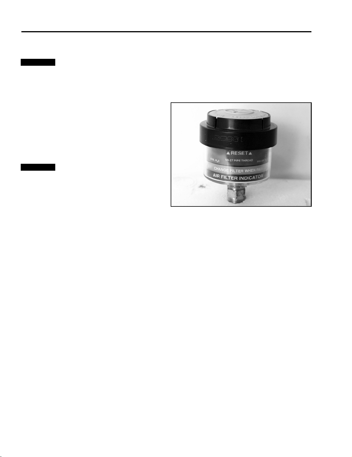
Using the Filter Minder
This machine contains an air cleaner Filter Minder
gauge.
Filter Minder: Check this daily.
The plunger inside the gauge canister will change to
red when the air cleaner element becomes dirty and
restricted. When it changes red, air cleaner
maintenance is required.
2 - 4 Mid-Mount Z Service Manual
MAINTENANCE
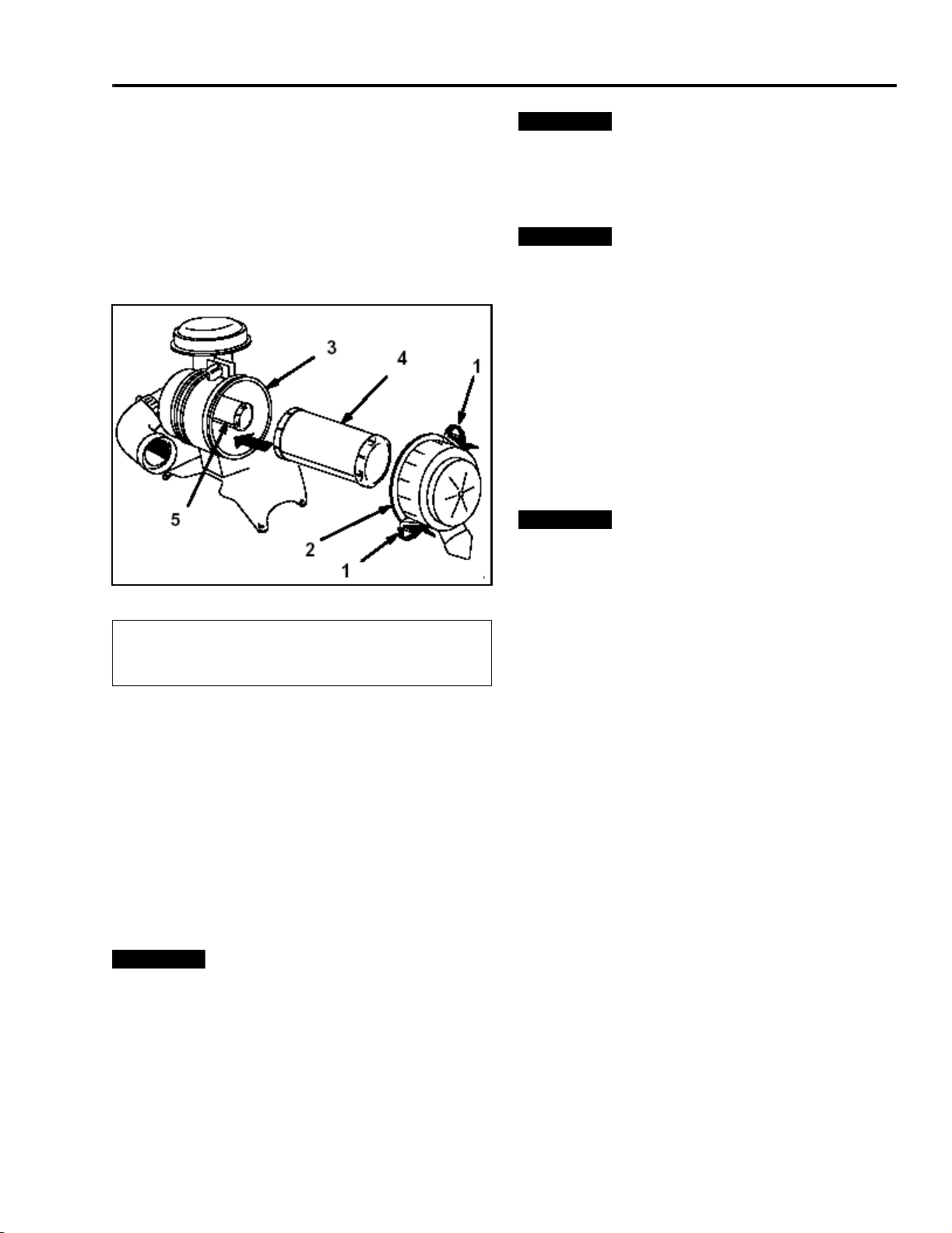
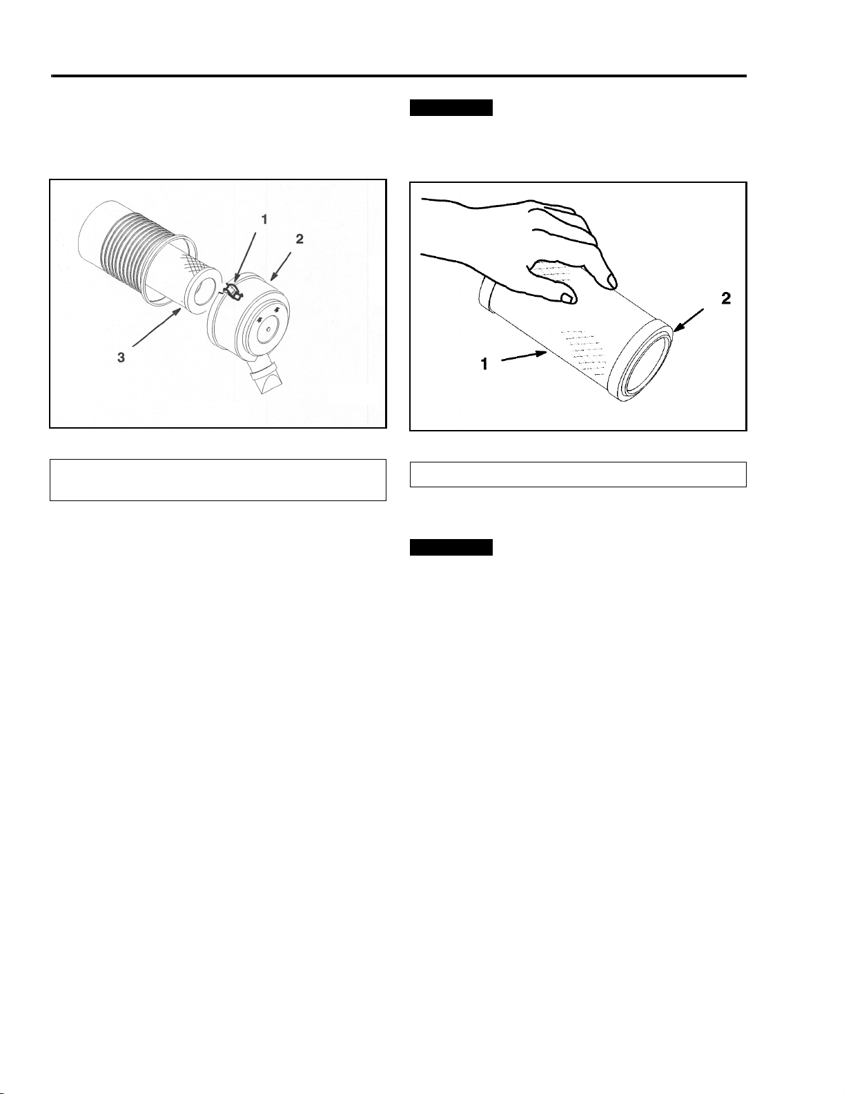
Removing the Air Cleaner
1. Disengage the power take off (PTO), set the
parking brake, and turn the ignition key to off.
Remove the key. Remove spark plug wire(s).
2. Release the latches on the air cleaner and pull the
air cleaner cover off of the air cleaner body (Figure
5).
Important
hose at least 2 inches from the filter. Replace air filters
if they are damaged or cannot be cleaned.
Installing the Filters
Important
operate the engine with both air filters and cover
installed.
1. If installing new filters, check each filter for
shipping damage. Do not use a damaged filter.
2. If the safety filter is being replaced, carefully slide
it into the filter body (Figure 5).
3. Carefully slide the primary filter over the safety
filter (Figure 5). Ensure that it is fully seated by
pushing on the outer rim of the filter while
installing it.
Important
the filter.
Do not exceed 100 psi and keep the
To prevent engine damage, always
Do not press on the soft inside area of
Figure 5
(1) Latches
(2) Air Cleaner Cover
(3) Air Filter Body
3. Clean the inside of the air cleaner cover with
compressed air.
4. Gently slide the primary filter out of the air cleaner
body (Figure 5). Avoid knocking the filter into the
side of the body. Do not remove the safety filter,
unless you intend to replace it as well.
5. Inspect the primary filter for damage by looking
into the filter while shining a bright light on the
outside of the filter. Holes in the filter will appear
as bright spots. If the filter is damaged discard it.
Important
the safety filter is dirty, then the primary filter is
damaged and you should replace both filters.
Never attempt to clean the safety filter. If
(4) Primary Filter
(5) Safety Filter
m-4815
4. Install the air cleaner cover with the side indicated
as UP facing up and secure the latches (Figure 5).
Servicing the Air Cleaner Liquid-Cooled
Models
Paper Element:
• Clean after 50 operating hours.
• Replace after 300 operating hours.
NOTE: Service the air cleaner more frequently (every
few hours) if operating conditions are extremely dusty
or sandy.
Removing the Paper Element
1. Disengage the power take off (PTO), set the
parking brake, stop the engine, and remove the
key.
2. Tilt the seat up and tilt the engine cover forward.
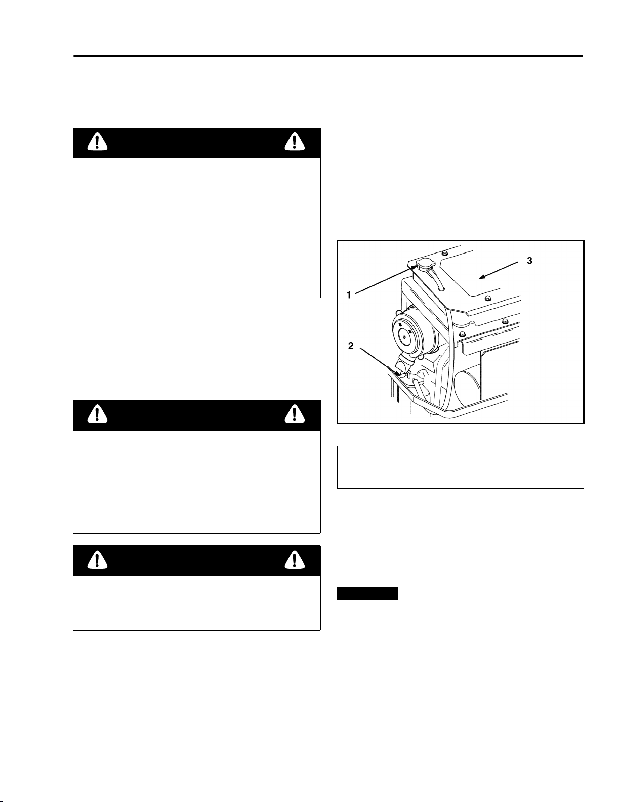
Cleaning the Primary Filter
Blow compressed air from the inside to the outside of
the primary filter.
Mid-Mount Z Service Manual 2 - 5
MAINTENANCE
3. Clean around the air cleaner to prevent dirt from
getting into the engine and causing damage.
Loosen the retaining clips and remove the air
cleaner cover (Figure 6).
(1) Retaining Clip
(2) Air Cleaner Cover
Figure 6
(3) Air Filter
m-4382
Important
pressurized air or liquids, such as solvent, gas, or
kerosene. Replace the paper element if it is damaged,
or cannot be cleaned thoroughly.
(1) Paper Element (2) Rubber Seal
Never clean the paper element with
Figure 7
m-4383
Cleaning the Paper Elements
1. Lightly tap the element on a flat surface to remove
dust and dirt (Figure 7).
2. Inspect the element for tears, an oily film, and
damage to the rubber seal.
Installing the Paper Elements
Important
operate the engine with the paper air cleaner installed.
1. Carefully slide the element into the compartment
(Figure 6).
2. Place the air cleaner cover into the compartment
and latch the retaining clips (Figure 6).
To prevent engine damage, always
Cleaning the Engine Fins
Every 100 hours clean engine cylinder and cylinder
head cooling fins. Also clean around carburetor,
governor levers and linkage. This will make sure
adequate cooling to hydraulic pumps, motors and
engine and will reduce the possibility of overheating
and mechanical damage.
Remove the panels from the engine shroud.
Clean the engine cooling fins.
Install the panels onto the engine shroud.
2 - 6 Mid-Mount Z Service Manual
MAINTENANCE
Servicing the Cooling System
Checking the Radiator Coolant
Danger
Discharge of hot pressurized coolant or touching
hot radiator and surrounding parts can cause
severe burns.
• Do not remove the radiator cap when the
engine is hot. Always allow the engine to cool
at least 15 minutes or until the radiator cap is
cool enough to touch without burning your
hand before removing the radiator cap.
• Do not touch radiator and surrounding parts
that are hot.
Check the cooling system level daily.
Fluid Type: 50/50 mix of permanent antifreeze
(ethylene glycol) and water.
3. With the engine cool, remove the radiator cap
(Figure 8).
4. If the coolant level is low, add a 50/50 mixture of
permanent antifreeze and water until the radiator
is completely full without overflowing.
5. Install the radiator cap. Completely seat the cap
by pushing down and turning it until it stops.
6. Add a 50/50 coolant mix to the overflow bottle and
fill it to the indicator line on the bottle, if required
(Figure 8).
Cooling System Capacity: 128 oz. (3.8 l).
Danger
Rotating shaft and fan can cause personal injury.
• Do not operate the machine without the covers
in place.
• Keep fingers, hands and clothing clear of
rotating fan and drive shaft.
• Shut off the engine and remove the ignition
key before performing maintenance.
Caution
Swallowing engine coolant can cause poisoning.
• Do not swallow engine coolant.
• Keep out of reach from children and pets.
1. Position the machine on a level surface, stop the
engine, and set the parking brake.
2. Tilt the seat up and tilt the engine hood forward.
Figure 8
(1) Radiator Cap
(2) Antifreeze Overflow
Bottle
Cleaning the Cooling System
Clean the cooling system daily before each use.
1. Position the machine on a level surface, stop the
engine, and set the parking brake.
Important
from the pump drive belt compartment. Check more
often in dry conditions.
2. Tilt the seat up and raise the rubber flap above the
drive belt compartment.
3. Remove debris from the drive belt compartment
and hydraulic pumps.
Before starting the engine, clean grass
(3) Radiator Core and
Screen
m-5031-1
Mid-Mount Z Service Manual 2 - 7
MAINTENANCE
4. Remove debris from the screen on the engine
cover.
5. Tilt the engine cover forward.
6. Remove debris from the radiator core and engine
(Figure 8).
Important
7. Inspect the seals on the engine cover and replace
them if needed.
8. Close the engine cover and tilt the seat back.
Changing the Engine Coolant
Change the engine coolant every 400 hours.
Do not damage the radiator cooling fins.
Danger
Discharge of hot pressurized coolant or touching
hot radiator and surrounding parts can cause
severe burns.
3. With the engine cool, drain the coolant by
loosening the drain cock in the right rear corner
(Figure 9).
4. The engine block must be drained by removing
the drain plug from the engine block (Figure 10).
NOTE: The drain plug is black in color and is located
near the oil filter (Figure 10).
5. Install all drain plugs, the radiator hose, and
tighten the drain cock.
• Do not remove the radiator cap when the
engine is hot. Always allow the engine to cool
at least 15 minutes or until the radiator cap is
cool enough to touch without burning your
hand before removing the radiator cap.
• Do not touch radiator and surrounding parts
that are hot.
Danger
Rotating shaft and fan can cause personal injury.
• Do not operate the machine without the covers
in place.
• Keep fingers, hands and clothing clear of
rotating fan and drive shaft.
• Shut off the engine and remove the ignition
key before performing maintenance.
1. Position the machine on a level surface, stop the
engine, and set the parking brake.
2. Tilt the seat up and tilt the engine hood forward.
Figure 9
(1) Drain Cock (right rear of radiator)
Figure 10 m-5030
(1) Coolant Drain Plug (black in color)
m-4379
2 - 8 Mid-Mount Z Service Manual
MAINTENANCE
6. Drain the coolant from the overflow bottle.
7. Remove the radiator cap and add a 50/50 mixture
of permanent antifreeze and water until the
radiator is completely full.
8. Wait 2 minutes and check if the coolant stays up
to the full level. Add a 50/50 mixture of permanent
antifreeze and water until the radiator is
completely full, if required. Repeat until the
coolant stays up to the full level.
9. With the radiator cap off, tilt the engine cover
down and put the seat down. Start the engine.
Run the engine until it is warm.
10. Tilt the seat up, tilt the engine hood forward, and
keep the engine running. As air is purged from the
engine block and the coolant level drops, add
additional coolant to the radiator it is until full.
11. Install the radiator cap. Completely seat the cap
by pushing down and turning it until it stops.
12. Shut off the engine.
13. Check for any leaks in the cooling system.
14. Close the engine cover and tilt the seat back.
Important
hours of changing the coolant.
Check the coolant level after the first 8
Inspecting the Cooling System
Inspect the radiator and the hoses initially and after the
first 8 operating hours.
Inspect the radiator and the hoses every 200 hours.
Check the hoses and radiator for cracks, dents, and
fractured seams. Repair or replace damaged hoses or
the radiator.
Servicing the Fuel Filter
Replace the fuel filter after every 200 operating hours
or yearly, whichever occurs first.
Replacing the Fuel Filter
Never install a dirty filter if it is removed from the fuel
line.
1. Disengage the power take off (PTO) and turn the
ignition key to off. Move levers to neutral locked
position and apply parking brake. Remove the
key.
2. Close fuel shut-off valve on console.
3. Squeeze the ends of the hose clamps together
and slide them away from the filter (Figure 12).
Figure 12
Figure 11
(1) Radiator Cap (2) Antifreeze Overflow Bottle
Mid-Mount Z Service Manual 2 - 9
m-5031-2
(1) Filter (2) Hose Clamp
4. Remove the filter from the fuel lines.
m-3217
MAINTENANCE
5. Install a new filter and move the hose clamps
close to the filter (Figure 12).
6. Wipe up any spilled fuel.
Open fuel shut-off valve on console.
Servicing the Spark Plug
Check the spark plug(s) after every 200 operating
hours. Make sure the air gap between the center and
side electrodes is correct before installing the spark
plug. Use a spark plug wrench for removing and
installing the spark plug(s) and a gapping tool/feeler
gauge to check and adjust the air gap. Install a new
spark plug(s) if necessary.
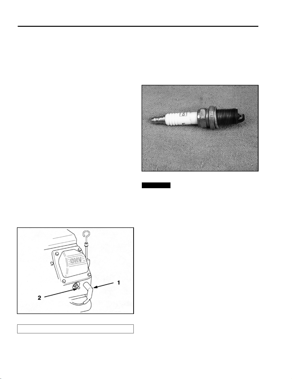
Type: Champion RC12YC (or equivalent).
Air Gap: 0.030 in. (0.76mm).
Removing the Spark Plug
1. Disengage the power take off (PTO) and turn the
ignition key to off. Move levers to neutral locked
position and apply parking brake. Remove the
key.
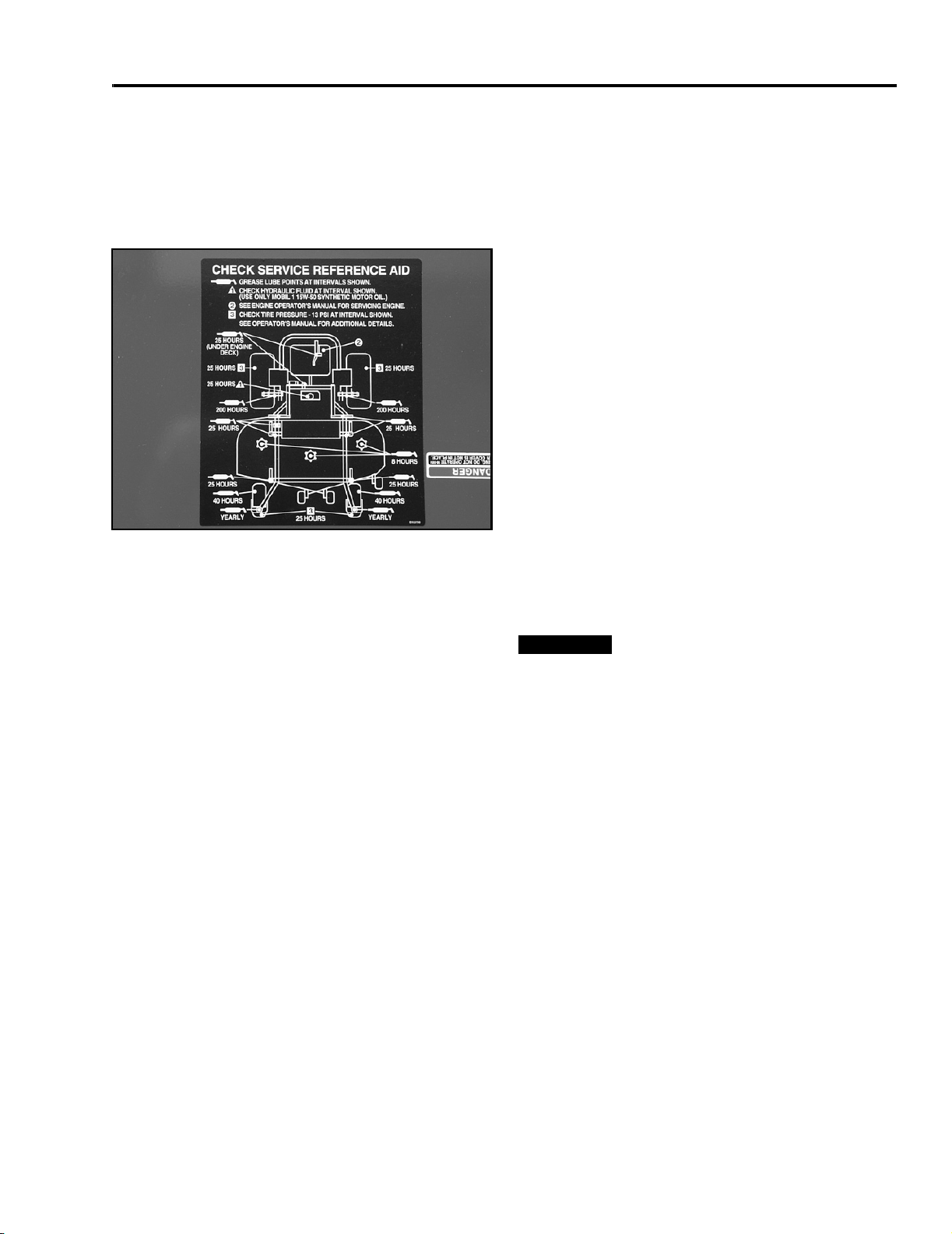
2. Pull the wire(s) off the spark plug(s) (Figure 13).
Now clean around the spark plug(s) to prevent dirt
from falling into the engine and potentially causing
damage.
(s)
3. Remove the spark plug(s) and metal washer.
Checking the Spark Plug
1. Look at the center of the spark plug(s) (Figure 14).
If you see light brown or gray on the insulator, the
engine is operating properly. A black coating on
the insulator usually means the air cleaner is dirty.
Figure 14
Important
replace the spark plug(s) when it has: a black coating,
worn electrodes, an oily film, or cracks.
2. Check the gap between the center and side
electrodes (Figure 14). Bend the side electrode
(Figure 14) if the gap is not correct.
Never clean the spark plug(s). Always
1101-020
Installing the Spark Plug
1. Install the spark plug(s). Make sure the air gap is
set correctly.
2. Tighten the spark plug(s) to 20 ft-lb (27 N·m).
3. Push the wire(s) onto the spark plug(s) (Figure
13).
(s)
Check Valve Clearance
Refer to the engine manufacturer’s service manual for
service interval and instructions.
Figure 13
(1) Spark Plug Wire (2) Spark Plug
2 - 10 Mid-Mount Z Service Manual
m-3218
MAINTENANCE
Greasing and Lubrication
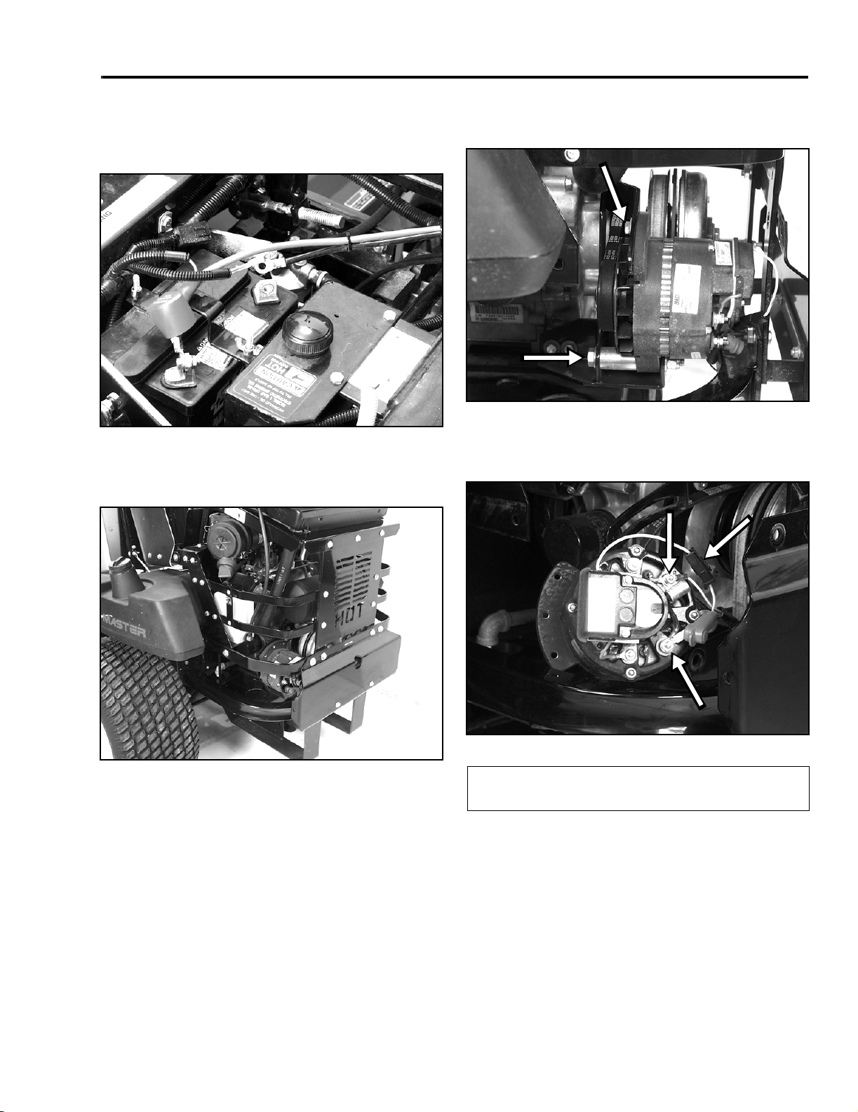
Lubricate the machine when shown on the Check
Service Reference Aid decal (Figure 15). Grease
more frequently when operating conditions are
extremely dusty or sandy.
Figure 15
Grease Type: General-purpose grease.
How to Grease
1101-017
3. Remove grease zerk in hole. Reinstall hex plug
and cap.
Where to Add Grease
Lubricate the grease fittings as shown on the Check
Service Reference Aid decal (Figure 15).
Where to Add Light Oil or Spray Lubrication
Lubricate the machine in the following areas with spray
type lubricant or light oil. Lubricate every 160 hours.
• Seat switch actuator.
• Brake handle pivot.
• Brake rod bushings.
• Motion control bronze bushings.
Greasing the Bearings
The cutting unit must be lubricated daily. Refer to the
“Recommended Maintenance Schedule” on page 2 - 1.
Grease with No. 2 general purpose lithium base or
molybdenum base grease.
1. Disengage the power take off (PTO) and turn the
ignition key to off. Move levers to neutral locked
position and apply parking brake. Remove the
key.
2. Clean the grease fittings with a rag. Make sure to
scrape any paint off the front of the fitting(s).
3. Connect a grease gun to the fitting. Pump grease
into the fittings until grease begins to ooze out of
the bearings.
4. Wipe up any excess grease.
Greasing the Front Castor Pivots
Lubricate the front castor pivots once a year.
1. Remove hex plug and cap. Thread a grease zerk
into hole.
2. Pump grease into zerk until it oozes out around
top bearing.
Important
grease daily.
1. Stop the engine, set the parking brake, remove
the key and disconnect the spark plug wire(s) from
the spark plug(s).
2. Grease the fittings on the three spindle bearings
until grease comes out lower seals (Figure 15).
3. Grease the fittings on the push arms (Figure 15).
Make sure cutting unit spindles are full of
Mid-Mount Z Service Manual 2 - 11

THIS PAGE INTENTIONALLY LEFT BLANK
2 - 12 Mid-Mount Z Service Manual
ENGINE
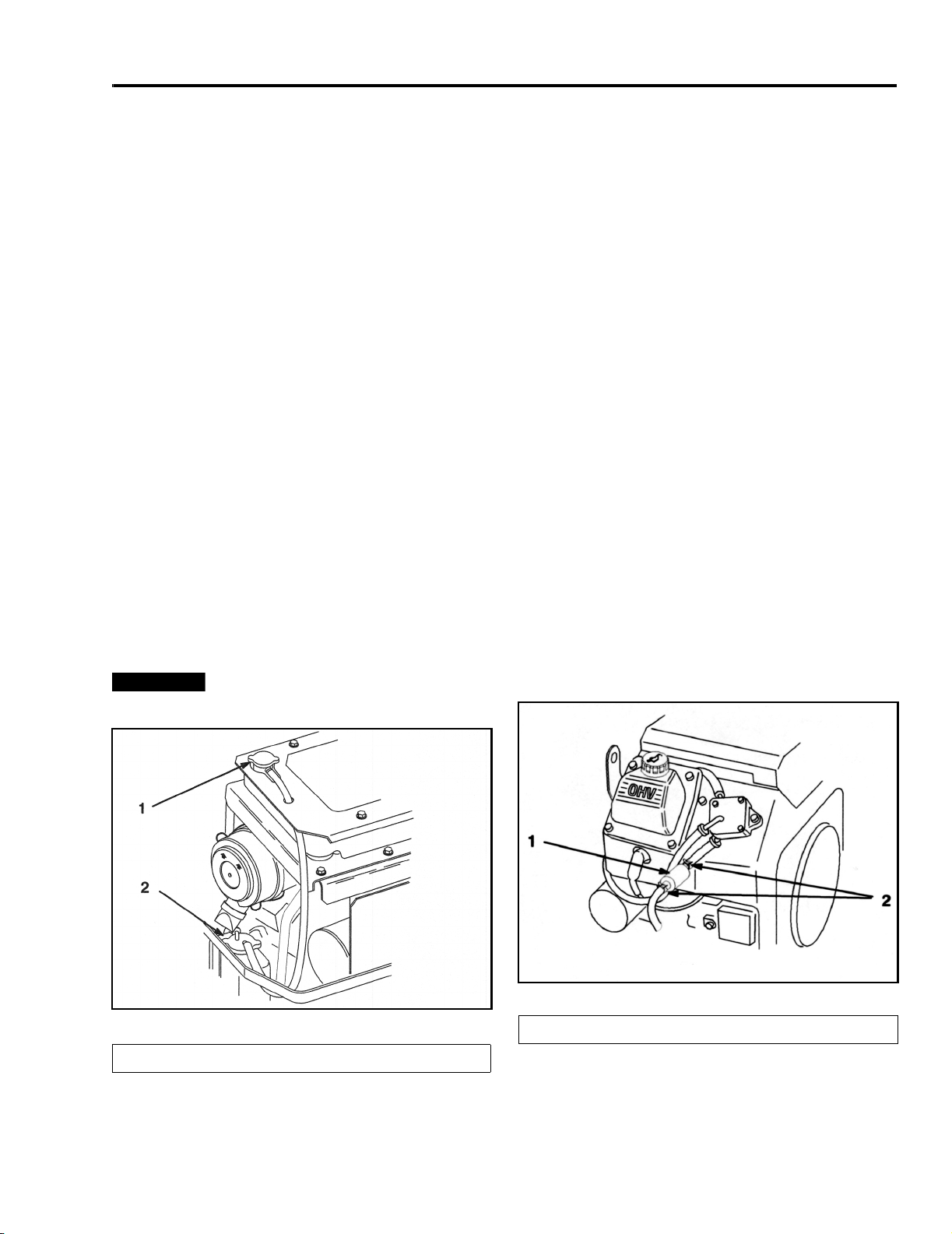
External Alternator Remove & Replace
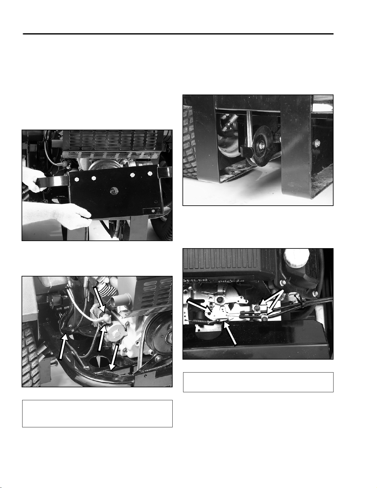
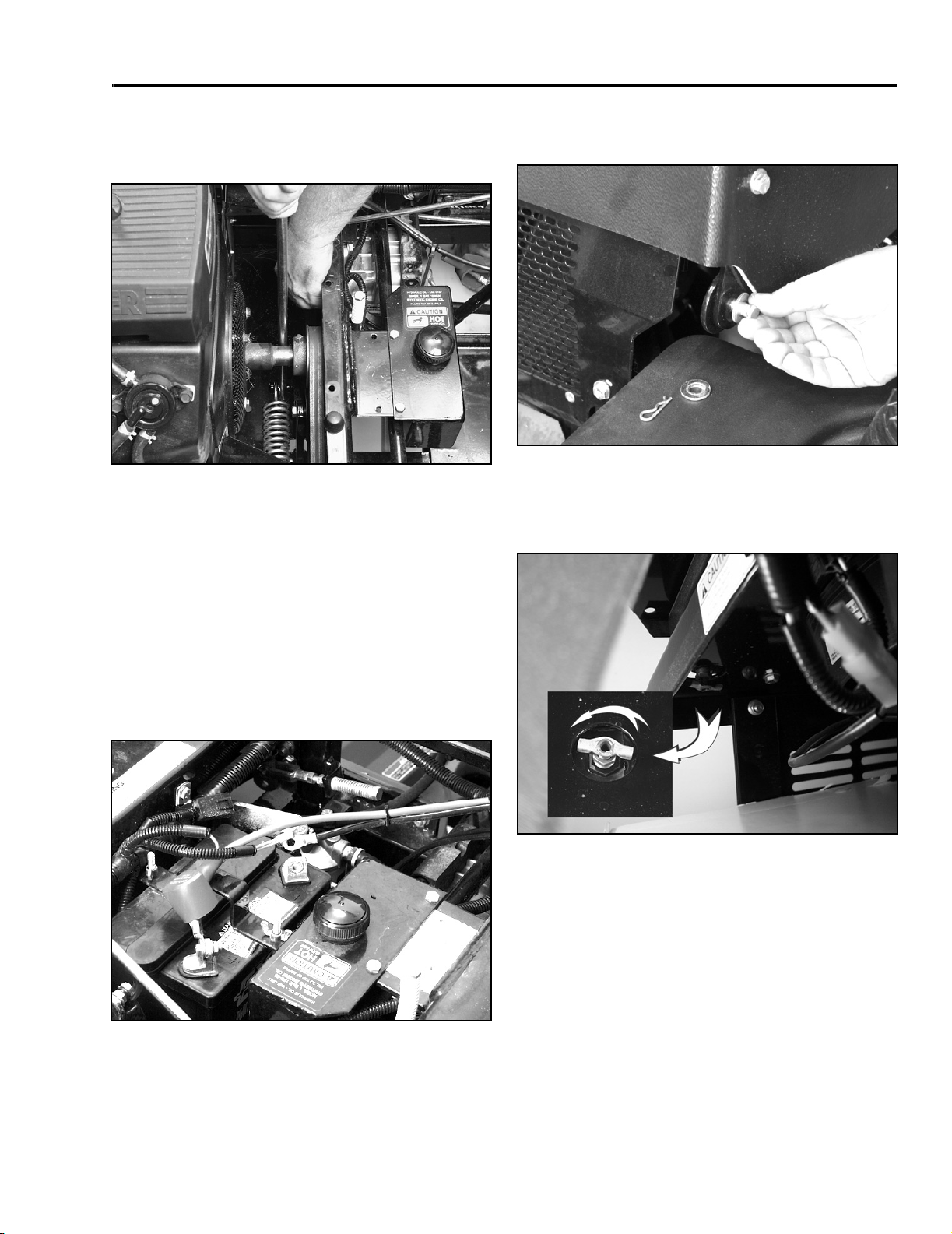
1. Disconnect the battery negative cable.
Figure 16
2. Remove the lower engine protection bracket and
set the coolant recovery bottle off to the side.
0507-001
3. Remove the alternator adjustment bolt and pivot
bolt.
Figure 18
4. Remove the alternator belt and rotate the
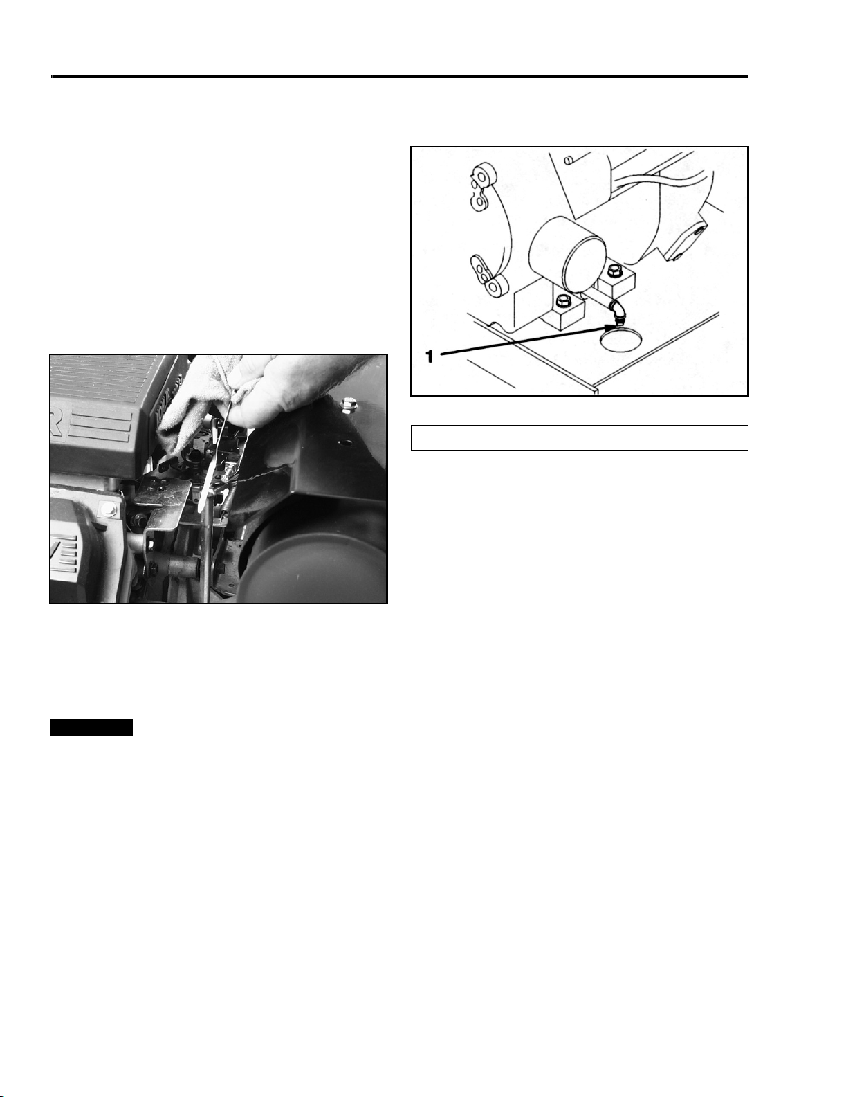
alternator to gain access to the wiring.
A
0508-003
B
C
Figure 19
Figure 17
Mid-Mount Z Service Manual 3 - 1
0508-002
(A) Ground Wire
(B) Exciter Wire
5. Remove the alternator output wire, ground wire,
and exciter wire.
6. Inspect the alternator belt for wear, cracking, or
other damage.
7. Reverse procedure to reinstall.
(C) Output Wire
0508-004
ENGINE
Engine Remove & Replace
Air-Cooled
1. Disconnect the negative battery cable.
2. Remove the PTO clutch anchor bolt from the
clutch guard.
3. Remove the clutch guard and clutch guard
brackets (Figure 20).
Figure 20
1023-011
5. Disconnect the PTO clutch electrical plug and
main wiring harness connector (Figure 21).
6. Release the tension from the drive belt by raising
the lever against the spring tension and remove
the belt from the PTO pulley (Figure 22).
Figure 22
7. Remove the clamps securing the choke and
throttle cables. Then remove the Z bends from
the choke and throttle levers (Figure 23).
1101-011
4. Remove the battery cable, main power feed, and
solenoid wire from the starter solenoid (Figure 21).
A
C
D
(A) Battery Cable/
Power Feed
(B) Solenoid Wire
B
Figure 21
(C) Clutch Plug
(D) Main Harness
Connector
1023-008
A
C
B
Figure 23
(A) Cable Clamps
(B) Throttle Lever
8. Place the fuel tank selector lever in the off position
and disconnect the fuel supply line from the fuel
filter.
(C) Choke Lever
1023-005
3 - 2 Mid-Mount Z Service Manual
ENGINE
9. Using a suitable pry bar, release the idler pulley
spring tension and remove the hydraulic pump
drive belt.
Figure 24
10. Remove the 4 engine mounting bolts.
11. Slide the engine toward the rear of the machine
and rotate it slightly counterclockwise until the
hydraulic pump belt drive pulley clears the
chassis. Then, lift the engine from the chassis.
1023-012
2. Remove the pins from the radiator cover and lift
off the cover.
Figure 26
3. Remove the radiator cap and open the drain
petcock to drain the coolant into a suitable
container.
0507-002
Engine Remove & Replace
Liquid-Cooled
1. Disconnect the negative battery cable.
Figure 25
0507-001
Figure 27
0507-003
Mid-Mount Z Service Manual 3 - 3
 Loading...