

Page 1
FormNo.3380-752RevA
ZMaster
®
Commercial2000
SeriesRidingMower
with48in,52in,or60inTURBOFORCE
DischargeMower
ModelNo.74141—SerialNo.314000001andUp
ModelNo.74143—SerialNo.314000001andUp
ModelNo.74145—SerialNo.314000001andUp
®
Side
Registeratwww.T oro.com.
OriginalInstructions(EN)
*3380-752*A
Page 2

WARNING
g017416
1
Introduction
CALIFORNIA
Proposition65Warning
Thisproductcontainsachemicalorchemicals
knowntotheStateofCaliforniatocausecancer,
birthdefects,orotherreproductiveharm.
Theengineexhaustfromthisproduct
containschemicalsknowntotheStateof
Californiatocausecancer,birthdefects,
orotherreproductiveharm.
ThissparkignitionsystemcomplieswithCanadianICES-002
Becauseinsomeareastherearelocal,state,orfederal
regulationsrequiringthatasparkarresterbeusedonthe
engineofthismachine,asparkarresterisavailableas
anoption.Ifyourequireasparkarrestor,contactyour
AuthorizedToroDealer.
GenuineTorosparkarrestersareapprovedbytheUSDA
ForestryService.
Note:ItisaviolationofCaliforniaPublicResource
CodeSection4442touseoroperatetheengineonany
forest-covered,brush-covered,orgrass-coveredlandwithout
asparkarrestermufermaintainedinworkingorder,or
theengineconstricted,equipped,andmaintainedforthe
preventionofre.Otherstatesorfederalareasmayhave
similarlaws.
Thisrotary-blade,ridinglawnmowerisintendedtobeused
byresidentialhomeownersorprofessional,hiredoperators.
Itisdesignedprimarilyforcuttinggrassonwell-maintained
lawnsonresidentialorcommercialproperties.Itisnot
designedforcuttingbrushorforagriculturaluses.
Readthisinformationcarefullytolearnhowtooperateand
maintainyourproductproperlyandtoavoidinjuryand
productdamage.Youareresponsibleforoperatingthe
productproperlyandsafely .
YoumaycontactTorodirectlyatwww .Toro.comforproduct
andaccessoryinformation,helpndingadealer,ortoregister
yourproduct.
Wheneveryouneedservice,genuineToroparts,oradditional
information,contactanAuthorizedServiceDealerorToro
CustomerServiceandhavethemodelandserialnumbersof
yourproductready .Figure1identiesthelocationofthe
modelandserialnumbersontheproduct.Writethenumbers
inthespaceprovided.
WARNING
Removingstandardoriginalequipmentpartsand
accessoriesmayalterthewarranty,traction,and
safetyofthemachine.FailuretouseoriginalToro
partscouldcauseseriousinjuryordeath.Making
unauthorizedchangestotheengine,fuelorventing
system,mayviolateEPAandCARBregulations.
Replaceallpartsincluding,butnotlimitedto,tires,
belts,blades,andfuelsystemcomponentswith
originalT oroparts.
Theenclosed
informationregardingtheUSEnvironmentalProtection
Agency(EPA)andtheCaliforniaEmissionControl
Regulationofemissionsystems,maintenance,and
warranty.Replacementsmaybeorderedthroughthe
enginemanufacturer.
Engine Owner's Man ual
issuppliedfor
Figure1
1.Modelandserialnumberlocation
ModelNo.
SerialNo.
Thismanualidentiespotentialhazardsandhassafety
messagesidentiedbythesafetyalertsymbol(Figure2),
whichsignalsahazardthatmaycauseseriousinjuryordeath
ifyoudonotfollowtherecommendedprecautions.
©2013—TheToro®Company
8111LyndaleAvenueSouth
Bloomington,MN55420
Contactusatwww.T oro.com.
2
PrintedintheUSA.
AllRightsReserved
Page 3

Figure2
1.Safetyalertsymbol
Thismanualuses2wordstohighlightinformation.
Importantcallsattentiontospecialmechanicalinformation
andNoteemphasizesgeneralinformationworthyofspecial
attention.
Contents
Introduction..................................................................2
Safety...........................................................................4
SafeOperatingPractices...........................................4
ToroMowerSafety..................................................5
SlopeIndicator.......................................................7
SafetyandInstructionalDecals.................................8
ProductOverview.........................................................12
Controls...............................................................12
Specications........................................................13
Operation....................................................................14
AddingFuel...........................................................14
CheckingtheEngine-oilLevel..................................15
BreakingInaNewMachine.....................................15
UsingtheRollover-ProtectionSystem(ROPS)............15
ThinkSafetyFirst...................................................16
OperatingtheParkingBrake....................................17
OperatingtheMowerBlade-controlSwitch
(PTO)...............................................................17
OperatingtheThrottle............................................18
OperatingtheChoke...............................................18
OperatingtheIgnitionSwitch..................................18
UsingtheFuelShut-offValve...................................19
StartingandStoppingtheEngine..............................19
UsingtheSafety-interlockSystem.............................20
DrivingForwardorBackward..................................21
StoppingtheMachine.............................................22
AdjustingtheHeight-of-Cut....................................22
AdjustingtheAnti-scalpRollers................................23
PositioningtheSeat................................................23
UsingtheDrive-wheel-releaseValves........................24
UsingtheSideDischarge.........................................24
LoadingMachines..................................................24
TransportingMachines............................................25
OperatingTips......................................................26
Maintenance.................................................................27
RecommendedMaintenanceSchedule(s)......................27
Lubrication...............................................................28
GreasingandLubrication........................................28
GreasingtheMower...............................................28
LubricatingtheCaster-wheelHubs...........................29
EngineMaintenance..................................................30
ServicingtheAirCleaner.........................................30
ServicingtheEngineOil..........................................31
ServicingtheSparkPlug..........................................33
CheckingtheSparkArrester(ifequipped)..................34
FuelSystemMaintenance...........................................35
ReplacingtheFuelFilter..........................................35
ServicingtheFuelTank...........................................35
ElectricalSystemMaintenance....................................36
ServicingtheBattery...............................................36
ServicingtheFuses.................................................37
DriveSystemMaintenance.........................................38
CheckingtheSeatBelt.............................................38
CheckingtheRollover-Protection-System(ROPS)
Knobs...............................................................38
AdjustingtheTracking............................................38
CheckingtheTirePressure......................................39
CheckingtheWheelLugNuts..................................39
AdjustingtheCaster-pivotBearing............................39
AdjustingtheElectricClutch....................................40
CoolingSystemMaintenance......................................40
CleaningtheEngineScreen......................................40
CleaningtheEngineCoolingFinsand
Shrouds.............................................................40
BeltMaintenance......................................................41
InspectingtheBelts................................................41
ReplacingtheMowerBelt........................................41
ReplacingtheHydraulicPump-driveBelt...................42
ControlsSystemMaintenance.....................................43
AdjustingtheControl-handlePosition.......................43
AdjustingtheMotion-controlLinkage.......................43
AdjustingtheMotion-controlDamper......................45
AdjustingtheMotionControlNeutral-lock
Pivot.................................................................45
HydraulicSystemMaintenance....................................46
ServicingtheHydraulicSystem.................................46
ChangingtheHydraulic-systemFilterand
Oil....................................................................46
MowerDeckMaintenance...........................................48
LevelingtheMowerDeck........................................48
ServicingtheCuttingBlades.....................................50
RemovingtheMowerDeck.....................................52
ReplacingtheGrassDeector..................................53
Cleaning...................................................................54
CleaningUndertheMower......................................54
DisposingofWaste.................................................54
Storage........................................................................54
CleaningandStorage..............................................54
Troubleshooting...........................................................56
Schematics...................................................................58
3
Page 4

Safety
Improperuseormaintenancebytheoperatororowner
canresultininjury.Toreducethepotentialforinjury,
complywiththesesafetyinstructions,andpayattentionto
thesafetyalertsymbol,whichmeansCaution,Warning,or
Danger—“personalsafetyinstruction.”Failuretocomply
withtheinstructionsmayresultinpersonalinjuryor
death.
Important:Thismachinewasmanufacturedaccording
totheappropriateregulatorystandardsineffectatthe
timeofmanufacture.Modifyingthismachineinany
waymaycauseittobeoutofcompliancewiththose
standardsandwiththeinstructionsinthisOperator’s
Manual.Modicationstothismachineshouldonlybe
madebyeitherthemanufactureroranAuthorizedT oro
Dealer.
Thisproductiscapableofamputatinghandsandfeet.Follow
allsafetyinstructionstoavoidseriousinjuryordeath.
Theowner/usercanpreventandisresponsibleforaccidents
orinjuriesoccurringtopeople,ordamagetoproperty.
Important:Theadditionofattachmentsmadeby
othermanufacturersthatdonotmeetAmerican
NationalStandardsInstitutecerticationwillcause
noncomplianceofthismachine.
SafeOperatingPractices
ThefollowinginstructionsareadaptedfromANSIstandard
B71.4-2012.
Training
•ReadtheOperator'sManualandothertrainingmaterial.
Note:Iftheoperator(s)ormechanic(s)cannotreadthe
manuallanguage,itistheowner'sresponsibilitytoexplain
thismaterialtothem.
•Becomefamiliarwiththesafeoperationoftheequipment,
operatorcontrols,andsafetysigns.
•Alloperatorsandmechanicsshouldbetrained.The
ownerisresponsiblefortrainingtheusers.
•Neverletchildrenoruntrainedpeopleoperateorservice
theequipment.Localregulationsmayrestricttheageof
theoperator.
•Theowner/usercanpreventandisresponsiblefor
accidentsorinjuriesoccurringtopeople,ordamageto
property.
Preparation
•Evaluatetheterraintodeterminewhataccessoriesand
attachmentsareneededtoproperlyandsafelyperform
thejob.
Note:Onlyuseaccessoriesandattachmentsapproved
bythemanufacturer.
•Wearappropriateclothingincluding:ahardhat,safety
glasses,andhearingprotection.Longhair,looseclothing
orjewelrymaygettangledinmovingparts.
•Inspecttheareawheretheequipmentisused,andremove
allobjectsthatcanbethrownbythemachine.
•Checkthatoperator'spresencecontrols,safetyswitches
andshieldsareattachedandfunctioningproperly.Donot
operateunlesstheyarefunctioningproperly.
Operation
•Lightningcancausesevereinjuryordeath.Iflightning
isseen,orthunderisheardinthearea,donotoperate
themachine;seekshelter.
•Donotrunanengineinanenclosedarea.
•Onlyoperateinwell-litareas,keepingawayfromholes
andhiddenhazards.
•Ensurethatalldrivesareinneutralandthattheparking
brakeisengagedbeforestartingengine.Onlystartthe
enginefromtheoperator’sposition.
•Makesurethatyouhavegoodfootingwhileusingthis
machine,especiallywhenbackingup.
Note:Reducedfootingcouldcauseslipping.
•Slowdownanduseextracareonhillsides.Besureto
travelsidetosideonhillsides.Turfconditionscanaffect
thestabilityofthemachine.Usecautionwhileoperating
neardrop-offs.
•Slowdownandusecautionwhenmakingturnsandwhen
changingdirectionsonslopes.
•Donotraisethemowerdeckwiththebladesrunning.
•DonotoperatethemachinewithoutthePTOshieldor
otherguardssecurelyinplace.Besureallinterlocksare
attached,adjustedproperly,andfunctioningproperly .
•Donotoperatewiththedischargedeectorraised,
removedoraltered,unlessusingagrasscatcher.
•Donotchangetheenginegovernorsettingoroverspeed
theengine.
•Stoponlevelground,disengagedrives,engagethe
parkingbrake(ifprovided),shutofftheenginebefore
leavingtheoperator'spositionforanyreason,including
emptyingthecatchersoruncloggingthechute.
•Stopequipmentandinspectthebladesafterstriking
objectsorifanabnormalvibrationoccurs.Makethe
necessaryrepairsbeforeresumingoperations.
•Keepyourhandsandfeetawayfromthecuttingunit.
•Lookbehindanddownbeforebackinguptoensurea
clearpath.
4
Page 5

•Keeppetsandbystandersawayfromanoperating
machine.
•Slowdownandusecautionwhenmakingturnsand
crossingroadsandsidewalks.Stopthebladesifyouare
notmowing.
MaintenanceandStorage
•Disengagedrives,settheparkingbrake,stoptheengine,
andremovethekeyordisconnectspark-plugwire.Wait
forallmovementtostopbeforeadjusting,cleaning,or
repairing.
•Beawareofthemower-dischargedirectionanddonot
pointitatanyone.
•Donotoperatethemowerundertheinuenceofalcohol
ordrugs.
•Usecarewhenloadingorunloadingthemachineinto
orfromatrailerortruck.
•Usecarewhenapproachingblindcorners,shrubs,trees,
orotherobjectsthatmayobscurevision.
Safehandlingoffuels
•Toavoidpersonalinjuryorpropertydamage,use
extremecareinhandlinggasoline.Gasolineisextremely
ammableandthevaporsareexplosive.
•Extinguishallcigarettes,cigars,pipes,andothersources
ofignition.
•Useonlyanapprovedfuelcontainer.
•Donotremovethefuelcaporaddfuelwiththeengine
running.
•Allowtheenginetocoolbeforefueling.
•Donotrefuelthemachineindoors.
•Donotstorethemachineorfuelcontainerwherethere
isanopename,spark,orpilotlightsuchasonawater
heateroronotherappliances.
•Donotllcontainersinsideavehicle,onatruck,orona
trailerbedwithaplasticliner.Alwaysplacecontainerson
thegroundawayfromyourvehiclebeforelling.
•Removeequipmentfromthetruckortrailerandfuelit
ontheground.Ifthisisnotpossible,thenaddfuelwith
suchequipmentasaportablecontainer,ratherthanfrom
afueldispensernozzle.
•Keepthenozzleincontactwiththerimofthefueltank
orcontaineropeningatalltimesuntilfuelingiscomplete.
•Parkthemachineonalevelsurface.
•Cleangrassanddebrisfromthecuttingunit,drives,
mufers,andenginetohelppreventres.
•Cleanupoilorfuelspillage.
•Lettheenginecoolbeforestoring.
•Donotstorefuelnearamesordrainindoors.
•Donotallowuntrainedpersonneltoservicemachine.
•Usejackstandstosupportcomponentswhenrequired.
•Carefullyreleasepressurefromcomponentswithstored
energy.
•Disconnectthebatteryorremovethespark-plugwire
beforemakinganyrepairs.Disconnectthenegative
terminalrstandthepositiveterminallast.Reconnect
thepositiverstandnegativelast.
•Usecarewhencheckingtheblades.Wraptheblade(s)or
weargloves,andusecautionwhenservicingthem.Only
replaceblades;donotstraightenorweldthem.
•Keephandsandfeetawayfrommovingparts.Ifpossible,
donotmakeadjustmentswiththeenginerunning.
•Keepallpartsingoodworkingconditionandallhardware
tightened.Replaceallwornordamageddecals.
Hauling
•Usecarewhenloadingorunloadingthemachineintoa
traileroratruck.
•Usefull-widthrampsforloadingmachineintoatrailer
oratruck.
•Tiethemachinedownsecurelyusingstraps,chains,cable,
orropes.Bothfrontandrearstrapsshouldbedirected
downandoutwardfromthemachine.
•Donotuseanozzlelockopendevice.
•Iffuelisspilledonclothing,changeyourclothing
immediately.
•Donotoverllfueltank.Replacefuelcapandtighten
securely.
ToroMowerSafety
ThefollowinglistcontainssafetyinformationspecictoToro
productsandothersafetyinformationyoumustknow.
Thisproductiscapableofamputatinghandsandfeet,and
throwingobjects.Alwaysfollowallsafetyinstructionsto
avoidseriousinjuryordeath.
Thisproductisdesignedforcuttingandrecyclinggrass,or,
whenequippedwithagrassbagger,forcatchingcutgrass.
Anyuseforpurposesotherthanthesecouldprovedangerous
totheuserandbystanders.
5
Page 6

GeneralOperation
•Besurethattheareaisclearofbystandersbeforemowing.
Stopthemachineifanyoneentersthearea.
•Donottouchequipmentorattachmentpartswhichmay
behotfromoperation.Allowallofthepartstocool
beforeattemptingtomaintain,adjust,orservicethe
machine.
•UseonlyToro-approvedattachments.Warrantymaybe
voidedifusedwithanyunapprovedattachments.
•Checkcarefullyforoverheadclearances(i.e.branches,
doorways,electricalwires,etc.)beforeoperatingunder
anyobjects,anddonotcontactthem.
•Slowdownbeforemakingturnsanduseextracaution.
•Usecautionwhenridingtheplatformovercurbs,rocks,
roots,orotherobstructions.
•Lookbehindanddownbeforebackinguptoensurea
clearpath.Useextracarewhenoperatinginreverse.
•Donotjerkthecontrols;useasteadymotion.
•Whenloadingorunloadingthemachine,useone
full-widthrampthatiswideenoughtoextendbeyond
thewidthofthemachine.
•Donotcarrypassengers.
•Donotcarryequipmentonthemachine.
UsingtheRolloverProtectionSystem
(ROPS)
•TheROPSisanintegralandeffectivesafetydevice.Keep
theROPSintheraisedandlockedpositionandusethe
seatbeltwhenoperatingthemachine.
•LowertheROPStemporarilyonlywhenabsolutely
necessary.DonotweartheseatbeltwhentheROPSis
foldeddown.
•BeawarethereisnorolloverprotectionwhentheROPS
isinthedownposition.
•Becertainthattheseatbeltcanbereleasedquicklyin
theeventofanemergency.
•Checktheareatobemowedandneverfolddownthe
ROPSinareaswherethereareslopes,dropoffsorwater.
•Checkcarefullyforoverheadclearances(i.e.branches,
doorways,electricalwires)beforedrivingunderany
objectsanddonotcontactthem.
•KeeptheROPSinsafeoperatingconditionby
periodicallythoroughlyinspectingfordamageand
keepingallmountingfastenerstight.
•ReplaceadamagedROPS.Donotrepairorrevise.
•DonotremovetheROPS.
•AnyalterationstoaROPSmustbeapprovedbythe
manufacturer.
SlopeOperation
Allslopesandrampsrequireextracaution.Ifyoufeeluneasy
onaslope,donotmowit.
•Removeobstaclessuchasrocks,treelimbs,etc.fromthe
mowingarea.
•Watchforholes,rutsorbumps.
Note:Tallgrasscanhideobstacles.
•Usecautionneardrop-offs,ditches,orembankments.
Note:Themachinecouldsuddenlyturnoverifawheel
goesovertheedgeofaclifforditch,orifanedgecavesin.
•Useextracarewithgrasscatchersorotherattachments.
Note:Thesecanchangethestabilityofthemachine.
•Keepallmovementonslopesslowandgradual.
•Donotmakesuddenchangesinspeedordirection.
•Mowslopessidetoside.
•Donotmowslopesgreaterthan20degrees.
Service
•Donotstorethemachineorafuelcontainerinsidewhere
thereisanopename,suchasnearawaterheateror
furnace.
•Keepthenutsandboltstight,especiallythe
blade-attachmentbolts.
•Neverinterferewiththeintendedfunctionofasafety
deviceorreducetheprotectionprovidedbyasafety
device.Checktheirproperoperationregularly.
•Tobestprotectyourinvestmentandmaintainoptimal
performanceofyourToroequipment,countonToro
genuineparts.Whenitcomestoreliability,T orodelivers
replacementpartsdesignedtotheexactengineering
specicationsofourequipment.Forpeaceofmind,insist
onTorogenuineparts.
•Checkbrakeoperationfrequently .Adjustandserviceas
required.
6
Page 7
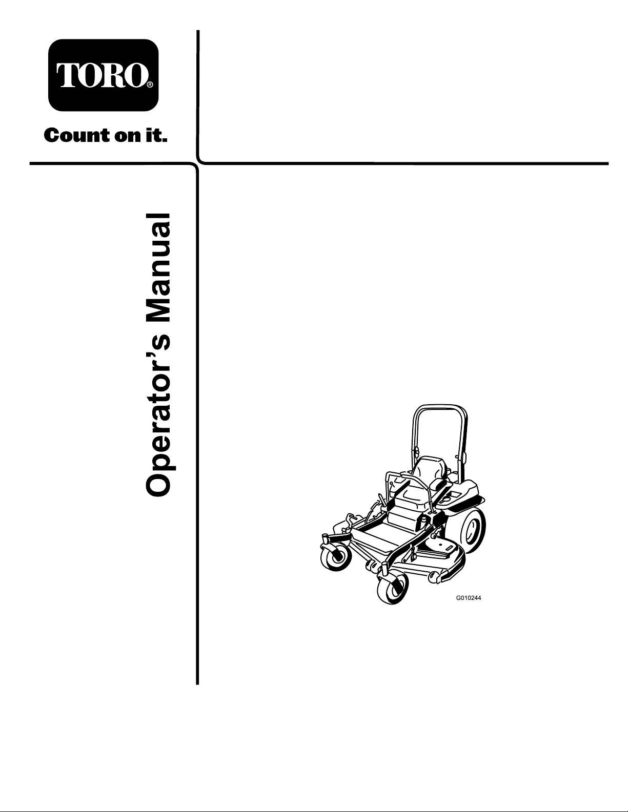
SlopeIndicator
G011841
Figure3
Thispagemaybecopiedforpersonaluse.
1.Themaximumslopeyoucansafelyoperatethemachineonis15degrees.Usetheslopecharttodeterminethedegreeofslope
ofhillsbeforeoperating.Donotoperatethismachineonaslopegreaterthan15degrees.Foldalongtheappropriateline
tomatchtherecommendedslope.
2.Alignthisedgewithaverticalsurface,atree,building,fencepole,etc.
3.Exampleofhowtocompareslopewithfoldededge.
7
Page 8

SafetyandInstructional
Decals
Safetydecalsandinstructionsareeasilyvisibletotheoperatorandarelocatednearanyareaofpotential
danger.Replaceanydecalthatisdamagedorlost.
68-8340
1-403005
98-5954
103-2076
54-9220
Manufacturer'sMark
1.Indicatesthebladeisidentiedasapartfromtheoriginal
machinemanufacturer.
58-6520
1.Grease
66-1340
8
Page 9
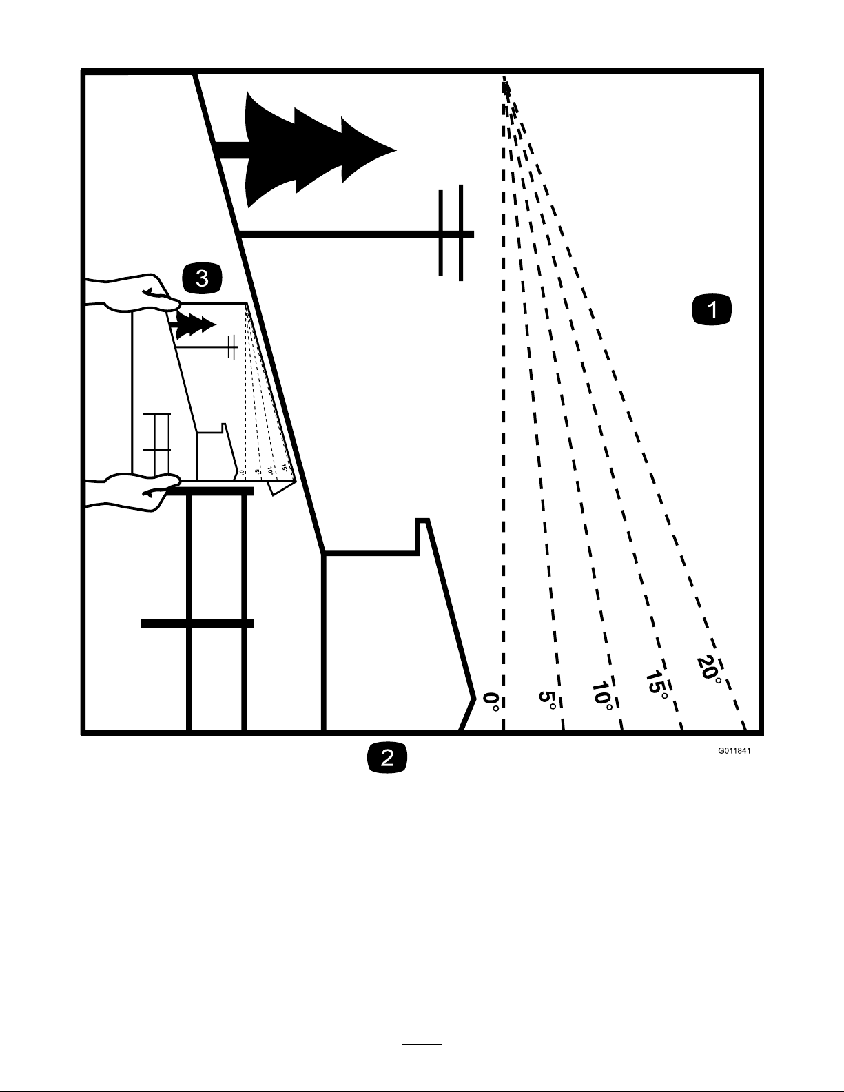
116-0205
109-7232
116-1654
112-3858
1.ReadtheOperator's
Manual.
2.Readtheinstructions
beforeservicingor
performingmaintenance.
1.Main,25A
2.PTO,10A
3.Removetheignitionkey
beforeadjustingtheheight
ofcut.
4.Heightofcutsettings.
116-3303
114-4466
3.Charge,25A
4.Auxiliary,15A
116-4858
9
Page 10
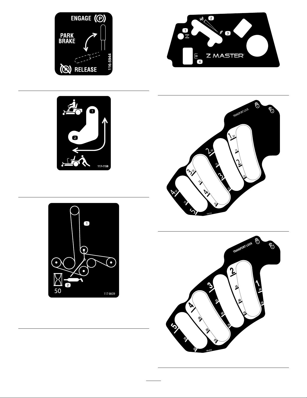
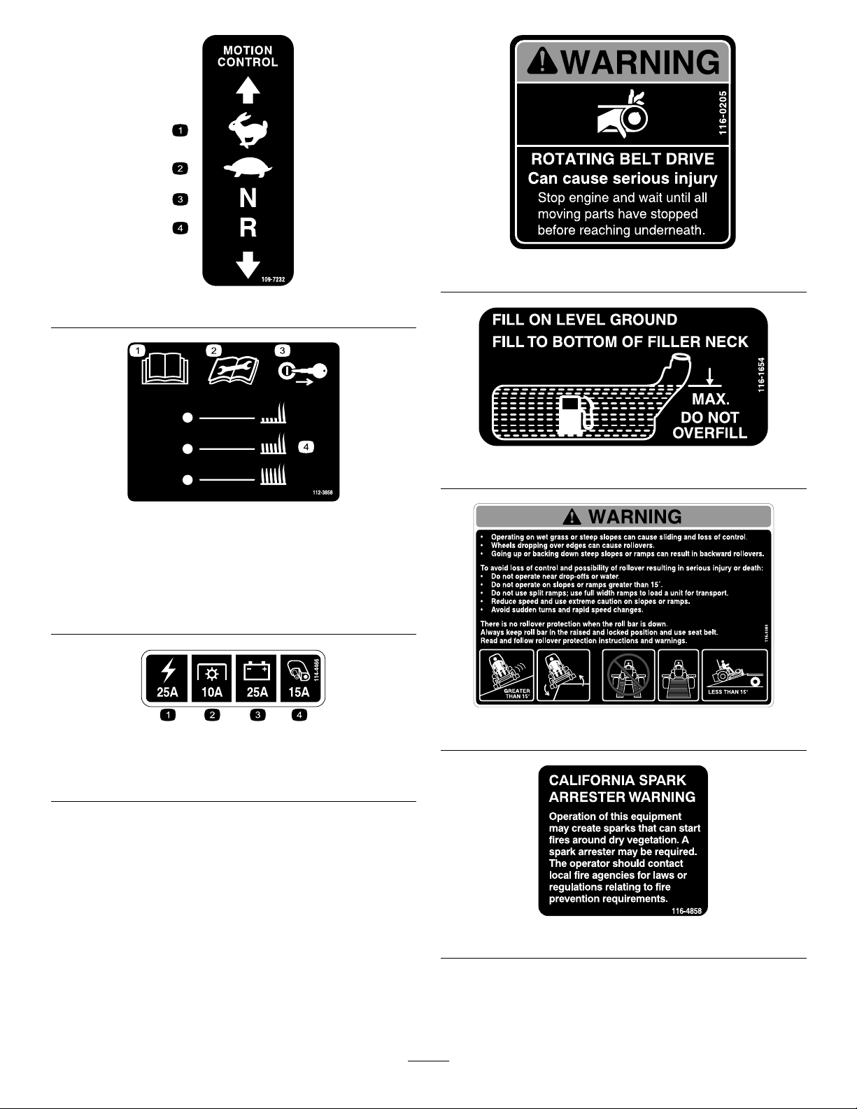
116-5944
117–1158
119-2501
1.Choke3.Slow
2.Fast
4.PTO(PowerT ake-off)
1.Bypassleverpositionfor
operatingthemachine.
1.Beltrouting
2.Bypassleverpositionfor
pushingthemachine.
120-2522
117-8639
2.Greasepulley,
maintenanceinterval—50
hours
120-2532
10
Page 11
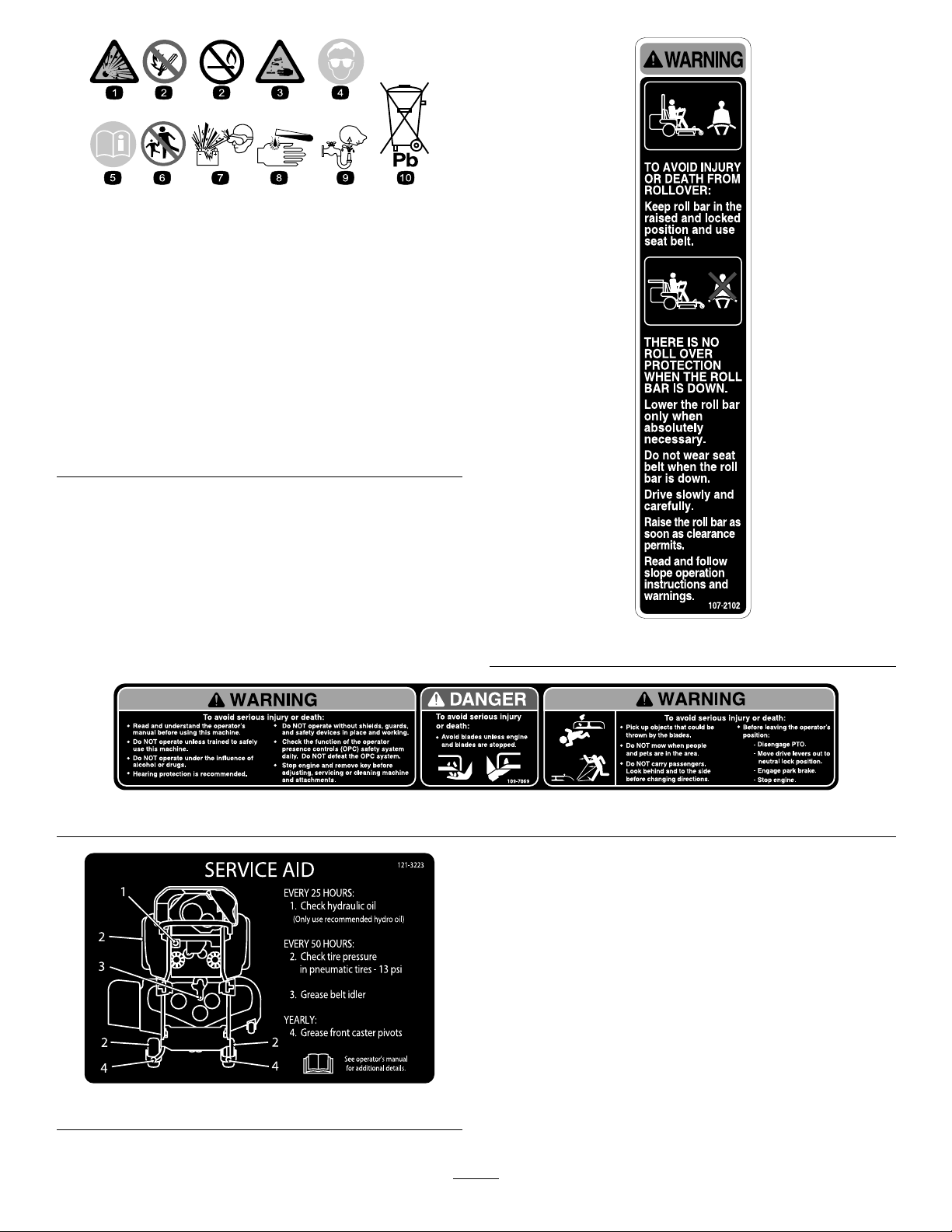
BatterySymbols
Someorallofthesesymbolsareonyourbattery
1.Explosionhazard
2.Nore,opename,or
smoking.
3.Causticliquid/chemical
burnhazard
4.Weareyeprotection9.Flusheyesimmediately
5.ReadtheOperator's
Manual.
6.Keepbystandersasafe
7.Weareyeprotection;
8.Batteryacidcancause
10.Containslead;donot
distancefromthebattery .
explosivegasescan
causeblindnessandother
injuries
blindnessorsevereburns.
withwaterandgetmedical
helpfast.
discard.
107-2102
109-7069
121–3223
11
Page 12
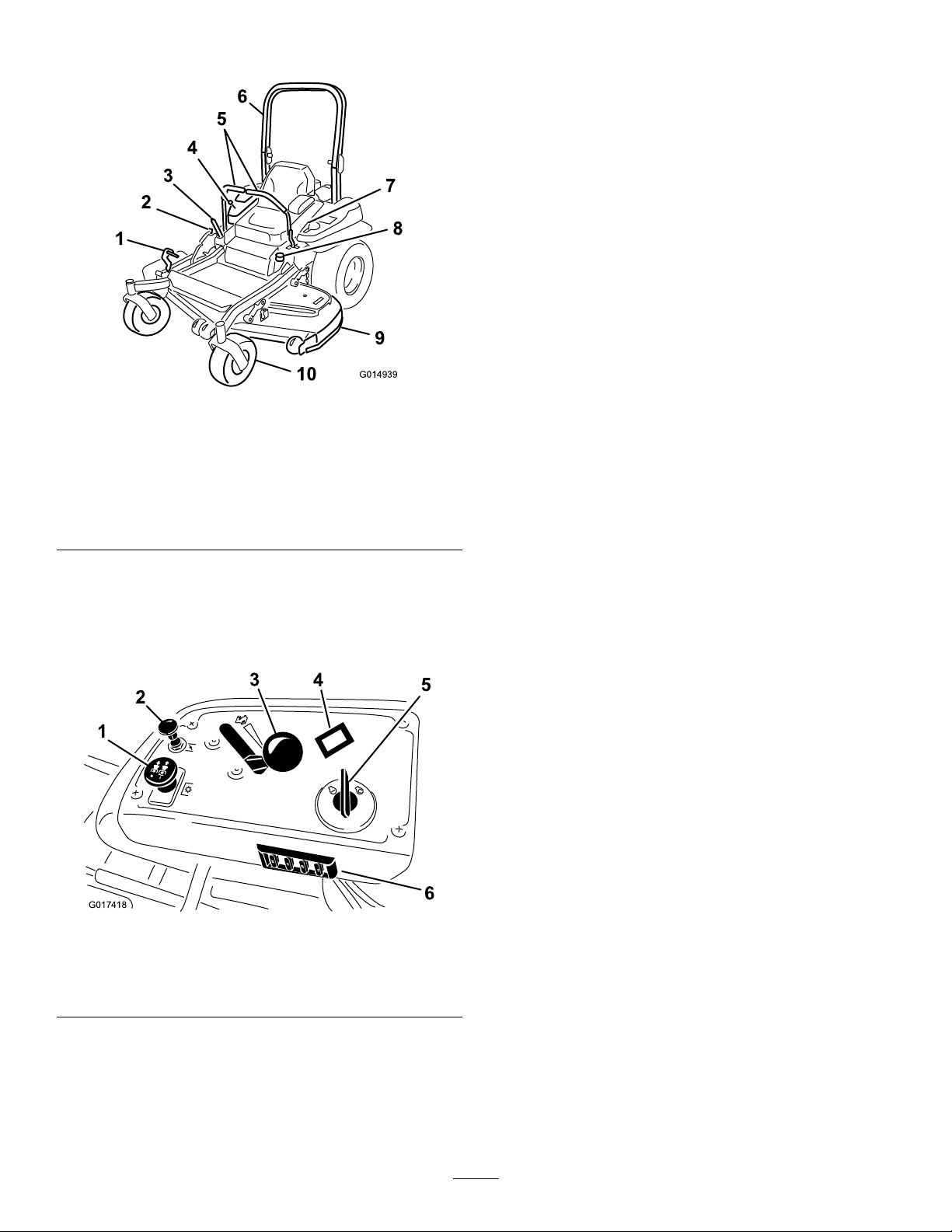
ProductOverview
G014939
G017418
25
25
10
15
1
2
3
4
5
6
Figure4
1.Height-of-cutdeck-lift
pedal
2.Transportlock
3.Parking-brakelever8.Fuelcap
4.Controls
5.Motion-controllevers
6.Rollbar
7.Seatbelt
9.Mowerdeck
10.Casterwheel
HourMeter
Thehourmeterrecordsthenumberofhourstheenginehas
operated.Itoperateswhentheengineisrunning.Usethese
timesforschedulingregularmaintenance(Figure5).
ThrottleControl
ThethrottlecontrolisvariablebetweenFastandSlow.
Choke
Usethechoketostartacoldengine.Pullthechokeknobup
toengageit.
Blade-controlSwitch(PTO)
Theblade-controlswitch(PTO)isusedtoengagetheelectric
clutchanddrivethemowerblades.Pulltheswitchupto
engagethebladesandrelease.Todisengagetheblades,
pushtheblade-controlswitch(PTO)downormovea
motion-controlleverintotheneutral-lockposition.
IgnitionSwitch
Thisswitchisusedtostartthemowerengineandhas3
positions:Start,RunandOff.
Controls
Becomefamiliarwithallthecontrolsbeforeyoustartthe
engineandoperatethemachine(Figure4andFigure5).
Figure5
1.PTOSwitch
2.Choke
3.Throttlecontrol6.Fuses
4.Hourmeter
5.Ignitionswitch
Motion-controlLevers
Themotion-controlleversareusedtodrivethemachine
forward,reverse,andturneitherdirection.
Neutral-lockPosition
Theneutral-lockpositionisusedwiththesafety-interlock
systemtoengageandtodeterminetheneutralposition.
FuelShut-offValve
Closethefuelshut-offvalve(undertheseat)when
transportingorstoringthemower.
Attachments/Accessories
AselectionofToroapprovedattachmentsandaccessoriesis
availableforusewiththemachinetoenhanceandexpand
itscapabilities.ContactyourAuthorizedServiceDealeror
Distributororgotowww .T oro.comforalistofallapproved
attachmentsandaccessories.
12
Page 13

Specications
Note:Specicationsanddesignaresubjecttochangewithoutnotice.
Width:
48-inchDeck52-inchDeck60-inchDeck
WithoutDeck
DeectorUp130.8cm(51.5inches)135.4cm(53.3inches)156.0cm(61.4inches)
DeectorDown160.3cm(63.1inches)171.8cm(67.2inches)191.3cm(75.3inches)
Length:
RollBar-Up
RollBar-Down
Height:
RollBar-UpRollBar-Down
178.3cm(70.2inches)118.1cm(46.5inches)
Weight:
115.1cm(45.3inches)119.4cm(47inches)134.6cm(50.5inches)
48-inchDeck52-inchDeck60-inchDeck
199.6cm(78.6inches)201.7cm(79.4inches)210.8cm(83inches)
204.2cm(80.4inches)206.2cm(81.2inches)215.4cm(84.8inches)
ModelWeight
74141
74143
74145
420kg(926lbs)
428kg(944lbs)
448kg(988lbs)
13
Page 14

Operation
Note:Determinetheleftandrightsidesofthemachine
fromthenormaloperatingposition.
AddingFuel
•Forbestresults,useonlyclean,fresh(lessthan30days
old),unleadedgasolinewithanoctaneratingof87or
higher((R+M)/2ratingmethod).
•Ethanol:Gasolinewithupto10%ethanol(gasohol)
or15%MTBE(methyltertiarybutylether)byvolume
isacceptable.EthanolandMTBEarenotthesame.
Gasolinewith15%ethanol(E15)byvolumeisnot
approvedforuse.Neverusegasolinethatcontains
morethan10%ethanolbyvolume,suchasE15
(contains15%ethanol),E20(contains20%ethanol),or
E85(containsupto85%ethanol).Usingunapproved
gasolinemaycauseperformanceproblemsand/orengine
damagewhichmaynotbecoveredunderwarranty.
•Donotusegasolinecontainingmethanol.
•Donotstorefueleitherinthefueltankorfuelcontainers
overthewinterunlessafuelstabilizerisused.
•Donotaddoiltogasoline.
DANGER
Incertainconditionsduringfueling,static
electricitycanbereleasedcausingasparkwhich
canignitethegasolinevapors.Areorexplosion
fromgasolinecanburnyouandothersandcan
damageproperty.
•Alwaysplacegasolinecontainersontheground
awayfromyourvehiclebeforelling.
•Donotllgasolinecontainersinsideavehicleor
onatruckortrailerbedbecauseinteriorcarpets
orplastictruckbedlinersmayinsulatethe
containerandslowthelossofanystaticcharge.
•Whenpractical,removegas-poweredequipment
fromthetruckortrailerandrefueltheequipment
withitswheelsontheground.
•Ifthisisnotpossible,thenrefuelsuch
equipmentonatruckortrailerfromaportable
container,ratherthanfromagasolinedispenser
nozzle.
•Ifagasolinedispensernozzlemustbeused,
keepthenozzleincontactwiththerimofthe
fueltankorcontaineropeningatalltimesuntil
fuelingiscomplete.
DANGER
Incertainconditions,gasolineisextremely
ammableandhighlyexplosive.Areorexplosion
fromgasolinecanburnyouandothersandcan
damageproperty.
•Fillthefueltankoutdoors,inanopenarea,
whentheengineiscold.Wipeupanygasoline
thatspills.
•Neverllthefueltankinsideanenclosedtrailer.
•Donotllthefueltankcompletelyfull.Add
gasolinetothefueltankuntilthelevelis6to13
mm(1/4to1/2inch)belowthebottomofthe
llerneck.Thisemptyspaceinthetankallows
gasolinetoexpand.
•Neversmokewhenhandlinggasoline,andstay
awayfromanopenameorwheregasoline
fumesmaybeignitedbyaspark.
•Storegasolineinanapprovedcontainerand
keepitoutofthereachofchildren.Neverbuy
morethana30-daysupplyofgasoline.
•Donotoperatewithoutentireexhaustsystemin
placeandinproperworkingcondition.
WARNING
Gasolineisharmfulorfatalifswallowed.Long-term
exposuretovaporscancauseseriousinjuryand
illness.
•Avoidprolongedbreathingofvapors.
•Keepfaceawayfromnozzleandgastankor
conditionerbottleopening.
•Avoidcontactwithskin;washoffspillagewith
soapandwater.
UsingStabilizer/Conditioner
Useafuelstabilizer/conditionerinthemachinetoprovide
thefollowingbenets:
•Keepsgasolinefreshduringstorageof90daysorless.
Forlongerstorageitisrecommendedthatthefueltank
bedrained.
•Cleanstheenginewhileitruns
•Eliminatesgum-likevarnishbuildupinthefuelsystem,
whichcauseshardstarting
Important:Donotusefueladditivescontaining
methanolorethanol.
Addthecorrectamountofgasstabilizer/conditionerto
thegas.
Note:Afuelstabilizer/conditionerismosteffective
whenmixedwithfreshgasoline.Tominimizethechance
14
Page 15
ofvarnishdepositsinthefuelsystem,usefuelstabilizer
g017624
1
2
4
3
5
atalltimes.
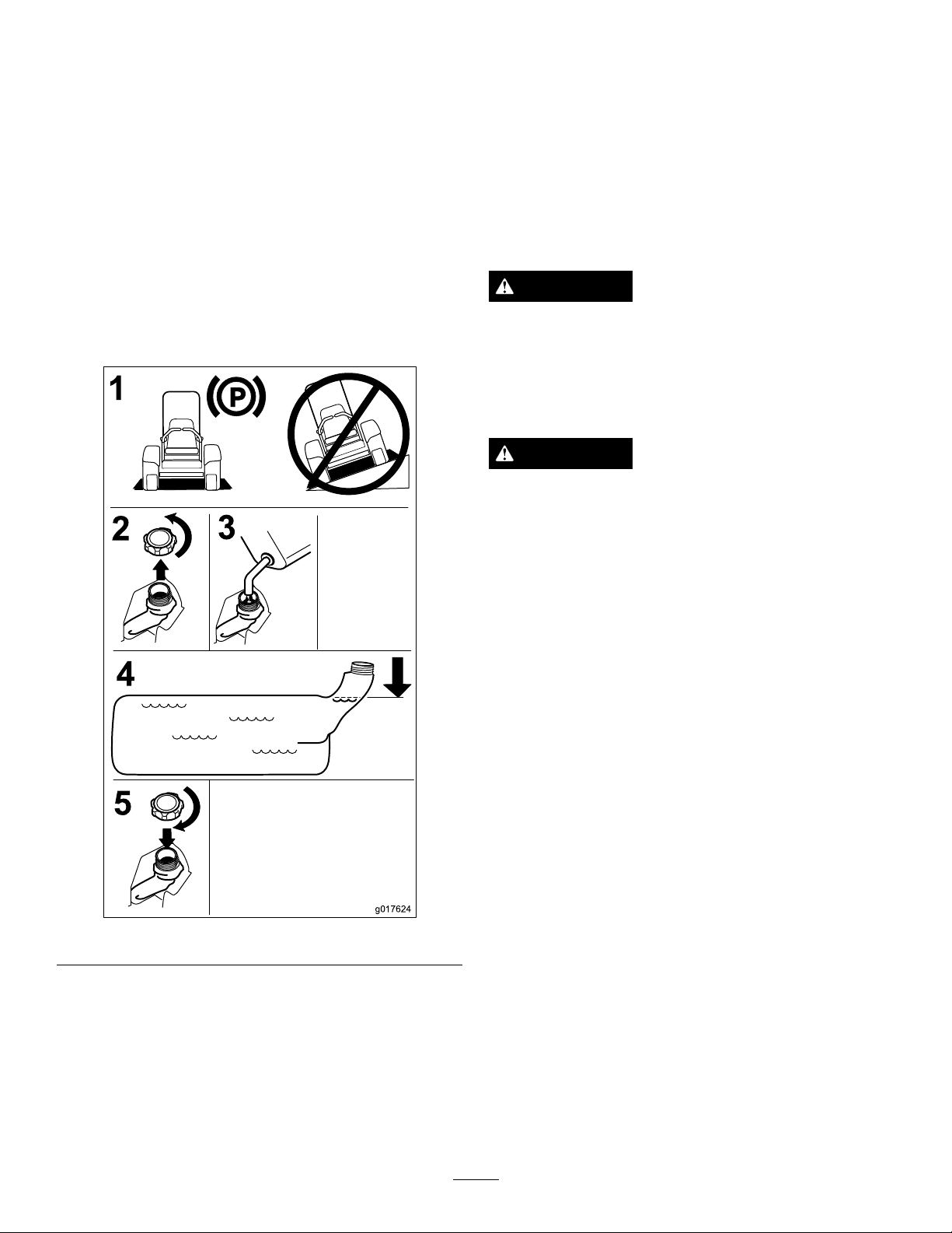
FillingtheFuelTank
Note:Donotllthefueltankcompletelyfull.Fillthefuel
tanktothebottomofthellerneck.Theemptyspaceinthe
tankallowsthegasolinetoexpand.
BreakingInaNewMachine
Newenginestaketimetodevelopfullpower.Mowerdecks
anddrivesystemshavehigherfrictionwhennew,placing
additionalloadontheengine.Allow40to50hoursof
break-intimefornewmachinestodevelopfullpowerand
bestperformance.
1.Parkthemachineonlevelground.
2.Shuttheengineoffandsettheparkingbrake.
3.Cleanaroundthefuel-tankcap.
4.Fillthefueltanktothebottomofthellerneck.
5.Ensurethatthereisemptyspaceinthetanktoallow
thegasolinetoexpand(
Figure6).
UsingtheRollover-Protection System(ROPS)
WARNING
Toavoidinjuryordeathfromrollover:keeptheroll
barinthefullyraisedlockedpositionandusethe
seatbelt.
Ensuretheseatissecuredtothemachine.
WARNING
Thereisnorolloverprotectionwhentherollbaris
inthedownposition.
•Lowertherollbaronlywhenabsolutely
necessary.
•Donotweartheseatbeltwhentherollbaris
inthedownposition.
•Driveslowlyandcarefully.
Figure6
CheckingtheEngine-oilLevel
Beforeyoustarttheengineandusethemachine,checktheoil
levelintheenginecrankcase;referto
Level(page31).
CheckingtheEngine-oil
•Raisetherollbarassoonasclearancepermits.
•Checkcarefullyforoverheadclearances(i.e.
branches,doorways,electricalwires)before
drivingunderanyobjectsanddonotcontact
them.
Important:Lowertherollbaronlywhenabsolutely
necessary.
Important:Ensuretheseatissecuredtothemachine.
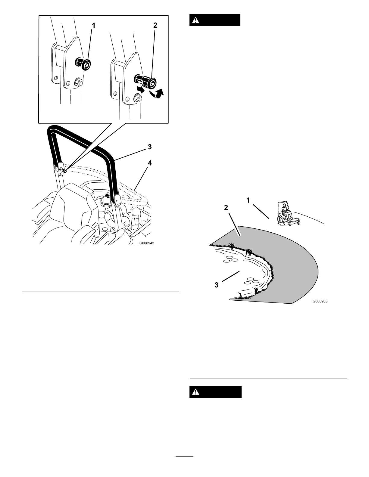
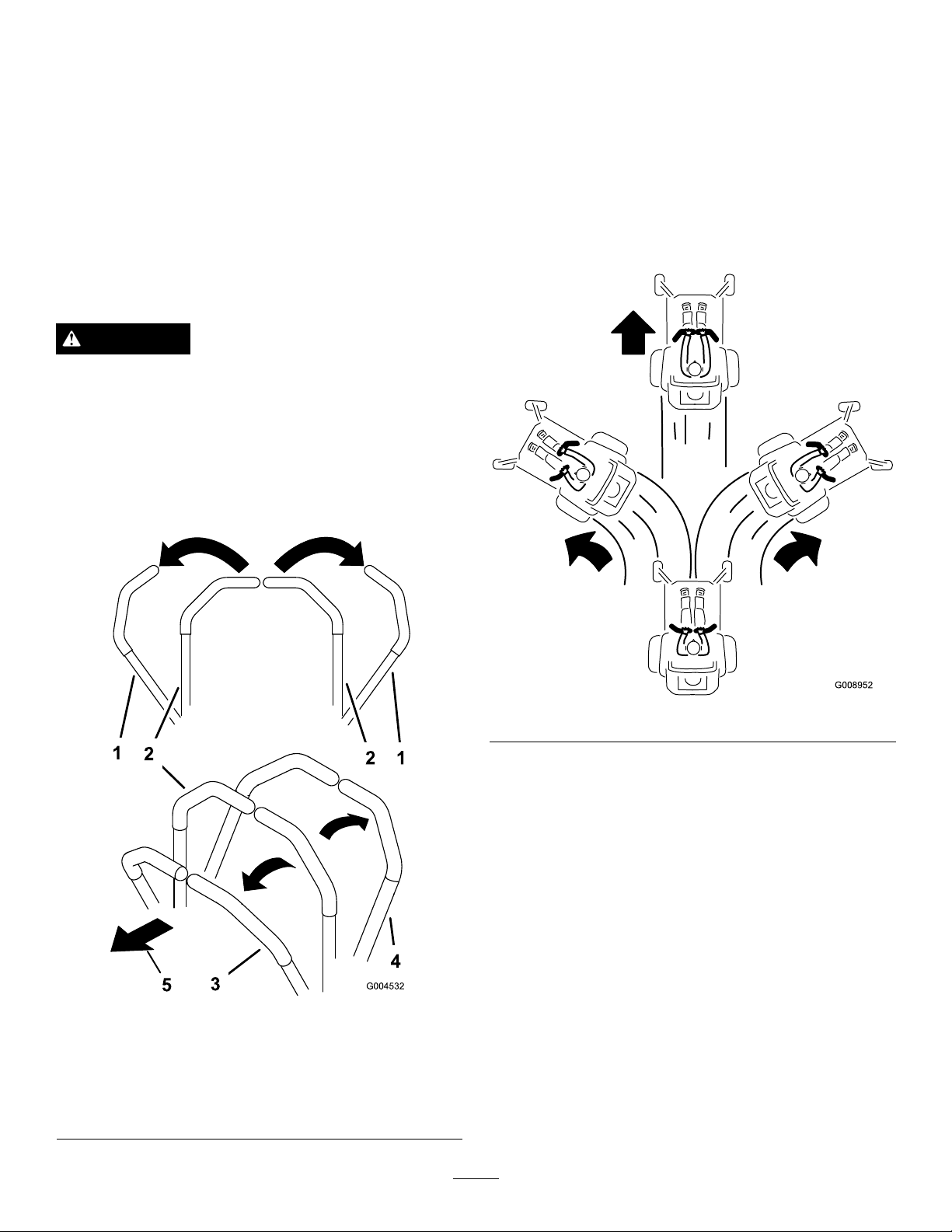
1.Tolowertherollbar,applyforwardpressuretothe
upperpartoftherollbar.
2.Pullbothknobsoutandrotatethem90°sotheyare
notengaged(Figure7).
3.Lowertherollbartothedownposition(Figure7).
15
Page 16
DANGER
Operatingonwetgrassorsteepslopescancause
slidingandlossofcontrol.
Wheelsdroppingoveredgescancauserollovers,
whichmayresultinseriousinjury,deathor
drowning.
Thereisnorolloverprotectionwhentherollbaris
down.
Alwayskeeptherollbarintheraisedandlocked
positionandusetheseatbelt.
Readandfollowtherolloverprotectioninstructions
andwarnings.
Toavoidlossofcontrolandpossibilityofrollover:
•Donotoperateneardrop-offsornearwater.
•Donotoperateonslopesgreaterthan15degrees.
•Reducespeedanduseextremecautionon
slopes.
•Avoidsuddenturnsorrapidspeedchanges.
Figure7
1.ROPSknob
2.PullROPSknoboutand
rotate90degrees
3.Rollbarintheupright
position
4.Rollbarinthefolded
position
4.Toraisetherollbar,raisetherollbartotheoperate
position,rotatetheknobssothattheymovepartially
intothegrooves(Figure7).
5.Raisetherollbartothefulluprightpositionwhile
pushingontheupperrollbarandthepinswillsnapinto
positionwhentheholesalignwiththepins(Figure7).
Important:Alwaysusetheseatbeltwiththeroll
barintheraisedposition.
6.Pushontherollbarandensurethatbothpinsare
engaged.
ThinkSafetyFirst
Pleasereadallsafetyinstructionsandsymbolsinthesafety
section.Knowingthisinformationcouldhelpyouor
bystandersavoidinjury.
Figure8
1.SafeZone—usethe
ZMasterhereonslopes
lessthan15degreesor
atareas.
2.DangerZone—usea
walk-behindmowerand/or
ahandtrimmeronslopes
greaterthan15degrees,
neardrop-offsandwater.
3.Water
CAUTION
Thismachineproducessoundlevelsinexcessof
85dBAattheoperatorsearandcancausehearing
lossthroughextendedperiodsofexposure.
Wearhearingprotectionwhenoperatingthis
machine.
16
Page 17
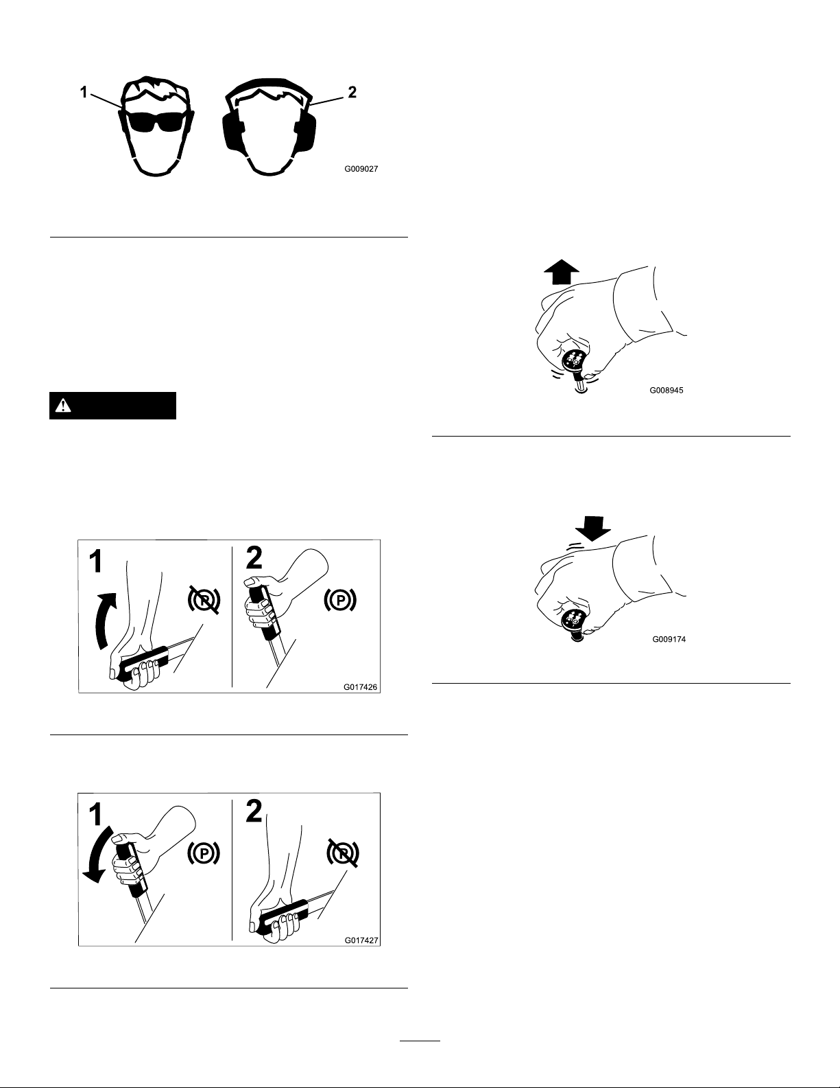
Theuseofprotectiveequipmentforeyes,ears,feet,andhead
G009027
1
2
G017426
1
2
G017427
1
2
G008945
G009174
isrecommended.
Figure9
1.Wearsafetyglasses
2.Wearhearingprotection
OperatingtheParkingBrake
Alwayssettheparkingbrakewhenyoustopthemachineor
leaveitunattended.
SettingtheParkingBrake
OperatingtheMower Blade-controlSwitch(PTO)
Theblade-controlswitch(PTO)startsandstopsthemower
bladesandanypoweredattachments.
EngagingtheBlade-controlSwitch
(PTO)
Note:Engagingtheblade-controlswitch(PTO)withthe
throttlepositionathalforlesswillcauseexcessivewearto
thedrivebelts.
WARNING
Parkingbrakemaynotholdmachineparkedona
slopeandcouldcausepersonalinjuryorproperty
damage.
Donotparkonslopesunlesswheelsarechocked
orblocked
Figure10
ReleasingtheParkingBrake
Figure12
DisengagingtheBlade-controlSwitch
(PTO)
Figure13
Figure11
17
Page 18
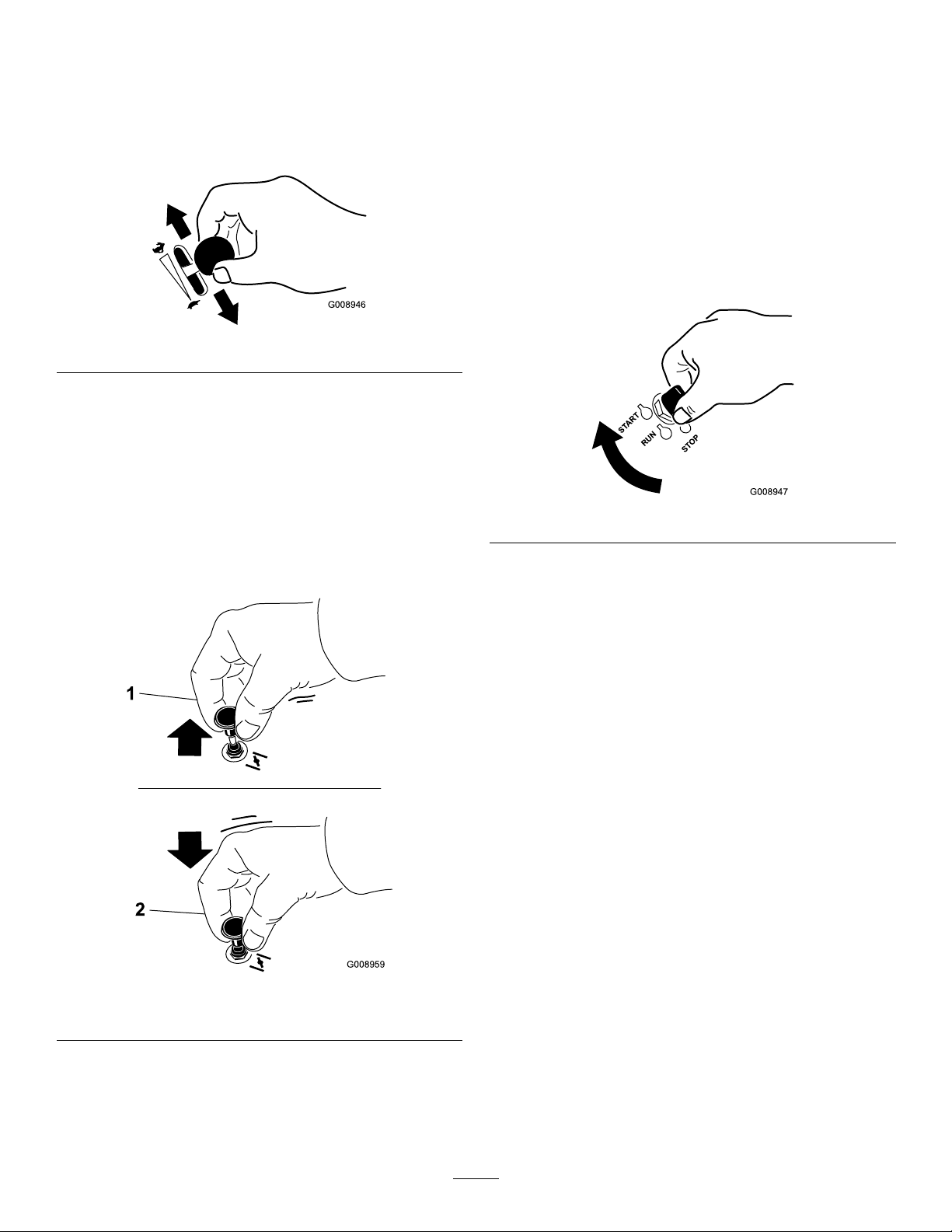
OperatingtheThrottle
G008946
G008959
1
2
START
RUN
STOP
G008947
OperatingtheIgnitionSwitch
ThethrottlecontrolcanbemovedbetweenFastandSlow
positions(Figure14).
AlwaysusetheFastpositionwhenturningonthemower
deckwiththeblade-controlswitch(PTO).
Figure14
OperatingtheChoke
Usethechoketostartacoldengine.
1.Iftheengineiscold,usethechoketostarttheengine.
2.Pulluponthechokeknobtoengagethechokebefore
usingtheignitionswitch(Figure15).
1.TurntheignitionkeytotheStartposition(Figure16).
Note:Whentheenginesstarts,releasethekey.
Important:Donotengagestarterformorethan5
secondsatatime.Iftheenginefailstostartallow
a15secondcool-downperiodbetweenattempts.
Failuretofollowtheseinstructionscanburnout
thestartermotor.
Note:Additionalstartingcyclesmayberequired
whenstartingtheengineforthersttimeafterthefuel
systemhasbeenwithoutfuelcompletely.
Figure16
3.Pushdownonthechoketodisengagethechokeafter
theenginehasstarted(
Figure15).
2.Turntheignitionkeytostoptostoptheengine.
Figure15
1.Onposition2.Offposition
18
Page 19
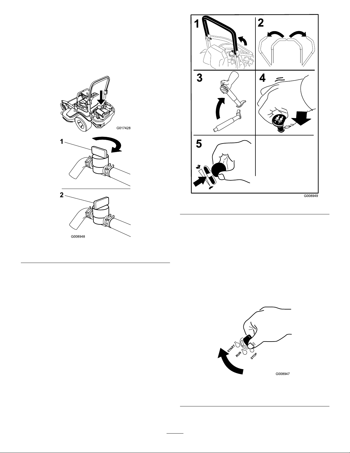
UsingtheFuelShut-offValve
G017428
G008948
1
2
START
RUN
STOP
G008947
Thefuelshut-offvalveislocatedbehindtheseat.
Closethefuelshut-offvalvefortransport,maintenance,and
storage.
Ensurethatthefuelshut-offvalveisopenwhenstartingthe
engine.
Figure18
6.TurntheignitionkeytotheStartposition(Figure19).
Note:Whentheenginesstarts,releasethekey.
Figure17
1.Onposition2.Offposition
Important:Donotengagestarterformorethan5
secondsatatime.Iftheenginefailstostartallow
a15secondcool-downperiodbetweenattempts.
Failuretofollowtheseinstructionscanburnout
thestartermotor.
StartingandStoppingthe Engine
Note:Additionalstartingcyclesmayberequired
whenstartingtheengineforthersttimeafterthefuel
systemhasbeenwithoutfuelcompletely.
StartingtheEngine
1.RaisetheROPSupandlockintoplace,sitontheseat,
andfastentheseatbelt.
2.Movethemotioncontrolstoneutral-lockedposition.
3.Settheparkingbrake;referto
Brake(page17).
4.Movetheblade-controlswitch(PTO)totheOff
position(Figure18).
5.MovethethrottlelevermidwaybetweentheSlowand
Fastpositions.
SettingtheParking
Figure19
1.Off3.Start
2.Run
19
Page 20
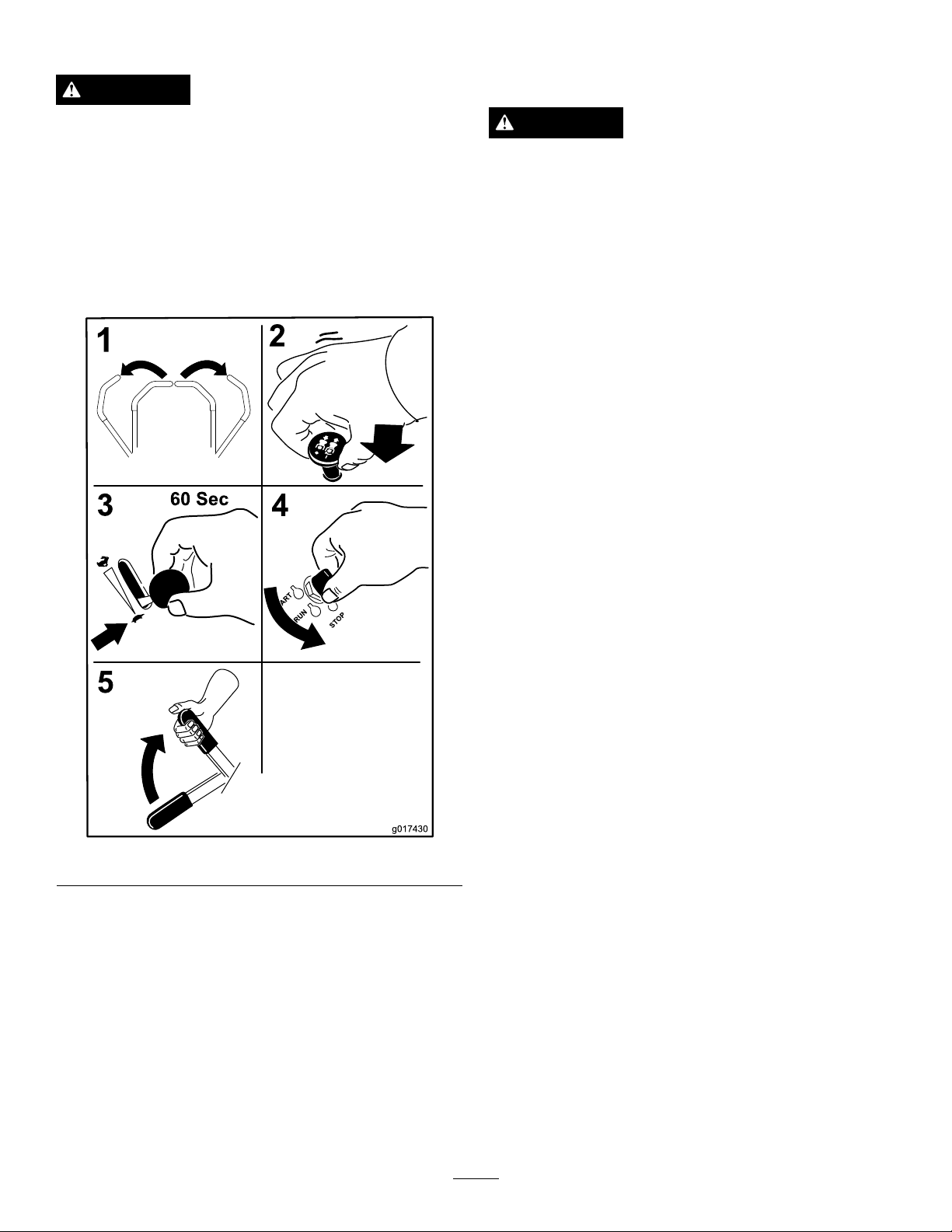
StoppingtheEngine
g017430
UsingtheSafety-interlock
CAUTION
Childrenorbystandersmaybeinjuredifthey
moveorattempttooperatethemachinewhileitis
unattended.
Alwaysremovetheignitionkeyandsettheparking
brakewhenleavingthemachineunattended,even
ifjustforafewminutes.
Lettheengineidleatslowthrottle(turtle)for60seconds
beforeturningtheignitionswitchoff.
System
CAUTION
Ifsafety-interlockswitchesaredisconnectedor
damagedthemachinecouldoperateunexpectedly
causingpersonalinjury.
•Donottamperwiththeinterlockswitches.
•Checktheoperationoftheinterlockswitches
dailyandreplaceanydamagedswitchesbefore
operatingthemachine.
UnderstandingtheSafety-interlock
System
Thesafety-interlocksystemisdesignedtopreventtheengine
fromstartingunless:
•Theparkingbrakeisengaged.
•Theblade-controlswitch(PTO)isdisengaged.
•Themotion-controlleversareintheneutral-locked
position.
Thesafety-interlocksystemalsoisdesignedtostopthe
enginewhenthetractioncontrolsaremovedfromthelocked
positionwiththeparkingbrakeengagedorifyourisefrom
theseatwhenthePTOisengaged.
Figure20
Important:Makesurethatthefuelshut-offvalveis
closedbeforetransportingorstoringthemachine,as
fuelleakagemayoccur.Settheparkingbrakebefore
transporting.Makesuretoremovethekeyasthefuel
pumpmayrunandcausethebatterytolosecharge.
TestingtheSafety-interlockSystem
ServiceInterval:Beforeeachuseordaily
Testthesafety-interlocksystembeforeyouusethemachine
eachtime.Ifthesafetysystemdoesnotoperateasdescribed
below,haveanAuthorizedServiceDealerrepairthesafety
systemimmediately.
1.Sittingontheseat,engagetheparkingbrakeandmove
theblade-controlswitch(PTO)totheOnposition.
Trystartingtheengine;theengineshouldnotcrank.
2.Sittingontheseat,engagetheparkingbrakeandmove
theblade-controlswitch(PTO)totheOffposition.
Moveeithermotion-controllever(outofneutrallocked
position).Trystartingtheengine;theengineshould
notcrank.Repeatforothercontrollever.
3.Sittingontheseat,engagetheparkingbrake,move
theblade-controlswitch(PTO)totheOffposition,
andmovethemotion-controlleverstoneutral-lock
position.Nowstarttheengine.Whiletheengine
isrunning,releasetheparkingbrake,engagethe
blade-controlswitch(PTO)andriseslightlyfromthe
seat;theengineshouldstop.
4.Sittingontheseat,engagetheparkingbrake,move
theblade-controlswitch(PTO)totheOffposition,
andmovethemotion-controlleverstoneutral-lock
position.Nowstarttheengine.Whiletheengine
isrunning,centereithermotioncontrolandmove
20
Page 21
(forwardorreverse);theengineshouldstop.Repeat
G008952
forothermotioncontrol.
5.Sittingontheseat,disengagetheparkingbrake,move
theblade-controlswitch(PTO)totheOffposition,
andmovethemotion-controlleverstoneutral-lock
position.Trystartingtheengine;theengineshould
notcrank.
DrivingForward
Note:Theenginewillkillifthetraction-controlleversare
movedwiththeparkingbrakeengaged.
Tostop,pullthemotion-controlleverstotheneutralposition.
1.Releasetheparkingbrake;refertoReleasingthe
ParkingBrake(page17).
DrivingForwardorBackward
Thethrottlecontrolregulatestheenginespeedasmeasured
inrpm(revolutionsperminute).Placethethrottlecontrolin
theFastpositionforbestperformance.Alwaysoperateinthe
fullthrottlepositionwhenmowing.
CAUTION
Machinecanspinveryrapidly.Operatormaylose
controlofmachineandcausepersonalinjuryor
damagetomachine.
•Usecautionwhenmakingturns.
•Slowthemachinedownbeforemakingsharp
turns.
UsingtheMotion-controlLevers
2.Movetheleverstothecenter,unlockedposition.
3.Togoforward,slowlypushthemotion-controllevers
forward(Figure22).
Figure21
1.Motion-control
lever—neutral-lock
position
2.Center,unlockedposition5.Frontofmachine
3.Forward
4.Backward
Figure22
21
Page 22

DrivingBackward
G008953
1.Movetheleverstothecenter,unlockedposition.
2.Togobackward,slowlypullthemotion-controllevers
rearward(Figure23).
Figure23
StoppingtheMachine
Tostopthemachine,movethetraction-controlleversto
neutral,andthenmovethemtothelockedposition,disengage
thepowertakeoff(blade-controlswitch(PTO),andturnthe
ignitionkeytotheOffposition.
Settheparkingbrakewhenyouleavethemachine;referto
SettingtheParkingBrake(page17).Remembertoremove
thekeyfromtheignitionswitch.
CAUTION
Childrenorbystandersmaybeinjuredifthey
moveorattempttooperatethemachinewhileitis
unattended.
Alwaysremovetheignitionkeyandsettheparking
brakewhenleavingthemachineunattended,even
ifjustforafewminutes.
AdjustingtheHeight-of-Cut
UsingtheTransportLock
Thetransportlockhas2positions,andisusedwiththe
deck-liftpedal.Thereisalockpositionandaunlockposition
forthetransportposition.Thetransportlockisusedwith
thedeck-liftpedal(
Figure24).
Figure24
Transport-LockPositions
1.Transportlock3.Unlockposition—doesnot
lockthemowerdeckinto
transportposition
2.Lockposition—mower
deckwilllockintotransport
position
22
Page 23
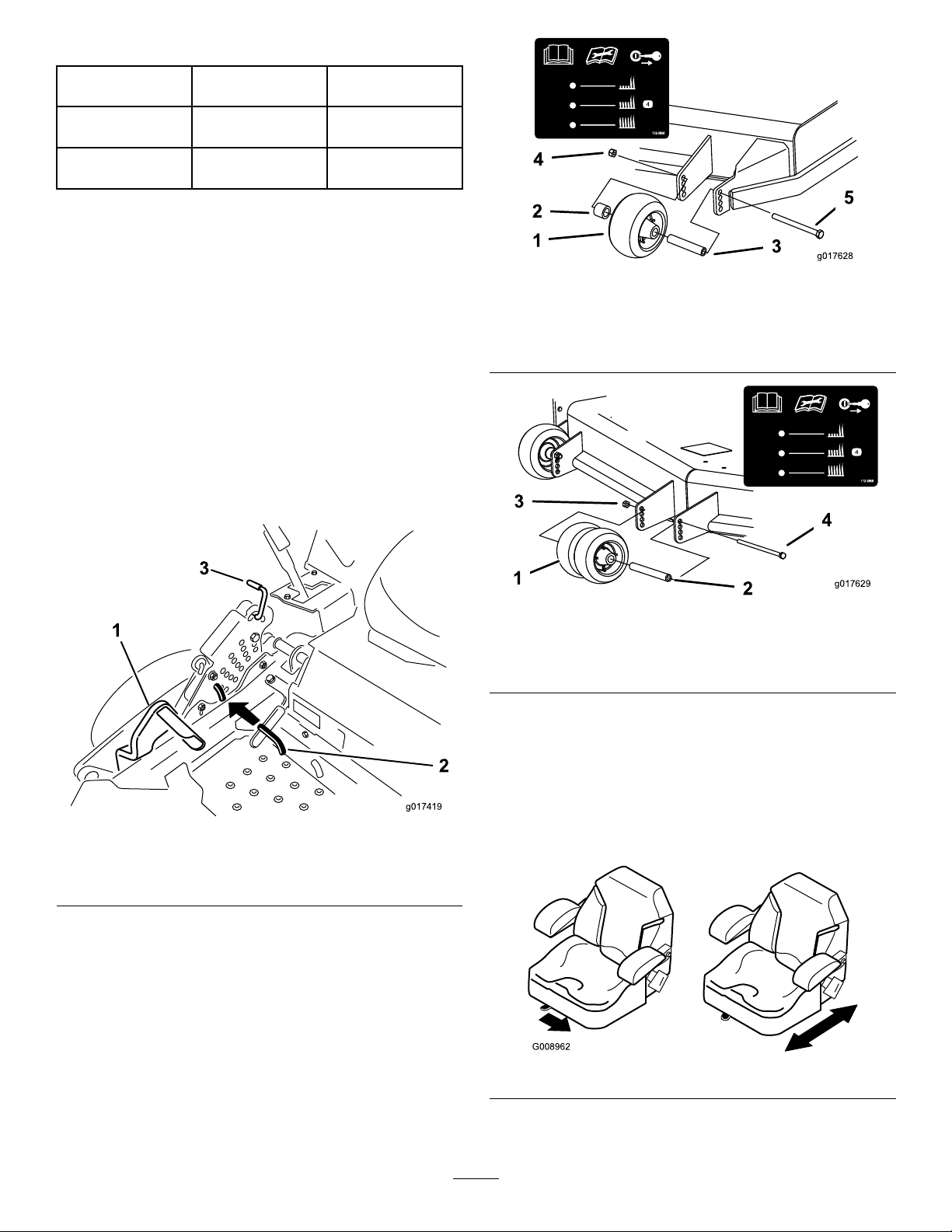
AdjustingtheHeight-of-CutPin
g017419
2
1
3
g017628
g017629
G008962
Mowerdecksize
48-inchdeck
52-inchand60-inch
decks
Height-of-cut
range
38to127mm(1-1/2
to5inches)
38to140mm(1-1/2
to5-1/2inches)
Increments
6mm(1/4inch)
6mm(1/4inch)
Theheight-of-cutisadjustedfrom25to140mm(1to
5-1/2inches)in6mm(1/4inch)incrementsbyrelocating
theclevispinintodifferentholelocations.
1.Movethetransportlocktothelockposition.
2.Pushonthedeck-liftpedalwithyourfoot,andraisethe
mowerdecktothetransportposition(alsothe140mm
(5-1/2inches)cuttingheightposition)asshownin
Figure25.
3.Toadjust,rotatethepin90degreesandremovethepin
fromtheheight-of-cutbracket(
Figure25).
4.Selectaholeintheheight-of-cutbracketcorresponding
totheheight-of-cutdesired,andinsertthepin(Figure
25).
5.Pushonthedecklift,pullbackonthetransportlock,
andslowlylowerthemowerdeck.
Figure26
1.Anti-scalproller4.Flangenut
2.Spacer
3.Bushing
5.Bolt
Figure25
1.Deck-liftpedal
2.Cut-of-heightpin
3.Transportlock
AdjustingtheAnti-scalp Rollers
Wheneveryouchangetheheight-of-cut,itisrecommended
toadjusttheheightoftheanti-scalprollers.
1.Disengagetheblade-controlswitch(PTO),movethe
2.Stoptheengine,removethekey ,andwaitforallmoving
motion-controlleverstotheneutral-lockedposition,
andsettheparkingbrake.
partstostopbeforeleavingtheoperatingposition.
Figure27
1.Anti-scalproller3.Flangenut
2.Bushing4.Bolt
PositioningtheSeat
Theseatcanmoveforwardandbackward.Positiontheseat
whereyouhavethebestcontrolofthemachineandaremost
comfortable.
Toadjust,movetheleversidewaystounlockseat(Figure28).
Figure28
23
Page 24
UsingtheDrive-wheel-release
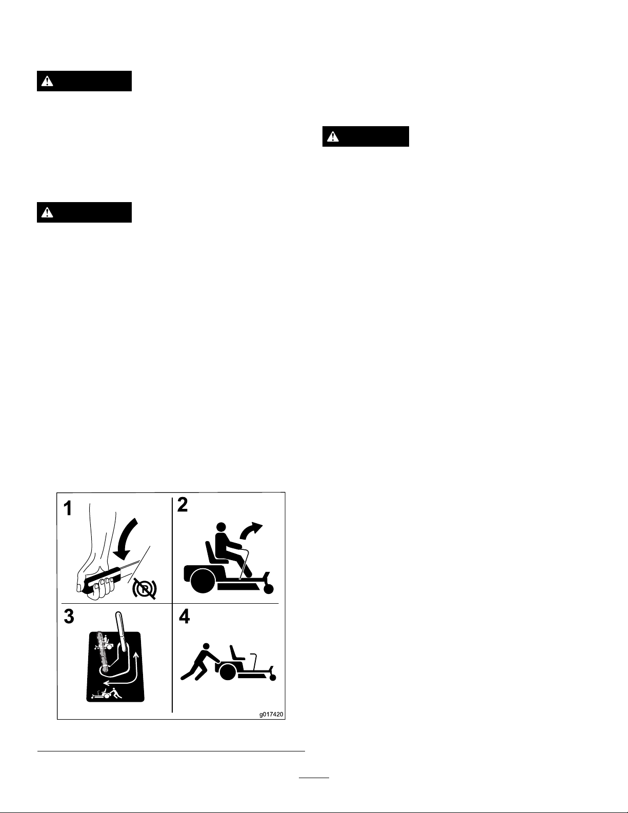
g017420
2
3
4
1
6.Torunthemachine,movethebypassleverstothe
forwardposition(Figure29).
Valves
WARNING
Handsmaybecomeentangledintherotatingdrive
componentsbelowtheenginedeck,whichcould
resultinseriousinjury.
Stoptheengine,removethekey,andallow
allmovingpartstostopbeforeaccessingthe
drive-wheel-releasevalves.
WARNING
Theengineandhydraulic-driveunitscanbecome
veryhot.Touchingahotengineorhydraulic-drive
unitscancausesevereburns.
Allowtheengineandhydraulic-driveunitstocool
completelybeforeaccessingthedrive-wheel-release
valves.
Thedrive-wheel-releasevalvesarelocatedbehindtheseatand
downintheenginecompartment.
1.DisengagethePTO(blade-controlswitch),turnthe
ignitionkeytooff,movetheleverstotheneutral-locked
position,applytheparkingbrake,andremovethekey .
2.Locatethebypassleversbehindtheseat,downonthe
leftandrightsideoftheframe.
3.Topushthemachine,movethebypassleversrearward
andouttolockthemintoplace(Figure29).
4.Repeatthisoneachsideofthemachine.
5.Disengageparkingbrakebeforepushing.
UsingtheSideDischarge
Themowerhasahingedgrassdeectorthatdisperses
clippingstothesideanddowntowardtheturf.
DANGER
Withoutagrassdeector,dischargecover,ora
completegrass-catcherassemblymountedin
place,youandothersareexposedtobladecontact
andthrowndebris.Contactwithrotatingmower
blade(s)andthrowndebriswillcauseinjuryor
death.
•Neverremovethegrassdeectorfromthemower
becausethegrassdeectorroutesmaterialdown
towardtheturf.Ifthegrassdeectorisever
damaged,replaceitimmediately .
•Neverputyourhandsorfeetunderthemower.
•Nevertrytoclearthedischargeareaormower
bladesunlessyoumovethepowertakeoff
(blade-controlswitch(PTO)totheOffposition,
rotatetheignitionkeytotheOffposition,and
removethekey.
•Makesurethegrassdeectorisinthedown
position.
LoadingMachines
Useextremecautionwhenloadingunitsontrailersortrucks.
Onefull-widthrampthatiswideenoughtoextendbeyond
thereartiresisrecommendedinsteadofindividualrampsfor
eachsideoftheunit(Figure30).Thelower,rearsectionof
themachineframeextendsbackbetweentherearwheels,and
servesasastopfortippingbackward.Havingafull-width
rampprovidesasurfacefortheframememberstocontactif
theunitstartstotipbackward.Ifitisnotpossibletouseone
full-widthramp,useenoughindividualrampstosimulatea
full-widthcontinuousramp.
Figure29
Therampshouldbelongenoughsothattheanglesdonot
exceed15degrees(Figure30).Asteeperanglemaycause
mowercomponentstogetcaughtastheunitmovesfrom
ramptotrailerortruck.Steeperanglesmayalsocausethe
unittotipbackward.Ifloadingonornearaslope,position
thetrailerortrucksoitisonthedownsideoftheslopeand
therampextendsuptheslope.Thiswillminimizetheramp
angle.Thetrailerortruckshouldbeaslevelaspossible.
Important:Donotattempttoturntheunitwhileonthe
ramp;youmaylosecontrolanddriveofftheside.
Avoidsuddenaccelerationwhendrivinguparampand
suddendecelerationwhenbackingdownaramp.Both
maneuverscancausetheunittotipbackward.
24
Page 25

WARNING
TransportingMachines
Loadingaunitontoatrailerortruckincreasesthe
possibilityofbackwardtip-overandcouldcause
seriousinjuryordeath.
•Useextremecautionwhenoperatingauniton
aramp.
•EnsuretheROPSisintheuppositionwhile
usingtheseatbeltwhenloadingthemachine.
EnsuretheROPSwillclearthetopofan
enclosedtrailer.
•Useonlyasingle,full-widthramp;donotuse
individualrampsforeachsideoftheunit.
•Ifindividualrampsmustbeused,useenough
rampstocreateanunbrokenrampsurfacewider
thantheunit.
•Donotexceeda15-degreeanglebetweenramp
andgroundorbetweentherampandtraileror
truck.
•Avoidsuddenaccelerationwhiledrivingunitup
aramptoavoidtippingbackward.
•Avoidsuddendecelerationwhilebackingunit
downaramptoavoidtippingbackward.
Useaheavy-dutytrailerortrucktotransportthemachine.
Ensurethatthetrailerortruckhasallthenecessarybrakes,
lighting,andmarkingasrequiredbylaw.Pleasecarefullyread
allthesafetyinstructions.Knowingthisinformationcould
helpyou,yourfamily,petsorbystandersavoidinjury.
WARNING
Drivingonthestreetorroadwaywithoutturn
signals,lights,reectivemarkings,oraslow
movingvehicleemblemisdangerousandcanlead
toaccidentscausingpersonalinjury.
Donotdrivemachineonapublicstreetorroadway .
Totransportthemachine:
1.Ifusingatrailer,connectittothetowingvehicle,and
connectthesafetychains.
2.Ifapplicable,connectthetrailerbrakes.
3.Loadthemachineontothetrailerortruck.
4.Stoptheengine,removethekey,setthebrake,and
closethefuelvalve.
5.Usethemetaltie-downloopsonthemachineto
securelyfastenthemachinetothetrailerortruckwith
straps,chains,cable,orropes(
Figure31).
Figure30
1.Trailer3.Notgreaterthan
15degrees
2.Full-widthramp4.Full-widthramp—side
view
Figure31
1.Tractionunittie-downloops
25
Page 26

OperatingTips
UsingtheFastThrottleSetting
Forbestmowingandmaximumaircirculation,operate
theengineattheFastthrottleposition.Airisrequiredto
thoroughlycutgrassclippings,sodonotsettheheight-of-cut
solowastototallysurroundthemowerbyuncutgrass.
Alwaystrytohaveonesideofthemowerfreefromuncut
grass,whichallowsairtobedrawnintothemower.
CuttingaLawnfortheFirstTime
Cutgrassslightlylongerthannormaltoensurethatthe
cuttingheightofthemowerdoesnotscalpanyuneven
ground.However,thecuttingheightusedinthepastis
generallythebestonetouse.Whencuttinggrasslongerthan
sixinchestall,youmaywanttocutthelawntwicetoensure
anacceptablequalityofcut.
Cutting1/3oftheGrassBlade
CuttingLongGrass
Ifthegrassiseverallowedtogrowslightlylongerthan
normal,orifitcontainsahighdegreeofmoisture,raisethe
cuttingheighthigherthanusualandcutthegrassatthis
setting.Thencutthegrassagainusingthelower,normal
setting.
Stopping
Ifthemachine'sforwardmotionmustbestoppedwhile
mowing,aclumpofgrassclippingsmaydropontoyourlawn.
Toavoidthis,moveontoapreviouslycutareawiththeblades
engaged.
KeepingtheUndersideoftheMower
Clean
Cleanclippingsanddirtfromtheundersideofthemower
aftereachuse.Ifgrassanddirtbuildupinsidethemower,
cuttingqualitywilleventuallybecomeunsatisfactory.
Itisbesttocutonlyabout1/3ofthegrassblade.Cutting
morethanthatisnotrecommendedunlessgrassissparse,or
itislatefallwhengrassgrowsmoreslowly.
AlternatingtheMowingDirection
Alternatemowingdirectiontokeepthegrassstanding
straight.Thisalsohelpsdisperseclippingswhichenhances
decompositionandfertilization.
MowingatCorrectIntervals
Normally,moweveryfourdays.Butremember,grassgrows
atdifferentratesatdifferenttimes.Sotomaintainthesame
cuttingheight,whichisagoodpractice,mowmoreoftenin
earlyspring.Asthegrassgrowthrateslowsinmidsummer,
mowlessfrequently .Ifyoucannotmowforanextended
period,rstmowatahighcuttingheight;thenmowagain
twodayslateratalowerheightsetting.
AdjustingtheCuttingSpeed
Toimprovecutquality ,useaslowergroundspeedincertain
conditions.
MaintainingtheBlade
Maintainasharpbladethroughoutthecuttingseasonbecause
asharpbladecutscleanlywithouttearingorshreddingthe
grassblades.Tearingandshreddingturnsgrassbrownat
theedges,whichslowsgrowthandincreasesthechanceof
disease.Checkthecutterbladesdailyforsharpness,andfor
anywearordamage.Filedownanynicksandsharpenthe
bladesasnecessary.Ifabladeisdamagedorworn,replaceit
immediatelywithagenuineTOROreplacementblade.
AvoidingCuttingTooLow
Ifthecuttingwidthofthemoweriswiderthanthemower
youpreviouslyused,raisethecuttingheighttoensurethat
uneventurfisnotcuttooshort.
26
Page 27

Maintenance
RecommendedMaintenanceSchedule(s)
MaintenanceService
Interval
Aftertherst8hours
Aftertherst50hours
Beforeeachuseordaily
Every25hours
Every50hours
Every100hours
Every200hours
MaintenanceProcedure
•Changetheengineoil.
•Checkthetorqueonthewheellugnuts.
•Changethehydraulic-systemlterandoil.
•Checkthesafetysystem.
•Checktheengine-oillevel.
•Checktheseatbelt.
•Checktherollover-protection-system(ROPS)knobs.
•Cleantheenginescreen.
•Inspecttheblades.
•Cleanthemowerdeck.
•Checkthehydraulic-oillevelintheexpansiontank.
•Greasethemowerdeckidlerarm.
•Checksparkarrester(ifequipped).
•Checkthetirepressure.
•Inspectthebeltsforcracksandwear.
•Lubricatethemowerdeck-liftpivots.
•Changetheengineoil(moreoftenindirtyordustyconditions).
•Check,cleanandregapthesparkplug.
•Checkandcleanenginecoolingnsandshrouds.
•Changetheengine-oillter.
Every250hours
Every400hours
Every500hours
Monthly
Yearly
Yearlyorbeforestorage
•Replacetheprimaryairlter(moreoftenindustyorsandyconditions).
•Checkthesafetyairlter.
•Changethehydraulic-systemlterandoil.
•Replacethesafetyairlter.
•Replacethefuellter(moreoftenindirtyordustyconditions).
•Adjustthecaster-pivotbearing.
•Checktheelectricclutch.
•Checkthebatterycharge.
•Greasethefrontcasterpivots(moreoftenindirtyordustyconditions).
•Lubricatethecaster-wheelhubs.
•Checkthetorqueonthewheellugnuts.
•Paintchippedsurfaces.
•Checkallmaintenanceprocedureslistedabovebeforestorage.
Important:Refertoyourengineoperator'smanualforadditionalmaintenanceprocedures.
CAUTION
Ifyouleavethekeyintheignitionswitch,someonecouldaccidentlystarttheengineandseriouslyinjure
youorotherbystanders.
Removethekeyfromtheignitionbeforeyoudoanymaintenance.
27
Page 28

Lubrication
g017421
g017435
g014942
GreasingandLubrication
Greasemorefrequentlywhenoperatingconditionsare
extremelydustyorsandy .
GreaseType:No.2general-purposelithiumbaseor
molybdenum-basegrease
1.Disengagetheblade-controlswitch(PTO),movethe
motion-controlleverstotheneutral-lockedposition,
andsettheparkingbrake.
2.Stoptheengine,removethekey ,andwaitforallmoving
partstostopbeforeleavingtheoperatingposition.
3.Cleanthegreasettingswitharag.
Note:Makesuretoscrapeanypaintoffthefrontof
thetting(s).
4.Connectagreaseguntothetting,andpumpgrease
intothettingsuntilgreasebeginstooozeoutofthe
bearings.
5.Wipeupanyexcessgrease.
GreasingtheMower
ServiceInterval:Every50hours—Greasethemowerdeck
idlerarm.
Yearly—Greasethefrontcasterpivots(moreoftenin
dirtyordustyconditions).
1.Disengagetheblade-controlswitch(PTO),movethe
motion-controlleverstotheneutral-lockedposition,
andsettheparkingbrake.
2.Stoptheengine,removethekey ,andwaitforallmoving
partstostopbeforeleavingtheoperatingposition.
3.Greasethemowerdeckidler-pulleypivotuntilgrease
comesoutofthebottom(
Figure33).
AddingLightOilorSprayingon
Lubrication
ServiceInterval:Every100hours
Lubricatethedeck-liftpivots.
Figure33
4.Removethedustcapandadjustthecasterpivots.
Note:Keepthedustcapoffuntilgreasingisdone;
refertoAdjustingtheCaster-pivotBearing(page39).
5.Removethehexplug.
6.Threadagreasettingintothehole.
7.Pumpgreaseintothettinguntilitoozesoutaround
thetopbearing.
8.Removethegreasettinginthehole.
9.Installthehexpluganddustcap(
Figure34).
Figure32
Figure34
28
Page 29
LubricatingtheCaster-wheel Hubs
ServiceInterval:Yearly
1.Stoptheengine,waitforallmovingpartstostop,
removethekey ,andengagetheparkingbrake.
Figure35
14.Torquethenutto8to9N-m(75to80in-lb),loosen,
thentorqueto2to3N-m(20to25in-lb).
Note:Makesureaxledoesnotextendbeyondeither
nut.
15.Installthesealguardsoverthewheelhub,andinsert
wheelintothecasterfork.
16.Installthecasterboltandtightenthenutfully.
Important:Topreventsealandbearingdamage,check
thebearingadjustmentoften.Spinthecastertire.The
tireshouldnotspinfreely(morethan1or2revolutions)
orhaveanysideplay.Ifthewheelspinsfreely,adjustthe
torqueonthespacernutuntilthereisaslightamountof
drag.Applyanotherlayerofthread-lockingadhesive.
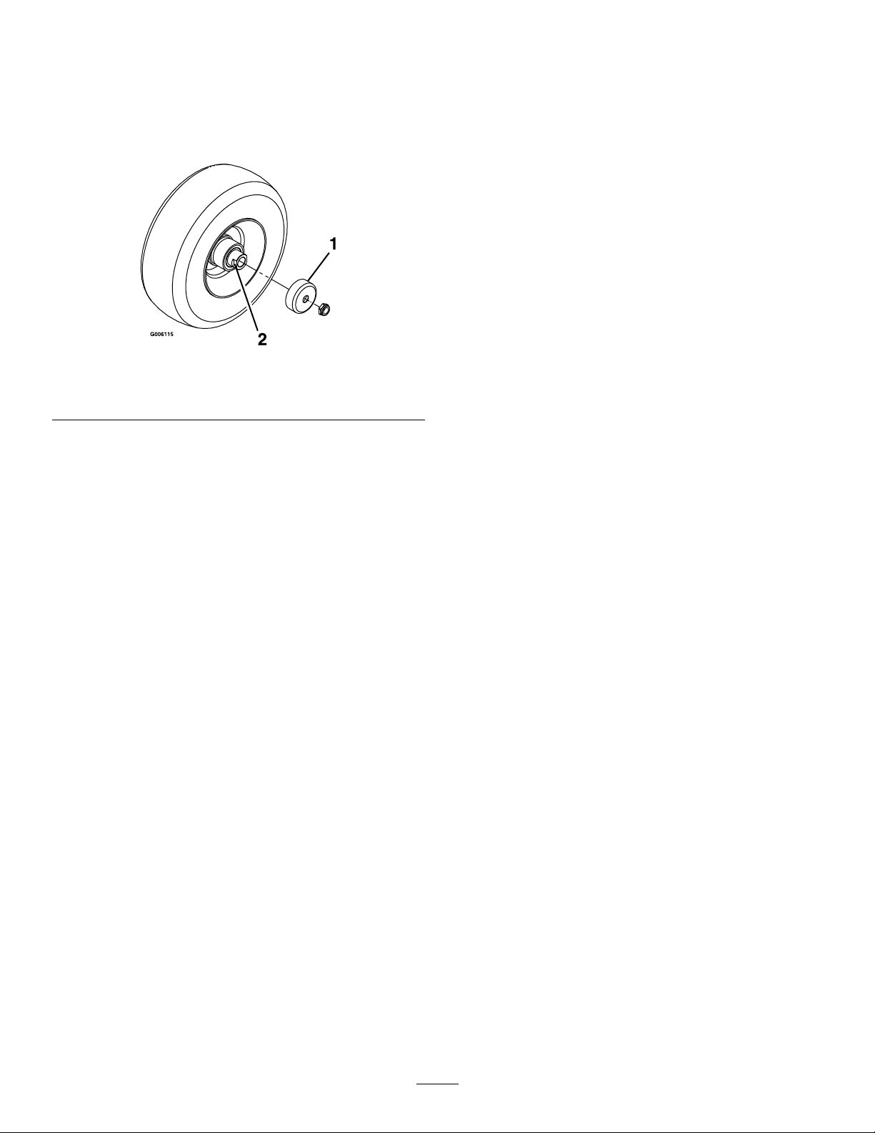
1.Sealguard2.Spacernutwithwrench
2.Removethecasterwheelfromthecasterforks.
3.Removethesealguardsfromthewheelhub.
4.Removeoneofthespacernutsfromtheaxleassembly
inthecasterwheel.
Note:Thread-lockingadhesivehasbeenappliedto
lockthespacernutstotheaxle.
5.Removetheaxle(withtheotherspacernutstill
assembledtoit)fromthewheelassembly .
6.Pryoutsealsandinspectbearingsforwearordamage
andreplaceifnecessary.
7.Packthebearingswithageneral-purposegrease.
8.Insert1bearingand1newsealintothewheel.
Note:Thesealsmustbereplaced.
9.Iftheaxleassemblyhashadbothspacernutsremoved
(orbrokenloose),applyathread-lockingadhesiveto1
spacernut,andthreaditontotheaxlewiththewrench
atsfacingoutward.
ats
Note:Donotthreadthespacernutalloftheway
ontotheendoftheaxle.Leaveapproximately3mm
(1/8inch)fromtheoutersurfaceofthespacernutto
theendoftheaxleinsidethenut.
10.Inserttheassemblednutandaxleintothewheelonthe
sideofthewheelwiththenewsealandbearing.
11.Withtheopenendofthewheelfacingup,llthearea
insidethewheelaroundtheaxlefullofgeneral-purpose
grease.
12.Insertthesecondbearingandnewsealintothewheel.
13.Applyathread-lockingadhesivetothesecondspacer
nut,andthreaditontotheaxlewiththewrenchats
facingoutward.
29
Page 30
EngineMaintenance
WARNING
Contactwithhotsurfacesmaycausepersonal
injury.
Keephands,feet,face,clothingandotherbody
partsawaythemuferandotherhotsurfaces.
6.Removethesafetylteronlyifyouintendtoreplaceit.
Important:Donotattempttocleanthesafety
lter.Ifthesafetylterisdirty,thentheprimary
lterisdamaged.Replacebothlters.
7.Inspecttheprimarylterfordamagebylookinginto
thelterwhileshiningabrightlightontheoutsideof
thelter.Holesinthelterwillappearasbrightspots.
Ifthelterisdamaged,discardit.
ServicingtheAirCleaner
ServiceInterval:Every250hours—Replacetheprimary
airlter(moreoftenindustyorsandy
conditions).
Every250hours—Checkthesafetyairlter.
Every500hours—Replacethesafetyairlter.
Note:Checktheltersmorefrequentlyiftheoperating
conditionsareextremelydustyorsandy.
RemovingtheFilters
1.DisengagethePTO,movethemotion-controlleversto
theneutral-lockedposition,andsettheparkingbrake.
2.Stoptheengine,removethekey ,andwaitforallmoving
partstostopbeforeleavingtheoperatingposition.
3.Releasethelatchesontheaircleanerandpullthe
air-cleanercoverofftheair-cleanerbody(
Figure36).
ServicingthePrimaryFilter
•Iftheprimarylterisdirty,bent,ordamaged,replaceit.
•Donotcleantheprimarylter.
ServicingtheSafetyFilter
Replacethesafetylter,nevercleanit.
Important:Donotattempttocleanthesafetylter.
Ifthesafetylterisdirty,thentheprimarylteris
damaged.Replacebothlters.
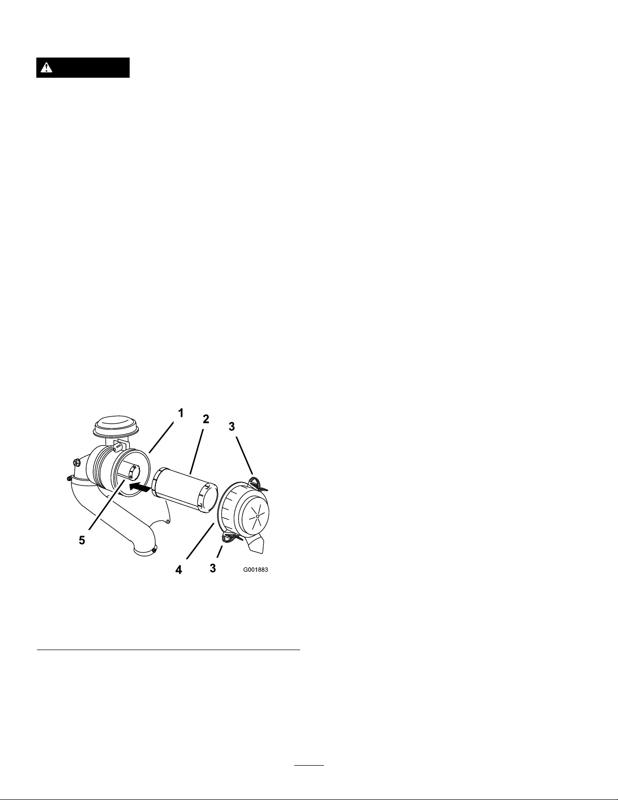
InstallingtheFilters
Important:T opreventenginedamage,alwaysoperate
theenginewithbothairltersandthecoverinstalled.
1.Ifinstallingnewlters,checkeachlterforshipping
damage.
Note:Donotuseadamagedlter.
2.Ifthesafetylterisbeingreplaced,carefullyslideit
intothelterbody(
Figure36).
Figure36
1.Air-cleanerbody4.Air-cleanercover
2.Primarylter5.Safetylter
3.Latch
4.Cleantheinsideoftheair-cleanercoverwith
compressedair.
5.Gentlyslidetheprimarylteroutoftheair-cleaner
body(Figure36).
Note:Avoidknockingthelterintothesideofthe
body.
3.Carefullyslidetheprimarylteroverthesafetylter
(Figure36).
Note:Ensurethattheprimarylterisfullyseatedby
pushingonitsouterrimwhileinstallingit.
Important:Donotpressonthesoftinsidearea
ofthelter.
4.Installtheair-cleanercoverwiththesideindicatedas
upfacingupwardandsecurethelatches(Figure36).
30
Page 31

ServicingtheEngineOil
G008804
G008792
1
2
5
6
7
3
9
10
4
8
OilType:Detergentoil(APIserviceSF ,SG,SH,SJ,orSL)
CrankcaseCapacity:withalterchange,2.1L(71oz);
withoutalterchange,1.8L(61oz)
Viscosity:Seethetablebelow.
Figure37
Note:Useofmulti-gradeoils(5W-20,10W -30,or10W-40)
willincreaseoilconsumption.Checktheoillevelmore
frequentlywhenusingthem.
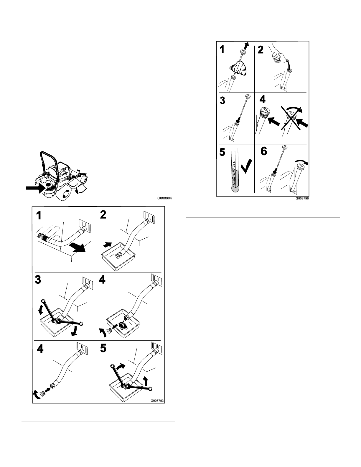
CheckingtheEngine-oilLevel
ServiceInterval:Beforeeachuseordaily
Note:Checktheoilwhentheengineiscold.
WARNING
Contactwithhotsurfacesmaycausepersonal
injury.
Keephands,feet,face,clothing,andotherbody
partsawayfromthemuferandotherhotsurfaces.
Important:Donotoverllthecrankcasewithoil
becausedamagetotheenginemayresult.Donotrun
enginewithoilbelowtheLowmarkbecausetheengine
maybedamaged.
1.DisengagethePTO,movethemotion-controlleversto
theneutral-lockedposition,andsettheparkingbrake.
Figure38
2.Stoptheengine,removethekey,andwaitforall
movingpartstostopbeforeleavingtheoperating
position(
Figure38).
31
Page 32
ChangingtheEngineOil
G008804
G008793
1
2
3
4
4
5
G008796
2
3
4
5
6
1
ServiceInterval:Aftertherst8hours
Every100hours(moreoftenindirtyordusty
conditions).
Note:Disposeoftheusedoilatarecyclingcenter.
1.Starttheengineandletitrunfor5minutes.
Note:Thiswarmstheoilsoitdrainsbetter.
2.Parkthemachinesothattherearisslightlylowerthan
thefronttoensurethattheoildrainscompletely .
3.DisengagethePTO,movethemotion-controlleversto
theneutral-lockedposition,andsettheparkingbrake.
4.Stoptheengine,removethekey,andwaitforall
movingpartstostopbeforeleavingtheoperating
position(
Figure39).
5.Slowlypourapproximately80%ofthespeciedoil
intothellertubeandslowlyaddtheadditionaloilto
bringittotheFullmark(Figure40).
Figure40
6.Starttheengineanddrivetoaatarea.
7.Checktheoillevelagain.
Figure39
32
Page 33
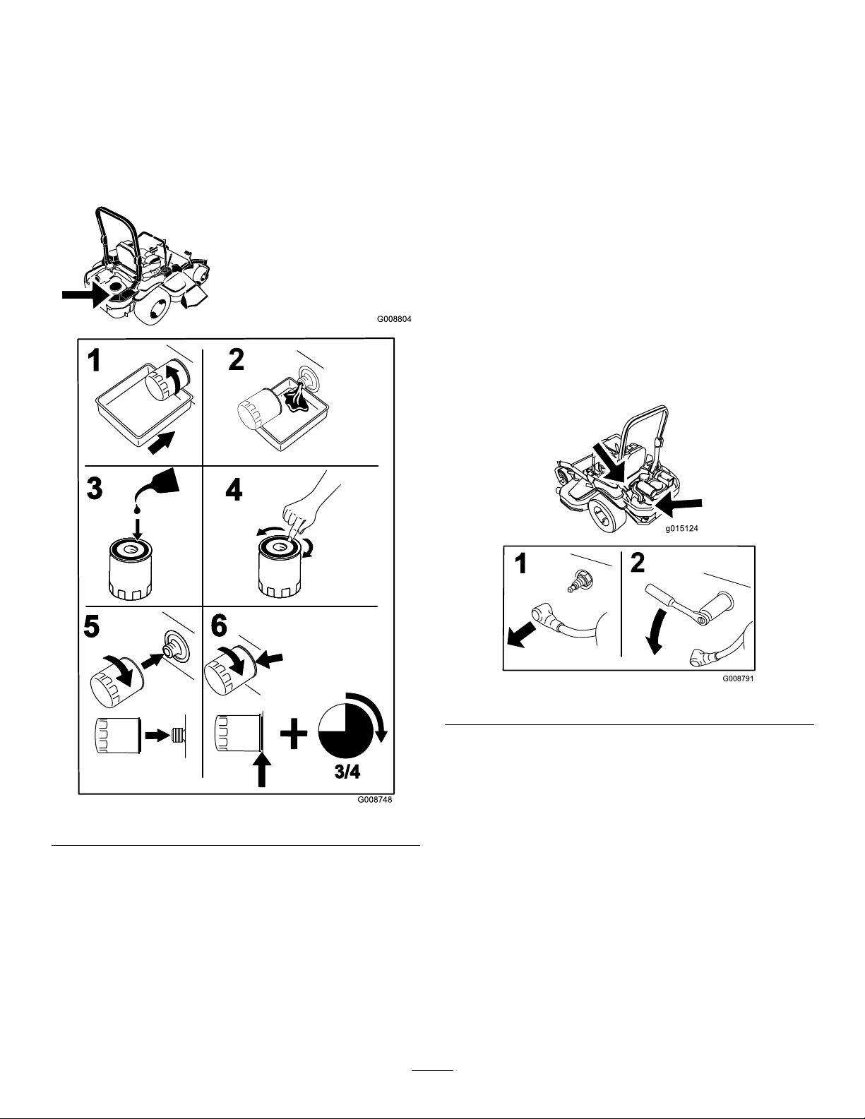
ChangingtheEngine-oilFilter
G008804
G008748
3/4
1
2
3
4
5
6
g015124
ServicingtheSparkPlug
ServiceInterval:Every200hours
Note:Changetheengine-oilltermorefrequentlywhen
operatingconditionsareextremelydustyorsandy.
1.Draintheoilfromtheengine;refertoChangingthe
EngineOil(page32).
2.Changetheengine-oillter(
Figure41).
ServiceInterval:Every100hours
Makesuretheairgapbetweenthecenterandsideelectrodes
iscorrectbeforeinstallingthesparkplug.Useasparkplug
wrenchforremovingandinstallingthesparkplug(s)anda
gappingtool/feelergaugetocheckandadjusttheairgap.
Installanewsparkplug(s)ifnecessary.
TypeofSparkPlug:NGK
AirGap:0.75mm(0.03inch)
®
BPR4ESorequivalent
RemovingtheSparkPlug
1.Stoptheengine,removethekey ,andwaitforallmoving
partstostopbeforeleavingtheoperatingposition.
2.DisengagethePTO,movethemotion-controlleversto
theneutral-lockedposition,andsettheparkingbrake.
3.Locateandremovethesparkplugs(
Figure42).
Note:Ensuretheoil-ltergaskettouchestheengine,
andthenanextra3/4turniscompleted.
3.Fillthecrankcasewiththepropertypeofnewoil;refer
to
ChangingtheEngineOil(page32).
Figure41
Figure42
33
Page 34
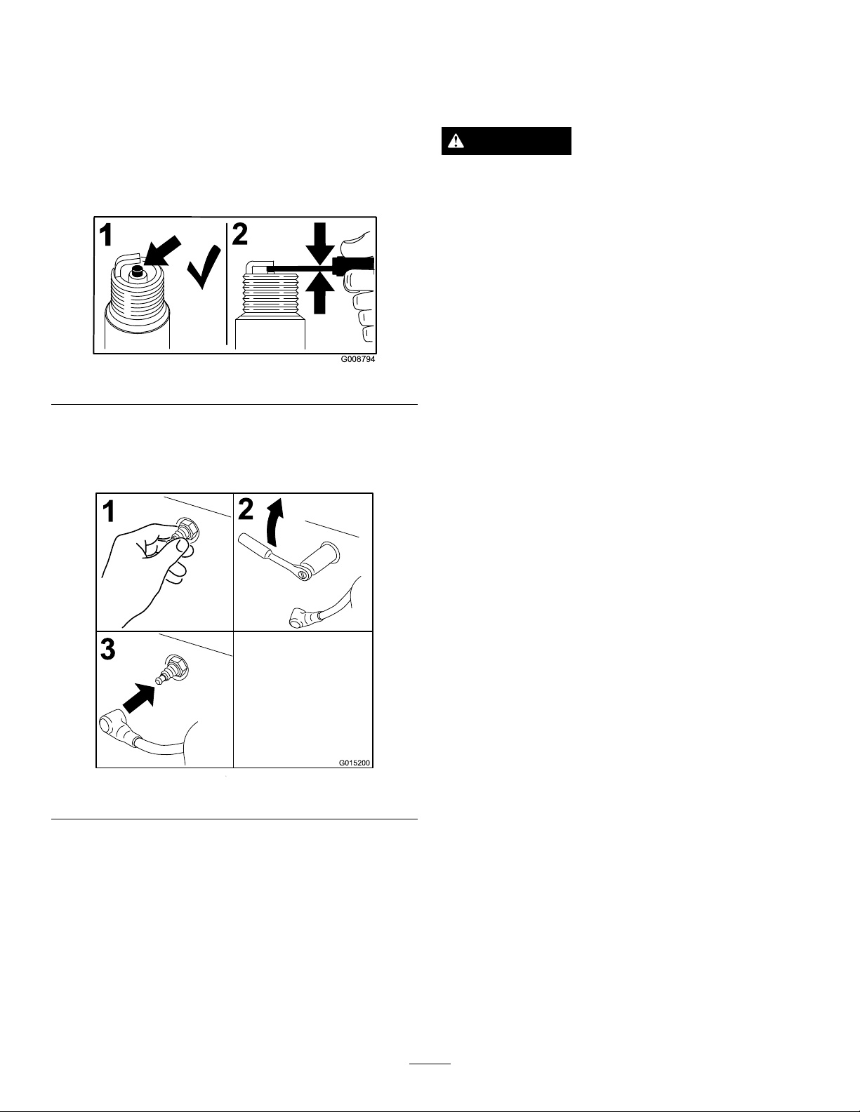
CheckingtheSparkPlug
G008794
1
2
3
2
1
G015200
CheckingtheSparkArrester
Important:Donotcleanthesparkplug(s).Always
replacethesparkplug(s)whenithas:ablackcoating,
wornelectrodes,anoilylm,orcracks.
Ifyouseelightbrownorgrayontheinsulator,theengineis
operatingproperly.Ablackcoatingontheinsulatorusually
meanstheaircleanerisdirty.
Setthegapto0.76mm(0.03inch).
Figure43
InstallingtheSparkPlug
Tightenthesparkplug(s)to22N-m(16ft.-lb).
(ifequipped)
ServiceInterval:Every50hours
WARNING
Hotexhaustsystemcomponentsmayignite
gasolinevaporsevenaftertheengineisstopped.
Hotparticlesexhaustedduringengineoperation
mayigniteammablematerials.Firemayresultin
personalinjuryorpropertydamage.
Donotfuelorrunengineunlesssparkarresteris
installed.
1.Stopengine,waitforallmovingpartstostop,remove
thekey ,andengagetheparkingbrake.
2.Waitformufertocool.
3.Ifthereareanybreaksinthescreenorweldsare
observed,replacethearrester.
4.Ifpluggingofthescreenisobserved,removethe
arresterandshakelooseparticlesoutofthearrester,
andcleanscreenitwithawirebrush(soakinsolvent
ifnecessary).
5.Installarresteronexhaustoutlet.
Figure44
34
Page 35

FuelSystem
G008963
12
3
ServicingtheFuelTank
Maintenance
ReplacingtheFuelFilter
ServiceInterval:Every500hours/Yearly(whichevercomes
rst)(moreoftenindirtyordusty
conditions).
Thefuellterislocatedneartheengineonthefrontorrear
sideoftheengine.
1.DisengagethePTO,movethemotion-controlleversto
theneutral-lockedposition,andsettheparkingbrake.
2.Stoptheengine,removethekey ,andwaitforallmoving
partstostopbeforeleavingtheoperatingposition.
3.Allowthemachinetocooldown.
4.Stoptheengine,removethekey ,andwaitforallmoving
partstostopbeforeleavingtheoperatingposition.
5.Closethefuel-shutoffvalveundertheseat(
Figure45).
Donotattempttodrainthefueltank.Ensurethatan
AuthorizedServiceDealerdrainsthefueltankandservices
anycomponentsofthefuelsystem.
Figure45
1.Fuellter3.Fuelshutoffvalve
2.Hoseclamp
6.Squeezetheendsofthehoseclampstogetherandslide
themawayfromthelter(Figure45).
7.Removethelterfromthefuellines.
8.Installanewlterandmovethehoseclampscloseto
thelter(Figure45).
9.Openthefuel-shutoffvalve.
Note:Itisimportanttoinstallthefuellinehosesandsecure
withplastictiesthesameastheywereoriginallyinstalledat
thefactorytokeepthefuellineawayfromcomponentsthat
cancausefuellinedamage.
35
Page 36
ElectricalSystem
G008804
+
-
+
-
+
-
G008964
1
2
3
4
Maintenance
ServicingtheBattery
ServiceInterval:Monthly
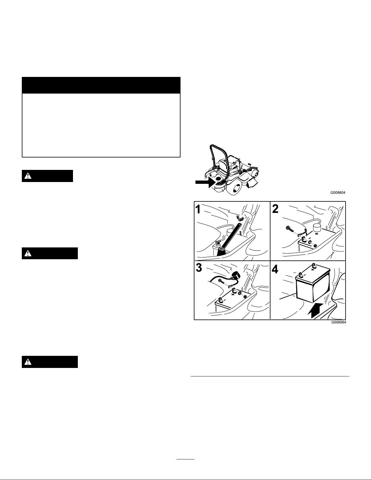
1.Disengagetheblade-controlswitch(PTO),movethe
motion-controlleverstotheneutral-lockedposition,
andsettheparkingbrake.
2.Stoptheengine,removethekey ,andwaitforallmoving
partstostopbeforeleavingtheoperatingposition.
3.Disconnectthenegativebatterycable(black)fromthe
negative(-)batteryterminal(Figure46).
WARNING
CALIFORNIA
Proposition65Warning
Batteryposts,terminals,andrelated
accessoriescontainleadandleadcompounds,
chemicalsknowntotheStateofCalifornia
tocausecancerandreproductiveharm.
W ash hands after handling .
DANGER
Batteryelectrolytecontainssulfuricacidwhichisa
deadlypoisonandcausessevereburns.
Donotdrinkelectrolyteandavoidcontactwith
skin,eyes,orclothing.Wearsafetyglassestoshield
youreyesandrubberglovestoprotectyourhands.
RemovingtheBattery
WARNING
4.Slidetheredterminalbootoffthepositive(red)battery
terminal,andremovethepositive(+)batterycable
Figure46).
(
5.Removethewingnutsecuringthebatteryclamp
(Figure46).
6.Removetheclamp(Figure46).
7.Removethebattery.
Batteryterminalsormetaltoolscouldshortagainst
metalmachinecomponentscausingsparks.Sparks
cancausethebatterygassestoexplode,resulting
inpersonalinjury.
•Whenremovingorinstallingthebattery,donot
allowthebatteryterminalstotouchanymetal
partsofthemachine.
•Donotallowmetaltoolstoshortbetween
thebatteryterminalsandmetalpartsofthe
machine.
WARNING
Incorrectbatterycableroutingcoulddamagethe
machineandcablescausingsparks.Sparkscan
causethebatterygassestoexplode,resultingin
personalinjury.
•Alwaysdisconnectthenegative(black)battery
cablebeforedisconnectingthepositive(red)
cable.
•Alwaysreconnectthepositive(red)batterycable
beforeconnectingthenegative(black)cable.
1.Removethewingnutand
clamp
2.Removethenegative
batterycablebeforethe
positive
36
Figure46
3.Removethepositive
batterycable
4.Removethebattery
Page 37

InstallingtheBattery
G017436
1.Positionthebatteryinthetraywiththeterminalposts
oppositefromthehydraulictank(Figure46).
2.Installthepositive(red)batterycabletopositive(+)
batteryterminal.
3.Installthenegative(black)batterycableandground
wiretothenegative(-)batteryterminal.
4.Securethecableswith2bolts,2washers,and2locknuts
Figure46).
(
5.Slidetheredterminalbootontothepositive(red)
batterypost.
6.Installtheclampandsecureitwiththewingnut(Figure
46).
ChargingtheBattery
WARNING
Chargingthebatteryproducesgassesthatcan
explode.
Neversmokenearthebatteryandkeepsparksand
amesawayfrombattery.
Important:Alwayskeepthebatteryfullycharged
(1.265specicgravity).Thisisespeciallyimportantto
preventbatterydamagewhenthetemperatureisbelow
0°C(32°F).
1.Chargebatteryfor10to15minutesat25to30amps
or30minutesat10amps.
2.Whenthebatteryisfullycharged,unplugthecharger
fromtheelectricaloutlet,thendisconnectthecharger
leadsfromthebatteryposts(Figure47).
3.Installthebatteryinthemachineandconnectthe
batterycables;refertoInstallingtheBattery(page37).
Figure47
1.Positivebatterypost
2.Negativebatterypost
3.Red(+)chargerlead
4.Black(-)chargerlead
ServicingtheFuses
Theelectricalsystemisprotectedbyfuses.Itrequires
nomaintenance,however,ifafuseblowscheckthe
component/circuitforamalfunctionorshort.
1.Thefusesarelocatedonrighthandconsolenextto
theseat(Figure48).
2.Toreplacethefuses,pulloutonthefusetoremoveit.
3.Installanewfuse(Figure48).
Note:Donotrunthemachinewiththebattery
disconnected,electricaldamagemayoccur.
1.Optional
accesory—15amp
2.Charge—25amp5.Console
3.PTO—10amp
37
Figure48
4.Main—25amp
Page 38
DriveSystem
Maintenance
CheckingtheSeatBelt
ServiceInterval:Beforeeachuseordaily
Visuallyinspecttheseatbeltforwear,cuts,andproper
operationofretractorandbuckle.Replaceitbeforeoperating
ifitisdamaged.
Checkingthe Rollover-Protection-System (ROPS)Knobs
ServiceInterval:Beforeeachuseordaily
WARNING
Toavoidinjuryordeathfromrollover:keeptheroll
barinthefullyraisedlockedpositionandusethe
seatbelt.
Ensuretheseatissecuredtothemachine.
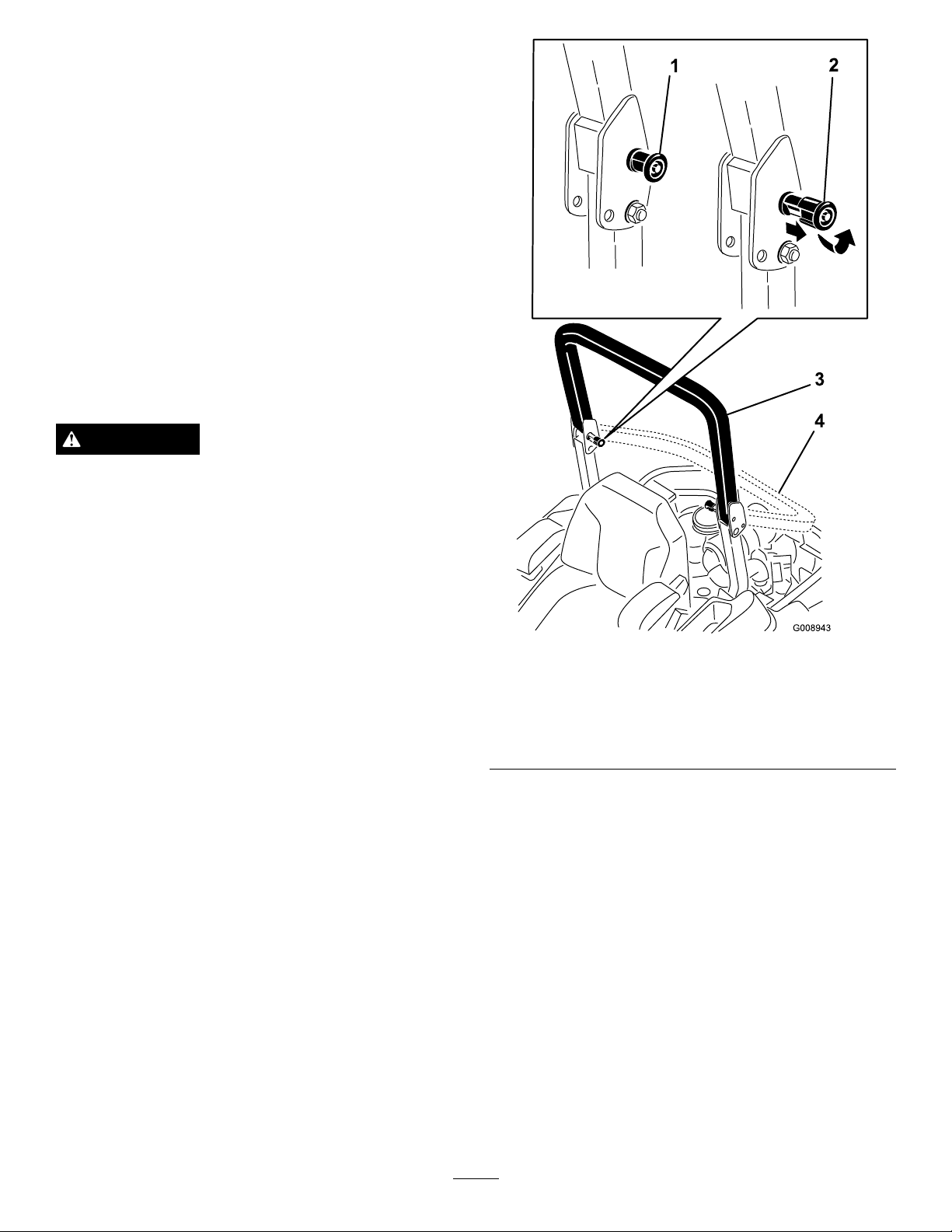
Checkthatboththemountinghardwareandtheknobsarein
goodworkingcondition.Makesurethattheknobsarefully
engagedwiththeROPSintheraisedposition.Theupper
hoopoftherollbarmayneedtobepushedforwardorpulled
rearwardtogetbothknobsfullyengaged(Figure49).
Figure49
1.ROPSknob(locked
position)
2.PulltheROPSknobout,
androtateit90degreesto
changetherollbarposition
3.Rollbarintheupright
position
4.Rollbarinthefolded
position
AdjustingtheTracking
1.Disengagetheblade-controlswitch(PTO).
2.Drivetoanopen,atarea,andmovethe
motion-controlleverstotheneutral-lockedposition.
3.MovethethrottlemidwaybetweenFastandSlow.
4.Movebothmotion-controlleversforwarduntilthey
bothhitthestopsintheT-slot.
5.Checkwhichwaythemachinetracks.
6.Ifittrackstotheright,loosentheboltsandadjust
theleftstopplaterearwardontheleftT-slotuntilthe
machinetracksstraight(Figure50).
7.Ifittrackstotheleft,loosentheboltsandadjustthe
rightstopplaterearwardontherightT-slotuntilthe
machinetracksstraight(Figure50).
8.Tightenthestopplate(Figure50).
38
Page 39

Figure50
Leftcontrollevershown
1.Controllever3.Stopplate
2.Bolt
CheckingtheWheelLugNuts
ServiceInterval:Aftertherst8hours
Yearly
Checkandtorquethewheellugnutsto122to136N-m(90
to100ft-lb).
AdjustingtheCaster-pivot Bearing
ServiceInterval:Every500hours/Yearly(whichevercomes
rst)
1.Disengagetheblade-controlswitch(PTO),movethe
motion-controlleverstotheneutral-lockedposition,
andsettheparkingbrake.
2.Stoptheengine,removethekey ,andwaitforallmoving
partstostopbeforeleavingtheoperatingposition.
3.Removethedustcapfromcasterandtightenthelock
Figure52).
nut(
4.Tightenthelocknutuntilthespringwashersareat,
andthenbackoffa1/4turntoproperlysetthepreload
onthebearings(Figure52).
Important:Makesurethatthespringwashersare
installedcorrectlyasshowninFigure52.
5.Installthedustcap(Figure52).
CheckingtheTirePressure
ServiceInterval:Every50hours/Monthly(whichever
comesrst)
Maintaintheairpressureinthereartiresat90kPa(13psi).
Uneventirepressurecancauseunevencut.Checkthetires
whentheyarecoldtogetthemostaccuratepressurereading.
Note:Thefronttiresaresemi-pneumatictiresanddonot
requireairpressuremaintenance.
Figure51
1.Springwashers
2.Locknut
Figure52
3.Dustcap
39
Page 40
AdjustingtheElectricClutch
CoolingSystem
ServiceInterval:Every500hours—Checktheelectric
clutch.
Theclutchisadjustabletoensureproperengagementand
properbraking.
1.Inserta0.38to0.53mm(0.015–0.02inch)feelergauge
throughoneinspectionslotinthesideoftheassembly.
Note:Makesureitisbetweenthearmatureandthe
rotor-frictionsurfaces.
Note:Thegapneedstobeatleast0.38mm(0.015
inch),andnotmorethan0.53mm(0.02inch).
2.Ifadjustmentisneeded,thensetat0.38mm(0.015
inch)foreachofthethreeadjustmentslotpositions.
3.Tightenthelocknutsuntilthereisaslightbindingon
thefeelergauge,butitcanbemovedeasilywithinthe
airgap(
4.Repeatthisfortheremainingslots.
5.Checkeachslotagainandmakeslightadjustmentsuntil
thefeelergaugebetweentherotorandarmaturewith
veryslightcontactbetweenthem.
Figure53).
Maintenance
CleaningtheEngineScreen
ServiceInterval:Beforeeachuseordaily
Beforeeachuseremoveanybuild-upofgrass,dirtor
otherdebrisfromtheenginescreen.Thiswillhelpinsure
adequatecoolingandcorrectenginespeedandwillreduce
thepossibilityofoverheatingandmechanicaldamagetothe
engine(Figure54).
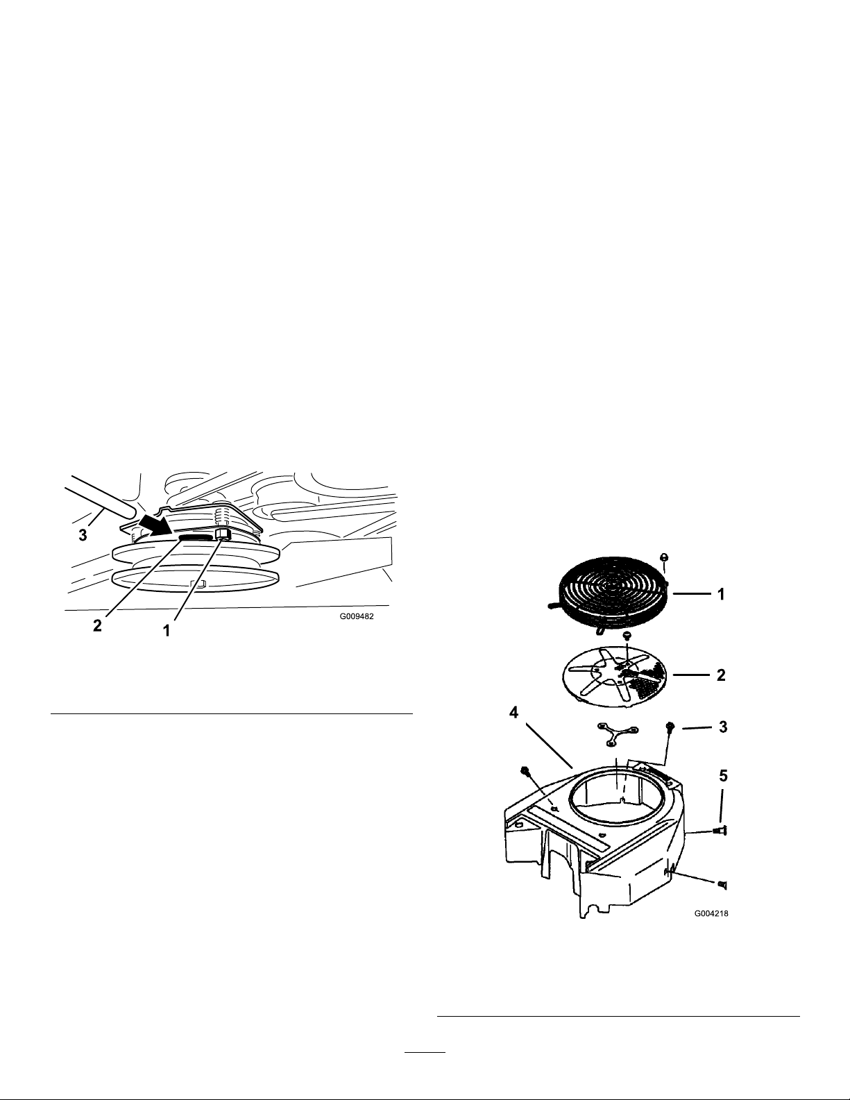
CleaningtheEngineCooling FinsandShrouds
ServiceInterval:Every100hours/Yearly(whichevercomes
rst)
1.DisengagethePTOandsettheparkingbrake.
2.Stoptheengine,removethekey ,andwaitforallmoving
partstostopbeforeleavingtheoperatingposition.
3.Removetheairintakescreen,recoilstarterandfan
housing(Figure54).
4.Cleanthedebrisandgrassfromtheengineparts.
5.Installairintakescreen,recoilstarterandfanhousing
Figure54).
(
Figure53
1.Adjustingnut3.Feelergauge
2.Slot
Figure54
1.Engineguard4.Fanhousing
2.Engineairintakescreen
3.Bolt
5.Screw
40
Page 41

BeltMaintenance
G009036
1
2
g017627
InspectingtheBelts
ServiceInterval:Every50hours
Checkthebeltsforsquealingwhenthebeltisrotating,blades
slippingwhencuttinggrass,frayedbeltedges,burnmarks,
andcracksaresignsofawornmowerbelt.Replacethe
mowerbeltifanyoftheseconditionsareevident.
ReplacingtheMowerBelt
Squealingwhenthebeltisrotating,bladesslippingwhen
cuttinggrass,frayedbeltedges,burnmarks,andcracksare
signsofawornmowerbelt.Replacethemowerbeltifanyof
theseconditionsareevident.
1.DisengagethePTO,movethemotion-controlleversto
theneutral-lockedposition,andsettheparkingbrake.
2.Stoptheengine,removethekey ,andwaitforallmoving
partstostopbeforeleavingtheoperatingposition.
3.Lowerthemowertothe76mm(3inches)height-of-cut.
4.Removethebeltcovers(Figure55).
Figure55
1.Pushthetabdown2.Removethebeltcover
5.Usearatchetinthesquareholeintheidlerarmto
removetensionontheidlerspring(Figure56).
6.Removethebeltfromthemower-deckpulleys.
7.Removethebeltguideonthespring-loadedidlerarm
(Figure56).
8.Removetheexistingbelt.
9.Installthenewbeltaroundthemowerpulleysandthe
clutchpulleyundertheengine(Figure56).
Figure56
1.Clutchpulley5.Squareholeintheidler
2.Mowerbelt
3.Spring-loadedidlerpulley
4.Ratchet
10.Installthebeltguideontheidlerarm(Figure56).
11.Usingtheratchetinthesquarehole,installtheidler
spring(Figure56).
Note:Makesurethespringendsareseatedinthe
anchorgrooves.
12.Installthebeltcovers(Figure57).
armfortheratchet
6.Idler-greasetting
7.Beltguide
41
Page 42
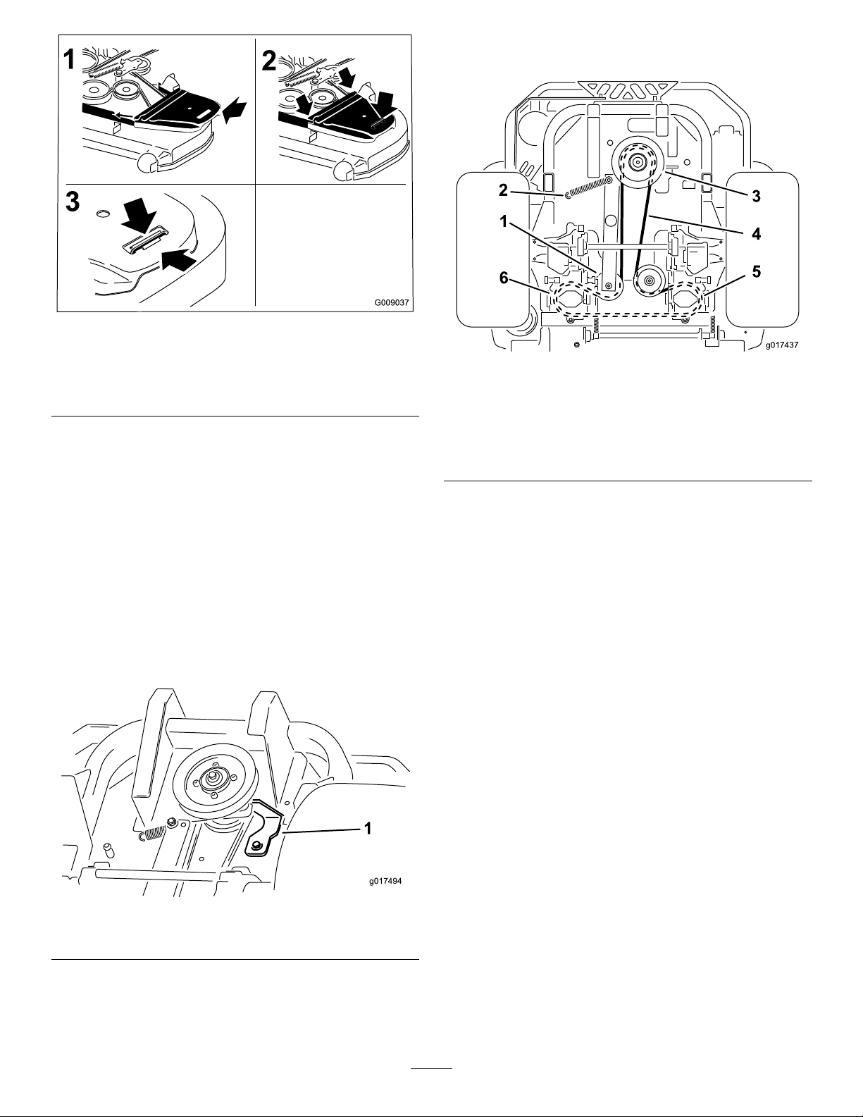
Figure57
g017494
1
g017437
1
6
2
3
4
5
8.Installthenewbeltaroundtheenginepulleyandthe
2drivepulleys.
1.Positionthebeltcover3.Ensurethatthetabis
2.Slidethebeltcoverunder
thesidecatches
underthemetalcatch
ReplacingtheHydraulic Pump-driveBelt
1.DisengagethePTOandsettheparkingbrake.
2.Stoptheengine,removethekey ,andwaitforallmoving
partstostopbeforeleavingtheoperatingposition.
3.Removethemowerbelt;referto
Belt(page41).
4.Raisethemachineandsupportitwithjackstands
(Figure59).
5.Removetheclutchstop(Figure58).
ReplacingtheMower
Figure59
1.Idlerpulley4.Pump-drivebelt
2.Idler-springpost5.Righthand
3.Enginepulley
hydraulic-pumppulley
6.Lefthandhydraulic-pump
pulley
9.Installtheclutchstop(Figure58).
10.Installthemowerbelt;refertoReplacingtheMower
Belt(page41).
Figure58
1.Clutchstop
6.Removetheidlerspringfromthepost(Figure59).
7.Removetheexistingbeltfromthehydraulicunitdrive
pulleysandtheenginepulley
42
Page 43

ControlsSystem
Maintenance
AdjustingtheControl-handle Position
Thereare2heightpositionsforthecontrollevers—highand
low .Removetheboltstoadjusttheheightfortheoperator.
1.DisengagethePTO,movethemotion-controlleversto
theneutral-lockedposition,andsettheparkingbrake.
2.Stoptheengine,removethekey ,andwaitforallmoving
partstostopbeforeleavingtheoperatingposition.
3.Loosentheboltsandangenutsinstalledinthelevers
(Figure60).
4.Aligntheleversinthefront-to-rearpositionby
bringingtheleverstogethertotheneutralposition,and
slidethemuntiltheyarealigned,thentightenthebolts
(Figure61).
Figure60
1.Bolt
2.Handle4.Nut
3.Controllever
Figure61
5.Iftheendsofthelevershitagainsteachother,refer
toAdjustingtheMotionControlNeutral-lockPivot
(page45).
6.Repeattoadjustthecontrollevers.
AdjustingtheMotion-control Linkage
Locatedoneithersideofthefueltank,belowtheseatarethe
pump-controllinkages.Rotatingthepumplinkagewitha
1/2inchwrenchallowsne-tuningadjustments,sothatthe
machinedoesnotmoveinneutral.Anyadjustmentsshould
bemadeforneutralpositioningonly .
WARNING
Theenginemustberunningandthedrivewheels
mustbeturning,sothemotion-controladjustment
canbeperformed.Contactwithmovingpartsor
hotsurfacesmaycausepersonalinjury.
Keepyourngers,hands,andclothingclearof
rotatingcomponentsandhotsurfaces.
1.Priortostartingtheengine,pushthedeck-liftpedal,
removetheheight-of-cutpin,andlowerthedeckto
theground.
2.Raisetherearofmachineupandsupportwithjack
stands(orequivalentsupport)justhighenoughto
allowthedrivewheelstoturnfreely .
3.Movetheseattothefurthestrearpositiontoexpose
thefrontnuts.
4.Loosenthefrontnuts.
Note:Thenutsdonotneedtoberemoved.
43
Page 44

5.Movetheseattothefurthestforwardpositionto
g018378
1
2
g018380
1
2
g017438
1 1
exposetherearnuts.
11.Removetheelectricalconnectionfromtheseatsafety
switch,locatedunderthebottomcushionoftheseat.
6.Loosentherearnuts.
Note:Thenutsdonotneedtoberemoved.
7.Slidetheseatandseatplateforwardtoallowthefront
nutstogothroughthekeyhole(Figure62).
Figure62
1.Seat
2.Frontnutswithkeyhole
8.Removetheseatandseatplatefromthemachine.
9.Unplugtheharnessconnectorfromtheseatswitch
locatedundertheseat(Figure63).
Note:Theswitchisapartoftheseatassembly.
12.Temporarilyinstallajumperwireacrosstheterminals
intheconnectorofthemainwiringharness.
13.Starttheengine,runtheengineatfullthrottle,and
releasethebrake.
Important:Thebrakemustbeengaged,and
themotion-controlleversmustbeouttostartthe
engine.Theoperatordoesnothavetobeinthe
seatbecauseofthejumperwirebeingused.
14.Runtheunitatleast5minuteswiththedrivelevers
atfullforwardspeedtobringthehydraulicoilupto
operatingtemperature.
Note:Themotion-controlleverneedstobeinneutral
whilemakinganynecessaryadjustments.
15.Bringthemotion-controlleversintotheneutral
position.
16.Adjustthepump-controlrodsbylooseningthe2jam
nutsandrotatingtheadjustmentnutintheappropriate
directionuntilthewheelsslightlycreepinreverse
Figure64).
(
17.Movethemotion-controlleverstothereverseposition,
andwhileapplyingslightpressuretothelever,allow
thereverse-indicatorspringstobringtheleversback
toneutral.
Note:Thewheelsmuststopturningorslightlycreep
inreverse.
18.Tightenthe2jamnutsagainsttheadjustmentnut
Figure64).
(
Figure63
1.Harnessconnector
1.Jamnut2.Adjustmentnut
Figure64
19.Shutoffthemachine
10.Loosentheboltsholdingtheseattothemachine,and
slidetheseatforwardintheslotstoremovetheseat.
20.Removethejumperwirefromthewireharness,and
plugtheconnectorintotheseatswitch.
44
Page 45

21.Installtheseat.
22.Removethejackstands.
23.Raisethedeckandinstalltheheight-of-cutpin.
24.Ensurethatthemachinedoesnotcreepinneutralwith
theparkingbrakesdisengaged.
AdjustingtheMotion-control
AdjustingtheMotionControl Neutral-lockPivot
Theangednutcanbeadjustedtoobtainamoredesired
motion-controlleverresistancewhenmovingittothe
neutral-lockposition.SeeFigure66foradjustmentoptions.
1.Loosenthejamnut.
2.Tightenorloosentheangednuttothedesiredfeel.
Damper
Thetopdamper-mountingboltcanbeadjustedtoobtaina
moredesiredmotion-controlleverresistance.SeeFigure65
formountingoptions.
Figure65
RHMotionControlShown
1.T orquethelocknutto23N-m(17ft-lb).Theboltmust
protrudepasttheendofthelocknutaftertorquing.
2.Mostresistance(rmestfeel)
3.Damper
4.Mediumresistance(mediumfeel)
5.Leastresistance(softestfeel)
Note:Formoreresistance,tightentheangednut.
Note:Forlessresistance,loosentheangednut
3.Tightenthejamnut.
Figure66
1.Flangednut2.Jamnut
45
Page 46
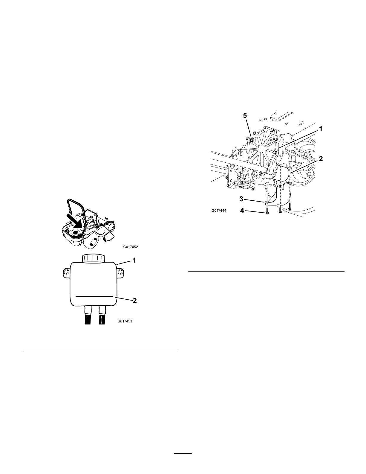
HydraulicSystem
G017452
G017451
1
2
G017444
1
2
3
4
5
Maintenance
properlyperformthisprocedurecanresultinirreparable
damagetothetransaxledrivesystem.
RemovingHydraulic-systemFilters
ServicingtheHydraulic System
HydraulicOilType:Toro
or20W-50engineoil.
Important:Useoilspecied.Otheruidscouldcause
systemdamage.
HydraulicSystemCapacity(withltersremoved):4.45
L(150oz)
®
HYPR-OIL
CheckingtheHydraulic-oilLevel
ServiceInterval:Every25hours
1.Allowthehydraulicoiltocooldown,andchecktheoil
levelwhentheoiliscold.
2.Checktheexpansionreservoir,and,ifnecessary,add
®
Toro
HYPR-OIL
COLDline.
™
500hydraulicoiltotheFULL
™
500hydraulicoil
1.Stoptheengine,waitforallmovingpartstostop,allow
theenginetocool,removethekey,andengagethe
parkingbrake.
2.Locatethelterandguardsoneachtransaxle-drive
system(Figure68).
3.Removethreescrewssecuringthelterguardand
guard(
Figure68).
Figure68
Rightsideshown
Figure67
1.Expansionreservoir
Changingthe
Hydraulic-systemFilter
2.FULLCOLDline
andOil
Thelterandoilarechangedatthesametime.Donotuse
theoilagain.Oncethenewlterisinstalled,andtheoilis
added,anyairinthesystemmustbepurged.
Thebleedingprocessisrepeateduntiltheoilremainsatthe
FULLCOLDlineinthereservoirafterpurging.Failureto
1.Transaxledrive
2.Oillter
3.Filterguard
4.Carefullycleantheareaaroundthelters.
Important:Donotallowdirttoenterthe
hydraulicsystem,orcontaminationmayoccur.
5.Placeadrainpanbelowtheltertocatchtheoilthat
drainswhenthelterandventplugsareremoved.
6.Locateandremovetheventplugoneachtransmission
7.Unscrewtheltertoremoveit,andallowtheoilto
drainfromdrivesystem.
8.Repeatthisprocedureforbothlters.
4.Screws
5.Ventplug
InstallingtheHydraulic-systemFilters
ServiceInterval:Aftertherst50hours
Every400hours
1.Applyathincoatofoilonthesurfaceoftherubber
sealofeachlter.
2.Turnthelterclockwiseuntiltherubbersealcontacts
thelteradapter,thentightenthelteranadditional
3/4to1fullturn.
46
Page 47
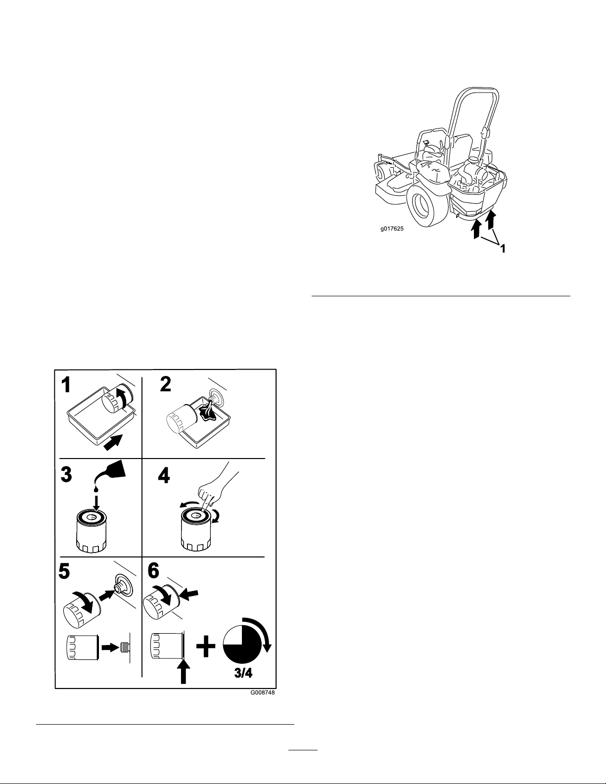
3.Repeatfortheotherlter.
G008748
3/4
1
2
3
4
5
6
g017625
1
4.Installthelterguardsovereachlteraspreviously
removed.
5.Usethe3screwstosecurethelterguards.
6.Verifythattheventplugsareremovedbeforeadding
theoil.
7.Slowlypourthespeciedoilthroughtheexpansion
reservoiruntiloilcomesoutofoneofthevent-plug
holes.
8.Stopandinstallthatventplug.
9.Torquetheplugto20N-m(15ft-lb).
10.Continuetoaddoilthroughtheexpansionreservoir
untiloilcomesoutoftheremainingvent-plugholeon
thesecondtransmission.
11.Stopandinstallthatventplug.
12.Torquetheplugto20N-m(15ft-lb).
13.Continuetoaddoilthroughtheexpansionreservoir
untilitreachestheFULLCOLDlineontheexpansion
reservoir.
14.Proceedto
Important:Failuretoperformthe
the Hy draulic System
hydraulicltersandoilcanresultinirreparable
damagetothetransaxledrivesystem.
BleedingtheHydraulicSystem(page47).
Bleeding
procedureafterchanging
BleedingtheHydraulicSystem
1.Raisetherearofmachineup,andsupportitwithjack
stands(orequivalentsupport)justhighenoughto
allowdrivewheelstoturnfreely.
Figure70
1.Jackingpoints
2.Entertheoperator'sposition,starttheengine,move
thethrottlecontrolaheadtothe1/2throttleposition,
anddisengageparkingbrake.
A.Movethebypassleversintothepushingthe
machineposition.Withthebypassvalves
openandtheenginerunning,slowlymovethe
motion-controlleversinbothforwardandreverse
(5or6times).
B.Movethebypassleversintotheoperating
themachineposition.Withthebypassvalve
closedandtheenginerunning,slowlymovethe
directionalcontrolinbothforwardandreverse
directions(5to6times).
C.Stoptheengineandchecktheoillevelinthe
expansionreservoir.Addthespeciedoilasuntil
itreachestheFULLCOLDlineontheexpansion
reservoir.
3.Repeatstep2untilalltheairiscompletelypurgedfrom
thesystem.
Note:Whenthetransaxleoperatesatnormalnoise
levels,movessmoothlyforward,andreversesatnormal
speeds,thenthetransaxleisconsideredpurged.
4.Checktheoillevelintheexpansionreservoironelast
time.AddthespeciedoilasuntilitreachestheFULL
COLDlineontheexpansionreservoirifnecessary.
Figure69
47
Page 48
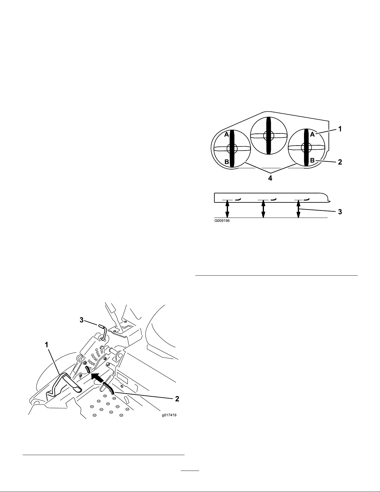
MowerDeck
g017419
2
1
3
6.Inserttheheightadjustmentpinintothe7.6cm(3
inches)cuttingheightlocation.
Maintenance
LevelingtheMowerDeck
SettingUptheMachine
Note:Ensurethatthemowerdeckisleveledbefore
matchingtheheight-of-cut(HOC).
1.Positionthemoweronaatsurface.
2.Disengagetheblade-controlswitch(PTO),movethe
motion-controlleverstotheneutral-lockedposition,
andsettheparkingbrake.
3.Stoptheengine,removethekey ,andwaitforallmoving
partstostopbeforeleavingtheoperatingposition.
4.Checktirepressureofthedrivetires.
5.Ifneeded,adjustto90kPa(13psi).
6.Positionthemowertothe76mm(3inches)
height-of-cutposition.
DeckLeveling
1.Positionthemoweronaatsurface.
2.Stopengine,waitforallmovingpartstostop,remove
thekey ,andengagetheparkingbrake.
3.Checkthetirepressureinthedrivetires.
Note:Properinationpressureforthetiresis90kPa
(13psi).
4.Positionthetransportlockinthelatchingposition.
5.Pushthedeck-liftpedalallthewayforwardandthe
deckwilllatchatthe14cm(5-1/2inches)transport
position(
Figure71).
7.Releasethetransportlockandallowthedecktolower
tothecuttingheight.
8.Raisethedischargechute.
9.Onbothsidesofthedeck,measurefromthelevel
surfacetothefronttipoftheblade(PostionA)as
showninFigure72.
Note:Themeasurementshouldread7.6mm(3
inches)
Figure72
1.7.6cm(3inches)at
positionAiscorrect
2.8.3cm(3-1/4inches)at
positionBiscorrect
10.Ifneeded,loosenthewhizlocknutonthesideofthe
yokeandthejamnutontop(
11.Finetunethescrewadjusterbyturningittoget7.6
mm(3inches)height.
3.Measureherefromthe
bladetiptothehard
surface
4.MeasureatpositionAand
Bonbothsides
Figure73).
1.Deck-liftpedal
2.Height-of-cutpin
Note:T oincreasetheheight,turntheadjusterscrew
clockwise;todecrease,turnitcounterclockwise.
Note:Ifthefrontdecklinksdonothaveenough
adjustmenttoachieveaccuratecutheight,the
singlepointadjustmentcanbeutilizedtogainmore
adjustment.
Figure71
3.Transportlock
48
Page 49
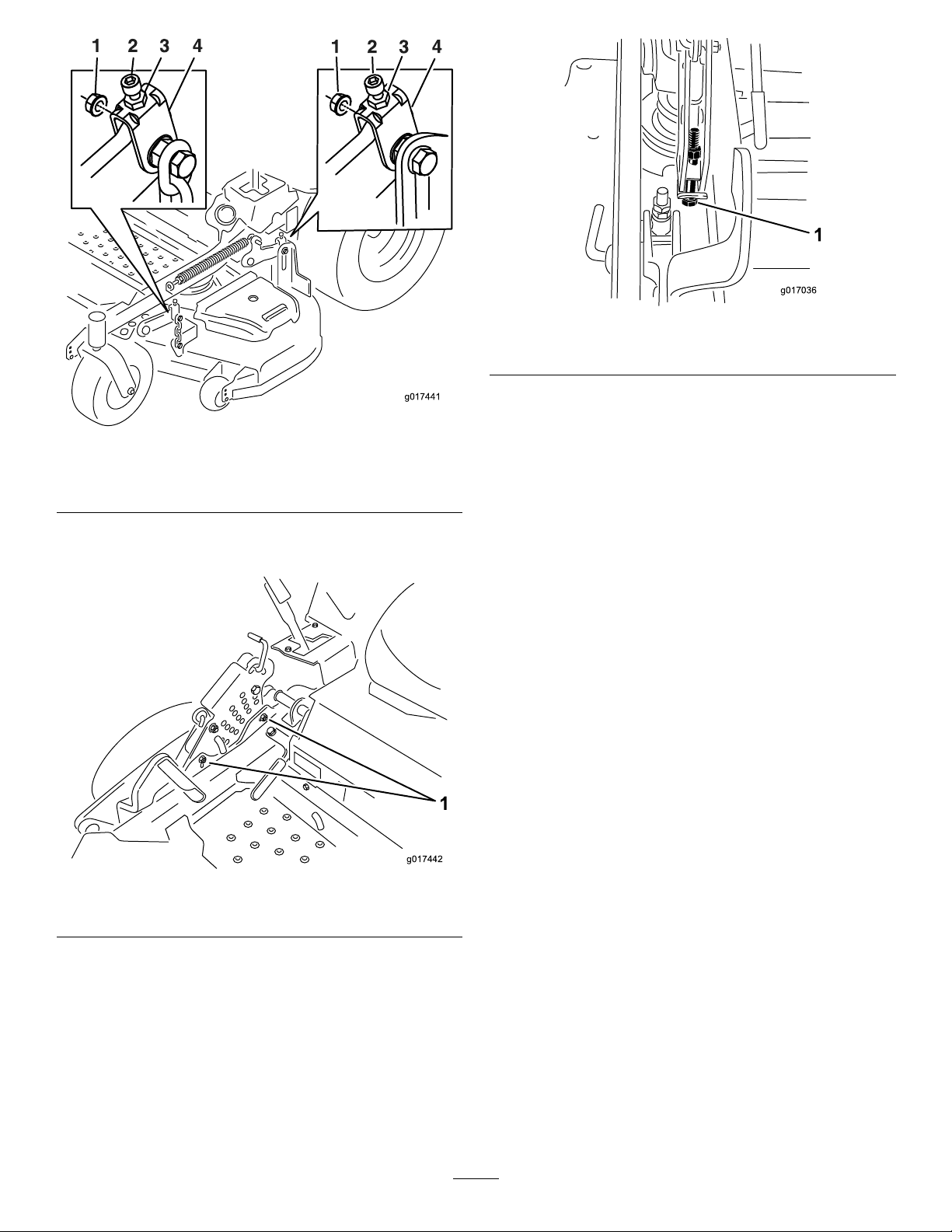
g017441
Figure73
g017442
1
g017036
1.Whizlocknut3.Jamnut
2.Adjusterscrew4.Y oke
Figure75
1.Single-pointadjustmentbolt
14.Tightenthe2boltsatthebottomoftheheight-of-cut
plate(Figure74).T
Note:Inmostconditions,thebackbladetipshould
beadjusted6.4mm(1/4inch)higherthanthefront.
15.Torquethe2boltsto37to45N-m(27to33ft-lb).
12.Toadjustthesinglepointsystem,loosenthe2boltsat
thebottomoftheheight-of-cutplate(Figure74).
Figure74
1.Boltsatthebottomoftheheight-of-cutplate
13.Ifthedeckistoolow ,tightenthesinglepoint
adjustmentboltbyrotatingitclockwise.Ifthedeckis
toohigh,loosenthesinglepointadjustmentboltby
rotatingitcounterclockwise(
Figure75).
16.Onbothsidesofthedeck,measurefromthelevel
surfacetothebacktipoftheblade(postionB)as
showninFigure72.
Note:Themeasurementshouldread8.3cm(3-1/4
inches)
17.Finetunethescrewadjusterbyturningittoget8.3
mm(3-1/4inches)height(Figure73).
Toincreasetheheight,turntheadjustmentnut
clockwise;todecrease,turncounterclockwise.
18.Measureuntilall4sidesarethecorrectheight.
19.Tightenallofthenutsonthedeck-lift-armassemblies.
20.Lowerthedischargechute.
Note:Loosenortightenthesingle-pointadjustment
boltenoughtomovetheheight-of-cutplatemounting
boltsatleast1/3thelengthoftheavailabletravel
intheirslots.Thiswillregainsomeupanddown
adjustmentoneachofthe4decklinks.
49
Page 50
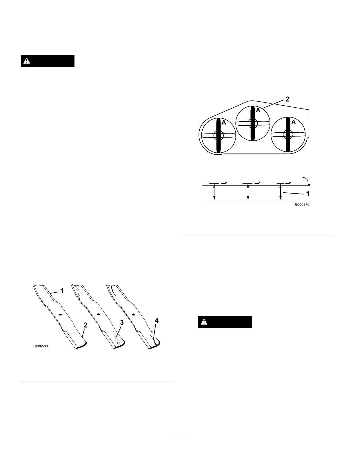
ServicingtheCuttingBlades
Toensureasuperiorqualityofcut,keepthebladessharp.
Forconvenientsharpeningandreplacement,youmaywant
tokeepextrabladesonhand.
WARNING
Awornordamagedbladecanbreak,andapiece
ofthebladecouldbethrownintotheoperator's
orbystanders’area,resultinginseriouspersonal
injuryordeath.
•Inspectthebladesperiodicallyforwearor
damage.
•Replaceawornordamagedblade.
BeforeInspectingorServicingthe
Blades
Parkthemachineonalevelsurface,disengagethebladesand
settheparkingbrake.Turntheignitionkeytooff.Remove
thekey ,anddisconnectthesparkplugwiresfromthespark
plugs.
CheckingforBentBlades
1.DisengagethePTO,movethemotion-controlleversto
theneutral-lockedposition,andsettheparkingbrake.
2.Stoptheengine,removethekey ,andwaitforallmoving
partstostopbeforeleavingtheoperatingposition.
3.Rotatethebladesuntiltheendsfaceforwardand
backward.
4.Measurefromalevelsurfacetothecuttingedge,
positionA,oftheblades(Figure77).
InspectingtheBlades
ServiceInterval:Beforeeachuseordaily
1.Inspectthecuttingedges(Figure76).
2.Iftheedgesarenotsharporhavenicks,removeand
sharpentheblade;refertoSharpeningtheBlades(page
51).
3.Inspecttheblades,especiallyinthecurvedarea.
4.Ifyounoticeanycracks,wear,oraslotforminginthis
area,immediatelyinstallanewblade(Figure76).
Figure76
1.Cuttingedge3.Wear/slotforming
2.Curvedarea4.Crack
Figure77
1.Measureherefromblade
tohardsurface
5.Rotatetheoppositeendsofthebladesforward.
6.Measurefromalevelsurfacetothecuttingedgeofthe
bladesatthesamepositionasinstep
Note:Thedifferencebetweenthedimensions
obtainedinsteps4and5mustnotexceed3mm
(1/8inch).
Note:Ifthisdimensionexceeds3mm(1/8inch),the
bladeisbentandmustbereplaced.
2.PositionA
4above.
WARNING
Abladethatisbentordamagedcouldbreak
apartandcouldseriouslyinjureorkillyouor
bystanders.
•Alwaysreplacebentordamagedblade
withanewblade.
•Donotleorcreatesharpnotchesinthe
edgesorsurfacesoftheblade.
50
Page 51

RemovingtheBlades
Bladesmustbereplacedifasolidobjectishit,ifthe
bladeisoutofbalance,orifthebladeisbent.Toensure
optimumperformanceandcontinuedsafetyconformance
ofthemachine,usegenuineT ororeplacementblades.
Replacementbladesmadebyothermanufacturersmayresult
innonconformancewithsafetystandards.
1.Holdthebladeendusingaragorathickly-padded
glove.
Note:Ifthebladestaysinahorizontalposition,the
bladeisbalancedandcanbeused.
Figure80
1.Blade2.Balancer
2.Removethebladebolt,thecurvedwasher,andthe
bladefromthespindleshaft(Figure78).
Figure78
1.Sailareaoftheblade3.Curvedwasher
2.Blade4.Bladebolt
3.Ifthebladeisnotbalanced,lesomemetalofftheend
ofthesailareaonly(Figure78).
4.Repeatthisprocedureuntilthebladeisbalanced.
InstallingtheBlades
1.Installthebladeontothespindleshaft(Figure81).
Important:Thecurvedpartoftheblademustbe
pointingupwardtowardtheinsideofthemowerto
ensurepropercutting.
2.Installthespringdiskandbladebolt(Figure81).
Note:Thespring-diskconemustbeinstalledtoward
thebolthead(Figure81).
3.Torquethebladeboltto115to150N-m(85to
110ft-lb).
SharpeningtheBlades
1.Usealetosharpenthecuttingedgeatbothendsof
theblade(Figure79).
Note:Maintaintheoriginalangle.
Note:Thebladeretainsbalanceifthesameamount
ofmaterialisremovedfrombothcuttingedges.
Figure79
1.Sharpenattheoriginalangle
2.Checkthebalanceofthebladebyputtingitonablade
balancer(Figure80).
Figure81
1.Sailareaoftheblade3.Springdisk
2.Blade4.Bladebolt
51
Page 52
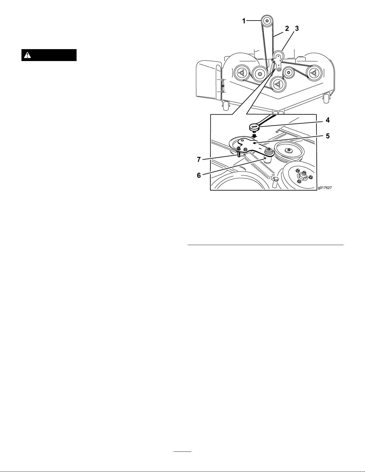
RemovingtheMowerDeck
g017627
Beforeservicingorremovingthemowerdeck,the
spring-loadeddeckarmsmustbelockedout.
WARNING
Deck-lift-armassemblieshavestoredenergy.
Removingthedeckwithoutreleasingthestored
energycancauseseriousinjuryordeath.
Donotattempttodisassemblethedeckfromthe
frontframewithoutlockingoutthestoredenergy.
1.Stoptheengine,waitforallmovingpartstostop,
removethekey ,andengagetheparkingbrake.
2.Removetheheight-adjustmentpinandlowerthedeck
totheground.
3.Placetheheight-adjustmentpininthe7.6cm(3inches)
cutting-heightlocation.
Note:Thislocksthedeck-liftarmsinthelowest
positionwhenthedeckisremovedandthestored
energyinthedeckspringisreleased.
4.Removethebeltcovers.
5.Liftuptheoorpanandinsertaratchetintothesquare
holeinthedeckidler(
6.Rotatethedeckidlerclockwiseandremovethemower
belt(Figure82).
Figure82).
Figure82
1.Clutchpulley5.Squareholeintheidler
2.Mowerbelt
3.Spring-loadedidlerpulley
4.Ratchet
armfortheratchet
6.Idlergreasetting
7.Beltguide
7.Removeandretainthehardwareonbothsidesofthe
deck(Figure83).
52
Page 53

g017417
2
Figure83
g015594
1
6 2
4
7
3
5
1.Removethereardeckliftattachmentshoulderboltandnut.
2.Removethefrontdeckliftattachmentshoulderboltandnut.
ReplacingtheGrassDeector
WARNING
Anuncovereddischargeopeningcouldallowthe
lawnmowertothrowobjectsintheoperator'sor
bystander'sdirectionandresultinseriousinjury.
Also,contactwiththebladecouldoccur.
Donotoperatethelawnmowerunlessyouinstalla
coverplate,amulchplate,grassdeectororbagger.
1.Removethelocknut,thebolt,thespring,andthespacer
holdingthedeectortothepivotbrackets(Figure84).
2.Removethedamagedorworngrassdeector(Figure
84).
8.Slidethedeckouttotherightsideofthemachine.
Figure84
1.Bolt
2.Spacer6.GrassDeector
3.Locknut
4.Spring
5.Springinstalled
7.Jhookendofspring
3.Placethespacerandthespringontograssdeector.
4.PlaceoneJendofthespringbehindthedeckedge.
Note:MakesureoneJendofthespringisinstalled
behindthedeckedgebeforeinstallingtheboltas
showninFigure84.
5.Installtheboltandthenut.
6.PlaceoneJhookendofthespringaroundthegrass
deector(Figure84).
Important:Thegrassdeectormustbeable
torotate.Liftthedeectoruptothefullopen
positionandensurethatitrotatesintothefull
downposition.
53
Page 54

Cleaning
Storage
CleaningUndertheMower
ServiceInterval:Beforeeachuseordaily
1.Disengagetheblade-controlswitch(PTO),movethe
motion-controlleverstotheneutral-lockedposition,
andsettheparkingbrake.
2.Stoptheengine,removethekey ,andwaitforallmoving
partstostopbeforeleavingtheoperatingposition.
3.Raisethemowertothetransportposition.
DisposingofWaste
Engineoil,batteries,hydraulicoil,andenginecoolantare
pollutantstotheenvironment.Disposeoftheseaccordingto
yourstateandlocalregulations.
CleaningandStorage
1.Disengagethepowertakeoff(blade-controlswitch
(PTO),settheparkingbrake,andturntheignitionkey
toOff.Removethekey.
2.Removegrassclippings,dirt,andgrimefromthe
externalpartsoftheentiremachine,especiallythe
engineandhydraulicsystem.Cleandirtandchafffrom
theoutsideoftheengine-cylinder-headnsandblower
housing.
Important:Y oucanwashthemachinewithmild
detergentandwater.Donotpressurewashthe
machine.Avoidexcessiveuseofwater,especially
nearthecontrolpanel,engine,hydraulicpumps,
andmotors.
3.Checkthebrake.
4.Servicetheaircleaner;referto
Cleaner(page30)
5.Greasethemachine;referto
(page28)
6.Changethecrankcaseoil;referto
Oil(page32)
7.Checkthetirepressure;referto
Pressure(page39)
8.Changethehydrauliclters;referto
HydraulicSystem(page46)
9.Chargethebattery;referto
36)
10.Scrapeanyheavybuildupofgrassanddirtfromthe
undersideofthemower,thenwashthemowerwith
agardenhose.
.
.
.
.
.
ServicingtheAir
GreasingandLubrication
ChangingtheEngine
CheckingtheTire
Servicingthe
.
ServicingtheBattery(page
Note:Runthemachinewiththeblade-controlswitch
(PTO)engaged,andtheengineathighidlefor2to
5minutesafterwashing.
11.Checktheconditionoftheblades;referto
theCuttingBlades(page50).
12.Preparethemachineforstoragewhennon-useoccurs
over30days.Preparethemachineforstorageas
follows:
A.Addapetroleumbasedstabilizer/conditionerto
fuelinthetank.Followmixinginstructionsfrom
thestabilizermanufacturer.Donotuseanalcohol
basedstabilizer(ethanolormethanol).
Note:Afuelstabilizer/conditionerismost
effectivewhenmixedwithfreshfuelandusedat
alltimes.
B.Runtheenginetodistributeconditionedfuel
throughthefuelsystem(5minutes).
C.Stoptheengine,allowittocool,anddrainthefuel
tank;referto
54
ServicingtheFuelTank(page35).
Servicing
Page 55

D.Restarttheengineandrunituntilitstops.
E.Disposeoffuelproperly .Recycleasperlocal
codes.
Important:Donotstore
stabilizer/conditionedfuelover90days.
13.Checkandtightenallbolts,nuts,andscrews.Repairor
replaceanypartthatisdamaged.
14.Paintallscratchedorbaremetalsurfaces.Paintis
availablefromyourAuthorizedServiceDealer.
15.Storethemachineinaclean,drygarageorstoragearea.
Removethekeyfromtheignitionswitchandkeepit
outofreachofchildrenorotherunauthorizedusers.
Coverthemachinetoprotectitandkeepitclean.
55
Page 56

Troubleshooting
Problem
Thestarterdoesnotcrank.
Theenginedoesnotstart,startshard,or
failstokeeprunning.
PossibleCauseCorrectiveAction
1.Theblade-controlswitch(PTO)is
engaged.
2.Theparkingbrakeisnoton.
3.Themotion-controlleversarenotinthe
neutral-lockposition.
4.Theoperatorisnotseated.
5.Thebatteryisdead.
6.Theelectricalconnectionsarecorroded
orloose.
7.Thefuseisblown.7.Replacethefuse.
8.Therelayorswitchiswornordamaged.
1.Thefueltankisempty.1.Fillthefueltank.
2.Thefuel-shutoffvalveisclosed.2.Openthefuel-shutoffvalve.
3.Theoillevelinthecrankcaseislow.3.Addoiltothecrankcase.
4.Thethrottleisnotinthecorrectposition.4.Besurethatthethrottlecontrolis
5.Thereisdirtinthefuellter.5.Replacethefuellter.
6.Thereisdirt,water,orstalefuelisin
thefuelsystem.
7.Theaircleanerisdirty.
8.Theseatswitchisnotfunctioning
properly.
9.Theelectricalconnectionsare
corroded,loose,ordamaged.
10.Therelayorswitchiswornordamaged.
11.Thesparkplugisfouledorimproperly
gapped.
12.Thespark-plugwireisnotconnected.
1.Movetheblade-controlswitch(PTO)to
thedisengagedposition.
2.Settheparkingbrake.
3.Ensurethatthemotion-controllevers
areintheneutral-lockposition.
4.Sitontheseat.
5.Chargethebattery .
6.Checktheelectricalconnectionsfor
goodcontact.
8.ContactanAuthorizedServiceDealer.
midwaybetweentheslowandfast
positions.
6.ContactanAuthorizedServiceDealer.
7.Cleanorreplacetheair-cleaner
element.
8.Checktheseat-switchindicator.
Replacetheseatifnecessary.
9.Checktheelectricalconnections
forgoodcontact.Cleanthe
connectorterminalsthoroughly
withelectrical-contactcleaner,apply
dielectricgrease,andmakethe
appropriateconnections.
10.ContactanAuthorizedServiceDealer.
11.Adjustorreplacethesparkplug.
12.Checkthespark-plugwireconnection.
Theenginelosespower.
Theengineoverheats.
Themowerpullstotheleftorright(with
leversfullyforward)
1.Theengineloadisexcessive.1.Reducethegroundspeed.
2.Theaircleanerisdirty.
3.Theoillevelinthecrankcaseislow.3.Addoiltothecrankcase.
4.Thecoolingnsandtheairpassages
abovetheengineareplugged.
5.Theventholeinthefuelcapisplugged.5.Cleanorreplacethefuelcap.
6.Thereisdirtinthefuellter.6.Replacethefuellter.
7.Thereisdirt,water,orstalefuelisin
thefuelsystem.
1.Theengineloadisexcessive.1.Reducethegroundspeed.
2.Theoillevelinthecrankcaseislow.2.Addoiltothecrankcase.
3.Thecoolingnsandtheairpassages
abovetheengineareplugged.
1.Thetrackingneedsadjustment1.Adjustthetracking.
2.Thetirepressureinthedrivetiresis
notcorrect.
2.Cleantheair-cleanerelement.
4.Removetheobstructionfromthe
coolingnsandtheairpassages.
7.ContactanAuthorizedServiceDealer.
3.Removetheobstructionfromthe
coolingnsandtheairpassages.
2.Adjustthetirepressureinthedrive
tires.
56
Page 57

Problem
PossibleCauseCorrectiveAction
Themachinedoesnotdrive.
Themachinevibratesabnormally.
Themachineproducesanunevencutting
height.
1.Thebypassvalvesarenotclosedtight.1.Tightenthebypassvalves.
2.Thepumpbeltisworn,loose,or
broken.
3.Thepumpbeltisoffapulley .3.Changethebelt.
4.Theidlerspringisbrokenormissing.4.Replacethespring.
5.Thehydraulicoillevelislowortoohot.5.Addhydraulicoiltothereservoirsorlet
1.Thecuttingblade(s)is/arebentor
unbalanced.
2.Theblademountingboltisloose.2.Tightentheblademountingbolt.
3.Theenginemountingboltsareloose.3.Tightentheenginemountingbolts.
4.Theenginepulley,idlerpulley,orblade
pulleyisloose.
5.Theenginepulleyisdamaged.
6.Thebladespindleisbent.
7.Themotormountislooseorworn.
1.Theblade(s)is/arenotsharp.1.Sharpentheblade(s).
2.Thecuttingblade(s)is/arebent.2.Installnewcuttingblade(s).
3.Themowerdeckisnotlevel.
4.Theundersideofmowerisdirty .4.Cleantheundersideofthemower.
5.Thetirepressureisnotcorrect.5.Adjustthetirepressure.
6.Thebladespindleisbent.
2.Changethebelt.
itcooldown.
1.Installnewcuttingblade(s).
4.Tightentheappropriatepulley .
5.ContactanAuthorizedServiceDealer.
6.ContactanAuthorizedServiceDealer.
7.ContactanAuthorizedServiceDealer.
3.Levelthemowerdeckfromside-to-side
andfront-to-rear.
6.ContactanAuthorizedServiceDealer.
Thebladesdonotrotate.
Theclutchdoesnotengage.
1.Themowerdeckbeltisworn,loose,
orbroken.
2.Themowerdeckbeltisoffpulley.
3.Thepumpdrivebeltisworn,loose,or
broken.
4.Theidlerspringisbrokenormissing.4.Replacethespring.
1.Thefuseisblown.1.Replacethefuse.Checkthecoil
2.Thereislowvoltagesupplyatthe
clutch.
3.Thecoilisdamaged.3.Replacetheclutch.
4.Thereisinadequatecurrentsupply.4.Repairorreplacetheclutchleadwireor
5.Therotor/armatureairgapistoolarge.
1.Installanewdeckbelt.
2.Installthemowerdeckpulleyand
checktheidlerpulley ,idlerarm,and
springforcorrectpositionandfunction.
3.Checkthebelttensionorinstallanew
belt.
resistance,batterycharge,charging
system,andwiringconnections,and
replacecomponentsifnecessary .
2.Checkthecoilresistance,battery
charge,chargingsystem,andwiring
connectionsandreplacepartsif
necessary.
electricalsystem.Cleantheconnector
contacts.
5.Removetheshimorreplacetheclutch.
57
Page 58

Schematics
g018479
WireDiagram(Rev.A)
58
Page 59

Notes:
59
Page 60

TheToroTotalCoverageWarranty
ALimitedWarranty(seewarrantyperiodsbelow)Contractor
Landscape
Equipment(LCE)
ConditionsandProductsCovered
TheT oroCompanyanditsafliate,ToroWarrantyCompany,pursuanttoan
agreementbetweenthem,jointlypromisetotheoriginalpurchasertorepairtheT oro
Productslistedbelowifdefectiveinmaterialsorworkmanship.
Thefollowingtimeperiodsapplyfromthedateofpurchasebytheoriginalowner:
ProductsWarrantyPeriod
21in.Mowers2yearsResidentialUse
1yearCommercialUse
4
•Engines
Honda–2years
Kawasaki–3years
30in.Mowers2yearsResidentialUse
1yearCommercialUse
4
•Engines
Mid-SizeWalk-BehindMowers
4
•Engines
GrandStand
4
•Engines
•Frame
®
ZMaster
•Engines
2000SeriesMowers
4
•Frame
®
ZMaster
•Engines
•Frame
ZMaster
•Engines
4
®
4
3000SeriesMowers
5000SeriesMowers
®
Mowers
Kawasaki–3years
2years
Kawasaki–3years
5yearsor1,200hours
3years
Lifetime(originalowneronly)
4yearsor500hours
3years
Lifetime(originalowneronly)
5yearsor1,200hours
3years
Lifetime(originalowneronly)
5yearsor1,200hours
KohlerCommand–2years
KohlerEFI–3years
•Frame
®
ZMaster
•Engines
6000SeriesMowers
4
•Frame
®
ZMaster
•Engines
7000SeriesMowers
4
•Frame
Lifetime(originalowneronly)
5yearsor1,200hours
Kawasaki–3years
Lifetime(originalowneronly)
5yearsor1,200hours
2years
Lifetime(originalowneronly)
AllMowers
•Battery90daysPartsandLabor
1yearPartsonly
•BeltsandTires90days
•Attachments1year
1
Residentialusemeansuseoftheproductonthesamelotasyourhome.Useatmorethanone
locationisconsideredcommercialuseandthecommercialwarrantywouldapply.
2
Whicheveroccursrst.
3
LifetimeFrameWarranty-Ifthemainframe,consistingofthepartsweldedtogethertoformthe
tractorstructurethatothercomponentssuchastheenginearesecuredto,cracksorbreaksin
normaluse,itwillberepairedorreplaced,atT oro'soption,underwarrantyatnocostforparts
andlabor .Framefailureduetomisuseorabuseandfailureorrepairrequiredduetorustor
corrosionarenotcovered.
4
SomeenginesusedonToroProductsarewarrantedbytheenginemanufacturer.
1
1
2
3
2
3
2
3
2
3
2
3
2
3
InstructionsforObtainingWarrantyService
IfyouthinkthatyourToroProductcontainsadefectinmaterialsorworkmanship,
followthisprocedure:
1.ContactanyAuthorizedToroServiceDealertoarrangeserviceattheir
dealership.T olocateadealerconvenienttoyou,refertotheYellowPagesof
yourtelephonedirectory(lookunder“LawnMowers”)oraccessourwebsite
atwww.Toro.com.Y oumayalsocallthenumberslistedinitem#3tousethe
24-hourT oroDealerlocatorsystem.
2.Bringtheproductandyourproofofpurchase(salesreceipt)totheService
Dealer.Thedealerwilldiagnosetheproblemanddetermineifitiscovered
underwarranty.
3.IfforanyreasonyouaredissatisedwiththeServiceDealer’sanalysisorwith
theassistanceprovided,contactusat:
RLCCustomerCareDepartment
ToroWarrantyCompany
811 1LyndaleAvenueSouth
Bloomington,MN55420-1196
888-865-5676(U.S.Customers)
888-865-5691(Canadacustomers)
OwnerResponsibilities
YoumustmaintainyourToroProductbyfollowingthemaintenanceprocedures
describedintheOperator'sManual.Suchroutinemaintenance,whetherperformed
byadealerorbyyou,isatyourexpense.
ItemsandConditionsNotCovered
Thereisnootherexpresswarrantyexceptforspecialemissionsystemcoverage
andenginewarrantycoverageonsomeproducts.Thisexpresswarrantydoesnot
coverthefollowing:
•Costofregularmaintenanceserviceorparts,suchaslters,fuel,lubricants,oil
changes,sparkplugs,airltersbladesharpeningorwornblades,cable/linkage
adjustments,orbrakeandclutchadjustments
•Componentsfailingduetonormalwear
•Anyproductorpartwhichhasbeenalteredormisusedorneglectedand
requiresreplacementorrepairduetoaccidentsorlackofpropermaintenance
•Pickupanddeliverycharges
•RepairsorattemptedrepairsbyanyoneotherthananAuthorizedT oroService
Dealer
•Repairsnecessaryduetofailuretofollowrecommendedfuelprocedure
(consultOperator'sManualformoredetails)
–Removingcontaminantsfromthefuelsystemisnotcovered
–Useofoldfuel(morethanonemonthold)orfuelwhichcontainsmore
than10%ethanolormorethat15%MTBE
–Failuretodrainthefuelsystempriortoanyperiodofnon-useoverone
month
GeneralConditions
AllrepairscoveredbythesewarrantiesmustbeperformedbyanAuthorizedT oro
ServiceDealerusingToroapprovedreplacementparts.
NeitherTheToroCompanynorT oroWarrantyCompanyisliableforindirect,
incidentalorconsequentialdamagesinconnectionwiththeuseoftheToro
Productscoveredbythiswarranty,includinganycostorexpenseofproviding
substituteequipmentorserviceduringreasonableperiodsofmalfunctionor
non-usependingcompletionofrepairsunderthiswarranty.
Allimpliedwarrantiesofmerchantability(thattheproductistforordinary
use)andtnessforuse(thattheproductistforaparticularpurpose)are
limitedtothedurationoftheexpresswarranty.
Somestatesdonotallowexclusionsofincidentalorconsequentialdamages,
orlimitationsonhowlonganimpliedwarrantylasts,sotheaboveexclusions
andlimitationsmaynotapplytoyou.
Thiswarrantygivesyouspeciclegalrights,andyoumayalsohaveotherrights
whichvaryfromstatetostate.
CountriesOtherthantheUnitedStatesorCanada
CustomerswhohavepurchasedToroproductsoutsidetheUnitedStatesorCanadashouldcontacttheirToroDistributor(Dealer)toobtainguaranteepoliciesforyourcountry ,
province,orstate.IfforanyreasonyouaredissatisedwithyourDistributor'sserviceorhavedifcultyobtainingguaranteeinformation,contacttheT oroimporter .Ifallother
remediesfail,youmaycontactusatT oroWarrantyCompany.
AustralianConsumerLaw:AustraliancustomerswillnddetailsrelatingtotheAustralianConsumerLaweitherinsidetheboxoratyourlocalToroDealer.
374-0252RevF
 Loading...