


Toro 22318, 22321, 22330, 22331, 22334 Installation Instructions
...Form No. 3356-266 Rev A
Electric Bed Lift Kit
For For Gas-Powered Mid-Duty Workman and Twister Utility Vehicles
Model No. 07262—Serial No. 270000001 and Up
Installation Instructions
Installation
Loose Parts
Use the chart below to verify that all parts have been shipped.
Step |
Description |
Qty. |
Use |
|
|
|
|
|
|
1 |
No parts required |
– |
Prepare the Machine |
|
|
|
|
||
|
Lift bracket, upper |
1 |
|
|
|
Flange head screw (5/16 x 3/4 inch) |
4 |
|
|
|
Lift cylinder support |
1 |
|
|
2 |
Lift actuator |
1 |
|
|
U-bolts |
2 |
Install the bed lift |
||
Flange nut (3/8 inch) |
6 |
|
||
|
|
|||
|
Carriage bolts (3/8 x 3/4 inch) |
2 |
|
|
|
Clevis pin, short |
1 |
|
|
|
Cotter pin |
1 |
|
|
|
Switch |
1 |
|
|
3 |
Thermal fuse, 15 amp |
1 |
Install the switch |
|
Clevis pin, long |
1 |
|||
|
||||
|
Cotter pin |
1 |
|
© 2006—The Toro® Company |
Register at www.Toro.com. |
Original Instructions (EN) |
8111 Lyndale Avenue South |
|
Printed in the USA. |
Bloomington, MN 55420 |
|
All Rights Reserved |

Step
1
Preparing the Machine
No Parts Required
Procedure
1.Position the machine on a level surface. Set the parking brake, turn the ignition off, and remove the key.
If you leave the key in the ignition switch, someone could accidently start the engine and seriously injure you or other bystanders.
Remove the key from the ignition switch before you do any maintenance.
2.Raise the bed. Rotate the latch rod upward and raise the box with the other hand.
3.Raise the box to its full height; then lower it slightly to engage the prop rod (Figure 1).
A raised box could fall and injure persons that are working beneath it.
•Always use the prop rod to hold the box up before working under the box.
•Remove any load material from the box before raising it.
Figure 1
1.Prop rod
4.Disconnect the battery cables from the battery.
5.Remove the bracket securing the battery to the battery base. Lift the battery out of the battery base.
For machines with Serial numbers 259999999 and lower:
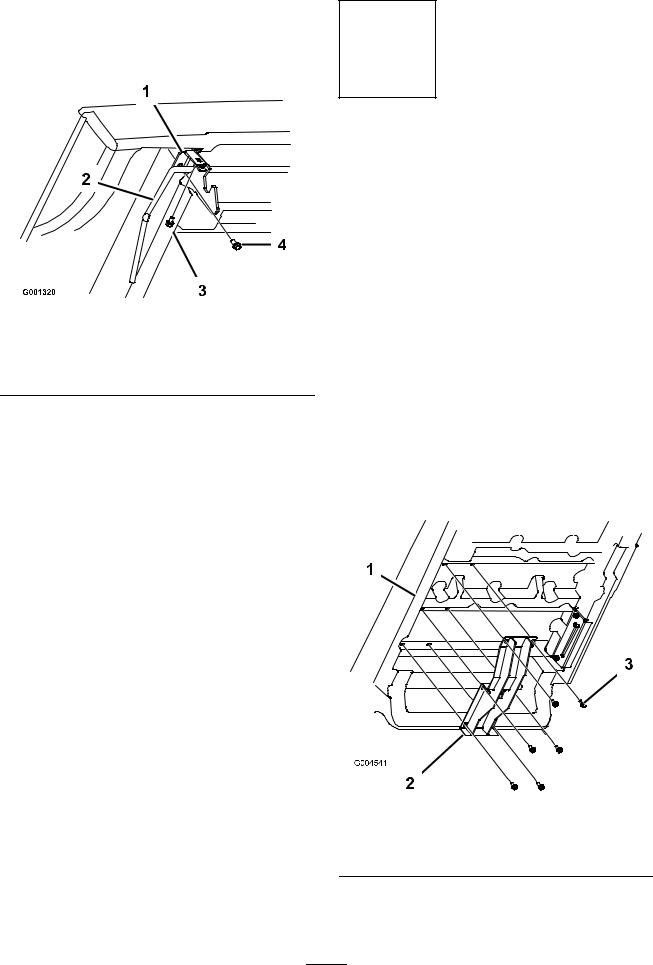
Remove the 2 flange head screws securing each side of the latch rod bracket to the front of the rear frame (Figure 2).
|
|
Figure 2 |
|
1. |
Latch rod bracket |
3. |
Latch rod |
2. |
Latch hook |
4. |
Spring |
For machines with Serial numbers 260000001 and up:
2
Remove the 2 flange head screws securing each side of the latch rod bracket to the underside and front face of the box (). Retain all parts for future use.
Figure 3
1. |
Latch rod bracket |
3. |
Flange head screw, inside |
|
|
|
front face of box |
2. |
Latch rod |
4. |
Flange head screw, |
underside of box
Step
2
Installing the Bed Lift
Parts needed for this step:
1 |
Lift bracket, upper |
4 |
Flange head screw (5/16 x 3/4 inch) |
1 |
Lift cylinder support |
1 |
Lift actuator |
2 |
U-bolts |
6 |
Flange nut (3/8 inch) |
2 |
Carriage bolts (3/8 x 3/4 inch) |
1 |
Clevis pin, short |
1 |
Cotter pin |
Procedure
1.Remove the screws from the braces on the underside of the box in the positions shown in (Figure 4).
2.Mount the upper lift bracket to the underside of the box with 6 flange head screws (5/16 x 3/4 inch) from loose parts and removed previously. Position the bracket as shown in Figure 4.
|
Figure 4 |
1. Bed |
3. Flange head screw, 5/16 x |
|
3/4 inch |
2.Upper lift bracket
3.Loosely mount the lift cylinder support to the right end of the rear axle with 2 U-bolts
3
 Loading...