

Page 1

Customer Service Bulletin
Commercial Business Group
Workman® 3200 & 4200 Series Vehicles
Model/Serial Range: Model Number: Serial Numbers:
07200 30101 - 79999
07202 50101 - 79999
07216 50101 - 79999
Subject: Fuel from Carburetor may Flood Crankcase.
Fuel may enter the carburetor throat through a fuel return line when the engine is off
causing fuel to enter the crankcase and the engine to run poorly. This condition is most
often the result of debris from the fuel that lodges between the needle and seat, which
can prevent the needle and seat from sealing properly.
If your unit experiences this situation, the fuel return line may be relocated as described
in the attached instructions. Carburetor cleaning instructions are also included. Further
details regarding this bulletin are available through your local Toro distributor.
Ref: 04-02 Copyright, 1998. The Toro Company
Page 2
Workman® 3200 & 4200 Series
Relocating Fuel System Return Line - Carburetor Cleaning
Relocating the Fuel System Return Line
1. Disconnect negative battery cable from machine.
2. Drain fuel from fuel tank into an approved gasoline container.
3. Disconnect fuel lines and sending unit electrical connection and remove the tank
from the machine.
4. Fill the tank with water.
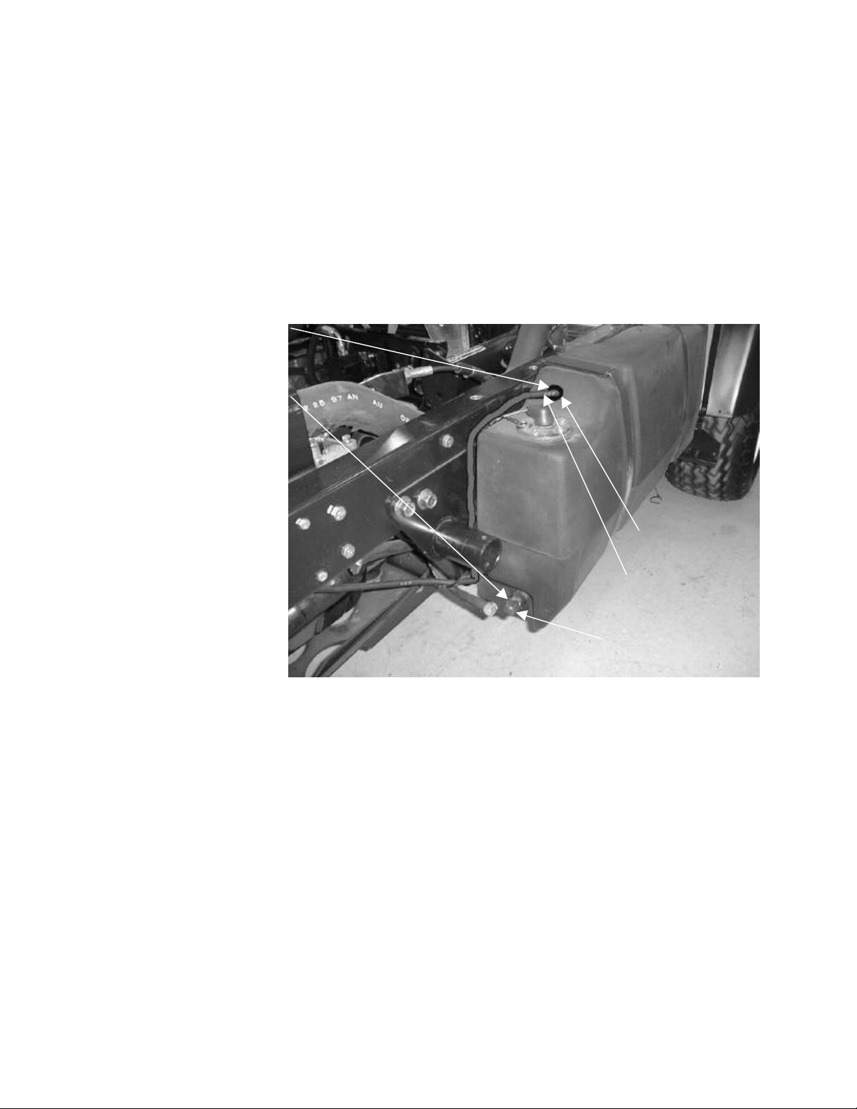
5. Drill 33/64” (13mm)
hole on flat surface
as shown in picture.
6. Loosen clamp and
unscrew fuel return
line fitting from
bottom of tank.
Discard fitting.
7. Drain water from fuel
tank and purge tank
of all water and
debris by using
compressed air for
several minutes.
8. Install fuel tank on
machine and
reconnect sending
unit electrical
connection.
9. Install Grommet (46-6560) into hole in fuel tank.
10. Press in Fitting (98-2952) into Grommet (46-6560).
11. Plug existing fuel tank return line fitting with Pipe Plug (281-10). Apply PTFE tape
or equivalent to plug before installing into tank. Tighten clamp.
12. Install new Fuel Return Line (93-2298) into Fitting (98-2952).
13. Route Fuel Return Line (93-2298) along inside vertical edge of fuel tank through
previous return line tie wrap to the carburetor.
Fitting
(98-2952)
Fuel Return Line
(93-2298)
Pipe Plug
(281-10)
Page 3

Mitsubishi 3G83 Carburetor Cleaning Instructions
Remove the carburetor from the machine. Disassemble the carburetor and thoroughly clean out
the Fuel Inlet System including the Fuel Inlet Chamber, Inlet Screen, Main Jet Holder Assembly,
Float Chamber Cover Assembly, Float, Needle Valve and Seat. Clean the remainder of the
carburetor body in a small container using clean, fresh solvent or carburetor cleaner. Used
solvent can have debris that can enter the small passages of the carburetor. It is not
recommended to use compressed air and force solvent into carburetor passages. It is
recommended by Mikuni to use a suction action to pull debris out of the carburetor passages.
Fuel Inlet Chamber
The fuel system inlet line and return line is located on the
side of the carburetor. Remove the inlet cover plate.
Thoroughly clean this chamber using fresh solvent and
reinstall cover plate.
Inlet Screen
The Inlet Screen is mounted on the bottom of the Needle Valve Seat.
Rinse the Inlet Screen in fresh solvent and clean out by blowing
compressed air through the screen in the opposite direction of fuel flow.
Doing so will dislodge any debris buildup. Re-rinse Needle Valve Seat in
clean solvent and re-install in carburetor. If the screen is damaged, or
cannot be cleaned, replace by installing Needle Valve Kit ((92-5140)
Main Jet Holder Assembly
The Main Jet Holder Assembly houses the Main Jet, Pilot Jet and
Power Jet and is located in the float chamber assembly. Remove
jets from holder assembly and clean using fresh solvent. If the jets
are corroded or cannot be cleaned using solvent, replace them by
installing Main Jet Holder Assembly (92-5132).
IMPORTANT: DO NOT use a wire to clean out any jets or
passages within the carburetor. A wire may damage the jet and
prevent proper engine operation.
Float Chamber Cover Assembly, Float, Needle Valve
and Seat.
Remove the Float Chamber Cover Assembly, Float Assembly,
and Needle Valve and clean using fresh solvent. If the entire
Float Chamber Cover, Float Assembly, and Needle Valve
Assembly cannot be cleaned using solvent, replace the parts by
installing Float Chamber Assembly (92-5144), Needle Valve Kit
(92-5140), Float & Pin Kit (92-5127).
Page 4

Carburetor Passages
Throttle Valve
Throttle Link
Piston Valve
Auto Choke
Acceleration
Main & Power
Choke Valve
Choke Pull-Off
Clean out the carburetor passages by using compressed air
through an air gun as illustrated. The air gun will provide a
suction that will pull debris out of the passages instead of forcing
the debris deeper into the carburetor.
When cleaning the carburetor, the following items should not be disassembled
due to adjustment and re-assembly concerns.
Pump Rod
System
Set Screws
Related Parts
Nozzles
Assembly
Set-Screws
Diaphragm
 Loading...