

Page 1

FORM NO. 3315–999EN Rev. A
Wheel Horse
12–38 XL
Lawn Tractor
Model No. 71202 – 3900001 & Up
Operator’s Manual
IMPORTANT: Read this manual carefully. It contains information about your
safety and the safety of others. Also become familiar with the controls and
their proper use before you operate the product.
Page 2
Introduction
Thank you for purchasing a Toro product.
All of us at Toro want you to be completely satisfied
with your new product, so feel free to contact your
local Authorized Service Dealer for help with service,
genuine Toro parts, or other information you may
require.
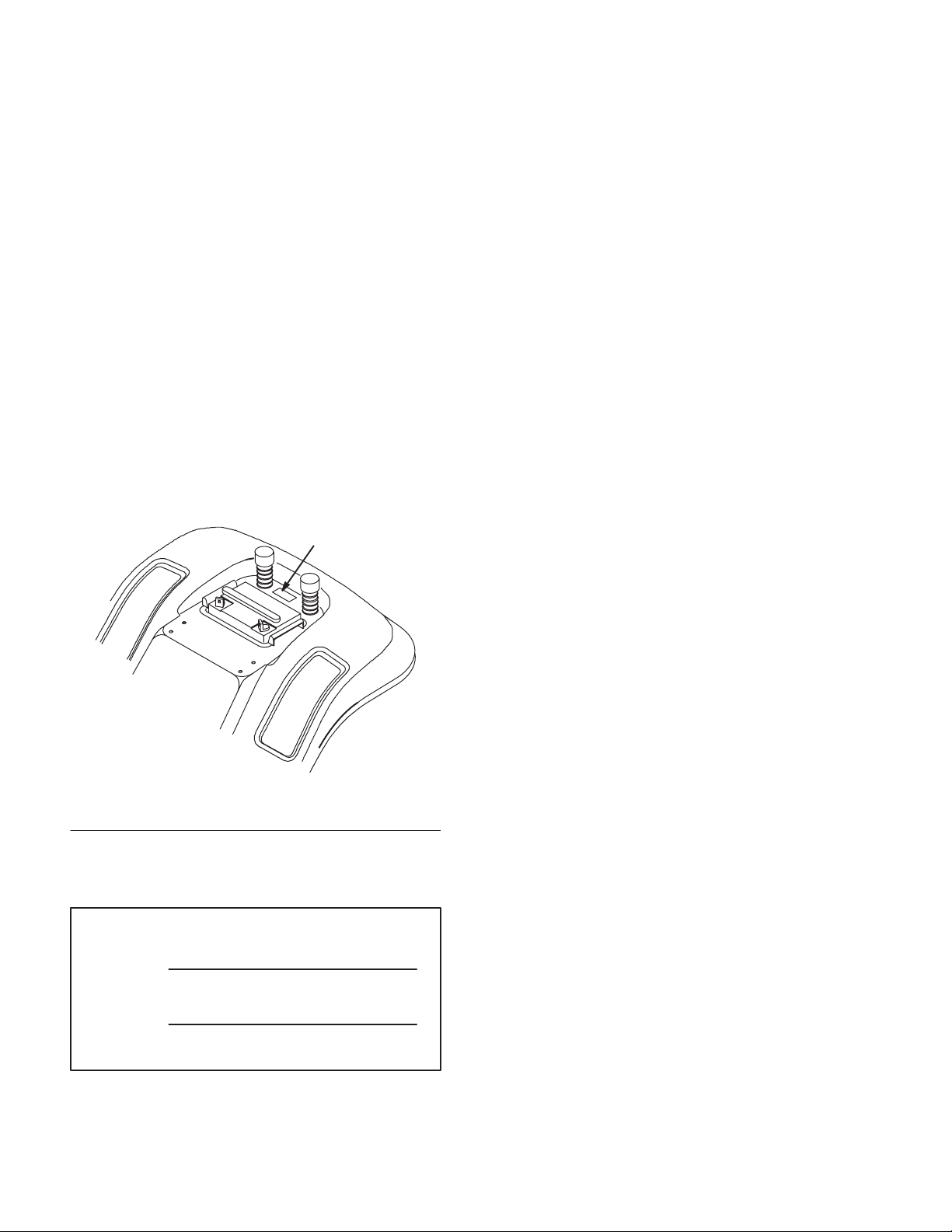
Whenever you contact your Authorized Service
Dealer or the factory, always know the model and
serial numbers of your product. These numbers will
help the Service Dealer or Service Representative
provide exact information about your specific
product. You will find the model and serial number
plate located in a unique place on the product as
shown below.
1
Read this manual carefully to learn how to operate
and maintain your product correctly. Reading this
manual will help you and others avoid personal injury
and damage to the product. Although Toro designs,
produces and markets safe, state-of-the-art products,
you are responsible for using the product properly
and safely. You are also responsible for training
persons who you allow to use the product about safe
operation.
The Toro warning system in this manual identifies
potential hazards and has special safety messages that
help you and others avoid personal injury, even death.
DANGER, WARNING and CAUTION are signal
words used to identify the level of hazard. However,
regardless of the hazard, be extremely careful.
DANGER signals an extreme hazard that will cause
serious injury or death if the recommended
precautions are not followed.
WARNING signals a hazard that may cause serious
injury or death if the recommended precautions are
not followed.
1. Model and Serial Number Plate
(under the seat)
For your convenience, write the product model and
serial numbers in the space below.
Model No:
Serial No.
CAUTION signals a hazard that may cause minor or
moderate injury if the recommended precautions are
not followed.
Two other words are also used to highlight
information. “Important” calls attention to special
mechanical information and “Note” emphasizes
general information worthy of special attention.
The left and right side of the machine is determined
by sitting on the seat in the normal operator’s
position.
Printed in USA
The Toro Company – 1993
All Rights Reserved
Page 3

Contents
Safety 2. . . . . . . . . . . . . . . . . . . . . . . . . . . . . . . . .
Safe Operating Practices 2. . . . . . . . . . . . . .
Slope Chart 5. . . . . . . . . . . . . . . . . . . . . . . . .
International Symbols 7. . . . . . . . . . . . . . . .
Gasoline and Oil 8. . . . . . . . . . . . . . . . . . . . . . . .
Recommended Gasoline 8. . . . . . . . . . . . . . .
Stabilizer/Conditioner 8. . . . . . . . . . . . . . . .
Filling the Fuel Tank 8. . . . . . . . . . . . . . . . .
Check Engine Oil Level 8. . . . . . . . . . . . . . .
Operation 9. . . . . . . . . . . . . . . . . . . . . . . . . . . . . .
Think Safety First 9. . . . . . . . . . . . . . . . . . .
Controls 9. . . . . . . . . . . . . . . . . . . . . . . . . . .
Parking Brake 9. . . . . . . . . . . . . . . . . . . . . . .
Positioning the Seat 10. . . . . . . . . . . . . . . . . .
Positioning the Tilt Steering Wheel 10. . . . . .
Headlights 10. . . . . . . . . . . . . . . . . . . . . . . . .
Using the Blade Control (PTO) 11. . . . . . . . .
Setting the Height-of-Cut 11. . . . . . . . . . . . . .
Adjusting Mower Wheels 11. . . . . . . . . . . . .
Starting and Stopping the Engine 12. . . . . . .
The Safety System 13. . . . . . . . . . . . . . . . . . .
Driving Forward or Backward 14. . . . . . . . . .
Selecting Ground Speeds 14. . . . . . . . . . . . . .
Stopping the Machine 14. . . . . . . . . . . . . . . .
Side Discharge or Mulch Grass 15. . . . . . . . .
Installing the Discharge Cover 15. . . . . . . . . .
Tips for Mowing Grass 16. . . . . . . . . . . . . . .
Page
Page
Maintenance 17. . . . . . . . . . . . . . . . . . . . . . . . . . . .
Service Interval Chart 17. . . . . . . . . . . . . . . .
Greasing and Lubrication 18. . . . . . . . . . . . . .
Tire Pressure 19. . . . . . . . . . . . . . . . . . . . . . . .
Brake 19. . . . . . . . . . . . . . . . . . . . . . . . . . . . .
Wiring Diagram 20. . . . . . . . . . . . . . . . . . . . .
Fuse 21. . . . . . . . . . . . . . . . . . . . . . . . . . . . . .
Headlights 21. . . . . . . . . . . . . . . . . . . . . . . . .
Battery 22. . . . . . . . . . . . . . . . . . . . . . . . . . . .
Spark Plug 24. . . . . . . . . . . . . . . . . . . . . . . . .
Fuel Tank 25. . . . . . . . . . . . . . . . . . . . . . . . . .
Fuel Filter 25. . . . . . . . . . . . . . . . . . . . . . . . . .
Throttle and Choke Control 26. . . . . . . . . . . .
Carburetor 27. . . . . . . . . . . . . . . . . . . . . . . . .
Air Cleaner 28. . . . . . . . . . . . . . . . . . . . . . . . .
Engine Oil 30. . . . . . . . . . . . . . . . . . . . . . . . .
Cutting Blade 32. . . . . . . . . . . . . . . . . . . . . . .
Removing the Mower 34. . . . . . . . . . . . . . . . .
Installing the Mower 36. . . . . . . . . . . . . . . . .
Blade Drive Belt 38. . . . . . . . . . . . . . . . . . . . .
Side-to-Side Mower Leveling 39. . . . . . . . . .
Front-to-Rear Blade Slope 40. . . . . . . . . . . . .
Storage 42. . . . . . . . . . . . . . . . . . . . . . . . . . . .
Troubleshooting 43. . . . . . . . . . . . . . . . . . . . . . . . .
1
Page 4

Safety
This machine meets or exceeds the B71.1–1990
specifications of the American National Standards
Institute, in effect at the time of production.
However, improper use or maintenance by the
operator or owner can result in injury. To reduce
the potential for injury, comply with these safety
instructions and always pay attention to the safety
alert
WARNING, or DANGER—“personal safety
instruction.” Failure to comply with the
instruction may result in personal injury or death.
symbol, which means CAUTION,
Safe Operating Practices
This product is capable of amputating hands and feet
and throwing objects. Always follow all safety
instructions to avoid serious injury or death.
POTENTIAL HAZARD
• Engine exhaust contains carbon monoxide,
which is an odorless, deadly poison.
WHAT CAN HAPPEN
• Carbon monoxide can kill you and is also
known to the State of California to cause
birth defects.
HOW TO AVOID THE HAZARD
• Do not run engine indoors or in an enclosed
area.
General Operation
1. Read, understand, and follow all instructions in
the operator’s manual and on the machine before
starting.
2. Allow only responsible adults who are familiar
with the instructions to operate the machine.
3. Clear the area of objects such as rocks, toys,
wire, etc., which could be picked up and thrown
by the blade.
4. Be sure the area is clear of other people before
mowing. Stop the machine if anyone enters the
area.
5. Never carry passengers.
6. Do not mow in reverse unless absolutely
necessary. Always look down and behind before
and while backing.
7. Be aware of the mower discharge direction and
do not point it at anyone. Do not operate the
mower without either the entire grass catcher or
the guard in place.
8. Slow down before turning. Sharp turns on any
terrain may cause loss of control.
9. Never leave a running machine unattended.
Always turn off blades, set parking brake, stop
engine, and remove key before dismounting.
10. Turn off blades when not mowing.
11. Keep hands, feet, hair and loose clothing away
from attachment discharge area, underside of
mower and any moving parts while engine is
running.
12. Stop the engine before removing the grass
catcher or unclogging the chute.
2
Page 5

Safety
13. Mow only in daylight or good artificial light.
14. Do not operate the machine while under the
influence of alcohol or drugs.
15. Watch for traffic when operating near or crossing
roadways.
16. Use extra care when loading or unloading the
machine into a trailer or truck.
17. Do not touch equipment or attachment parts
which may be hot from operation. Allow to cool
before attempting to maintain, adjust or service.
Slope Operation
Slopes are a major factor related to loss-of-control
and tip-over accidents, which can result in severe
injury or death. All slopes require extra caution. If
you cannot back up the slope or if you feel uneasy on
it, do not mow it.
• Keep all movement on slopes slow and gradual.
Do not make sudden changes in speed or
direction.
• Avoid starting or stopping on a slope. If tires
lose traction, disengage the blades and proceed
slowly straight down the slope.
DO NOT
• Do not operate machine on hillsides or slopes
exceeding 15°.
• Avoid turning on slopes. If you must turn, turn
slowly and gradually downhill, if possible.
• Do not mow near drop-offs, ditches, or
embankments. The machine could suddenly turn
over if a wheel goes over the edge of a cliff or
ditch, or if an edge caves in.
• Do not mow on wet grass. Reduced traction
could cause sliding.
DO
• Mow up and down slopes greater than 5°, not
across.
• Mow downhill only on slopes above 10°, never
mow uphill. If a steep slope must be ascended,
back up the hill, and drive forward down the hill,
keeping the machine in gear.
• Remove obstacles such as rocks, tree limbs, etc.
from the mowing area. Watch for holes, ruts or
bumps, as uneven terrain could overturn the
machine. Tall grass can hide obstacles.
• Use slow speed. Choose a low gear so that you
will not have to stop or shift while on the slope.
• Follow the manufacturer’s recommendations for
wheel weight or counterweights to improve
stability.
• Use extra care with grass catchers or other
attachments. These can change the stability of
the machine.
• Do not try to stabilize the machine by putting
your foot on the ground.
• Do not use a grass catcher on steep slopes.
Heavy grass bags could cause loss of control or
overturn the machine.
3
Page 6

Safety
Children
Tragic accidents can occur if the operator is not alert
to the presence of children. Children are often
attracted to the machine and the mowing activity.
Never assume that children will remain where you
last saw them. The following requirements must be
followed to prevent injury to children.
1. Keep children out of the mowing area and under
the watchful care of another responsible adult.
2. Be alert and turn the machine off if children
enter the area.
3. Before and while backing, look behind and down
for small children.
4. Never carry children. They may fall off and be
seriously injured or interfere with safe machine
operation.
5. Never allow children to operate the machine.
6. Use extra care when approaching blind corners,
shrubs, trees, the end of a fence or other objects
that may obscure vision.
4. Keep nuts and bolts tight, especially the blade
attachment bolts. Keep equipment in good
condition.
5. Never tamper with safety devices. Check safety
systems for proper operation before each use.
6. Keep the machine free of grass, leaves, or other
debris build-up. Clean up oil or fuel spillage.
Allow the machine to cool before storing.
7. Stop and inspect the equipment if you strike an
object. Repair, if necessary, before restarting.
8. Grass catcher components are subject to wear,
damage and deterioration, which could expose
moving parts or allow objects to be thrown.
Frequently check components and replace with
manufacturer’s recommended parts, when
necessary.
9. Mower blades are sharp and can cut. Wrap the
blade(s) or wear gloves, and use extra caution
when servicing them.
10. Use only genuine Toro replacement parts to
ensure that original standards are maintained.
Service
1. Stop the engine and disconnect spark plug
wire(s) before performing any service, repairs,
maintenance or adjustments.
2. Use extra care when handling gasoline and other
fuels. They are flammable and vapors are
explosive.
A. Use only an approved container.
B. Never remove the gas cap or add fuel when
the engine is running. Allow the engine to
cool before refueling. Do not smoke.
C. Never refuel the machine indoors.
D. Never store the machine or fuel container
inside where there is an open flame, such as
near a water heater or furnace.
3. Never run a machine inside a closed area.
11. Check brake operation frequently. Adjust and
service as required.
12. Battery acid is poisonous and can cause burns.
Avoid contact with skin, eyes and clothing.
Protect your face, eyes and clothing when
working with a battery.
13. Battery gases can explode. Keep cigarettes,
sparks and flames away from battery.
4
Page 7
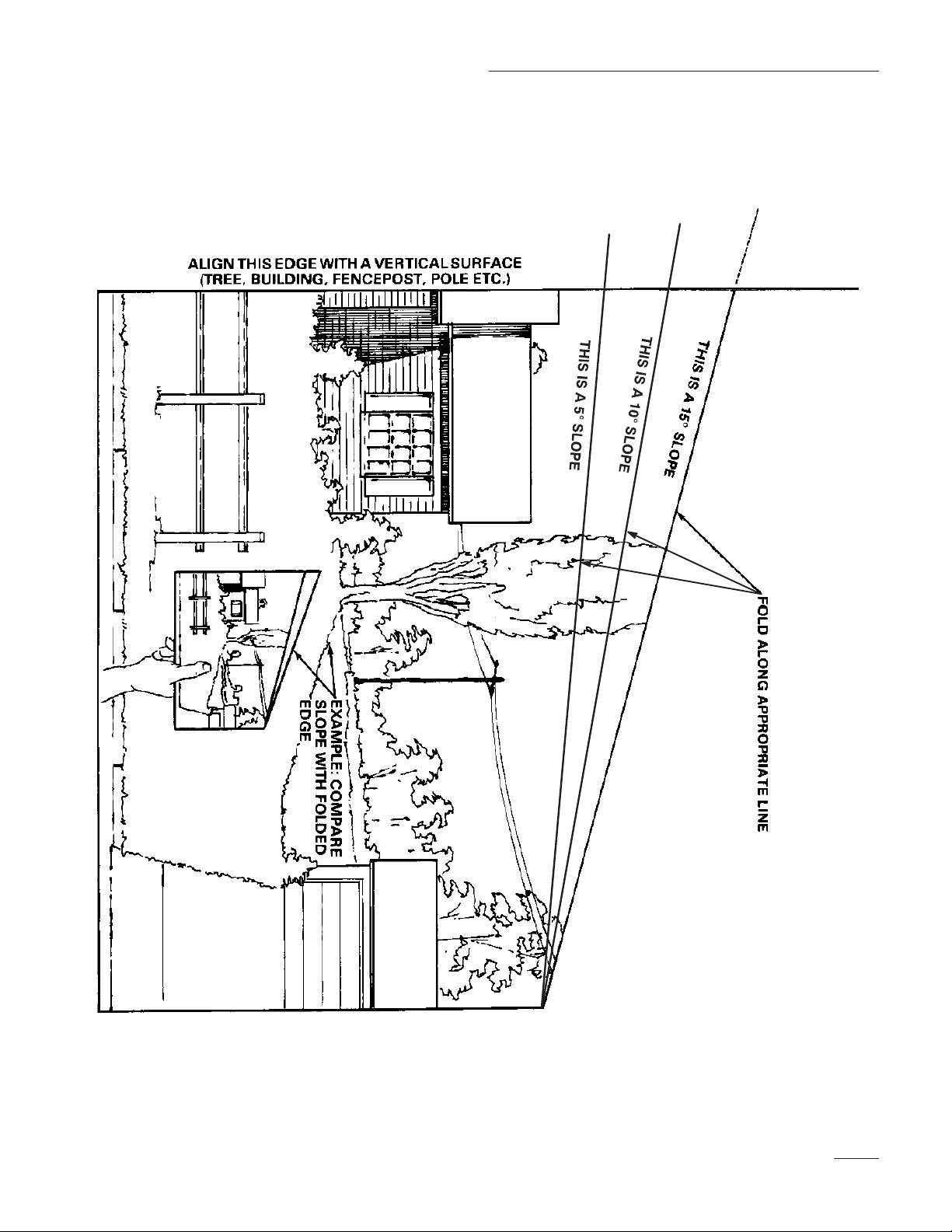
Slope Chart
Read all safety instructions on pages 2–4.
Safety
5
Page 8

6
Page 9
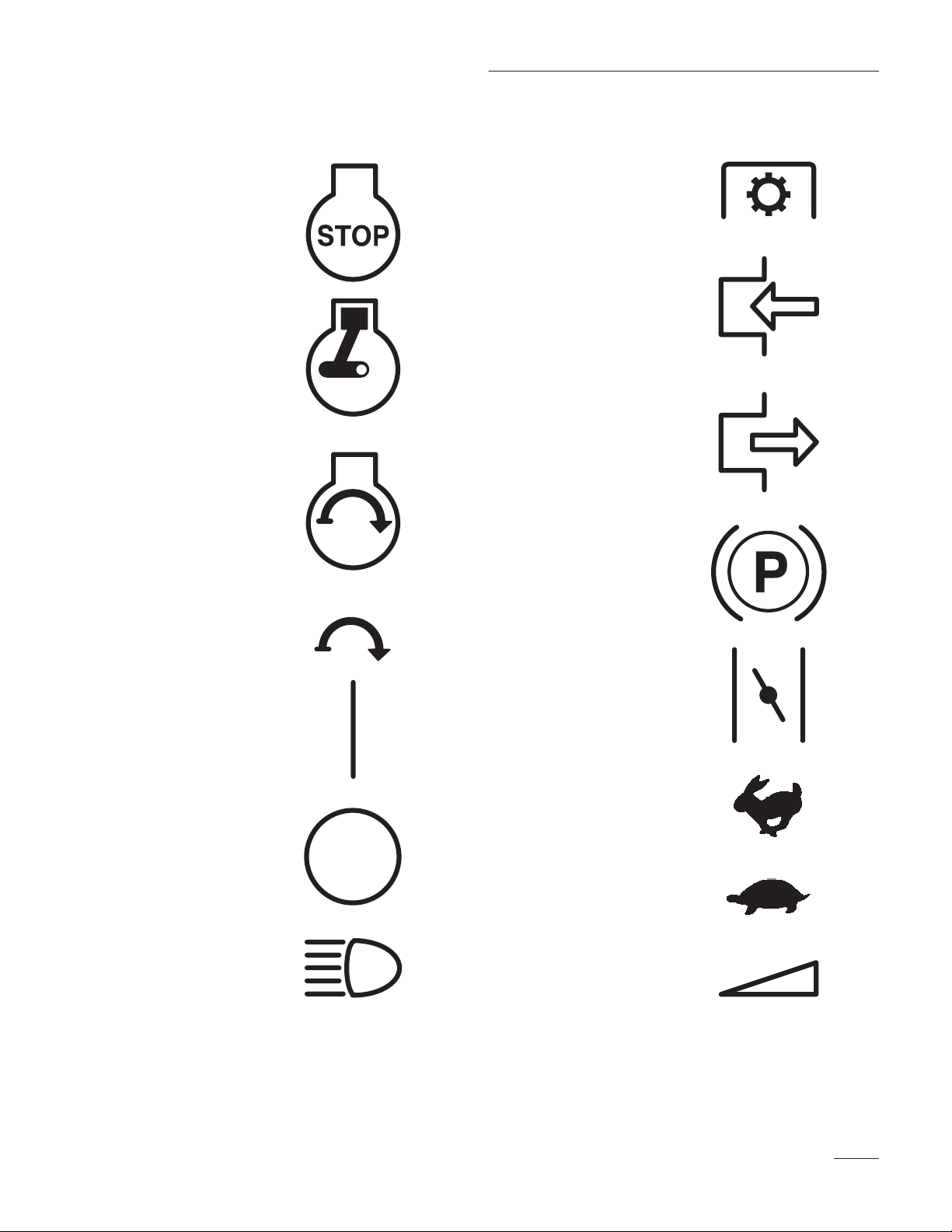
International Symbols
ENGINE STOP
ENGINE RUN
Safety
PTO
ENGAGE
DISENGAGE
ENGINE START
START
SWITCH/MECHANISM
ON/START
OFF/STOP
HEADLIGHTS –
MAIN BEAM
PARKING BRAKE
CHOKE
FAST
SLOW
CONTINUOUSLY
VARIABLE – LINEAR
7
Page 10

Gasoline and Oil
Recommended Gasoline
Use UNLEADED Regular Gasoline suitable for
automotive use (85 pump octane minimum). Leaded
regular gasoline may be used if unleaded regular is
not available.
IMPORTANT: Never use methanol, gasoline
containing methanol, or gasohol containing
more than 10% ethanol because the fuel
system could be damaged. Do not mix oil with
gasoline.
POTENTIAL HAZARD
• In certain conditions gasoline is extremely
flammable and highly explosive.
WHAT CAN HAPPEN
• A fire or explosion from gasoline can burn
you, others, and cause property damage.
HOW TO AVOID THE HAZARD
• Use a funnel and fill the fuel tank outdoors,
in an open area, when the engine is cold.
Wipe up any gasoline that spills.
• Do not fill the fuel tank completely full.
Add gasoline to the fuel tank until the level
is 1/4” to 1/2” (6 mm to 13 mm) below the
bottom of the filler neck. This empty space
in the tank allows gasoline to expand.
• Never smoke when handling gasoline, and
stay away from an open flame or where
gasoline fumes may be ignited by a spark.
• Store gasoline in an approved container
and keep it out of the reach of children.
Never buy more than a 30-day supply of
gasoline.
Stabilizer/Conditioner
Toro Stabilizer/Conditioner
Add the correct amount of Toro Gas
Stabilizer/Conditioner to the gas. Using Toro
Stabilizer/Conditioner or an isopropyl-based
conditioner/stabilizer in the machine:
• Keeps gasoline fresh during storage
• Cleans the engine while it runs
• Eliminates gum-like buildup in the fuel system,
which causes hard starting
IMPORTANT: Never use fuel additives
containing methanol or ethanol.
Filling the Fuel Tank
1. Shut the engine off and open the hood.
2. Clean around the fuel tank cap and remove the
cap. Use a funnel and add unleaded regular
gasoline to the fuel tank, until the level is 1/4 to
1/2 inch (6 mm to 13 mm) below the bottom of
the filler neck. This space in the tank allows
gasoline to expand. Do not fill the fuel tank
completely full.
3. Install the fuel tank cap securely. Wipe up any
gasoline that may have spilled.
4. Close the hood.
Check Engine Oil Level
Before you start the engine and use the machine,
check the oil level in the engine crankcase; refer to
Checking Oil Level, page NO TAG.
8
Page 11
Operation
Think Safety First
Please carefully read all the safety instructions on
pages 2–7. Knowing this information could help you,
your family, pets or bystanders avoid injury.
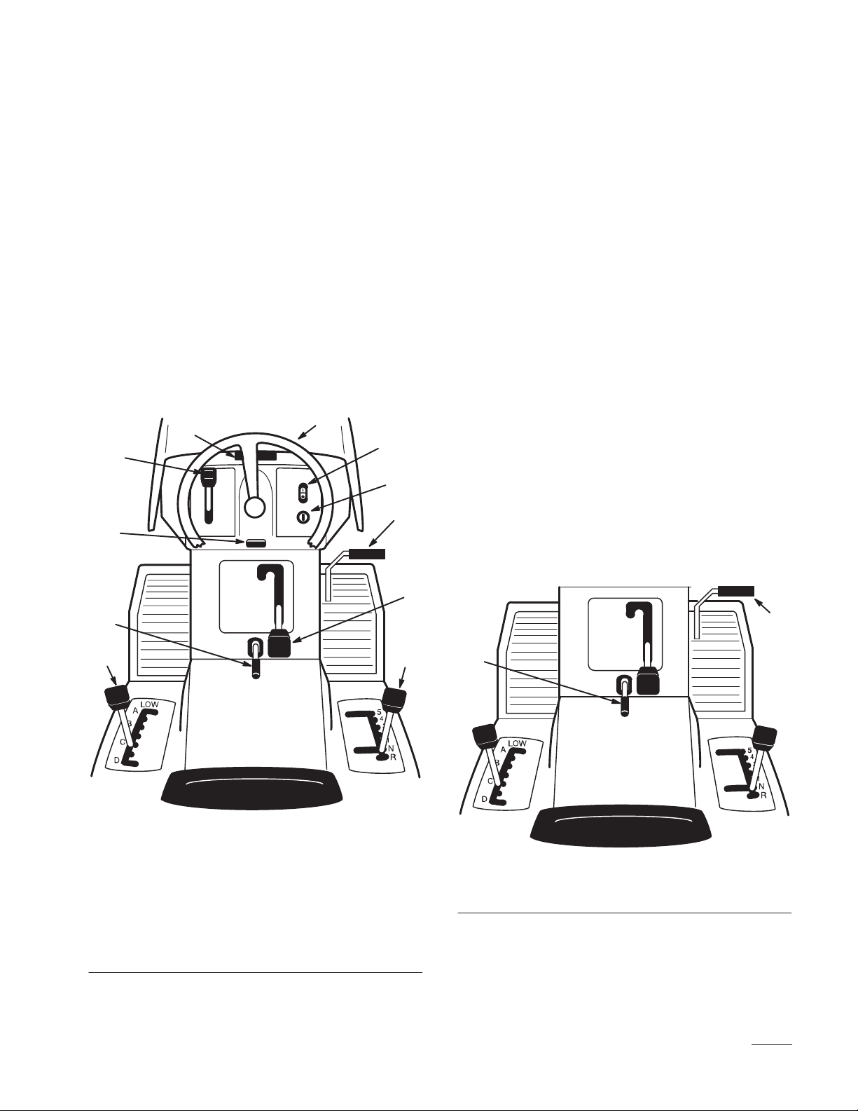
Controls
Become familiar with all the controls (Fig. 1) before
you start the engine and operate the machine.
11
10
9
1
2
3
4
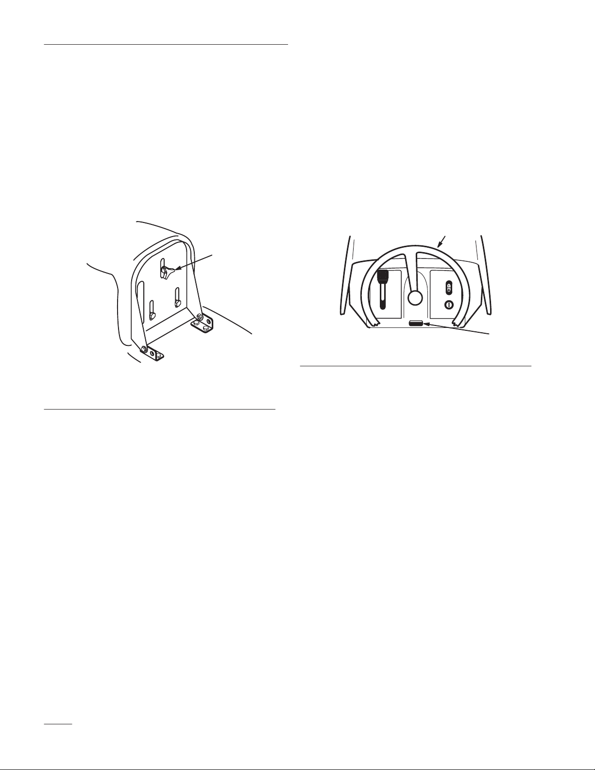
Parking Brake
Always set the parking brake when you stop the
machine or leave it unattended.
Setting the Parking Brake
1. Push the clutch/brake pedal (Fig. 2) down and
hold it in the depressed position.
2. Lift the parking brake lever (Fig. 2) up and
gradually take your foot off the clutch/brake
pedal. The clutch/brake pedal should stay in the
depressed (locked) position.
Releasing the Parking Brake
1. Push down on the clutch/brake pedal (Fig. 2).
The parking brake lever should release.
2. Gradually release the clutch/brake pedal.
8
7
1. Steering wheel
2. Light switch—on/off
(selected models)
3. Ignition switch
4. Clutch/brake pedal
5. Blade control (PTO)
6. Ground speed selector
Figure 1
7. Height-of-cut lever
(deck lift)
8. Parking brake lever
9. Tilt button (selected
models)
10. Throttle lever
11. Hood opening
5
1
6
2
Figure 2
1. Clutch/brake pedal 2. Parking brake lever
9
Page 12
Operation
Positioning the Seat
The seat can move forward and backward. Position
the seat where you have the best control of the
machine and are most comfortable.
1. Raise the seat and loosen the adjustment knob
(Fig. 3).
2. Move the seat to the desired position and tighten
the knob.
1
Positioning the
Tilt Steering Wheel
On select models the steering wheel tilts up and
down. Position the steering wheel where you have the
best control of the machine and are most comfortable.
1. Push in on the tilt button (Fig. 4).
2. Move the steering wheel to any of three
positions; then release the button.
2
Figure 4
1. Tilt button 2. Steering wheel
1
Figure 3
1. Adjustment knob
Headlights
Headlights are optional on some models. A
dash-mounted “ON/OFF” switch (Fig. 1) controls the
headlights. The lights only shine while the engine is
running and the switch is “ON.”
10
Page 13
Operation
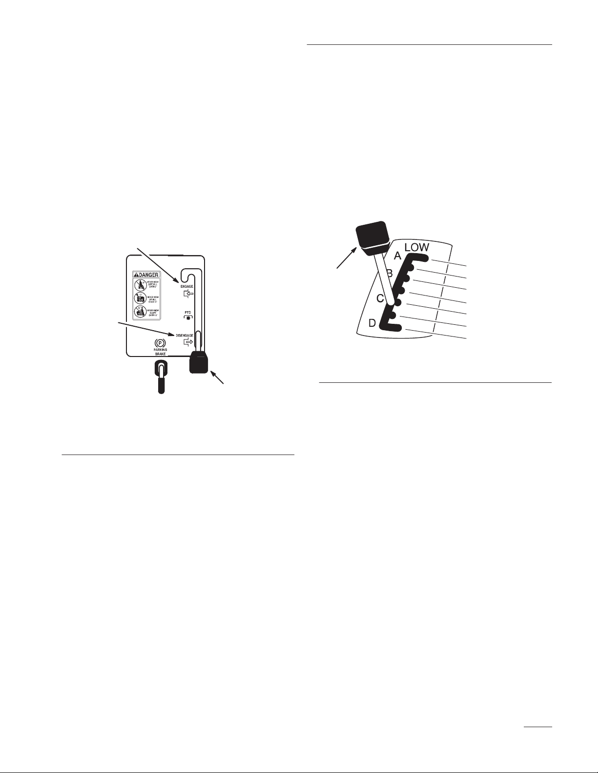
Using the Blade Control (PTO)
The blade control (PTO) engages and disengages
power to the blade(s).
Engaging the Blade(s)
1. Depress the clutch/brake pedal to stop the
machine.
2. Move the blade control (PTO) to “ENGAGED”
(Fig. 5).
2
1
Setting the Height-of-Cut
The height-of-cut lever (deck lift) is used to raise and
lower the mower to the desired cutting height.
1. The cutting height may be set in one of seven
positions from approximately 1 to 4 inches
(25 to 102 mm).
2. Pull on the height-of-cut lever (deck lift) and
move it to the desired position (Fig. 6).
1
Figure 6
1. Height-of-cut lever (deck lift)
1” (25 mm)
1–1/2” (38 mm)
2” (51 mm)
2–1/2” (64 mm)
3” (76 mm)
3–1/2” (89 mm)
4” (102 mm)
3
Figure 5
1. Disengaged
2. Engaged
3. Blade control (PT O)
Disengaging the Blade(s)
1. Depress the clutch/brake pedal to stop the
machine.
2. Move the blade control (PTO) to
“DISENGAGED” (Fig. 5).
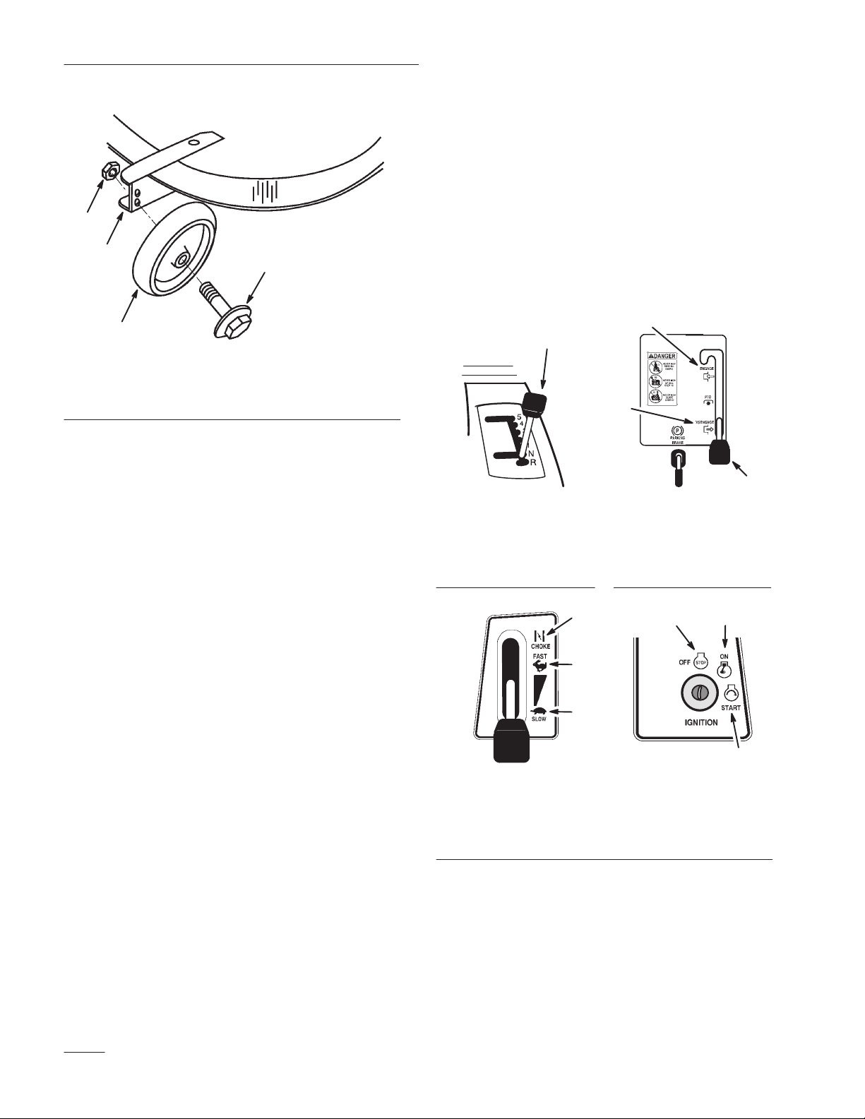
Adjusting Mower Wheels
The mower front wheels are to guide it over uneven
ground. The height of these wheels can be changed to
closer match the height-of-cut selected for the mower.
1. To change the height of mower wheels remove
wheel mounting bolt and change hole into which
it is mounted (Fig. 7).
2. Use the top hole for low height-of-cut and the
bottom hole for high height-of-cut (Fig. 7).
11
Page 14
Operation
IMPORTANT: If the engine does not start
after 30 seconds of continuous cranking, turn
the ignition key to “OFF” and let the starter
motor cool; refer to Troubleshooting,
page NO TAG.
3
2
1
Figure 7
1. Wheel
2. Wheel bracket
4
3. Locknut
4. Wheel bolt
Starting and Stopping
the Engine
Starting
1. Sit down on the seat.
2. Set the parking brake; refer to Setting the
Parking Brake, page 9.
7. After the engine starts, slowly move the throttle
lever to “FAST” (Fig. 10). If the engine stalls or
hesitates, move the throttle lever back to
“CHOKE” for a few seconds. Then move the
throttle lever to “FAST.” Repeat this as required.
2
1
1
3
Figure 8
1. Ground speed
selector
1
Figure 9
1. Disengaged
2. Engaged
3. Blade control (PT O)
3
2
Note: The engine will not start unless you set
the parking brake or fully depress the
clutch/brake pedal.
3. Move the ground speed selector into neutral “N”
(Fig. 8).
4. Move the blade control (PTO) to
“DISENGAGED” (Fig. 9).
5. Move the throttle lever to “CHOKE” (Fig. 10).
Note: An engine that has been running and is
warm may not require step 5.
6. Turn the ignition key clockwise and hold it in
the “START” position (Fig. 11). When the
engine starts, release the key.
12
Figure 10
1. Choke
2. Fast
3. Slow
2
3
1
Figure 11
1. Start
2. On
3. Off
Page 15

Operation
Stopping
1. Move the throttle lever to “SLOW” (Fig. 10).
2. Turn the ignition key to “OFF” (Fig. 11).
Note: If the engine has been working hard or
is hot, let it idle for a minute before
turning the ignition key “OFF.” This
helps cool the engine before it is
stopped. In an emergency, the engine
may be stopped by turning the ignition
key to “OFF.”
The Safety System
Understanding the Safety System
The safety system is designed to prevent the engine
from starting unless:
• You are sitting on the seat
1. Move the ground speed selector into neutral “N.”
Set the parking brake. Move the blade control
(PTO) to “ENGAGED.” Now turn the ignition
key to “START”; the engine should not crank.
2. With the ground speed selector in neutral “N,”
move the blade control (PTO) to
“DISENGAGED” and release the parking brake.
Now turn the ignition key to “START”; the
engine should not crank.
3. With the ground speed selector in neutral “N,”
set the parking brake and move the blade control
(PTO) to “DISENGAGED.” Now start the
engine. While the engine is running, release the
parking brake and rise slightly from the seat; the
engine should stop.
• The clutch/brake pedal is depressed
• The blade control (PTO) is “DISENGAGED”
The safety system is designed to stop the engine if
you rise from the seat when the clutch/brake pedal is
released or the blade is “ENGAGED.”
Testing the Safety System
Test the safety system before you use the machine
each time. If the safety system does not operate as
described below, have an Authorized Service Dealer
repair the safety system immediately.
13
Page 16

Operation
Driving Forward or Backward
The throttle control regulates the engine speed as
measured in rpm (revolutions per minute).
To go forward or backward, depress the clutch/brake
pedal. Move the ground speed selector to the desired
forward speed or reverse. As you slowly release the
pedal, the machine will begin to move. Steer the
machine with the steering wheel.
POTENTIAL HAZARD
• If you release the clutch/brake pedal too
quickly when the ground speed selector is
in gear, you could suddenly put the
machine in motion.
WHAT CAN HAPPEN
• Sudden engagement of the machine’s drive
system could cause you to lose control.
HOW TO AVOID THE HAZARD
• Always release the clutch/brake pedal
slowly when starting the machine in motion
(forward or reverse).
Stopping the Machine
To stop the machine, depress the clutch/brake pedal,
shift into neutral, disengage the blade control (PTO),
and turn the ignition key to “OFF” to stop the engine.
Also set the parking brake if you leave the machine
unattended; refer to Setting the Parking Brake,
page 9. Remember to remove the key from the
ignition switch.
POTENTIAL HAZARD
• Someone could move or attempt to operate
the tractor while it is unattended.
WHAT CAN HAPPEN
• Children or bystanders may be injured if
they use the tractor.
HOW TO AVOID THE HAZARD
• Always remove the ignition key and set the
parking brake when leaving the machine
unattended, even if just for a few minutes.
Selecting Ground Speeds
IMPORTANT: To avoid transmission
damage, always depress the clutch/brake
pedal before shifting into or out of reverse.
Always start the machine in motion by depressing the
clutch/brake pedal and shifting into the desired speed.
Once the machine is in motion, you can shift into any
forward speed without depressing the clutch/brake
pedal. In most conditions, the machine is powerful
enough to move out in any speed. If it will not move
out in a selected speed (i.e., #5) due to a heavy load,
use a lower speed (i.e., #2).
14
Page 17

Operation
Side Discharge
or Mulch Grass
POTENTIAL HAZARD
• Without the grass deflector, discharge
cover, or complete grass catcher assembly
mounted in place, you and others are
exposed to blade contact and thrown
debris.
WHAT CAN HAPPEN
• Contact with rotating mower blade(s) and
thrown debris will cause injury or death.
HOW TO AVOID THE HAZARD
• NEVER remove the grass deflector from
the mower because the grass deflector
routes material down toward the turf. If the
grass deflector is ever damaged, replace it
immediately.
• Never put your hands or feet under the
mower.
• Never try to clear discharge area or mower
blades unless you move the blade control
(PTO) to “DISENGAGED” and rotate the
ignition key to “OFF.” Also remove the key
and pull the wire off the spark plug.
1. The mower has a hinged grass deflector that
disperses clippings to the side and down toward
the turf.
Installing the
Discharge Cover
To convert from side discharge to a mulching mower,
install the discharge cover into the opening at the side
of the mower.
1. Lift the grass deflector and slide the tabs on top
of the discharge cover under the grass deflector
retaining rod. Rotate the discharge cover down
over the opening, and onto the lower lip of the
mower (Fig. 12).
2. Secure the discharge cover to the lower lip of the
mower with bolts and nuts (Fig. 12).
1
2
6
6
5
5
1. Grass deflector
2. Tabs under rod
3. Discharge cover
3
Figure 12
4. Lower lip
5. Bolt
6. Nut
4
2. To mulch grass clippings you must install the
discharge cover (optional on some models) into
the opening in the side of the mower; refer to
Installing the Discharge Cover, page 15.
3. To convert back to a side discharge mower,
remove the discharge cover and lower the grass
deflector over the discharge opening.
15
Page 18

Operation
Tips for Mowing Grass
Fast Throttle Setting
For best mowing and maximum air circulation,
operate the engine at “FAST.” Air is required to
thoroughly cut grass clippings, so do not set the
height-of-cut too low or totally surround the mower
by uncut grass. Always try to have one side of the
mower free from uncut grass, which allows air to be
drawn into the mower.
Cutting a Lawn for the First Time
Cut grass slightly longer than normal to ensure the
cutting height of the mower does not scalp any
uneven ground. However, the cutting height used in
the past is generally the best one to use. When cutting
grass longer than six inches tall, you may want to cut
the lawn twice to assure an acceptable quality-of-cut.
Cut 1/3 of the Grass Blade
It is best to cut only about 1/3 of the grass blade.
Cutting more than that is not recommended, unless
grass is sparse or it is late fall when grass grows more
slowly.
Avoid Cutting Too Low
If the cutting width of the mower is wider than the
mower you previously used, raise the cutting height
one notch to ensure uneven turf is not cut too short.
Long Grass
If the grass is ever allowed to grow slightly longer
than normal, or if it contains a high degree of
moisture, raise the cutting height higher than usual
and cut the grass at this setting. Then cut the grass
again using the lower, normal setting.
When Stopping
If the machine’s forward motion must be stopped
while mowing, a clump of grass clippings may drop
onto your lawn. To avoid this:
1. With the blade(s) “ENGAGED,” move onto a
previously cut area.
2. To disperse the clippings evenly, raise the mower
one or two height-of-cut settings while driving
forward with the blade(s) “ENGAGED.”
Keep the Underside of the Mower Clean
Mowing Direction
Alternate mowing direction to keep the grass standing
straight. This also helps disperse clippings which
enhances decomposition and fertilization.
Mow at Correct Intervals
Normally, mow every 4 days. But remember, grass
grows at different rates at different times. So to
maintain the same cutting height, which is a good
practice, mow more often in early spring. As the
grass growth rate slows in mid summer, mow less
frequently. If you cannot mow for an extended period,
first mow at a high cutting height; then mow again 2
days later at a lower height setting.
16
Clean clippings and dirt from the underside of the
mower after each use. If grass and dirt build up inside
the mower, cutting quality will eventually become
unsatisfactory.
Blade Maintenance
Maintain a sharp blade throughout the cutting season
because a sharp blade cuts cleanly without tearing or
shredding the grass blades. Tearing and shredding
turns grass brown at the edges, which slows growth
and increases the chance of disease. Every 30 days,
check the cutter blade(s) for sharpness and file down
any nicks.
Page 19

Maintenance
More often in
y, y
Service Interval Chart
Each
Service Operation
Oil—initial change X
Oil—periodic change X X
Oil—check level X
Safety System—check X X X X
Cutter Blade—check X X X
Brake—check X X X X
Chassis—grease X X
Foam Air Cleaner—service X X
Paper Air Cleaner—replace X
Spark Plug—check X X X
Belts—check for wear/cracks X
Gasoline—drain X
Engine—clean outside X X
Mower Housing—clean X X X
Chipped Surfaces—paint X
Use5Hours25Hours
Storage
Service
Spring
Service
Notes
dusty, dirty
conditions
Battery—check electrolyte X X X X X
Battery—charge, disconnect cables X
Fuel Filter—replace X
Tires—check pressure X X X
POTENTIAL HAZARD
• If you leave the key in the ignition switch, someone could start the engine.
WHAT CAN HAPPEN
• Accidental starting of the engine could seriously injure you or other bystanders.
HOW TO AVOID THE HAZARD
• Remove the key from the ignition switch and pull the wire off the spark plug before
you do any maintenance. Also push the wire aside so it does not accidentally contact
the spark plug.
17
Page 20

Maintenance
Greasing and Lubrication
Service Interval/Specification
Grease the machine after every 25 operating hours or
once a year, whichever occurs first. Grease more
frequently when operating conditions are extremely
dusty or sandy.
Grease Type: General-purpose grease.
How to Grease
1. Disengage the blade control (PTO), shift into
neutral, set the parking brake, and turn the
ignition key to “OFF” to stop the engine.
2. Clean the grease fittings with a rag. Make sure to
scrape any paint off the front of the fitting(s).
3. Connect a grease gun to the fitting. Pump grease
into the fittings.
2. Lubricate the rear axle with 3–4 pumps of grease
(Fig. 14).
Figure 14
4. Wipe up any excess grease.
Where to Add Grease
1. Lubricate the front wheels until grease begins to
ooze out the bearings (Fig. 13).
Figure 13
18
Page 21

Maintenance
Tire Pressure
Service Interval/Specification
Maintain the air pressure in the front and rear tires as
specified. Check the pressure at the valve stem after
every 25 operating hours or yearly, whichever occurs
first. Check the tires when they are cold to get the
most accurate pressure reading.
Pressure: 12 psi (.85 kPa) front and rear
1
Adjusting the Brake
1. Check the brake before you adjust it; refer to
Checking the Brake, page 19.
2. To increase braking resistance, tighten the brake
adjusting nut (Fig. 16) 1/8 turn clockwise; then
check the brake again. Continue this adjusting
and checking process until the brake is set
properly.
3. Push down on the clutch/brake pedal to release
the parking brake.
IMPORTANT: With the parking brake
released, the rear wheels must rotate freely
when you push the tractor. If the brake seems
to “drag,” loosen the adjusting nut slightly
until the wheels rotate freely. If both
conditions cannot be achieved, contact an
authorized service dealer immediately.
Figure 15
1. Valve stem
Brake
The brake is on the right side of the rear axle, inside
the rear tire (Fig. 16). If the brake does not hold
securely or stopping power is insufficient, an
adjustment is required.
Checking the Brake
1. Park the machine on a level surface, disengage
the blade control (PTO), shift into neutral, set
the parking brake, and turn the ignition key to
“OFF” to stop the engine.
2. If the rear wheels lock and skid when you push
the tractor forward, no adjustment is required.
An adjustment is required if the wheels turn and
do not lock; refer to Adjusting the Brake,
page 19.
1
Figure 16
1. Brake adjusting nut
19
Page 22

Maintenance
Wiring Diagram
C–1301
20
Page 23

Fuse
Service Interval/Specification
The electrical system is protected by a fuse. It
requires no maintenance, however if the fuse blows
the starter will not crank. To replace the fuse pull up
on the fuse (Fig. 17) to remove or replace it.
Fuse: 7.5 amp, blade-type
Maintenance
5
3
2
5
1
4
1
Figure 17
1. Fuse (removed)
Headlights
Specification: Bulb # 1156
4
Figure 18
1. Bulb holder
2. Reflector
3. Tabs
4. Slots
5. Terminals
Installing the Bulb
1. The bulb has metal pins on the side of its base.
Align the pins with the slots in the bulb holder
and insert the base into the holder (Fig. 19).
Push and rotate the bulb clockwise until it stops.
1
2
4
3
2
4
Removing the Bulb
1. Disengage the blade control (PTO), shift into
neutral, set the parking brake, and turn the
ignition key to “OFF” to stop the engine.
2. Open the hood. Pull wire connectors off both
bulb holder terminals.
3. Rotate the bulb holder 1/4 turn counterclockwise
and remove it from the reflector (Fig. 18).
4. Push and rotate the bulb counterclockwise until
it stops (approx. 1/4 turn) and remove bulb from
the bulb holder (Fig. 19).
Figure 19
1. Bulb
2. Metal pins
3. Bulb holder
4. Slots
2. The bulb holder has two tabs (Fig. 18). Align the
tabs with the slots in the reflector, insert the bulb
holder into the reflector and rotate it 1/4 turn
clockwise until it stops.
3. Push the wire connectors onto the terminals on
the bulb holder.
21
Page 24

Maintenance
Battery
Service Interval/Specification
Check the electrolyte level in the battery before each
use. Always keep the battery clean and fully charged.
Use a paper towel to clean the battery and battery
box. If the battery terminals are corroded, clean them
with a solution of four parts water and one part
baking soda. Apply a light coating of grease to the
battery terminals to prevent corrosion.
Voltage: 12 v, 160 Cold Cranking Amps
Removing the Battery
1. Disengage the blade control (PTO), shift into
neutral, set the parking brake, and turn the
ignition key to “OFF” to stop the engine.
2. Tip the seat forward to see the battery.
3. Disconnect the negative (black) ground cable
from the battery post (Fig. 20).
Installing the Battery
1. Put the battery into the battery box and slide the
vent tube into the channel and through the slot in
the bottom of the box (Fig. 21).
IMPORTANT: Look down into the cut out
area where the battery box fits into the
chassis. Notice the hole at the end of the right
frame member (Fig. 21). Always install the
long battery vent tube through the hole to
prevent battery acid from corroding the
tractor and mower.
1
2
3
4
4. Slide the rubber cover up the positive (red)
cable. Disconnect the positive (red) cable from
the battery post (Fig. 20).
5. Remove the battery box, battery, and long vent
tube from the chassis (Fig. 21).
5
1
3
1. Negative cable (black)
2. Rubber cover
3. Positive cable (red)
Figure 20
4. Battery box
5. Bolt and wing nut
2
4
5
Figure 21
1. Battery
2. Battery box
3. Vent tube
4. Slot in battery box
5. Hole in frame
2. Install the battery box and battery into the
chassis (Fig. 21). Make sure to slide the end of
the vent tube through the hole in the frame
(Fig. 21).
3. Using the bolt and wing nut, connect the positive
(red) cable to the positive (+) battery post
(Fig. 20). Slide the rubber cover over the battery
post.
4. Using the bolt and wing nut, connect the
negative (black) cable to the negative (–) battery
post (Fig. 20).
22
Page 25

Maintenance
Checking Electrolyte Level
1. Tip the seat forward to see the battery.
2. Look at the side of the battery. The electrolyte
must be up to the “UPPER” line (Fig. 22). Do
not allow the electrolyte to get below the
“LOWER” line (Fig. 22).
3. If the electrolyte is low, add the required amount
of distilled water; refer to Adding Water to the
Battery, page 23.
2
3
Charging the Battery
IMPORTANT: Always keep the battery fully
charged (1.260 specific gravity). This is
especially important to prevent battery
damage when the temperature is below 32°F
(0°C).
1. Remove the battery from the chassis; refer to
Removing the Battery, page 22.
2. Check the electrolyte level; refer to Checking
Electrolyte Level, page 23, steps 2–3.
3. Remove the filler caps from the battery and
connect a 3 to 4 amp battery charger to the
battery posts. Charge the battery at a rate of 4
amperes or less for 4 hours (12 volts). Do not
overcharge the battery. Install the filler caps after
the battery is fully charged.
1
Figure 22
1. Filler caps
2. UPPER line
3. LOWER line
Adding Water to the Battery
The best time to add distilled water to the battery is
just before you operate the machine. This lets the
water mix thoroughly with the electrolyte solution.
1. Clean the top of the battery with a paper towel.
2. Unscrew the filler caps (Fig. 22).
3. Slowly pour distilled water into each battery cell
until the level is up to the “UPPER” line
(Fig. 22) on the battery case.
IMPORTANT: Do not overfill the battery
because electrolyte (sulfuric acid) can cause
severe corrosion and damage to the chassis.
POTENTIAL HAZARD
• Charging the battery produces gasses.
WHAT CAN HAPPEN
• Battery gasses can explode.
HOW TO AVOID THE HAZARD
• Keep cigarettes, sparks and flames away
from battery.
4. Install the battery in the chassis; refer to
Installing the Battery, page 22.
4. Screw the filler caps onto the battery.
23
Page 26

Maintenance
Spark Plug
Service Interval/Specification
Install a new spark plug after every 100 operating
hours. Check the spark plug after every 25 operating
hours. Make sure the air gap between the center and
side electrodes is correct before installing the spark
plug. Use a spark plug wrench for removing and
installing the spark plug and a gapping tool/feeler
gauge to check and adjust the air gap.
Type: Champion RJ–19LM (or equivalent)
Air Gap: 0.030” (0.762 mm)
Removing the Spark Plug
1. Disengage the blade control (PTO), shift into
neutral, set the parking brake, and turn the
ignition key to “OFF” to stop the engine.
2. Open the hood.
Checking the Spark Plug
1. Look at the center of the spark plug (Fig. 24). If
you see light brown or gray on the insulator, the
engine is operating properly. A black coating on
the insulator usually means the air cleaner is
dirty.
IMPORTANT: Never clean the spark plug.
Always replace the spark plug when it has: a
black coating, worn electrodes, an oily film,
or cracks.
2. Check the gap between the center and side
electrodes (Fig. 24). Bend the side electrode
(Fig. 24) if the gap is not correct.
2
1
3
0.030”
(0.762 mm)
3. Pull the wire off the spark plug (Fig. 23). Now
clean around the spark plug to prevent dirt from
falling into the engine and potentially causing
damage.
4. Remove the spark plug and metal washer.
1
2
Figure 24
1. Center electrode insulator
2. Side electrode
3. Air gap (not to scale)
Installing the Spark Plug
1. Install the spark plug and metal washer. Make
sure the air gap is set correctly.
2. Tighten the spark plug to 15 ft–lb (20.4 Nm).
3. Push the wire onto the spark plug (Fig. 23).
4. Close the hood.
Figure 23
1. Spark plug wire 2. Spark plug
24
Page 27

Fuel Tank
Draining The Fuel Tank
Maintenance
POTENTIAL HAZARD
• In certain conditions gasoline is extremely
flammable and highly explosive.
WHAT CAN HAPPEN
• A fire or explosion from gasoline can burn
you, others, and cause property damage.
HOW TO AVOID THE HAZARD
• Drain gasoline from the fuel tank when the
engine is cold. Do this outdoors in an open
area. Wipe up any gasoline that spills.
• Never drain gasoline near an open flame or
where gasoline fumes may be ignited by a
spark.
• Never smoke a cigarette, cigar or pipe.
1. Park the machine so that the left front side is
slightly lower than the right side to assure fuel
tank drains completely. Then disengage the blade
control (PTO), shift into neutral, set the parking
brake, and turn the ignition key to “OFF” to stop
the engine.
2. Open the hood.
2
1. Hose clamp
2. Fuel line
1
3
Figure 25
3. Filter
Fuel Filter
Service Interval/Specification
Replace the fuel filter after every 100 operating hours
or yearly, whichever occurs first.
Replacing the Fuel Filter
The best time to replace the fuel filter (Fig. 25) is
when the fuel tank is empty. Never install a dirty
filter if it is removed from the fuel line.
3. Squeeze the ends of the hose clamp together and
slide it up the fuel line toward the fuel tank
(Fig. 25).
4. Pull the fuel line off the filter (Fig. 25) and allow
gasoline to drain into a gas can or drain pan.
Note: Now is the best time to install a new
fuel filter because the fuel tank is
empty.
5. Install the fuel line onto the filter. Slide the hose
clamp close to the filter to secure the fuel line
and filter.
1. Disengage the blade control (PTO), shift into
neutral, set the parking brake, and turn the
ignition key to “OFF” to stop the engine.
2. Open the hood.
3. Squeeze the ends of the hose clamps together
and slide them away from the filter (Fig. 25).
4. Remove the filter from the fuel lines.
5. Install a new filter and move the hose clamps
close to the filter.
6. Close the hood.
25
Page 28

Maintenance
Throttle and Choke Control
Normally the throttle and choke control does not
require adjustment. However, you should check the
control adjustment:
• Before adjusting the carburetor
• If the engine starts hard
Checking and Adjusting the Throttle and
Choke Control
1. Disengage the blade control (PTO), shift into
neutral, set the parking brake, and turn the
ignition key to “OFF” to stop the engine
2. Open the hood.
3. Checking Throttle Setting
A. Move the dash-mounted throttle lever to
“SLOW” and back to “FAST.” The lever
must snap into a notch.
B. With the throttle in the “FAST” position,
index holes in the governor control lever
and the governor plate must align (Fig. 26).
If they do not align, refer to step 4 for
adjustment procedure.
2
1
5
3
Figure 26
1. Governor plate
2. Governor control lever
3. Screw
4. Throttle cable casing
5. Index hole
4. Adjusting the Throttle
A. Make sure the dash-mounted throttle lever
is in the “FAST” notch.
B. Loosen the throttle cable clamp screw until
you can slide the throttle cable casing
(Fig. 26).
C. Move the throttle cable casing until the
index holes in the governor control lever
and the governor plate align (Fig. 26). Now
tighten the cable clamp screw.
4
26
D. Check the throttle setting; refer to steps 3A
and 3B.
Page 29

Carburetor
To adjust the carburetor, you will need a tachometer
to set the idle speed. If you do not have a tachometer
or the special knowledge required to adjust the
carburetor, contact an authorized service dealer.
Maintenance
3
1
IMPORTANT: Before you adjust the
carburetor: (1) check the throttle control and
adjust it if required; refer to Throttle and
Choke Control, page 26, and (2) check the air
cleaner and clean it if required; refer to Air
Cleaner, page 28.
POTENTIAL HAZARD
• The engine must be running for you to
adjust the carburetor. This potentially
could be unsafe.
WHAT CAN HAPPEN
• If you contact a rotating blade or engine
blower screen, touch a hot muffler, or the
tractor accidentally moves, you or
bystanders could be seriously injured or
killed.
HOW TO AVOID THE HAZARD
• Although the engine must be running, set
the parking brake, shift into neutral, and
disengage the blade control (PTO). Do not
touch rotating engine blower screen or the
hot muffler.
2
Figure 27
1. Idle mixture screw
2. Idle speed screw
3. Throttle arm
2. Final Adjustment
A. Hold the carburetor throttle arm against the
idle speed screw (Fig. 27). Adjust the idle
speed screw so the engine idles at 1750
rpm. Check the rpm with a tachometer.
B. While you continue holding the throttle arm
against the idle speed screw, slowly turn the
idle mixture screw (Fig. 27) in (clockwise)
until the engine begins to slow (lean
mixture). Next, turn the idle mixture screw
out (counterclockwise) until the engine
begins to run roughly (rich mixture).
C. Now rotate the idle mixture screw (Fig. 27)
midway between the lean and rich mixture
until the engine runs smoothly.
477
1. Initial Adjustment
A. Gently turn the idle mixture screw (Fig. 27)
clockwise until it just closes. Do not force
(tighten) the idle mixture screw because the
carburetor could be damaged.
B. Open the idle mixture screw (Fig. 27) one
turn counterclockwise. This setting allows
you to start the engine.
C. Start the engine, move the throttle to
“SLOW” and let the engine idle for
five minutes.
D. Make sure the idle speed is still 1750 rpm.
Adjust the idle speed screw if required;
step 2A.
E. Move the dash-mounted throttle lever from
“SLOW” to “FAST.” If the engine does not
accelerate smoothly, turn the idle mixture
screw counterclockwise to a slightly richer
mixture.
27
Page 30

Maintenance
Air Cleaner
Service Interval/Specification
Foam Element: Clean and re-oil after every 25
operating hours.
Paper Element: Replace after every 100 operating
hours or yearly, whichever occurs first.
Note: Service the air cleaner more frequently
(every few hours) if operating
conditions are extremely dusty or
sandy.
Removing the Foam and Paper Elements
1. Disengage the blade control (PTO), shift into
neutral, set the parking brake, and turn the
ignition key to “OFF” to stop the engine.
2. Open the hood.
4. Carefully slide the foam element off the paper
element (Fig. 29).
1
2
Figure 29
1. Foam element 2. Paper element
5. Unscrew the rubber nut and remove the paper
element (Fig. 30).
3. Clean around the air cleaner to prevent dirt from
getting into the engine and causing damage.
Unscrew the knob and remove the air cleaner
cover (Fig. 28).
1
2
Figure 28
1. Knob 2. Air cleaner cover
1
2
Figure 30
1. Rubber nu t 2. Paper element
28
Page 31

Cleaning the Foam and Paper Elements
1. Foam Element
A. Wash the foam element in liquid soap and
warm water. When the element is clean,
rinse it thoroughly.
Maintenance
B. Dry the element by squeezing it in a clean
cloth.
C. Put one or two ounces of oil on the element
(Fig. 31). Squeeze the element to distribute
the oil.
IMPORTANT: Replace the foam element if it
is torn or worn.
2
1
Figure 31
1. Foam element 2. Oil
2. Paper Element
A. Lightly tap the element on a flat surface to
remove dust and dirt (Fig. 32).
B. Inspect the element for tears, an oily film,
and damage to the rubber seal.
IMPORTANT: Never clean the paper element
with pressurized air or liquids, such as
solvent, gas, or kerosene. Replace the paper
element if it is damaged, defective, or cannot
be cleaned thoroughly.
1
2
Figure 32
1. Paper element 2. Rubber seal
Installing the Foam and Paper Elements
IMPORTANT: To prevent engine damage,
always operate the engine with the complete
foam and paper air cleaner assembly
installed.
1. Carefully slide the foam element onto the paper
air cleaner element (Fig. 29).
2. Slide the air cleaner assembly onto the long rod.
Now screw the rubber nut finger-tight against the
air cleaner (Fig. 30).
Note: Make sure the rubber seal is flat
against the air cleaner base.
3. Install the air cleaner cover and knob (Fig. 28).
Tighten the knob snugly.
4. Close the hood.
29
Page 32

Maintenance
Engine Oil
Service Interval/Specification
Change oil:
• After the first 5 operating hours.
• After every 25 operating hours.
Note: Change oil more frequently when
operating conditions are extremely
dusty or sandy.
Oil Type: Detergent oil (API service SE, SF or SG)
Crankcase Capacity: 48 oz/1–1/2 qt (1400 cc/1.4 l)
Viscosity: See table below
USE THESE SAE VISCOSITY OILS
5. Screw the oil dipstick fully onto the filler tube
(Fig. 33). Unscrew the dipstick again and look at
the metal end. If oil level is low, slowly pour
only enough oil into the filler tube to raise the
level to the “FULL” mark.
IMPORTANT: Do not overfill the crankcase
with oil because the engine may be damaged.
1
3
1. Oil dipstick
2. Metal end
2
Figure 33
3. Filler tube
–20 0 20 40 60 80 100
°
F
–30°–20 –10 0 10 20 30 40
C
Checking Oil Level
1. Park the machine on a level surface, disengage
the blade control (PTO), shift into neutral, set
the parking brake, and turn the ignition key to
“OFF” to stop the engine.
2. Open the hood.
3. Clean around the oil dipstick (Fig. 33) so dirt
cannot fall into the filler hole and damage the
engine.
4. Unscrew the oil dipstick and wipe the metal end
clean (Fig. 33).
Changing/Draining Oil
1. Start the engine and let it run five minutes. This
warms the oil so it drains better.
2. Park the machine so that the right front side is
slightly lower than the left side to assure the oil
drains completely. Then disengage the blade
control (PTO), shift into neutral, set the parking
brake, and turn the ignition key to “OFF” to stop
the engine.
3. Open the hood.
4. Place a pan below the oil dipstick/fill tube and
remove the drain plug (Fig. 34).
5. When oil has drained completely, install the
drain plug.
Note: Dispose of the used oil at a certified
recycling center.
30
Page 33

6. Slowly pour approximately 80% of the specified
amount of oil into the filler tube (Fig. 33). Now
check the oil level; refer to Checking Oil Level,
page 30, steps 4–5.
2
1
Figure 34
1. Oil drain plug 2. Oil dipstick/fill tube
Maintenance
31
Page 34

Maintenance
Cutting Blade
To assure a superior quality of cut, keep the blade(s)
sharp. For convenient sharpening and replacement,
you may want to have an extra blade(s).
2
1
POTENTIAL HAZARD
• A blade that is worn or damaged could
break apart and pieces could be thrown at
bystanders or at you as you use the mower.
WHAT CAN HAPPEN
• Pieces of blade that may be thrown could
seriously injure or kill you or bystanders.
HOW TO AVOID THE HAZARD
• Periodically inspect the blade for wear and
damage. Immediately install a new blade if
it is worn or damaged.
Inspecting the Blade(s)
1. Remove the mower; refer to Removing the
Mower, page 34.
2. Inspect the cutting edges (Fig. 35). If the edges
are not sharp or have nicks, remove the blade(s)
and sharpen them; refer to Sharpening the
Blade(s), page 33.
3. Inspect the blade(s), especially the curved area
(Fig. 35). If you notice any damage, wear, or a
slot forming in this area (Fig. 35), immediately
install a new blade.
3
151
Figure 35
1. Cutting edge
2. Curved area
3. Wear/slot forming
Removing the Blade
1. Remove the mower; refer to Removing the
Mower, page 34.
2. Carefully tip the mower over.
3. Remove the bolt (5/8” wrench), curved washer,
retainer and blade (Fig. 36). A block of wood
may be wedged between the blade and the
mower to lock the blade when you are removing
the bolt.
4. Inspect all parts. If a defect or damage is noticed,
install new parts.
4
32
1. Bolt
2. Retainer
3. Blade
3
2
5
1
Figure 36
4. Spindle
5. Curved washer
Page 35

Maintenance
Sharpening the Blade(s)
1. Use a file to sharpen the cutting edge at both
ends of the blade (Fig. 37). Maintain the original
angle. The blade retains its balance if the same
amount of material is removed from both cutting
edges.
1
Figure 37
1. Sharpen a t original angle
2. Check the balance of the blade by putting it on a
blade balancer (Fig. 38). If the blade stays in a
horizontal position, the blade is balanced and can
be used. If the blade is not balanced, file some
metal off the back side of the blade. Repeat this
procedure until the blade is balanced.
Installing the Blade(s)
1. Install the blade, blade retainer, curved washer
(cupped side toward blade), and the blade bolt
(Fig. 36).
IMPORTANT: The curved part of the blade
must be pointing toward the inside of the
mower to assure proper cutting.
2. Tighten the blade bolt to 45–60 ft–lb
(61–81 Nm).
2
1
Figure 38
1. Blade 2. Balancer
33
Page 36

Maintenance
Removing the Mower
1. Park the machine on a level surface, disengage
the blade control (PTO), shift into neutral, set
the parking brake, and turn the ignition key to
“OFF” to stop the engine.
2. Remove the key from the ignition switch and
pull the wire off the spark plug.
3. Move the height-of-cut lever (deck lift) into the
“D” notch.
4. Remove the height-of-cut lift assist spring from
the retaining bolt (Fig. 39), using the spring tool
provided with the machine. The spring is
between the frame and the right rear wheel.
1
POTENTIAL HAZARD
• The height-of-cut lever (deck lift) is
spring-tensioned.
WHAT CAN HAPPEN
• When the mower is being removed, this
spring-loaded mechanism could suddenly
release and injure you or someone else.
HOW TO AVOID THE HAZARD
• Move the height-of-cut lever (deck lift) to
the “D” position and remove the
height-of-cut lift assist spring to release the
spring tension.
5. Move the height-of-cut lever (deck lift) into the
“A” notch.
6. Unhook the blade control (PTO) cable from the
roller guides and idler arm on the right side of
the mower (Fig. 40). Move the cable out of the
way so it cannot get caught on the mower.
1. Spring
2. Bolt
3
Figure 39
3. Spring tool
2
1
2
Figure 40
1. Blade control cable
2. Idler arm
3
3. Roller guides
34
Page 37

Maintenance
7. Remove the bolts and lock nuts and pull the two
mower pivot mount brackets down from the
front axle (Fig. 41).
IMPORTANT: Tape or tie the long rods
against the chassis to protect them from
damage when you remove the mower.
10. Remove the mower belt from the lower engine
11
pulley (Fig. 43). If you are careful, you can flex
the belt guide(s) just far enough away from the
pulley to remove the belt. If it is too difficult to
remove the belt, loosen the bolts and nuts
securing the belt guides.
IMPORTANT: Do not bend the belt guide(s)
away from the pulley because the belt will not
operate properly when the mower is installed
later.
Figure 41
1. Pivot mount brackets
8. Remove the hair pin cotter and washer at the top
of the mower leveling bracket (Fig. 42). Now
slide the bracket off the mounting pin. Repeat
this step on the opposite side of the mower.
2
3
1
3
1
2
Figure 42
1. Hair pin cotter and washer
2. Leveling bracket
4
3
3. Hair pin cotter and washer
4. Long rod
9. Remove the hair pin cotter and washer from the
end of the long rod (Fig. 42). Now slide the rod
out of the mower mount. Repeat this step on the
opposite side of the mower.
Figure 43
Top View
1. Mower belt
2. Engine pulley
3. Belt guides
11. Turn the front wheels fully to the left. Slide the
mower out to the right to complete removal.
35
Page 38

Maintenance
Installing the Mower
1. Park the machine on a level surface, disengage
the blade control (PTO), shift into neutral, set
the parking brake, and turn the ignition key to
“OFF” to stop the engine.
2. Remove the key from the ignition switch and
pull the wire off the spark plug.
3. Turn the front wheels fully to the left. Slide the
mower under the chassis from the right side.
4. Install mower belt onto the lower engine pulley
(Fig. 43). If you are careful, you can flex the belt
guide(s) just far enough away from the pulley to
install the belt. If it is too difficult to install the
belt, loosen the bolts and nuts securing the belt
guides.
IMPORTANT: Do not bend the belt guides
away from the pulley. There must be 1/8”
(3.175 mm) between the belt guide and the
edge of the pulley to keep the belt on the
pulley during operation. If the space is more
than 1/8” (3.175 mm), adjust the belt guide(s)
and tighten them securely. The belt guide
must not contact the pulley.
5. Install the mower pivot mount brackets to the
front axle with bolts and lock nuts (Fig. 44).
6. Move the height-of-cut lever (deck lift) into the
“A” notch.
7. Slide the end of the long rod through the hole in
the mower mount (Fig. 45). Install the washer
and hair pin cotter to secure the rod in place.
Repeat this step on the opposite side of the
mower.
8. Mount the slotted mower leveling bracket onto
the pin on the height-of-cut arm (Fig. 45). Install
the washer and hair pin cotter to secure the
mower. Repeat this step on the opposite side of
the mower.
1
4
Figure 45
1. Rod
2. Hair pin cotter and washer
2
3
3. Leveling bracket
4. Mower mount
36
11
Figure 44
1. Pivot mount brackets
Page 39

Maintenance
9. Loop blade control cable around the two roller
guides and hook the end into the hole in the idler
arm on the mower (Fig. 46).
3
1
2
Figure 46
1. Blade control cable
2. Idler arm
3. Roller guides
10. Move the height-of-cut lever (deck lift) into the
“D” notch to make it easier to install the
height-of-cut lift assist spring.
11. Hook the height-of-cut lift assist spring onto the
retaining bolt (Fig. 47), using the spring tool
provided with the machine.
1
2
3
Figure 47
1. Spring
2. Bolt
3. Spring tool
12. Check side-to-side blade level; refer to
Side-to-Side Mower Leveling, page 39.
37
Page 40

Maintenance
Blade Drive Belt
Removing the Blade Drive Belt
1. Remove the mower; refer to Removing the
Mower, page 34.
2. Remove the pulley cover mounting screws and
pulley covers from both blade pulleys (Fig. 48).
3. Loosen, but do not remove the bolt and nut
securing the idler pulley and belt guide (Fig. 48).
4. Remove the belt from the pulleys.
Installing the Blade Drive Belt
1. Install the new belt around the blade pulleys and
under the belt guide on the idler pulley.
2. Position the idler pulley belt guide so it points
toward the left, 90° to the idler arm (Fig. 48).
Tighten the mounting bolt and lock nut securing
the idler pulley and belt guide.
1
1. Pulley cover
2. Idler pulley belt guide
position
3
1
2
90°
Figure 48
Top View
3. Mower belt
3. Install the left and right pulley covers with the
mounting screws (Fig. 48).
4. Install the mower; refer to Installing the Mower,
page 36.
38
Page 41

Maintenance
Side-to-Side Mower Leveling
The mower blades must be level from side to side.
Check the side-to-side level any time you install the
mower or when you see an uneven cut on your lawn.
Before you level the mower, set the air pressure in the
front and rear tires to 12 psi (.85 kPa).
1. Park the machine on a level surface, disengage
the blade control (PTO), shift into neutral, set
the parking brake, and turn the ignition key to
“OFF” to stop the engine.
2. Remove the key from the ignition switch and
pull the wire off the spark plug.
3. Move the height-of-cut lever (deck lift) into the
“C” notch.
4. Carefully rotate blade(s) side to side (Fig. 49).
Measure between the outside cutting edges and
the flat surface (Fig. 49). If both measurements
are not within 3/16” (4.762mm), an adjustment
is required; refer to steps 5 and 6.
2
3
4
Figure 50
1. Hair pin cotter and washer
2. Leveling bracket
1
3. Front hole
4. Rear hole
6. Now check the front-to-rear blade slope; refer to
Front-to-Rear Blade Slope, page 40.
1
2
2
3
Figure 49
1. Blades side to side
2. Outside cutting edges
3. Measure here
5. Remove the hair pin cotter and washer from the
leveling bracket (Fig. 50). To level the blade(s),
reposition the leveling bracket in a different hole
and install the washer and hair pin cotter.
(Fig. 50). A front hole lowers the blade height
and a rear hole raises its height. Repeat this
procedure on the opposite side.
3
39
Page 42

Maintenance
Front-to-Rear Blade Slope
Check the front-to-rear blade slope any time you
install the mower. Before you check the slope, set the
air pressure in the front and rear tires to 12 psi
(.85 kPa). If the front of the mower is more than 5/8”
(15.875 mm) lower than the rear of the mower, adjust
the blade slope using the following instructions:
1. Park the machine on a level surface, disengage
the blade control (PTO), shift into neutral, set
the parking brake, and turn the ignition key to
“OFF” to stop the engine.
2. Remove the key from the ignition switch and
pull the wire off the spark plug.
3. Check and adjust side-to-side blade level if you
have not checked the setting; refer to
Side-to-Side Mower Leveling, page 39.
4. Move the height-of-cut lever (deck lift) into the
“C” notch.
5. Check the front to rear slope by measuring
between the bottom of the mower
(front center and rear center) and the flat surface
(Fig. 51). If the front of the mower is more than
5/8” (15.875 mm) lower than the rear of the
mower, an adjustment is required; refer to steps
6, 7, 8 and 9.
1
12
1. Measure front center 2. Measure rear center
Figure 51
2
6. Measure the length of the rod extending out the
front of the adjusting block on the sides of the
chassis (Fig. 52). If the rod length is not 5/8”
(15.875 mm), remove the hair pin cotter and
washer from the end of the rod (Fig. 52), and
turn the rod until the 5/8” (15.875 mm)
dimension is obtained. Then install the end of
the rod into the hole in the mower mount and
secure in place with washer and hair pin cotter.
Repeat this procedure on the opposite side of the
mower.
40
Page 43

Maintenance
(15.875 mm)
5/8”
1
2
3
4
Figure 52
1. Adjusting block
2. Long rod
3. Hair pin cotter and washer
4. Mower mount
7. Check the front-to-rear slope again. If the front
of the mower is more than 5/8” (15.875 mm)
lower than the rear of the mower, proceed to
step 8 for adjusting instructions. Otherwise,
recheck the side-to-side level to assure it did not
change.
10. When front-to-rear slope is correct, recheck the
side-to-side level of the mower; refer to
Side-to-Side Mower Leveling, page 39.
11. Push the wire onto the spark plug.
8. Raise or lower the front of the mower by
adjusting the length of the long rod and
reinstalling it in the mower mount with the
washer and hair pin cotter (Fig. 52). Adjust one
side, then the other. After adjusting both rods,
check the front-to-rear slope again. Continue to
adjust the rods one turn at a time until the front
of the mower is 1/8” to 3/8” (3.175 mm to
9.525 mm) lower than the rear of the mower.
Note: To raise the front of the mower,
lengthen the rod by turning it
counterclockwise. To lower the front of
the mower, shorten the rod by turning
it clockwise.
9. Measure the length of both rods extending out
the front of the adjusting blocks on both sides of
the chassis. If the rod lengths are not the same,
remove the hair pin cotter and washer from the
end of the loose rod and adjust it until both rods
extend out the same length.
41
Page 44

Maintenance
Storage
1. Clean dirt and chaff from the outside of the
engine’s cylinder head fins and blower housing.
Also remove grass clippings, dirt, and grime
from the external parts of the entire machine,
especially the engine, shrouding, and the top of
the mower.
IMPORTANT: You can wash the machine
with mild detergent and water. Do not
pressure wash the machine. Avoid excessive
use of water, especially near the control panel,
lights, engine, and the battery.
2. Scrape heavy buildup of grass and dirt from the
underside of the mower. Then wash the mower
with a garden hose.
3. Check the condition of the blade(s); refer to
Cutting Blade, page 32.
4. Check the condition of the blade drive belt.
5. Check the brake; refer to Brake, page 19.
6. Service the air cleaner; refer to Air Cleaner,
page 28.
7. Grease the chassis; refer to Greasing and
Lubrication, page 18.
8. Change the crankcase oil; refer to Engine Oil,
page 30.
9. Remove the spark plug and check its condition;
refer to Spark Plug, page 24. With the spark plug
removed from the engine, pour two tablespoons
of engine oil into the spark plug hole. Now use
the electric starter to crank the engine and
distribute the oil inside the cylinder. Install the
spark plug and tighten it to 15 ft–lb (20.4 Nm).
Do not install the wire on the spark plug.
10. Remove the battery from the chassis, check the
electrolyte level, and charge it fully; refer to
Battery, page 22. Do not connect the battery
cables to the battery posts during storage.
IMPORTANT: The battery must be fully
charged to prevent it from freezing and being
damaged at temperatures below 32°F (0°C). A
fully charged battery maintains its charge for
about 50 days at temperatures lower than
40°F (4°C). If the temperatures will be above
40°F (4°C), check the water level in the
battery and charge it every 30 days.
11. Check the tire pressure; refer to Tire Pressure,
page 19.
12. During long-term storage, either drain gasoline
from the fuel tank (step A) or add a fuel additive
to a full tank of gasoline (step B).
A. Drain gasoline from the fuel tank; refer to
Fuel Tank, page 25. After fuel is drained,
start the engine and let it idle until all
gasoline is consumed and the engine stops.
This eliminates gum-like buildup in the fuel
system, which causes hard starting. Try to
start the engine two more times to assure
that no gasoline is in the fuel system.
B. Add the correct amount of Toro
Stabilizer/Conditioner or an
isopropyl-based stabilizer/conditioner to a
full tank of gasoline.
Note: Stabilizer/conditioners normally
preserve gasoline for six to eight
months.
13. Check and tighten all bolts, nuts, and screws.
Repair or replace any part that is damaged or
defective.
14. Paint all scratched or bare metal surfaces. Paint
is available from you Authorized Service Dealer.
15. Store the machine in a clean, dry garage or
storage area. Remove the key from the ignition
switch and keep it in a memorable place. Cover
the machine to protect it and keep it clean.
42
Page 45

Troubleshooting
g,,
PROBLEM POSSIBLE CAUSES CORRECTIVE ACTION
Starter does not crank
Engine will not start, starts hard, or
fails to keep running.
1. Blade control (PTO) is
ENGAGED.
2. Parking brake is not on. 2. Set parking brake.
3. Battery is dead. 3. Charge the battery.
4. Electrical connections are
corroded or loose.
5. Fuse is blown. 5. Replace fuse.
6. Relay or switch is defective. 6. Contact Authorized Service
1. Operator is not seated. 1. Sit on the seat.
2. Fuel tank is empty. 2. Fill fuel tank with gasoline.
3. Air cleaner is dirty. 3. Clean or replace air cleaner
4. Spark plug wire is loose or
disconnected.
5. Spark plug is pitted, fouled, or
gap is incorrect.
6. Choke is not closing. 6. Adjust throttle cable.
7. Dirt in fuel filter. 7. Replace fuel filter.
1. Move blade control (PTO) to
DISENGAGED.
4. Check electrical connections
for good contact.
Dealer.
element.
4. Install wire on spark plug.
5. Install new, correctly gapped
spark plug.
Engine loses power.
8. Idle speed is too low or
mixture is incorrect.
9. Dirt, water, or stale fuel is in
fuel system.
1. Engine load is excessive. 1. Shift into lower gear to reduce
2. Air cleaner is dirty. 2. Clean air cleaner element.
3. Oil level in crankcase is low. 3. Add oil to crankcase.
4. Cooling fins and air passages
under engine blower housing
are plugged.
5. Spark plug is pitted, fouled, or
gap is incorrect.
8. Adjust carburetor idle speed
and idle mixture.
9. Contact Authorized Service
Dealer.
ground speed.
4. Remove obstruction from
cooling fins and air passages.
5. Install new, correctly gapped
spark plug.
43
Page 46

Troubleshooting
gg
PROBLEM CORRECTIVE ACTIONPOSSIBLE CAUSES
Engine loses power (continued).
Engine over heats.
Abnormal vibration.
6. Vent hole in fuel cap is
plugged.
7. Dirt in fuel filter. 7. Replace fuel filter.
8. Dirt, water, or stale fuel is in
fuel system.
1. Engine load is excessive. 1. Shift into lower gear to reduce
2. Oil level in crankcase is low. 2. Add oil to crankcase.
3. Cooling fins and air passages
under engine blower housing
are plugged.
1. Cutting blade(s) is bent or
unbalanced.
2. Blade mounting bolt is loose. 2. Tighten blade mounting bolt.
3. Engine mounting bolts are
loose.
4. Loose engine pulley, idler
pulley, or blade pulley.
5. Engine pulley is damaged. 5. Contact Authorized Service
6. Clean or replace the fuel cap.
8. Contact Authorized Service
Dealer.
ground speed.
3. Remove obstruction from
cooling fins and air passages.
1. Install new cutting blade(s).
3. Tighten engine mounting
bolts.
4. Tighten the appropriate
pulley.
Dealer.
Blade(s) does not rotate.
Machine does not drive.
Uneven cutting height.
1. Blade drive belt is worn, loose
or broken.
2. Blade drive belt is off pulley. 2. Install blade drive belt and
1. Traction belt is worn, loose or
broken.
2. Traction belt is off pulley. 2. Contact Authorized Service
3. Transmission does not shift. 3. Contact Authorized Service
1. Tire pressure is incorrect. 1. Set tire pressure.
2. Mower is not level. 2. Level mower from
3. Underside of mower is dirty. 3. Clean the underside of the
1. Install new blade drive belt.
check idler pulley and belt
guides for correct position.
1. Contact Authorized Service
Dealer.
Dealer.
Dealer.
side-to-side and front-to-rear.
mower.
44
 Loading...