

Page 1
FORM NO. 3321–929
WHEEL HORSE LAWN TRACTOR
MODEL NO. 71197 – 9900001 & UP
Loose Parts
Note: Use the chart below to verify all parts have been shipped.
DESCRIPTION QTY. USE
Front Wheel
Shim Washer (as required)
Flat Washer
Cotter Pin
Hub Cap
Spacer (on axle)
Shim Washer (as required)
Rear Wheel
Square Key
Flat Washer
E-ring
2
2
2
2
2
2
2
2
2
2
2
Install front wheels.
Install rear wheels.
SET-UP
INSTRUCTIONS
Hub Cap
Steering Wheel
Spirol Pin
Seat
Knob
Flat Washer
Wire Clip (on seat pan)
Bolt 1/4–20 x 3/4”
Wing nut
Spring Hook 1 Used to install lift assist spring.
Key 2 Use in ignition and “key Choice” switches.
2
1
Install steering wheel.
1
1
1
Instal the seat.
1
1
2
Install battery cables.
2
The TORO Company – 1998
Printed in USA
All Rights Reserved
Page 2
Set-Up Instructions
7
DESCRIPTION USEQTY.
Operator’s Manual
Engine Operator’s Manual
Safety Booklet
Safety Video
Registration Card 1 Fill out and mail the card.
Install Front Wheels
Note: If wheels are already installed, refer to
1
1
Read and watch before operating tractor.
1
1
Install Rear Wheels
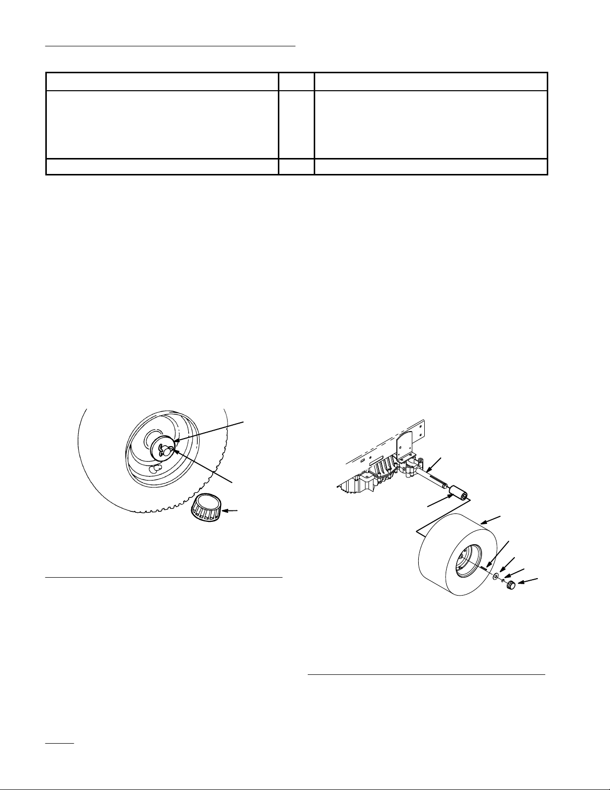
1. Grease the axle to prevent corrosion.
Check Tire Pressure (below).
2. Slide spacer then wheel, with valve stem to the
1. Install shim washers onto axle.
2. Install wheel onto axle with valve stem out.
outside, onto axle (Fig. 2).
3. Slide key into keyway of axle and wheel hub
(Fig. 2).
3. Slide the flat washer onto the axle. Insert cotter
pin through the axle and bend the ends of the pin
4. Slide shim washer(s) onto axle.
apart (Fig. 1). If cotter pin does not fit, remove
shim washer(s) as required.
5. Slide washer onto axle and secure with E-ring
(Fig. 2). If E-ring does not fit, remove shim
4. Push the hub cap (Fig. 1) onto the end of the
washer(s) as required.
axle.
6. Press hub cap over washer (Fig. 2).
1
2
3
Figure 1
1. Flat washer
2. Cotter pin
3. Hub cap
5. Repeat steps 1–4 on opposite side.
6. Grease the wheel bearings until grease comes out
of bearing seal area.
1779
1. Axle
2. Spacer
3. Wheel
4. Key
2
Figure 2
1
3
4
5
6
5. Washer
6. E-rung
7. Cap
2
Page 3
Set-Up Instructions
Check Tire Pressure
Check front and rear tires for proper inflation. Refer
to the Operator’s Manual, Maintenance Section under
Tire Pressure for recommended inflation pressure.
Install Steering Wheel
1. Move front wheels straight ahead.
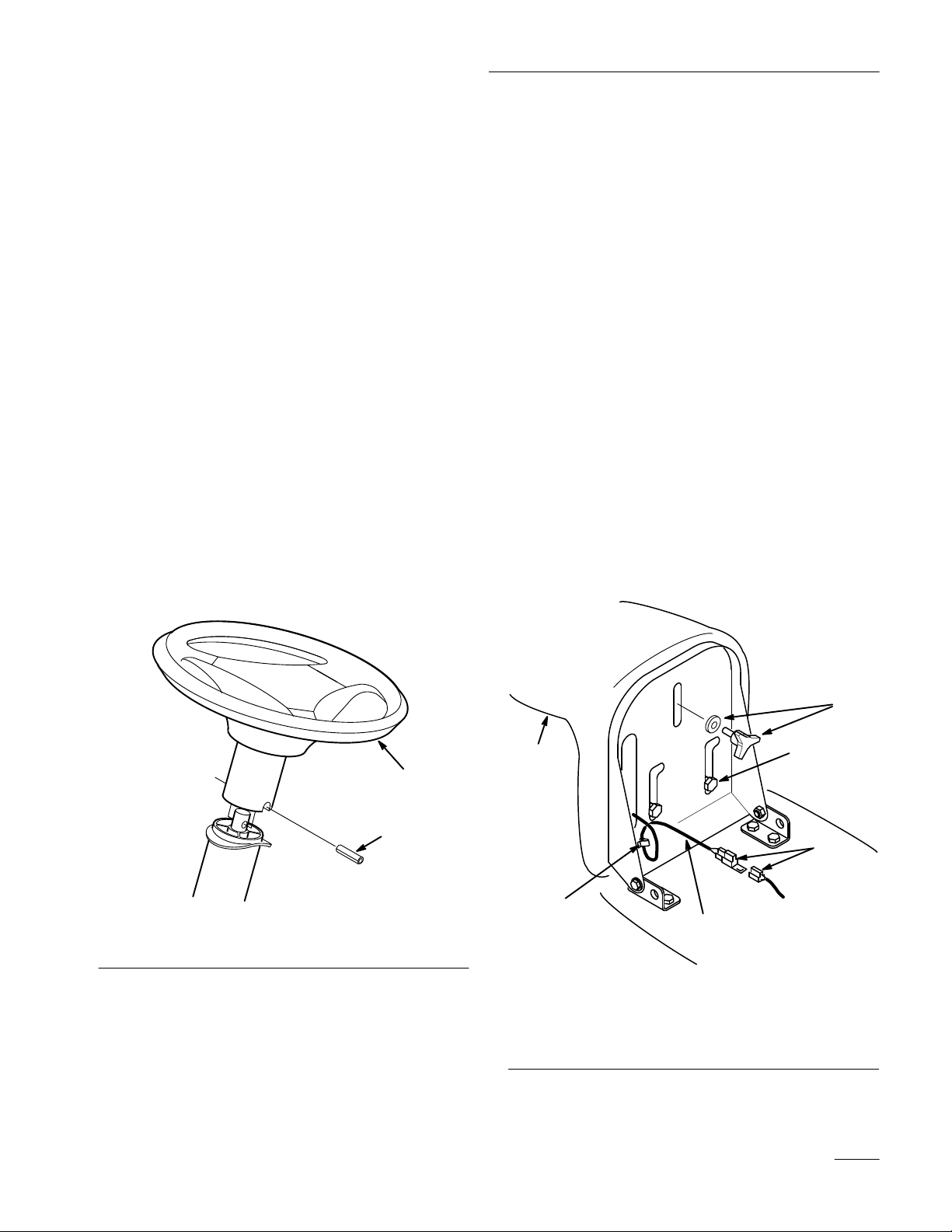
2. Slide the steering wheel over shaft. Line up the
hole in the steering wheel with the hole in the
shaft (Fig. 3). From the seat you should be able
to read the brand logo on the steering wheel.
3. To align the holes, insert a punch or long nail
partially through the holes in the steering wheel
and shaft. Then insert the spirol pin into the hole
on the opposite side.
4. Using a hammer, drive the spirol pin in until it is
flush with the outside of the steering wheel
(Fig. 3).
Install Seat
Note: If the seat is already installed, proceed
to Activate The Battery, page 4.
1. Insert seat switch wire cable through the hole in
the seat base (Fig. 4).
2. Position the seat onto the seat base by inserting
the two shoulder bolts through key hole
openings at the end of both slots (Fig. 4).
3. Thread the knob and flat washer through slot
into the rear center hole in the seat (Fig. 4).
Adjust the seat and tighten the knob.
4. Push the seat switch connector fully into the
wire harness connector (Fig. 4).
5. Secure the seat switch wire cable to seat base
with wire clip (Fig. 4).
Note: Check seat switch wire routing, it must
not be pinched in seat brackets.
Figure 3
1. Steering wheel 2. Spirol pin
4
1
2
1
5
1. Seat
2. Wire and connector
3. Shoulder bolts
2
Figure 4
4. Knob and flat washer
5. Wire clip
6. Connectors
3
6
2364
3
Page 4
Set-Up Instructions
Activate the Battery
Bulk electrolyte with 1.260 specific gravity must be
purchased from a local battery supply outlet.
1. Remove the battery and battery box from the
tractor: refer to Operator’s Manual, Removing
the Battery.
IMPORTANT: Be careful not to damage the
long vent tube when removing the battery
box.
POTENTIAL HAZARD
• Battery electrolyte contains sulfuric acid
which is a deadly poison and it causes
severe burns.
WHAT CAN HAPPEN
• If you carelessly drink electrolyte you could
die or if it gets onto your skin you will be
burned.
2
3
1
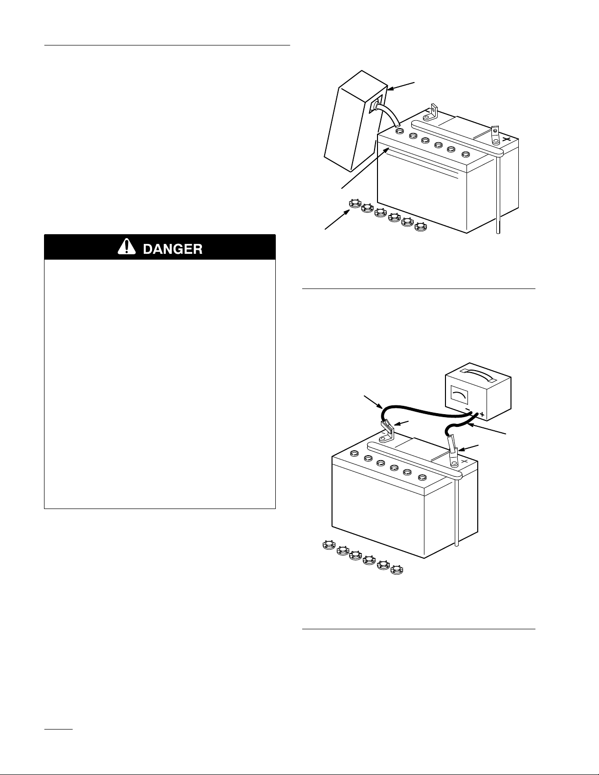
Figure 5
1. Filler caps
2. Electrolyte
3. Upper line
3. Leave the filler caps off and connect a 3 to 4
amp battery charger to the battery posts (Fig. 6).
Charge the battery at a rate of 4 amperes or less
for 4 hours (12 volts).
HOW TO AVOID THE HAZARD
• Do not drink electrolyte and avoid contact
with skin, eyes or clothing. Wear safety
glasses to shield your eyes and rubber
gloves to protect your hands.
• Fill the battery where clean water is always
available for flushing the skin.
• Follow all instructions and comply with all
safety messages on the electrolyte container.
2. Unscrew six filler caps from the battery. Slowly
pour electrolyte into each cell until the level is
up to the “UPPER” line on the battery case
(Fig. 5).
1. Positive post
2. Negative post
4
2
3
1
Figure 6
3. Charger red (+) wire
4. Charger black (–) wire
4
Page 5

Set-Up Instructions
Fill Crankcase with Oil
POTENTIAL HAZARD
• Charging battery produces gasses.
WHAT CAN HAPPEN
• Battery gasses can explode.
HOW TO AVOID THE HAZARD
• Keep cigarettes, sparks and flames away
from battery.
4. When the battery is fully charged, disconnect the
charger from the electrical outlet and from the
negative and positive battery posts (Fig. 6).
5. Slowly pour electrolyte into each cell until the
level is once again up to the “UPPER” line on
the battery case (Fig. 5).
6. Install the battery and battery box in the tractor:
refer to the Operator’s Manual, Installing the
Battery.
The tractor is shipped from the factory without oil in
the engine crankcase: refer to the Operator’s Manual,
Engine Oil Specifications for oil type, viscosity, and
crankcase capacity. Only add about 80% of the
specified amount of oil. Then check the oil level and
add only enough oil to raise the level to the “FULL”
mark on the dipstick.
Lubricate the Tractor
Refer to the Operator’s Manual, Greasing and
Lubrication.
Insert Keys into Ignition and
“Key Choice” Switches
The “Key Choice” switch is located on the seat
bracket in front of and below the seat. Refer to
Operator’s Manual, Operation Section.
Check Safety System
Refer to the Operator’s Manual, Checking Safety
System.
5
Page 6
Set-Up Instructions
Purge Hydro Transaxle
During handling and shipping air can be introduced
into the hydro transaxle. To achieve proper
performance all trapped air must be removed.
1. Place tractor on a flat level surface.
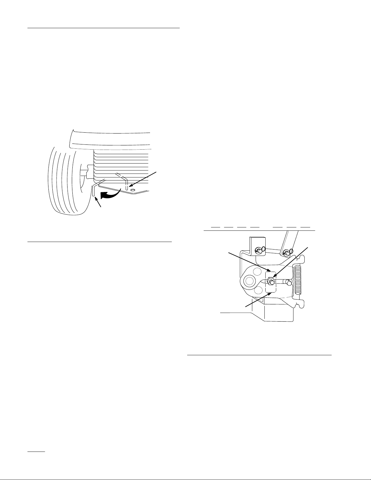
2. Place the drive control, under rear frame. to the
“Push” position (Fig. 7).
1
2
Figure 7
1. Operate position 2. Push position
1791
Check Hydro Neutral Position
Adjustment is required if the tractor creeps without
the traction control pedal being depressed.
1. Run engine at a low idle and move traction
control pedal forward, then release. Move
traction control pedal reverse, then release. If the
tractor creeps adjust as follows:
2. Raise the rear wheels off the ground and support
with jackstands.
3. Loosen locknut securing adjustment (Fig. 8).
4. Move adjustment stud up or down until creep is
minimized (Fig. 8). There may still be some
wheel rotation with wheels off the ground.
5. Tighten the locknut (Fig. 8). Move the traction
control pedal forward and reverse and allow it to
center. Verify that there is no creep with the
wheels on the ground.
3. Run engine at a low idle and move traction
control pedal forward for five (5) seconds then
reverse for five (5) seconds. Repeat three (3)
times.
4. Place the drive control in the “Operate” position
(Fig. 7). Drive the tractor forward then reverse
approximately five (5) feet. Repeat three (3)
times.
1
2
2
1673
Figure 8
1. Locknut
2. Stop
6
Page 7
Set-Up Instructions
Check Traction Control Pedal
After adjusting the hydro neutral position it is
necessary to check the traction control pedal travel.
While pressing the control pedal full forward and full
reverse it must not contact the footrest pad before
hitting the stop(s) at the transaxle (Fig. 8).
1. If contact is made with the foot pad, before
hitting stop(s) on transaxle (Fig. 8), in either
forward or reverse directions, adjustment is
required.
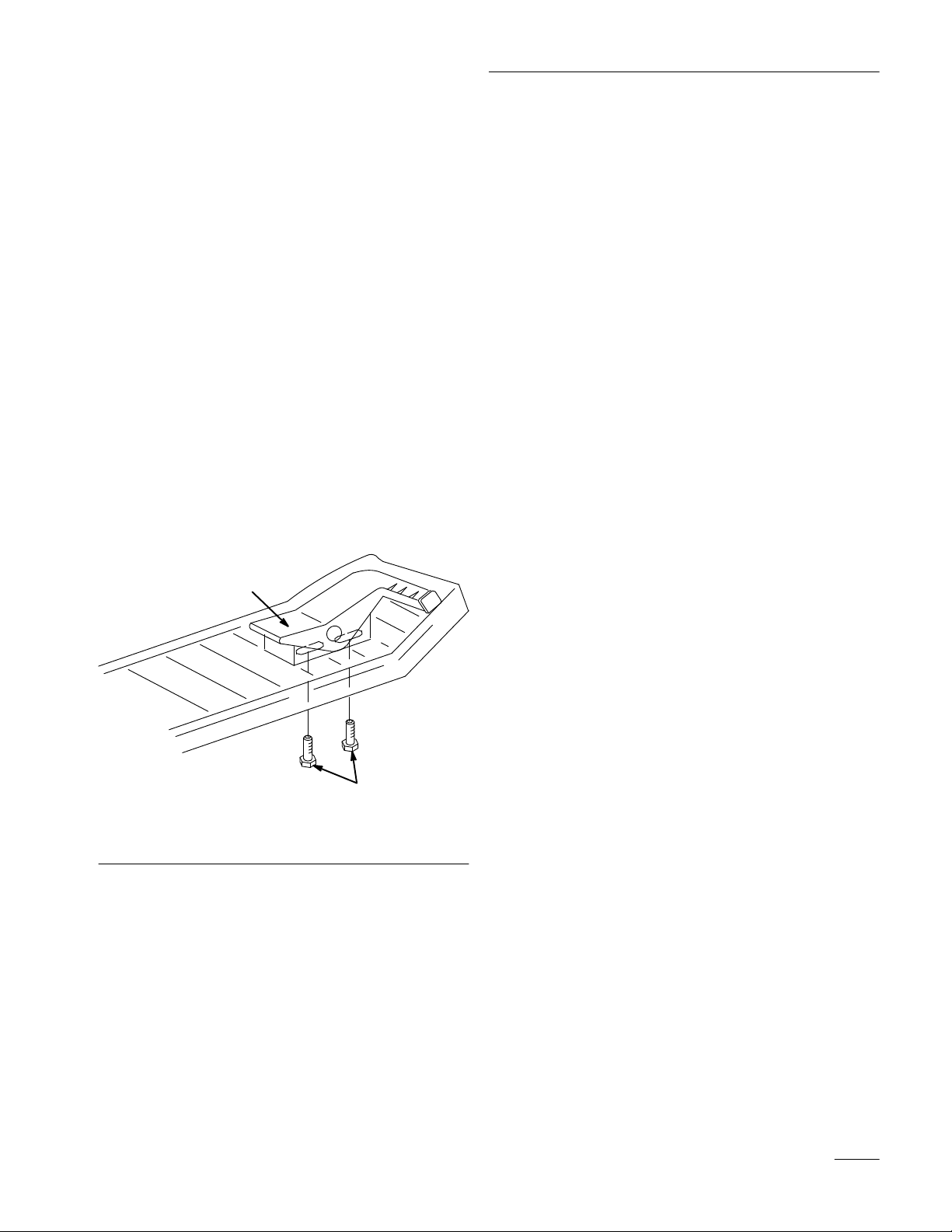
2. Loosen the capscrews below the right footrest.
Slide the pedal in the slots away from the
direction that made contact with the footrest
(Fig. 9).
3. Tighten capscrews and recheck traction control
pedal for contact with stop(s) on transaxle and
footrest.
Test Drive the Tractor
Make sure all electrical and mechanical systems are
operating properly.
1
2
Figure 9
1. Traction control pedal 2. Adjusting capscrews
7
Page 8

 Loading...