

Page 1

HYDRO-GEAR 310-0500/0750 SERVICE MANUAL
Table of Contents – Page 1 of 1
INTRODUCTION/GENERAL DESCRIPT ION
INTRODUCTION
GENERAL DESCRIPTION
MAINTENCE
FLUIDS/GREASES
SAFETY PRECAUTIO NS
MAINTENANCE
TROUBLESHOOTING DIAGRAM 310-500/0750 IHT
TROUBLESHOOTING DIAGRAM
MINOR REPAIRS
GENERAL INFORMATION
SHAFT SEALS
PARKING BRAKE
CONTROL ARM & FRICTION PACK
OIL LEVEL
MAJOR REPAIRS
GENERAL INFORMATION
DISASSEMBLY PRO CED URE S
DISASSEMBLY PRO CED URE S
DISASSEMBLY PRO CED URE S
DISASSEMBLY PRO CED URE S
DISASSEMBLY PRO CEDURES
RECONDITIONING AND REPLACEMENT OF PARTS
ASSEMBLY PROCEDURES
ASSEMBLY PROCEDURES
ASSEMBLY PROCEDURES
ASSEMBLY PROCEDURES
ASSEMBLY PROCEDURES
ASSEMBLY PROCEDURES
OIL FILL & START-UP PROCEDURES
310-0500 PARTS DRAWING & PARTS LIST
310-500/0750 IHT PARTS DRAWING & PARTS LIST
PARTS DRAWING & PARTS LIST 310-0500/0750 IHT
PARTS DRAWING & PARTS LIST 310-500/0750 IHT
PRODUCT LINE - HYDRO-GEAR
A WORLD LEADER IN TURF CARE TRANSMISSION PRODUCTS
Page 2
Page 3
Table
of
Contents
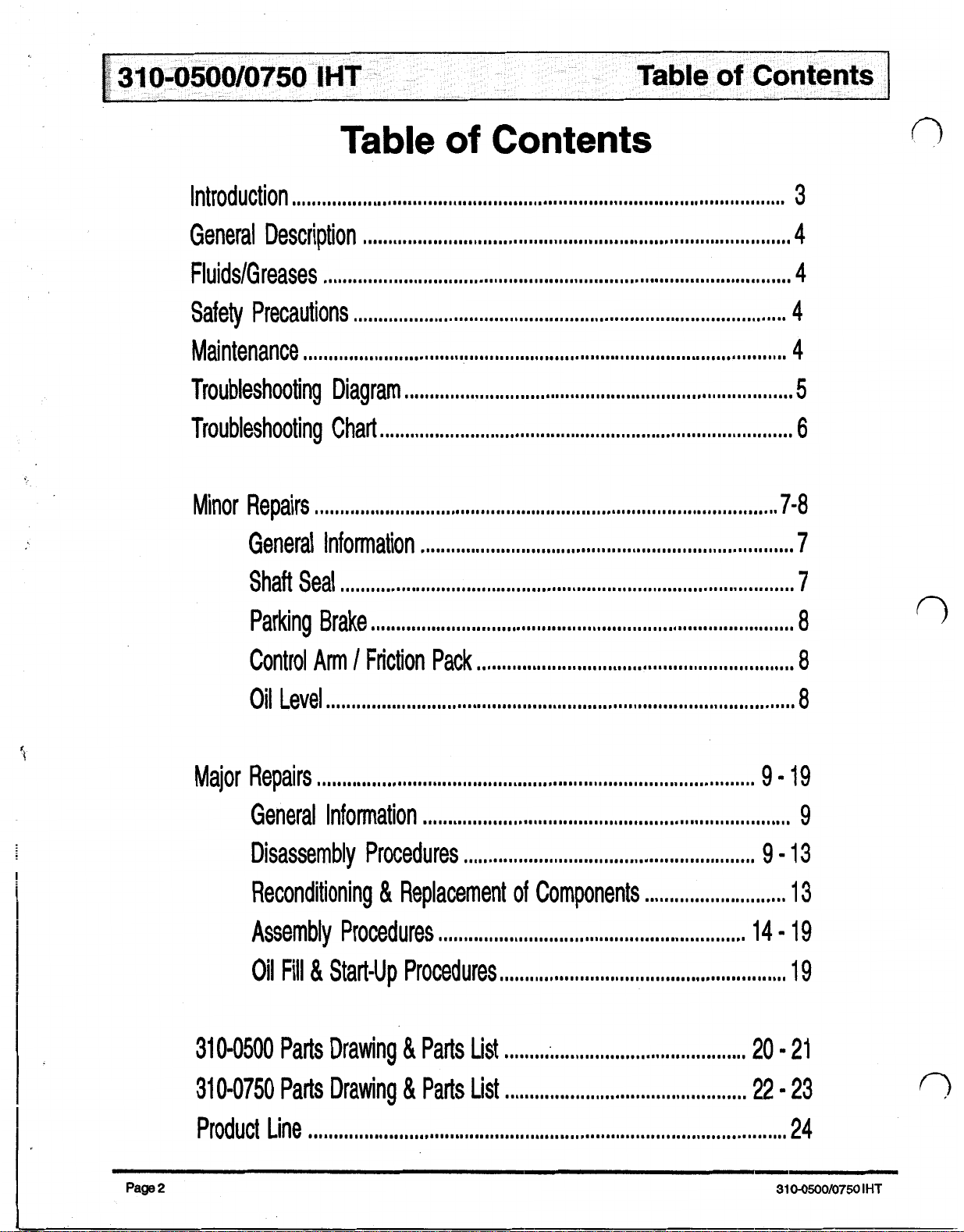
Introduction
General Description
FIuids/Greases
Safety Precautions
Maintenance
Troubleshooting Diagram
Troubleshooting Chart
Minor Repairs
..................................................................................................
.....................................................................................
.............................................................................................
......................................................................................
................................................................................................
.............................................................................
..................................................................................
............................................................................................
General Information
Shaft Seal
Parking Brake
..........................................................................................
....................................................................................
..........................................................................
3
4
4
4
4
5
6
7-8
7
7
8
Control
Oil Level
Major Repairs
General Information
Disassembly Procedures
Reconditioning
Assembly Procedures
Oil Fill & Start-up Procedures
310-0500
310-0750
Arm
/
.............................................................................................
.......................................................................................
Parts Drawing
Parts Drawing
Friction Pack
...............................................................
.........................................................................
..........................................................
&
Replacement
of
.............................................................
.........................................................
&
Parts List
&
Parts List
................................................
................................................
Components
............................
8
8
9-19
9
9-13
13
I4 - 19
19
20 - 21
22-23
Page
Product Line
2
...............................................................................................
24
310-0500/07501HT
Page 4
Introduction
The purpose
useful in servicing the Hydro-Gear Integrated Hydrostatic Transaxle (IHT). This manual includes component
description, troubleshooting, maintenance and repair
procedures.
A
transaxle normally
life of the vehicle in which it
be
required, the unit must be removed from its installed
location and thoroughly cleaned before beginning
procedures.
of
this manual is to provide information
will
not require servicing during the
is
installed. Should servicing
most
General Description
The Integrated Hydrostatic Transaxle is a
unit designed for the transfer and control of power.
provides an infinitely variable
and maximum in both forward and reverse modes of
operation.
The IHT uses a variable pump with a maximum displace-
ment of 1Occ per revolution, and a motor with a fixed
displacement of 21cc per revolution. The variable
placement pump features a cradle swashplate with a
direct-proportional displacement control. Reversing the
direction of tilt of the swashplate reverses the flow of oil
from the pump to the motor and thus reverses the
direction of the motor output rotation. The fixed displacement motor uses a
motor are of the axial piston design, and both utilize
spherical nosed pistons which are held against a thrust
race by internal compression springs.
fixed
speed
swashplate. The pump and
self
contained
range between zero
dis-
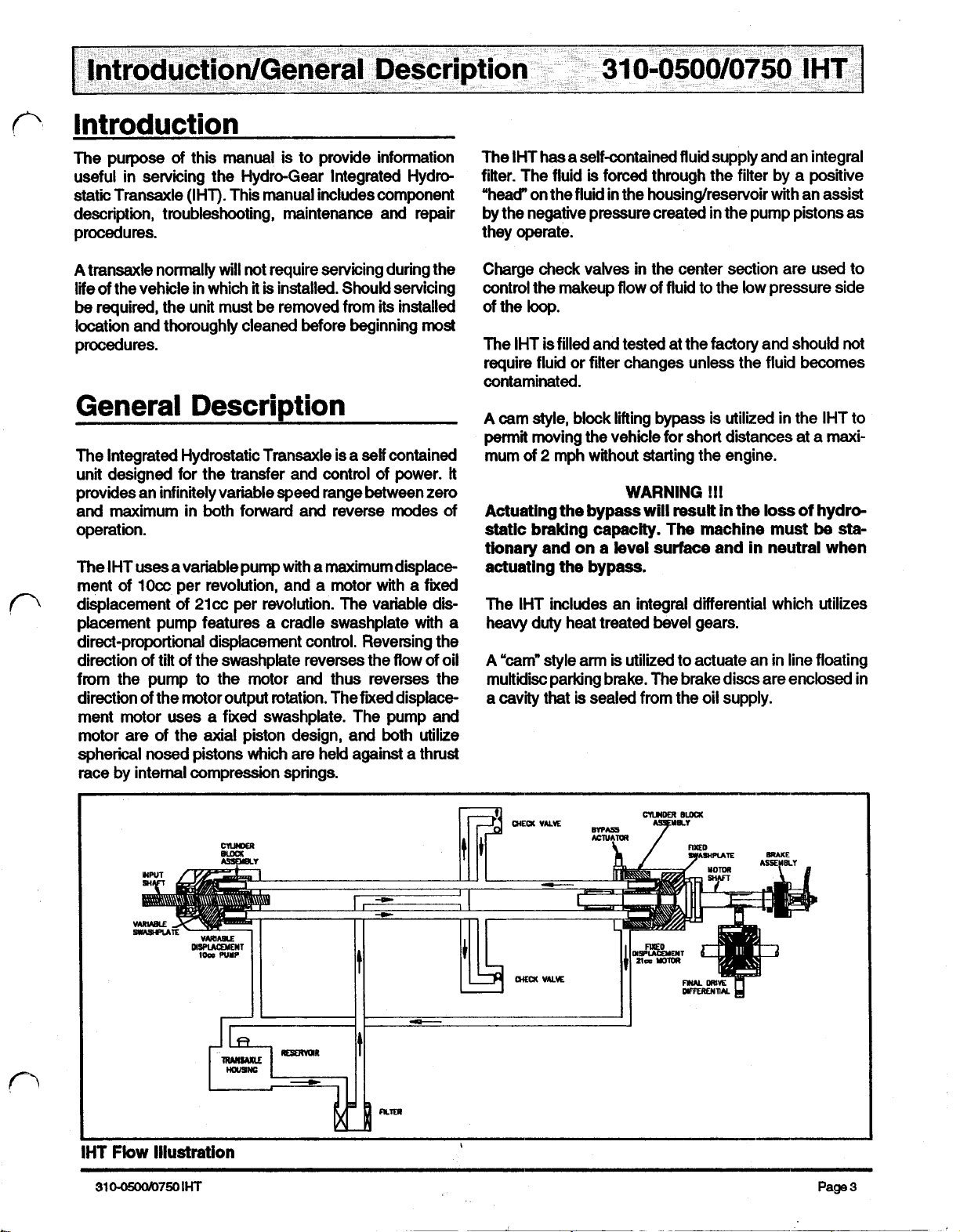
The IHT has a self-contained fluid supply and an integral
filter. The fluid
"head" on the fluid in the housing/reservoir with an assist
by the negative pressure created in the pump pistons
they operate.
Charge check valves in the center section are used to
control the makeup flow of fluid to the low pressure side
of the
loop.
The IHT is filled and tested at the factory and should
require fluid or filter changes unless the fluid becomes
contaminated.
A
cam style, block
permit moving the vehicle for short distances at a maxi-
mum of 2 mph without starting the engine.
It
Actuating the bypass
static braking capacity.
tionary and on a level surface and in neutral when
actuating the bypass.
The IHT includes an integral differential which utilizes
heavy duty heat treated bevel gears.
A
"cam" style arm is utilized to actuate an in line floating
multidisc parking brake. The brake discs are enclosed in
a cavity that
is
forced through the filter by a positive
lifting
bypass
WARNING
will
is
sealed from the oil supply.
is
utilized in the IHT to
!!!
result in the
The
machine must
loss
of
as
not
hydro-
be
sta-
IHT
Flow
310-0500/0750
Illustration
IHT
Page
3
Page 5
Fluids/Greases
The fluids used in HYDRO-GEAR products have been
carefully selected, and only equivalent or better products
be
should
used.
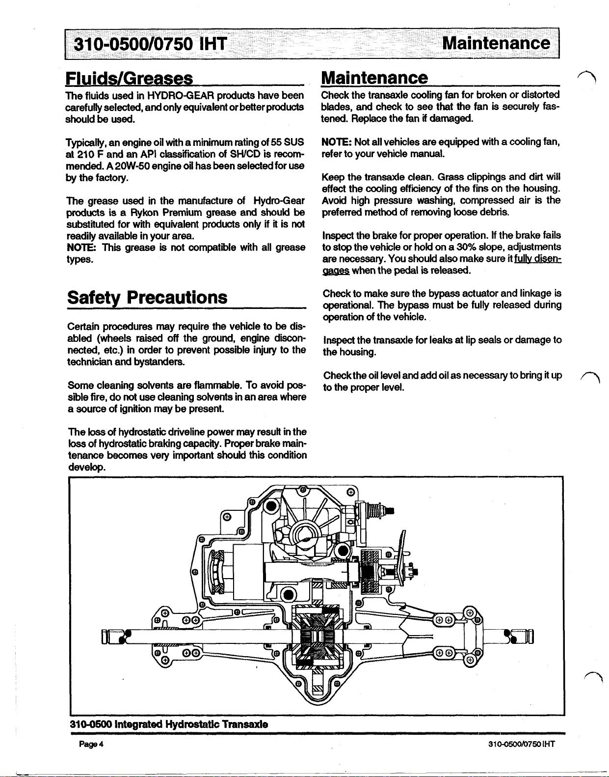
Maintenance
Check the transaxle cooling fan for broken or distorted
blades,
tened. Replace the
and
check to
fan
see
that the fan
if
damaged.
is
securely fas-
Typically, an engine oil with a minimum rating of
at
210
F
and an
mended. A
by the factory.
The grease used in the manufacture of Hydro-Gear
products
substituted for with equivalent products only
readily available in your area.
NOTE:
types.
is a Rykon Premium grease
This grease
API
2OW-50
classification
engine oil has been selected for
of
SWCD is recom-
and
is
not compatible with all grease
55
SUS
use
should
if
it is
not
be
Safety Precautions
Certain procedures may require the vehicle to
abled
technician
(wheels
nected, etc.) in order to prevent possible injury to the
Some cleaning solvents are flammable.
sible fire, do not use cleaning solvents in an area where
a source of ignition may be present.
raised off the ground, engine discon-
and
bystanders.
To
be
avoid
dis-
pos-
NOTE:
refer
Keep
effect the cooling efficiency of the fins on the housing.
Avoid high pressure washing, compressed air is the
preferred method
Inspect
to stop the vehicle or hold on a
are necessary. You should also make sure it
gages
Check to make sure the bypass actuator and linkage
operational. The bypass must be fully released during
operation of the vehicle.
Inspect
the housing.
Check the oil level and add oil as necessary to bring it up
to the proper level.
Not all vehicles are equipped with a cooling fan,
to
your vehicle manual.
the transaxle clean. Grass clippings and dirt will
of
removing loose debris.
the brake for proper operation.
30%
when the
the transaxle for leaks at lip seals or damage to
pedal
is
released.
If
the brake fails
slope, adjustments
fully
disen-
is
loss
The
loss
tenance
develop.
of hydrostatic driveline power may result in the
of hydrostatic braking capacity. Proper brake main-
becomes
very important should
this
condition
310-0500
Page
4
Integrated
Hydrostatic
Transaxle
310-0500/0750
IHT
Page 6
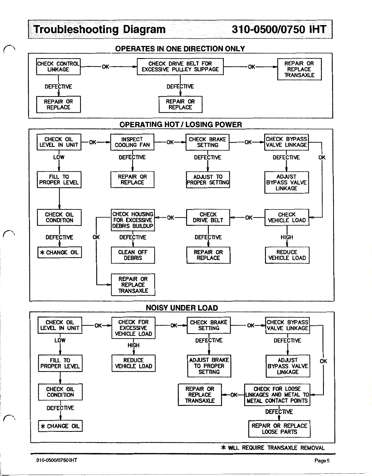
OPERATES
IN
ONE DIRECTION ONLY
CHECK CONTROL OK CHECK DRIVE BELT
LINKAGE EXCESSIVE PULLEY SLIPPAGE REPLACE
I
DEFECTIVE
LOW
PROPER LEVEL
CONDITION
DEFECTIVE DEFECTIVE DEFECTIVE HIGH
FOR
OK
REPAIR OR
I
I
DEFECTIVE
REPLACE
OPERATING
DEFECTIVE
FOR
EXCESSIVE DRIVE BELT VEHICLE LOAD
DEBRIS BUILDUP
IG
HOT/ LOSING POWER
DEFECTIVE
I
PROPER SETTING
LINKAGE
*
CHANGE OIL
LEVEL
FILL TO
DEFECTIVE
DEBRIS REPLACE
REPLACE
TRANSAXLE
NOISY
IN UNIT VALVE LINKAGE
VEHICLE LOAD
HIGH
VEHICLE LOAD
I
I
VEHICLE LOAD
UNDER LOAD
DEFECTIVE DEFECTIVE
I
TO PROPER
TRANSAXLE REPAIR
OR
LINKAGES AND METAL TO
METAL
BYPASS VALVE
CONTACT POINTS
I
ADJUST
LINKAGE
I
If
*
REWIRE TRANSAXLE REMOVAL
Page
5
Page 7
THE ENGINE DISABLED BEFORE PERFORMING ANY ADJUSTMENTS
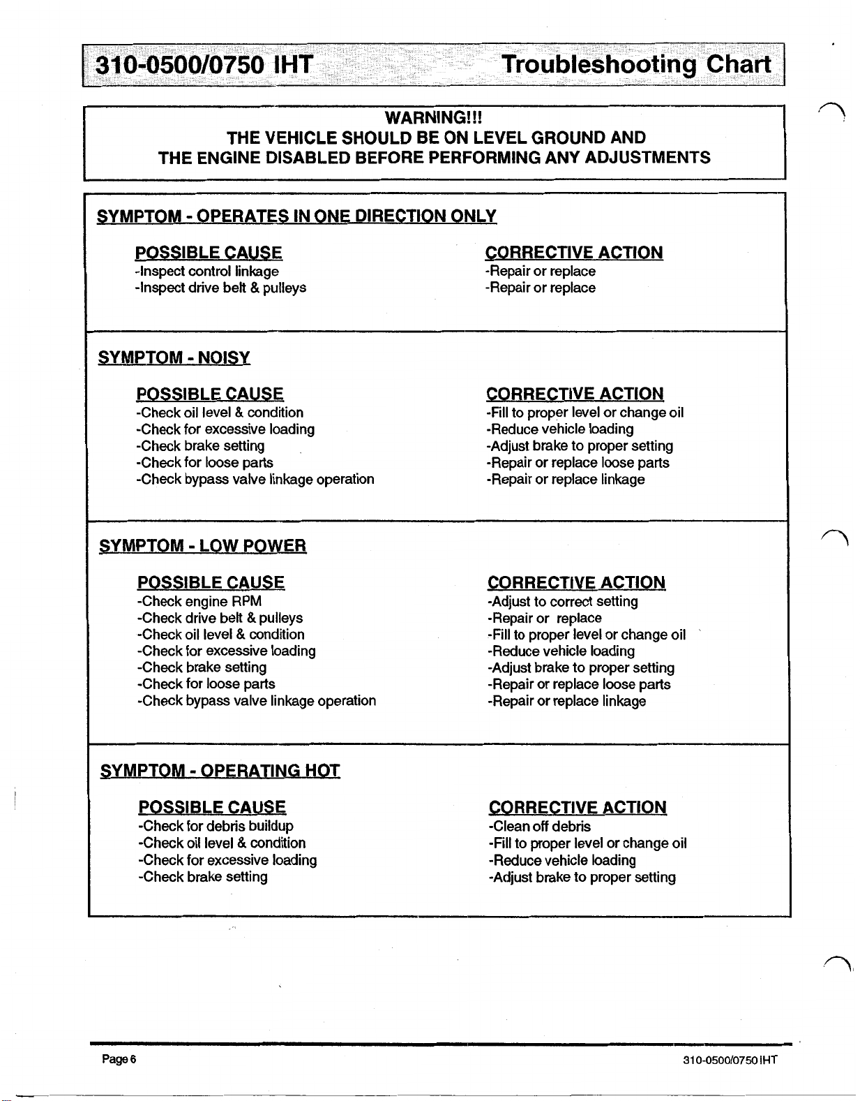
SYMPTOM
WARNING!!!
THE VEHICLE SHOULD BE ON LEVEL GROUND AND
-
OPERATES
IN
ONE DIRECTION ONLY
POSSIBLE CAUSE
-Inspect control linkage
&
-Inspect drive belt
pulleys
SYMPTOM - NOISY
POSSIBLE CAUSE
-Check oil level & condition
-Check for excessive loading
-Check brake setting
-Check for loose parts
-Check bypass valve linkage operation
SYMPTOM - LOW POWER
POSSIBLE CAUSE
-Check engine
-Check drive belt & pulleys
-Check oil level
-Check for excessive loading
-Check brake setting
-Check for loose parts
-Check bypass valve linkage operation
RPM
&
condition
CORRECTIVE ACTION
-Repair or replace
-Repair or replace
CORRECTIVE ACTION
-Fill
to proper level or change oil
-Reduce vehicle loading
-Adjust brake to proper setting
-Repair or replace loose parts
-Repair or replace linkage
CORRECTIVE ACTION
-Adjust to correct setting
-Repair or replace
-Fill to proper level or change oil
-Reduce vehicle loading
-Adjust brake to proper setting
-Repair or replace loose parts
-Repair or replace linkage
SYMPTOM - OPERATING HOT
POSSIBLE CAUSE
-Check for debris buildup
-Check oil level
-Check for excessive loading
-Check brake setting
Page
6
&
condition
CORRECTIVE ACTION
-Clean
-Fill to proper level or change oil
-Reduce vehicle loading
-Adjust brake to proper setting
off
debris
31
0-0500/0750
IHT
Page 8
Minor Repairs
General Information
Minor Repairs may
dures in this section, without voiding the unit warranty.
Cleanliness is a primary means of assuring satisfactory
life of either new or repaired units. Cleaning parts by
using solvent wash and air drying is usually adequate.
with any precision equipment,
of foreign materials and chemicals.
Protect all exposed sealing surfaces and open cavities
from damage and foreign material. The outer surfaces
the transaxle should be cleaned before beginning any
repairs.
be
performed, following the proce-
all
parts must
be
kept free
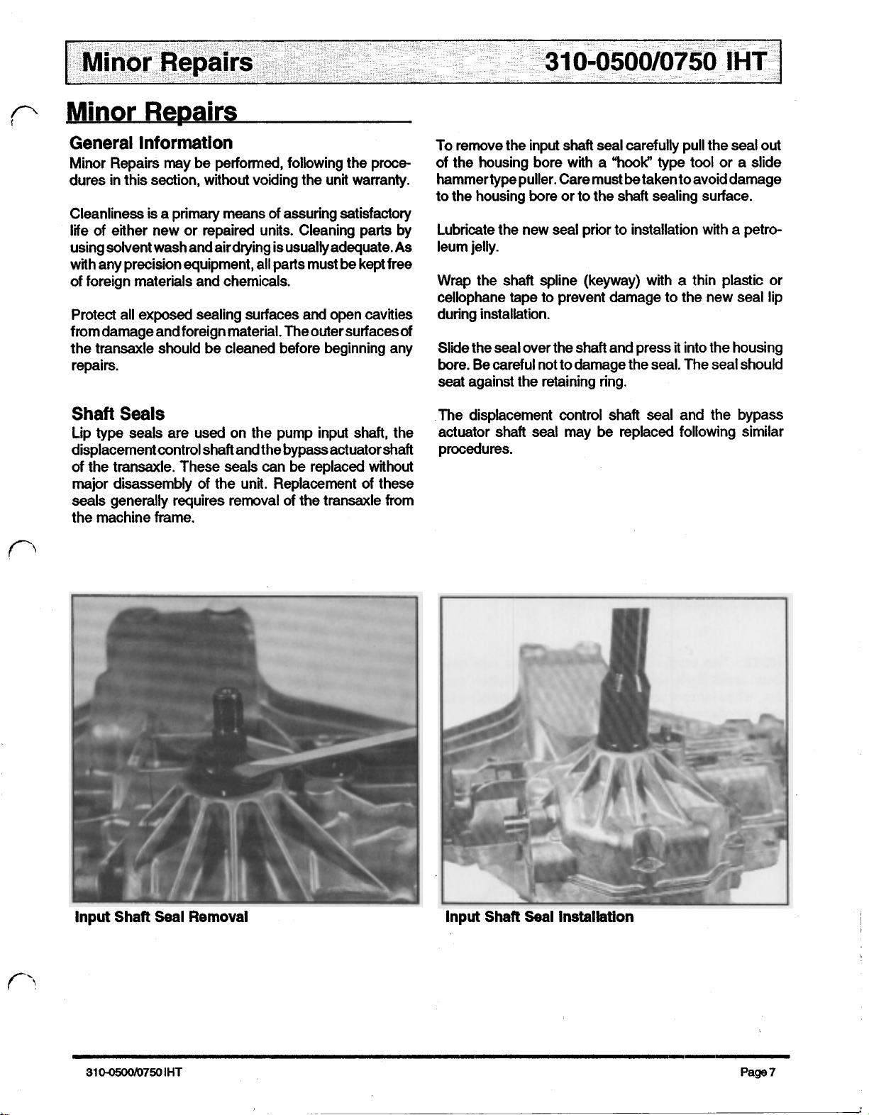
To remove the input shaft seal carefully pull the seal
of the housing bore with a “hook” type tool or a slide
hammertype puller. Care must
to the housing bore or to the shaft sealing surface.
Lubricate the new seal prior to installation with a petro-
As
leum jelly.
Wrap
cellophane tape to prevent damage to the new seal lip
during installation.
of
Slide the seal over the shaft and press
bore. Be careful not to damage the seal. The seal should
seat against the retaining ring.
be
taken to avoid damage
the shaft spline (keyway) with a thin plastic or
it
into the housing
out
Shaft
Lip type seals are used on the pump input shaft, the
displacement control shaft and the bypass actuator shaft
of the transaxle. These seals can be replaced without
major disassembly
seals generally requires removal of the transaxle from
the machine frame.
Seals
of
the unit. Replacement of these
The
actuator shaft seal may be replaced following similar
procedures.
displacement control shaft seal and the bypass
Input
Shaft
3100500/7501HT
Seal
Removal
Input
Shaft
Seal
Installation
Page?
Page 9

Parking
Brake
The brake was set at a specific running clearance
(approximately 0.030") between the discs to the Original
Equipment Manufacturers specifications. Refer to the
vehicle service manual for the correct clearance.
Place a feeler gage between the
is
clearance
not correct make the necessary change with
outer discs,
if
the
two
the brake retainer nut.
Control Arm & Friction Pack
NOTE:
models and is not used on some. The
established individual specifications for the proper adjustments. Refer to vehicle service manual for the proper
procedures.
Friction Pack Variations
Oil
To check the oil level you must first remove the breather
fitting from the housing.
The control arm and friction pack vary between
OEM
have
NON-ADJUSTABLE
“OLD”
FRICTION
ADJUSTABLE
I
“NEW”
FRICTION
Level
NOTE:
been used.
Two versions of the brake retainer nuts have
Early
production employed a "Nylock"
nut, while current production is using a castellated
with a cotter pin for retainment.
50316
5004
type
nut
NOTE:
Make sure the surrounding area has been thoroughly cleaned prior to removal of the fitting to prevent
the introduction of contamination into the oil.
The
oil level should be between 1.75" and
top of the housing for the 310-0500, and between
and 1.62" from the top of the housing for the 31
2.0"
from the
1.25"
0-0750.
NEW STYLE
Brake Retainer
Page
8
Nut
Variatlons
OLD
STYLE
31
Oil
Levels
310-0750
310-0500/0750
IHT
Page 10

General
Major Repairs described in the following sections are for
the complete disassembly and reassembly (Major
pair) of the IHT and will void all product warranty, unless
license to
obtained from an Authorized Representative of Hydro-
Gear.
Cleanliness is a primary means of assuring satisfactory
life on new or repaired units. Cleaning parts by using a
solvent wash and air drying
any precision equipment, all parts must
foreign materials and chemicals.
Protect all exposed sealing surfaces and open cavities
from damage and foreign material. The outer surfaces
should
It
is recommended that all seals be replaced. Lightly
lubricate all seals with a clean petroleum jelly prior to
assembly.
It
is recommended that parts requiring replacement
replaced as a complete assembly
service parts drawings on pages
Prior to perfomring Major Repairson the IHT, remove the
transaxle from its installed location and remove any
external components such as the brake arm, brake
actuating pins, control arm (and friction pack
cooling fan and input pulley or frame mounting hardware.
NOTE:
any further disassembly.
Information
Re-
perform
be
cleaned before beginning any repairs.
Thoroughly clean all exposed surfaces prior to
said Major Repair was previously
is
usually adequate. As with
be
kept
free
(kit)
as
shown
20 -23.
if
included),
in the
Position and secure the IHT with the upper housing down
to allow access to the twenty housing assembly cap
screws.
of
Remove
be
Using the appropriate tool, remove the twenty assembly
screws.
internal hex head cap screw was used, at that time a
change was made to an
screw.
Loosen the nut on the brake arm mounting bolt.
Separate the two housing halves by applying pressure
(as shown) with two large straight blade screw drivers.
Use caution to prevent damage to the mating sealing
surfaces as you separate the
sealant
Housing
NOTE:
will
make the
Assembly
Prior to October
Bolts
"E-8"
external drive
two
two
halves difficult to separate.
27, 1993
halves.
a
3/16"
“Torx”
NOTE:
drive
cap
The
Disassembly
Drain the
positioning the IHT
allow the oil to drain thoroughly.
Drain Oil
310-0500/07501HT
oil
From
Procedures
by removing the breather assembly and
so
that the breather port
Breather
Port
is
down to
Separate
Housing
Halves
Page
9
Page 11

Disassembly
All
components should remain in the upper housing
(positioned
Procedures
down).
NOTE:
sembly.
The lip
seals
must not be reused during reas-
CAUTION: The axle/differential
as
the
lower housing is being
assembly
lifted
off
may
of
the upper
stick
housing.
Inspect the lower housing for damage.
journal bearing pockets for excessive wear. Inspect the
brake rotor/stator pocket for excessive wear.
NOTE:
thoroughly cleaned and
Prior to reassembly the lower housing must
old
sealant must be removed.
Inspect
the axle
be
Inspect
bearings should
Inspect
axle
Inspect
ends.
Inspect
damage.
Check the differential assembly screws for proper torque.
For the
while the 310-0750 should
Inspect
ing for excessive wear by feeling the shafts for an
unreasonable amount of play.
If excessive wear or damage has been found, the com-
plete assembly must be replaced.
the bronze bearings for excessive wear. The
be
0.7535”
the axle ends for damage or excessive wear. The
ends should
the differential bevel gears by rotating the axle
the final drive gear teeth for excessive wear
31
0-0500
the journal bearings inside the differential hous-
be
0.7486' to 0.7496".
they should be torqued to 16-1
to
0.7561'
be
torqued to
I.D..
12-14
8
ft.lbs.
ft.lbs..
or
31
0-0750
Lift
ing.
rust from the axle ends prior to the removal of the
bronze bearings or damage to the bearings
Remove the two bronze journal bearings, four lip
and
Components In Upper Housing
the axle/differential assembly
NOTE:
two
It
will
be
necessary to remove any burrs or
flat washers from the axle ends.
out
of the upper
hous-
will
occur.
seals
two
31
0-0750
Axle / Differential Components
Remove
Page
10
Axle
/
Differential Assembly
Page 12

Disassembly Procedures
Remove the brake rotors and stators by sliding one at
time
off
of the end of the splined motor shaft.
of
Removal and Inspection
Brake Rotors
Inspect each side of both rotors for excessive wear or
damage.
a
Using a
9/16”
socket (or box end) wrench, remove the
three assembly bolts retaining the center section in the
upper housing.
CAUTION: The pump and motor piston springs may
push the center section assembly
while you remove these
bolts.
out
of
position
Remove Center Section Assembly
Inspect the rotors internal splines for excessive wear or
damage.
Remove the center section assembly from the housing.
The pump block assembly should remain in the upper
housing on the input shaft, but may stick to the center
Inspect the stators for excessive wear and damage.
section. Check the check valve plate
not remove. Two styles of check plates have been used,
one
Replace rotors and stators as a complete
wear or damage is found, and inspect
kit
if
all
other mating
parts.
excessive
has three bolts while the other has four. The one with
four bolts should be torqued from
the one with three
185
in. Ibs..
Remove the oil filter. After inspecting the filter for unusual
particles that
it
may have trapped, dispose of
it
properly
and replace it with a new oil filter during reassembly.
CAUTION: The aligning pins, motor shaft, bypass
plate, pump
NOT retained to the center section or the upper
housing and may become separated from the as-
sembly during removal.
bolt
torque, but do
170
to
240
bolts
should be torqued from
block
and motor block assemblies are
in.lbs. while
135
to
Remove
Oil
Filter
Center Section
/
Motor Shaft
Page
1 1
Page 13

Disassembly
Remove the motor block assembly from the motor shaft
and inspect for unusual wear or damage. The pistons
should fit with very little side clearance in the block bores,
but must slide freely.
for the block
Procedures
For
hex head cap screws retaining the jack shaft to the
housing with a 5mm hex wrench and remove the jack
shaft
NOTE:
is
0.6776 to 0.6784 and the pistons should be
The correct bore diameter
310-0750
/
pinion gear assembly from the housing.
0.6767 to 0.6770.
Remove the motor shaft, washers and bypass plate from
the center section and inspect for unusual wear or
damage.
Inspect the center section running surfaces for unusal
wear or damage.
Remove the pump block assembly, block thrust washer
and spring from the input shaft and inspect for unusual
fit
wear or damage. The pistons should
clearance in the blockbores, but must slide freely
with very little side
NOTE:
The correct bore diameter for the block is 0.6295 to
0.6303
and the pistons should be 0.6288 to 0.6291.
Remove Jack Shaft / Pinion Gear Assembly
Inspect the jackshaft running surface for excessive wear
or damage. The jack shaft should be 0.4986
0.4996
“.
Models
Only:
Remove the
two
internal
"
to
Remove Pump Block Assembly
Inspect the pinion gear bore for excessive wear or
damage. The bore should be 0.501 4
"
to
0.5024
“.
Inspect the pinion gear teeth for excessive wear or
damage.
If excessive wear or damage was found, the complete
assembly should be replaced.
Page
12
Jack Shaft / Pinion Gear Components
31
0-0500/0750
IHT
Page 14

Disassembly
Remove the motor thrust bearing assembly, swashplate
kit
and cradle bearings from the housing and inspect for
unusual wear or damage.
Procedures
Remove the pump input shaft assembly from the
housing.
Inspect the shaft and bearing for unusual wear or
damage.
Swashplate Kit and
Remove the slot guide block from the displacement
control
Remove the bypass actuator from the housing.
Reposition the housing and remove the input shaft lip
seal from the housing bore.
to pry the seal out. Care must be taken to avoid damage
to the housing bore, shaft sealing surface
Once removed, the seal is not be reusable.
shaft.
Thrust
A
Bearing Assembly
hook
type
tool may be used
or
bearing.
Pump Input Shaft Assembly
Reposition housing and remove thedisplacement control
shaft
Inspect the housing for damage.
Reconditioning and Replacement
All
solvent.
housing halves prior to reassembly
Inspect
patterns. Replace all parts having unusual, excessive
wear or discoloration.
Inspect the sealing surfaces, bearing surfaces, and shaft
splines. Polish the sealing areas on the shafts
sary. Replace any worn or damaged parts.
The running surfaces of the cylinder blocks MUST be flat
and free from scratches.
on
section, polish or replace the parts. When polishing these
surfaces, up to 0.0004 in. may be removed.
Remove Input Shaft Lip Seal
sufficient to obtain a flat surface free of scratches, the
part should be replaced.
and lip seal.
of
Parts
parts should be thoroughly cleaned in a suitable
All
sealant material MUST be removed from the
all parts for damage, nicks or unusual wear
if
neces-
If
scratches or wear are found
the running surface of the cylinder block or center
If
this is not
Remove the
input
shaft
bearing retaining ring.
Clean and lightly oil
parts
prior
to assembly
of
the
Page
IHT.
1
3
Page 15

Assembly
Procedures
Be sure to toque all threaded parts to the recommended
toque levels.
Reposition the upper housing and install the cradle
bearings.
Replace
all
O-rings
and
shaft
seals. Install the slot guide block onto the displacement control
CAUTION: Most parts have critical high tolerance
be
surfaces. Care must
to
these surfaces during assembly. Protect exposed
exercised to prevent damage
surfaces, openings and ports from damage or foreign material.
Install the displacement control shaft.
shaft.
Install the swashplate assembly into the housing. The
slot on the swashplate must engage the slot guide block
on
the
displacement control shaft. Use a tool such as a
screwdriver to hold the guide block in position while
installing the swashplate.
Install Displacement Control Shaft Swashplate Installation
Install the pump input shaft assembly and retaining ring
into the housing.
Install Pump Shaft Assembly
Install the thrust washer and and pump block spring onto
the pump shaft.
NOTE:
To
simplify the installation
of
the pump block,
wrap a rubber band snugly around the pistons. This is
intended to hold the pistons in their bores as the block kit
is handled during installation.
Install the pump shaft lip
Page
1
4
seal.
Cylinder Block Kit with Rubber Band
31
0-0500/0750
IHT
Page 16

Assembly Procedures
With the swashplate in the neutral
lubricate the running surfaces and install the block
(0
angle) position,
Install the aligning pins and the bypass actuator into the
housing.
kit
onto the pump input shaft. Make sure the splines engage
properly.
Install Aligning Pins and Bypass Actuator
Install the washers and a new lip seal onto the motor
shaft.
Install Pump
Block
Kit
Install the motor shaft into the center section.
For 310-0750
Models
0nly: lnstall the pinion gear and
washers onto the jackshaft. Install the jackshaft assem-
bly into the housing and toque the
170
to
in.lbs..
bolts
from
120
in.lbs.
310-0750 Jackshaft Assembly Installation
Install
Motor Shaft
Install the bypass plate (small end first) into the center
section.
31
0-0500/0750
IHT
Install Bypass Plate
Page
15
Page 17

Assembly
Lubricate the running faces and install the motor block
onto the motor shaft.
Procedures
kit
Insert the three assembly bolts into the center section
and press center section down onto the aligning pins and
pump input shaft until seated on mounting bosses. While
holding the center section in position, toque the bolts
evenly from
525
in.lbs. to
700
in.lbs..
Install Motor
Block
Kit
Position the washers and seal and install the center
section assembly onto the aligning pins and pump input
Install Center Section Assembly
shaft.
Install the motor thrust bearing (with the thicker race
towards the pistons) by compressing the piston springs
and sliding the bearing assembly in to place.
NOTE:
will
to be installed.
Position Center Section Assembly
The tool being shown
need to compress the pistons and
is
an example
allow
of
what you
the bearing
Page
16
Install Motor Thrust Bearing
31
0-0500/0750
IHT
Page 18

Assembly
Fill the axle pockets of the upper housing with Rykon
Premium grease (inside of bearing location). NOTE: This
grease is not compatible with all grease types.
Do
not overfill, and wipe
will not cure properly.
Install
the
assembly
Install
the differential / axle assembly into the housing.
Procedures
off
any excess grease or sealant
washers
and
and seals onto the differential / axle
align them for installation.
Fixture the lower housing and apply the sealant as shown
in the following
NOTE: The drawings below may not appear the same as
the factory sealant application, but are the recommended patterns. Apply sparingly.
NOTE: Sealant must be of good quality, oil and heat
resistant.
two
examples.
Install Differential
Install a
plate.
Install the rotors and stators. Install a stator, then a rotor
(hub to inside), then a stator, then a rotor (hub to inside),
then
Install the brake
two
new
stators.
/
Axle
Assembly
filter onto the center section / check valve
bolt
(with nut) into the upper housing.
3109500
3109750
Sealant Application
Sealant Application
Install
31
0-0500/0750
Brake
Components
IHT
Page
17
Page 19

Assembly
Procedures
Position the lower housing onto the upper housing and
secure with assembly bolts. Toque the bolts from
in.lbs
to
165
in.lbs. following the patterns illustrated
135
below.
Torque the nut on the brake bolt from
120
to
185
in. Ibs..
NOTE:
The group of bolts around the front
of
the housings have the same sequence number because they are
installed simultaneously at our factory, the order in which
you torque them should not be important.
suggested
Tighten Brake Bolt
Install a new lip seal on the displacement control shaft
bypass
tion.
Install
Install the washer and adjustment nut.
10-0500
Bolt Torque Sequence
Adjust the brake clearance as described in the Minor
Repairs Section.
Nut
actuator
as
described in the Minor Repairs Sec-
the brake pins and brake arm.
&
suggested
Bolt
Torque
Sequence
310-0750
After torquing all bolts, wipe
Bolt Torque Sequence
off
the seam of the housings.
any excess sealant from
Refer to the Minor Repairs Section before installing the
control arm and friction pack.
Brake
Reposition the transaxle assembly and check the bypass
actuator and axle shafts for freedom of movement. The
axle shafts should not lock up but may be tight, while the
Install the bypass actuator arm and retaining ring. Use
care to avoid over extending the retaining ring.
bypass actuator must rotate freely.
and
Control Arm Components
Page
18
310-0500/0750IHT
Page 20

Assembly
Prior to adding oil to the IHT
test for leaks.
pump or by using compressed air and a regulator. Do not
allow more than
occur. To locate a leak, apply a soap mixture around the
housing seam and at all
or the brake
Procedures
it
is recommended that you
This
may be performed with a small hand
1
0
PSI to
be
applied or seal damage may
lip
seals. Do not submerge unit
will
be
damaged.
Check the oil level after fully purging the unit of air.
should be between
housing for the
from the top of the housing for the
31
0-0500,
1.75"
and
and between
2.0"
from the top of the
1.25"
31
0-0750.
and
It
1.62"
Test
for
Leaks
Oil
Fill
&
Start-up
Fill
the IHT with a
for fill should be
0500
and the
It is recommended that the unit
installing into the vehicle frame. The following is the
suggested purging procedures for repaired transaxles.
1
Spin the input
1000
drill press (or equivalent).
2
3
4
Engage (actuate) the bypass.
Stroke the control lever forward for five
and then reverse for five seconds. Do this three
times in each direction.
Return the control lever to neutral.
2½
310-0750.
-
1500
Procedures
2OW-50
engine oil. The correct volume
quarts (80 ounces) for both the 310-
be
purged prior to
shaft
in a clockwise direction at
RPM.
This may
be
performed in a
seconds
310-0500
After installing the IHT, make sure all linkages and
actuators are functioning properly. Refer to the Troubleshooting Section.
Oil
Level
5
6
Disengage the bypass.
Stroke the control lever forward for five
and
times
NOTE:
vehicle to
It may be necessary to repeat these steps in the
fully
310-0500/0750IHT
then reverse for five seconds.
in
each direction.
purge the
IHT.
Do
seconds
this three
Page
19
Page 21

Page
20
310-0500/0750IHT
Page 22

NO.
DESCRIPTION NO. DESCRIPTION
1
LOWER HOUSING
UPPER HOUSING
2
3
SEAL-LIP
RETAINING RING 5
6
CRADLE BEARING 7
8
VARIABLE SWASHPLATE 9
49
RING-RETAINING
50
BOLT-DIFF LOCKING 1/16-24x2-1/4
WASHER-3/4x1.5x.13 52
53 WIRE RETAINING RING 4
SEAL-.75x125x.250
0
54
RING-.103x2.987 ID
INPUT SHAFT 56 SHAFT BALL BEARING
BOLT 1/4-20x1.38
58
PIN-.5 ODx.43 IDx.750 59 THRUST BEARING 30x52x13
ARM-CONTROL
62
DAMPENER PUCK CYLINDER BLOCK ASSEMBLY 13
63
TRUNNION ARM 14
LIP SEAL 15
SLOT GUIDE 17
MOTOR SHAFT 18
19
THRUST BEARING 42x68x16
23
CYLINDER BLOCK ASSEMBLY
SPACER
SETSCREW
64
68
SPRING
SOCKET HEAD SHOULDER SCREW
5/16-24 STUD
69
FLANGE HEX SCREW
-
5/16-24 X 1
24 CUP WASHER 72 SEAL-LIP
BYPASS ACTUATOR
25
26
CENTER SECTION ASSEMBLY
28
RETAINING RING
WASHER 29
34
OIL FILTER ELEMENT
35
RETAINING RING 36
37
BRAKE ARM
39
x
1
-3/4
40
41
BRAKE ROTOWSTRATOR ASSEMBLY
42
43
WASHER-l/16x7/8x.060
44
45
46
47
GEAR-BEVEL
48
GEAR-PLANET 10T
14T
LEVELER
88
LEVELER SPRING 89
92 LIP SEAL 27
BLOCK SPRING
BLOCK THRUST WASHER 93
SLEEVE BEARING 98
99
WIPER SEAL
100 BYPASS ARM
CONTROL ARM
101
SOCKET HEAD CAP SCREW
NUT, 10-24 102
103 ACTUATING PIN 38
SPACER
105 BOLT 5/16-24
FLANGE HEX SCREW, 5/16-24 x1
107 HEX LOCK NUT 5/16-24
SPEED ADJUSTMENT SCREW
108
BRAKE STOP
SCREW, 1/4-20 x 1/2 109 ROTOR-BRAKE
110
WASHER
119 SHAFT-AXLE
SPACER
120 GEAR-DIFF. 72T
DAMPENER PUCK
SLOTTED NUT 134 HOUSING-DIFF
COTTER
135
139
COMPRESSION
PIN
SPRING
.0
310500/07501HT
Page
21
Page 23

62
Page
22
~
310500107501HT
Page 24

i
!
I
31
0-0500/750
40
HEX LOCK NUT 5/16-24 130 SPACER
41
BRAKE ROTOR/ STATOR ASSEMBLY 131 VENT-BUSHING
43
WASHER - 7/1 6 x
44
DIFFERENTIAL ASSEMBLY
52 WASHER
53
SEAL-.75 X 1.25 X .250
IHT
3/4
x
1.5
7/8
x
x
.13
.060
132 METAL VENT
134 SLOTTED NUT
135 COTTER PIN
139 COMPRESSION SPRING
Page
23
Page 25

A
World Leader in Turf Care Transmission Products
Hydro-Gear is a leader in engineered products designed specifically for the turf care industry with a wide range
transaxles, transmissions and pumps. Hydro-Gear and
repair, and technical assistance.
its
associate companies provide complete worldwide service
210-1010s Transaxles
of
hydrostatic
parts,
Bantam Duty Pumps
210-3010L
Bantam
HYDRO-GEAR, 1411
Heavy
Duty
S.
Hamilton, Sullivan,
Duty
Transaxles
Transmissions
Phone: (217)728-2581; FAX (21 7)728-7665
IL
61951
 Loading...