

Page 1
Form No. 3318–282
Counterbalance Kit
For Groundsmaster 200 Series Decks
Part No. 70–7010
Part No. 70–8090
Part No. 70–8100
Installation Instructions
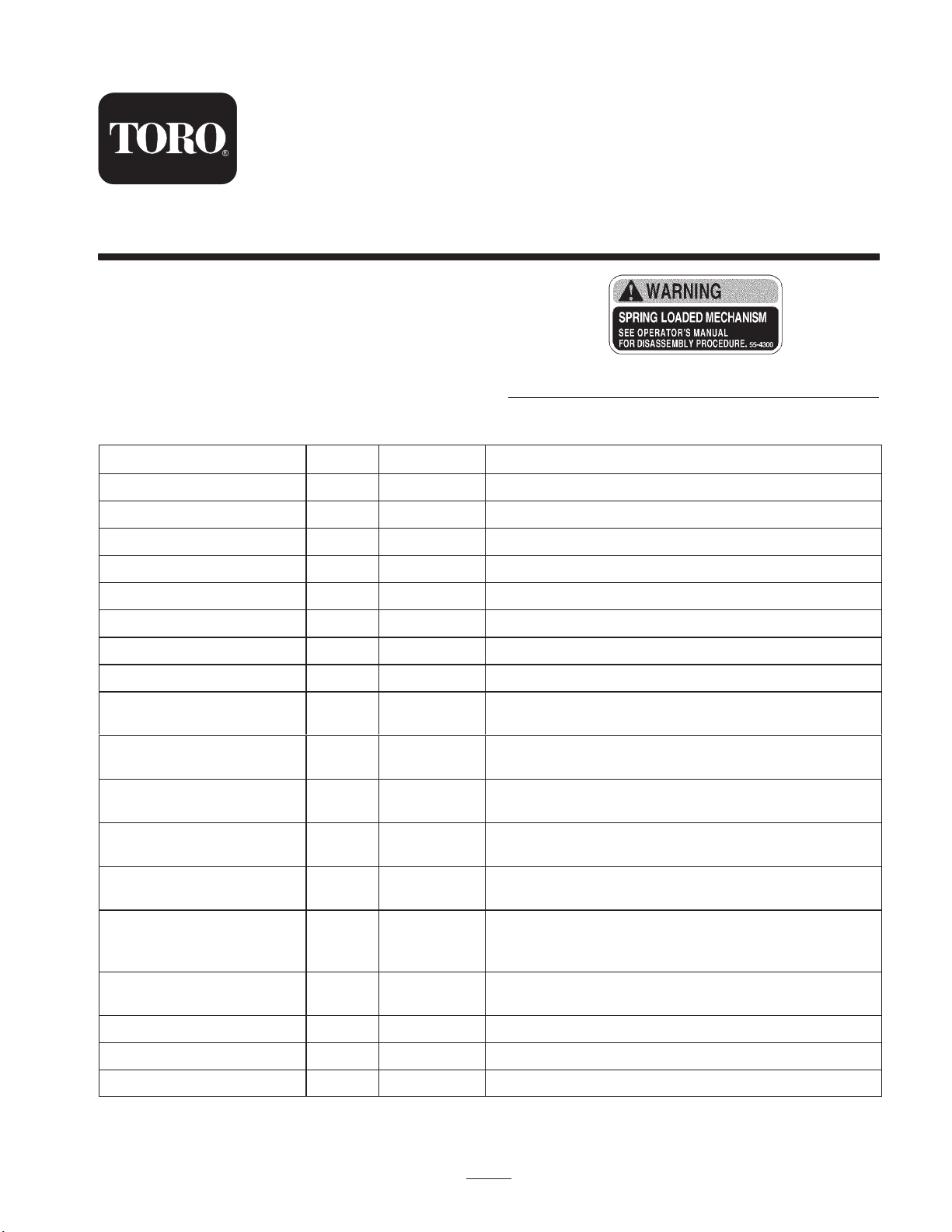
Safety and Instruction Decals
The following decal is installed on the spring cover in two
locations. If they become damaged or illegible, replace
them. The decal part number is listed below and in your
parts catalog. Replacements can be ordered from your
Authorized Toro Distributor.
Loose Part Chart
Description Qty. 52” Qty. 62”, 72” Use
Adapter bar* 0 1* Adapts bracket to 217–D and 220 models.
Mounting bracket 1 2 Spring cover mount.
Lock pin assembly 2 4 Install on bracket.
55-4300
Self-tapping screw 2 4 To secure lock pins to bracket.
Spring cover assembly 1 2 Install in bracket.
Clevis pin 1 2 Insert in spring cover & top of spring.
Hairpin cotter 1 2 Use to secure clevis pin.
Spring end—top 1 2 Install on clevis pin & top of extension spring.
Heavy extension spring 1 2
Light extension spring 0 1
Lower spring end 1 2
Knee link 1 2
Capscrew, 3/8 x 2-1/4 in. 2 4
Capscrew, 3/8 x 1 in. 2 4
Shoulder bolt 2 4
Flat washer 2 4 Use with shoulder bolt and locknut.
Install between top & bottom of spring ends
(Use one only on 62”, L.H. side).
62” only. Mount between top & bottom spring ends;
R.H. side.
Install on bottom of extension spring. Assemble
knee link to lower hole.
Attach top hole to lower spring end, bottom hole to
deck bracket.
To mount adapter bar (62”, 72”) and mounting
bracket to 217–D & 220 traction unit frames (52”).
Secures mounting brackets to adapter bar (62”, 72”)
and mounting bracket to 224 & 220–D traction unit
frames.
Attaches knee link to deck bracket and lower spring
end.
Locknut, 3/8 in. 4 12 Use with all fasteners, where necessary.
Decal–caution 2 4 Apply over decals for CE compliance
* Not included with kit; Order Part No. 66–8210 from your Authorized Toro Distributor.
2002 by The Toro Company
8111 Lyndale Avenue South
Bloomington, MN 55420-1196
1
All Rights Reserved
Printed in the USA
Page 2
Installation
Note: The cutting deck and carrier frame must be installed
on traction unit before installing the counterbalance kit.
Fully raise the cutting deck, set the parking brake, stop the
engine, and remove the ignition key. Place blocks under the
cutting deck to prevent it from falling during assembly.
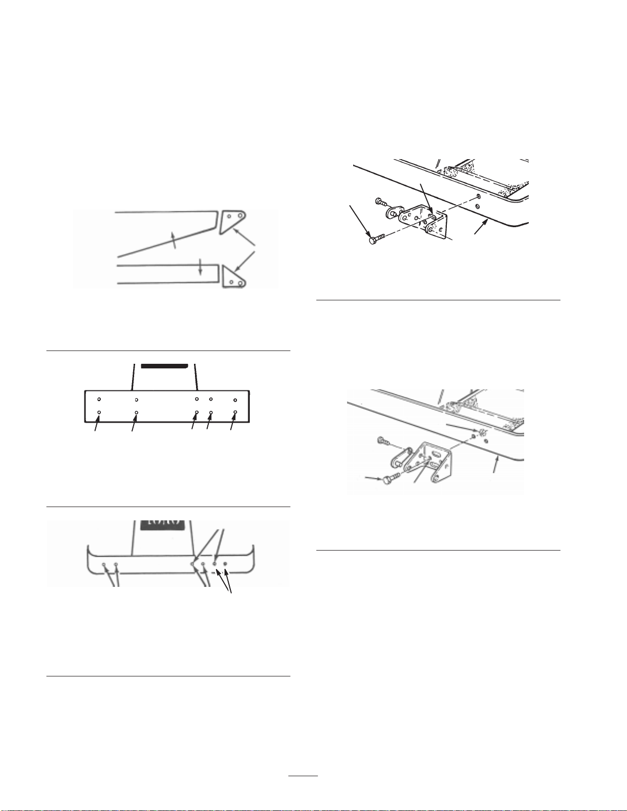
Note: Mounting brackets must be installed in different
configurations (Fig. 1) and, depending on the cutter deck,
in different locations on 220–D and 223–D, 228–D, 225,
224 and 1000L models than on the 217–D and 220 model
machines (Fig. 2, 3).
52” Cutting Decks
1. To install the mounting brackets,
• Groundsmaster 220–D, 223–D, 228–D, 225, 224
and 1000L – Insert 2 flange head capscrews (3/8 x
1 in.) through the slotted bracket holes. Thread the
screws into the captivated frame nuts and torque
them to 45–50 ft.-lb. (61–68 N⋅m) (Fig. 4).
2
1
1
Figure 1
1. 220–D, 223–D, 228–D,
225, 224 & 1000L traction
unit frame
3
GM 220–D, 223–D, 228–D, 225, 224 & 1000L
2
2. 217–D, 220 traction unit
frame
1
Figure 2
1. 52″ side discharge deck
2. 52″ deck w/bagger
3. 62″ and 72″ decks
4. 52″ rear discharge deck
2
3
Figure 4
1. Flange head capscrew
2. Slotted hole
3
3. Frame
• Groundsmaster 217–D and 220 – Align the bracket
with the frame mounting holes. Insert 2 flange head
capscrews (3/8 x 2–1/4 in.) through the non–slotted
bracket holes and frame mounting holes. Install lock
nuts and torque them to 45–50 ft.-lb. (61–68 N⋅m)
(Fig. 5)
3
4
3
1
4
2
Figure 5
1
1. Flange head capscrew
2. Non–slotted hole
3. Locknut
4. Frame
1,3
GM 217–D & 220
1. Adapter bar mount holes
(62” & 72” C.U.)
2. 52” Side discharge deck
Figure 3
4
2
3. 52” Side discharge
w/bagger
4. 52” Rear discharge deck
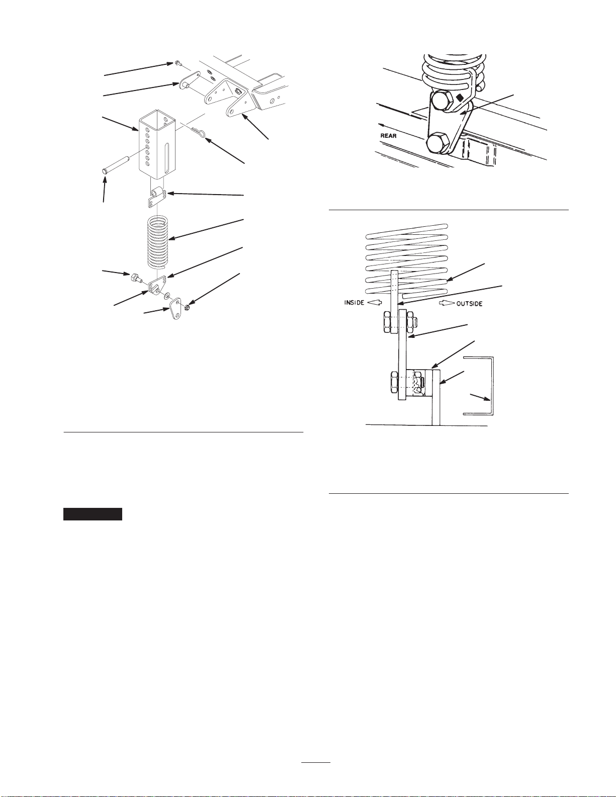
2. Thread the top extension spring coil into the top spring
end holes and the bottom extension spring coil into the
bottom spring end holes (Fig. 6).
2
Page 3
4
3
2
8
11
12
10
1. Mounting bracket
2. Spring cover
3. Lock pin assembly
4. Self-tapping screw
5. Extension spring
6. Top spring end
7. Bottom spring end
Figure 6
9
6
5
7
13
8. Clevis pin
9. Hairpin cotter
10. Knee link
11. Shoulder bolt
12. Spring end stop
13. Locknut (2)
1
1
Figure 7
1. Wide part of knee link
1
2
3
4
5
6
3. Mount each knee link to the lower spring end with the
wide part of the knee link pointing forward and the
spring end stop pointing forward. Secure the knee link
to the outer side of the spring end (Fig. 8) with a
shoulder bolt, washer, and locknut (Fig. 6 and 7).
Important The knee link must be assembled pointing
in the proper direction or the spring will not pivot correctly
when the deck is raised.
4. Mount the bottom of the knee link to the deck bracket
with a shoulder bolt, flatwasher and locknut.
5. Align the slotted holes in the spring cover (slot toward
the bottom) with the mounting bracket holes. Insert the
lock pin assemblies into the bracket holes and secure
each to the bracket with the self-tapping screws (Fig. 6).
Torque the screws to 20 ft.-lb. (27 N⋅m).
Figure 8
1. Weight transfer spring
2. Spring end plate
3. Knee link bracket
4. Deck bracket
5. Deck frame
6. Flotation frame
6. From the bottom, insert the spring and top spring end
into the spring cover. Select a hole that matches the
cutter deck height-of-cut setting; i.e., the top cover hole
matches the highest height setting, the bottom cover
hole the lowest, etc. Align the top spring end hole with
the selected spring cover holes and insert the clevis pin
to secure the spring inside the cover (Fig. 6). Secure the
clevis pin with a hairpin cotter.
7. Remove the blocks from under the cutting unit. Make
the final counterbalance adjustments under actual
cutting conditions; refer to Final Adjustments.
62” and 72” Cutting Decks
1. On 217–D and 220 models, install the adapter bar to the
front of the front of the traction unit frame
(optional–not included with frame with 4 flange head
capscrews (3/8 x 2–1/4 in.) and locknuts (Fig. 9).
3
Page 4
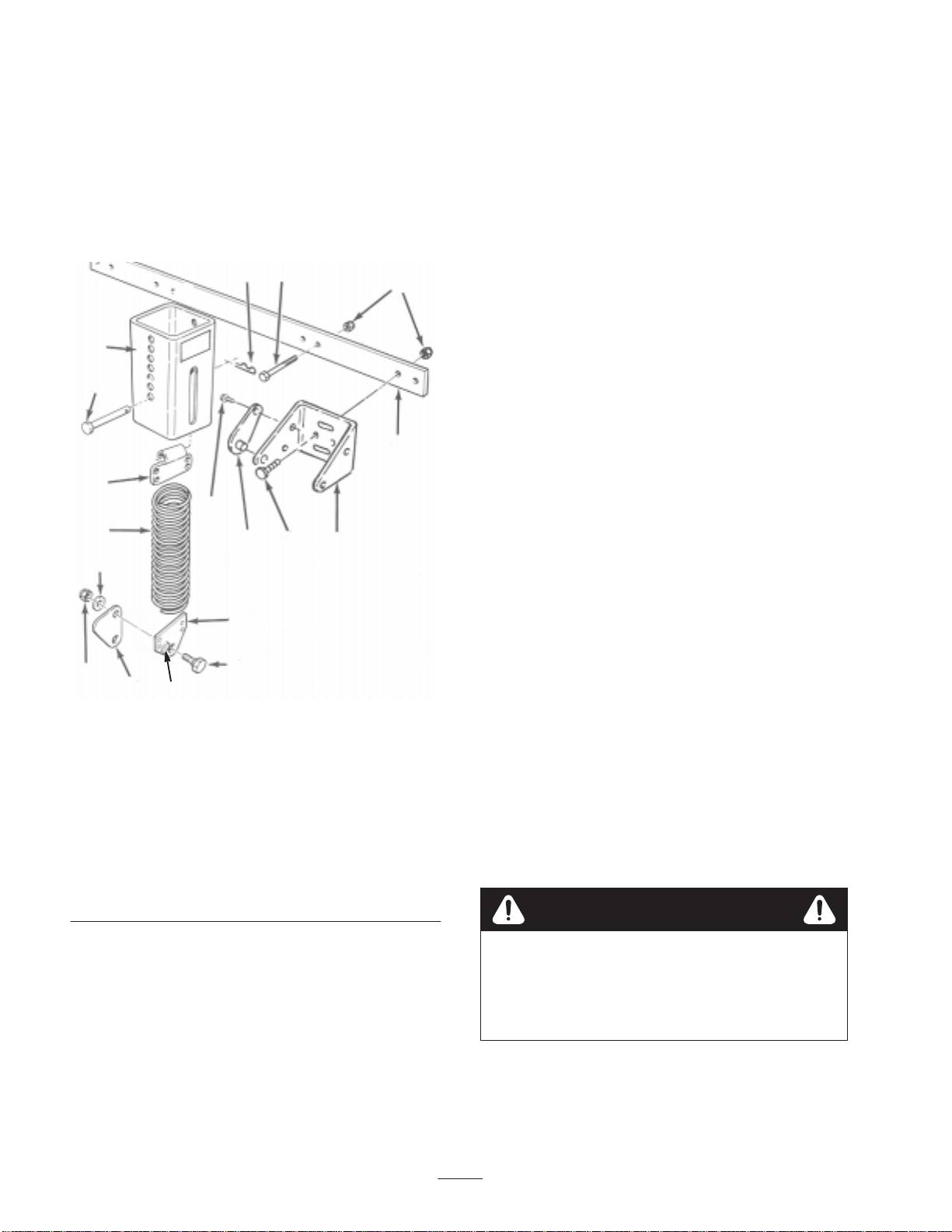
2. At each bracket, align the slotted holes in the spring
cover (slot toward the bottom) with the mounting
bracket holes. Insert lock pin assemblies into the
bracket holes and secure to the bracket with
self–tapping screws (Fig. 9). Torque the screws to
20 ft.-lb. (27 N⋅m)
3. Thread the top extension spring coils into the top spring
end holes and the bottom extension spring coils into the
bottom spring end holes (Fig. 9).
4
13
5
8
12
1
6. Position mounting brackets in the proper configuration
(Figure 1). Secure brackets to 217–D and 220 models
with (4) flange head capscrews (3/8 x 1 in.). Torque the
fasteners to 45–50 ft.-lb. (61–68 N⋅m).
Note: 62” cutting decks use a heavy rate extension spring
on the left hand side (large diameter spring wire) and light
rate extension spring on the right hand side (small diameter
spring wire)
7. From the bottom, insert the spring and top spring end
into the spring cover. Select a hole that matches the
cutter deck height-of-cut setting; i.e., the top cover hole
matches the highest height setting, the bottom cover
hole the lowest, etc. Align the top spring end hole with
the selected spring cover holes and insert the clevis pin
to secure the spring inside the cover (Fig. 6). Secure the
clevis pin with a hairpin cotter.
8. Remove the blocks from under the cutting unit. Make
the final counterbalance adjustments under actual
cutting conditions; refer to Final Adjustments.
9
10
17
18
1. Adapter (217–D & 220
2. Mounting bracket
3. 3/8 x 1” capscrew
4. 3/8 x 2–1/4” capscrew
5. Locknut
6. Lock pin assembly
7. Self-tapping screw
8. Spring cover
9. Top spring end
models)
14
16
7
11
15
Figure 9
6
10. Extension spring
11. Bottom spring end
12. Clevis pin
13. Hairpin cotter
14. Knee link
15. Shoulder bolt
16. Spring end stop
17. Flatwasher
18. Locknut
Final Adjustments
For best performance, adjust spring tension so cutting unit
23
bounce on uneven turf is minimal and it does not ride
heavily over flat terrain. If scalping occurs or the cut is
uneven from side to side, there may too much weight on the
deck and weight may have to be transferred to the traction
unit: i.e. increased spring tension.
By contrast, if too much weight is transferred to the traction
unit, the deck will bounce excessively and the cut will be
uneven. If the cutting unit does not perform properly, adjust
the tension spring as follows:
1. Stop the machine on a level surface, set the parking
brake, fully raise the cutting unit, turn the ignition key
to Off, and remove the key.
2. Remove the hairpin cotter from the clevis pin securing
the spring end to the spring cover and remove the clevis
pin. Align the top spring end hole with the new hole
selected in the spring cover, insert the clevis pin, and
secure it with the hairpin cotter. On 62” and 72” units,
ensure the same holes are selected in each spring cover
Caution
4. Mount each knee link to the lower spring end with the
wide part of the knee link pointing forward and the
spring end stop pointing forward. Secure the knee link
to the outer side of the spring end (Fig. 8) with a
shoulder bolt, washer, and locknut (Fig. 6 and 7).
5. Mount the bottom of the knee link to the deck bracket
with a shoulder bolt, flatwasher and locknut.
The counterbalance spring is in tension when the
deck is in the lowered position.
Always raise the deck before adjusting or
removing the spring.
3. Resume operations. If further adjustments are required,
repeat the procedure.
4
 Loading...