

Toro 07052, 7050 Operator's Manual

66” Rake–O–Vac Sweeper
PTO and Engine Driven
Model No. 07050–220000001 and up
Model No. 07052–220000001 and up
Form No. 3329–240
Operator ’s Manual
Domestic English (EN)

Warning
CALIFORNIA
Proposition 65 Warning
The engine exhaust from this product contains
chemicals known to the State of California to cause
cancer, birth defects, or other reproductive harm.
Important The engine in this product is not equipped
with a spark arrester muffler. It is a violation of California
Public Resource Code Section 4442 to use or operate this
engine on any forest-covered, brush-covered, or
grass-covered land as defined in CPRC 4126. Other states
or federal areas may have similar laws.
This spark ignition system complies with Canadian
ICES-002.
Ce système d’allumage par étincelle de véhicule est
conforme à la norme NMB-002 du Canada.
Contents
Page
Introduction 3. . . . . . . . . . . . . . . . . . . . . . . . . . . . . . . .
Safety 3. . . . . . . . . . . . . . . . . . . . . . . . . . . . . . . . . . . . .
Safety and Instruction Decals 5. . . . . . . . . . . . . . . .
Specifications 7. . . . . . . . . . . . . . . . . . . . . . . . . . . . . . .
Dimensions and Weights (approx.) 7. . . . . . . . . . .
Optional Equipment 7. . . . . . . . . . . . . . . . . . . . . . .
Setup 8. . . . . . . . . . . . . . . . . . . . . . . . . . . . . . . . . . . . .
Remove, Activate And Charge Battery 8. . . . . . . .
Install Battery 8. . . . . . . . . . . . . . . . . . . . . . . . . . . .
Mount Sweeper To Prime Mover 9. . . . . . . . . . . . .
Connecting Drive Shaft to Prime Mover PTO Shaft 10
Removing Sweeper From Prime Mover 10. . . . . . . .
Before Operating 11. . . . . . . . . . . . . . . . . . . . . . . . . . . .
Check Engine Oil 11. . . . . . . . . . . . . . . . . . . . . . . . .
Check Clutch Housing Oil 11. . . . . . . . . . . . . . . . . .
Fill Fuel Tank 12. . . . . . . . . . . . . . . . . . . . . . . . . . . .
Check Tire Pressure 12. . . . . . . . . . . . . . . . . . . . . . .
Transport Hooks 13. . . . . . . . . . . . . . . . . . . . . . . . . .
Adjust Reel Support Arm 13. . . . . . . . . . . . . . . . . . .
Adjust Rake Depth 13. . . . . . . . . . . . . . . . . . . . . . . .
Adjust Rubber Flap 14. . . . . . . . . . . . . . . . . . . . . . .
Page
Operation 14. . . . . . . . . . . . . . . . . . . . . . . . . . . . . . . . . .
Controls 14. . . . . . . . . . . . . . . . . . . . . . . . . . . . . . . .
Starting Instructions (Engine Driven) 15. . . . . . . . .
Stopping Instructions 16. . . . . . . . . . . . . . . . . . . . . .
Starting Instructions (PTO Driven) 16. . . . . . . . . . .
Operating Tips 16. . . . . . . . . . . . . . . . . . . . . . . . . . .
Inspection And Cleanup After Operation 16. . . . . . .
Maintenance 17. . . . . . . . . . . . . . . . . . . . . . . . . . . . . . . .
Lubrication 17. . . . . . . . . . . . . . . . . . . . . . . . . . . . . .
Oil Drive Chain 18. . . . . . . . . . . . . . . . . . . . . . . . . .
Oil Sweeper Jack 18. . . . . . . . . . . . . . . . . . . . . . . . .
Changing Engine Oil and Filter 18. . . . . . . . . . . . . .
General Air Cleaner Maintenance 19. . . . . . . . . . . .
Servicing Air Cleaner 19. . . . . . . . . . . . . . . . . . . . . .
Replacing Spark Plugs 19. . . . . . . . . . . . . . . . . . . . .
Removing Debris From Engine 20. . . . . . . . . . . . . .
Replace Fuel Filter 20. . . . . . . . . . . . . . . . . . . . . . . .
Changing Clutch Housing Oil 20. . . . . . . . . . . . . . .
Adjusting Clutch 20. . . . . . . . . . . . . . . . . . . . . . . . . .
Changing Rubber Flap 21. . . . . . . . . . . . . . . . . . . . .
Cleaning Blower Housing 21. . . . . . . . . . . . . . . . . .
Adjusting Belts 22. . . . . . . . . . . . . . . . . . . . . . . . . . .
Adjusting Drive Chain 24. . . . . . . . . . . . . . . . . . . . .
Changing Gear Box Oil 25. . . . . . . . . . . . . . . . . . . .
Gear Box Removal 25. . . . . . . . . . . . . . . . . . . . . . . .
Locking Collar Removal 26. . . . . . . . . . . . . . . . . . .
Pulley Removal 26. . . . . . . . . . . . . . . . . . . . . . . . . .
Flex Tip Reel Removal 26. . . . . . . . . . . . . . . . . . . . .
Thatcher Installation 27. . . . . . . . . . . . . . . . . . . . . . .
Flex Tip Rake Rod Or Finger Plate Replacement 27
Flex Tip Rake Tine Replacement 28. . . . . . . . . . . . .
Brush Half Replacement 28. . . . . . . . . . . . . . . . . . . .
Changing Tires 29. . . . . . . . . . . . . . . . . . . . . . . . . . .
Battery Care 29. . . . . . . . . . . . . . . . . . . . . . . . . . . . .
The Toro General Commercial Products Warranty 32. .
2002 by The Toro Company
8111 Lyndale Avenue South
Bloomington, MN 55420-1196
All Rights Reserved
Printed in the USA
2

Introduction
Safety
Read this manual carefully to learn how to operate and
maintain your product properly. The information in this
manual can help you and others avoid injury and product
damage. Although Toro designs and produces safe
products, you are responsible for operating the product
properly and safely.
Whenever you need service, genuine Toro parts, or
additional information, contact an Authorized Service
Dealer or Toro Customer Service and have the model and
serial numbers of your product ready. Figure 1 illustrates
the location of the model and serial numbers on the
product.
1
Figure 1
1. Model & serial number plate
Write the product model and serial numbers in the space
below:
Model No.
Serial No.
The RAKE–O–VAC was designed and tested to offer
safe service when operated and maintained properly.
Although hazard control and accident prevention
partially are dependent upon the design and
configuration of the machine, these factors are also
dependent upon the awareness, concern, and proper
training of the personnel involved in the operation,
transport, maintenance, and storage of the machine.
Improper use or maintenance of the machine can result
in injury or death. To reduce the potential for injury or
death, comply with the following safety instructions.
Since the Rake–O–Vac must be towed to operate, it is
extremely important that the tow tractor be carefully
selected to assure the best performance and safe operation.
The tow tractor must have the proper wheel base and tread
width and equipped with a roll bar and seat belt to operate
safely on hilly terrain. The normal operating speed is 6 mph
but will vary with terrain and debris being picked up. The
maximum transport speed is 20 mph with slower speeds
required on hilly terrain. Refer to tractor Operator’s Manual
for information or tractor service agency if you have any
question on safe operation.
The brakes of the tow tractor must have the capacity to stop
the Rake–O–Vac with hopper fully loaded and traveling at
the maximum recommended transport speed.
The power take–off drive of the Rake–O–Vac requires a
tractor with operating speeds of 540 rpm and output power
of 20 hp or higher. Do not exceed the 540 rpm speed.
The Rake–O–Vac must comply with local road
requirements, if transported on public roads. A
Slow–moving vehicle sign has been provided. Signal lights
and brakes are not provided and may be required in some
areas.
This manual identifies potential hazards and has special
safety messages that help you and others avoid personal
injury and even death. Danger, Warning, and Caution are
signal words used to identify the level of hazard. However,
regardless of the hazard, be extremely careful.
Danger signals an extreme hazard that will cause serious
injury or death if you do not follow the recommended
precautions.
Warning signals a hazard that may cause serious injury or
death if you do not follow the recommended precautions.
Caution signals a hazard that may cause minor or moderate
injury if you do not follow the recommended precautions.
This manual uses two other words to highlight information.
Important calls attention to special mechanical
information and Note: emphasizes general information
worthy of special attention.
Before Operating
• Operate the machine only after reading and
understanding the contents of this manual. A
replacement manual is available by sending complete
model and serial number to:
The Toro Company
8111 Lyndale Avenue South
Bloomington, Minnesota 55420–1196.
• Never allow children to operate the machine or adults to
operate it without proper instructions.
• Become familiar with the controls and know how to
stop the engine/sweeper quickly.
• Keep all shields, safety devices and decals in place. If a
shield, safety device or decal is malfunctioning,
illegible, or damaged, repair or replace it before
operating the machine.
3

• Always wear substantial shoes. Do not operate machine
while wearing sandals, tennis shoes or sneakers. Do not
wear loose fitting clothing which could get caught in
moving parts and cause personal injury.
– Shut engine off and wait for all movement to stop.
The impeller may momentarily turn after other
components have stopped. Use extreme caution
when removing cover from blower housing.
• Wearing safety glasses, safety shoes, long pants and a
helmet is advisable and required by some local safety
and insurance regulations.
• Keep everyone, especially children and pets away from
the areas of operation.
• Since gasoline is highly flammable, handle it carefully.
– Use an approved gasoline container.
– Do not remove cap from fuel tank when engine is
hot or running.
– Do not smoke while handling gasoline.
– Fill fuel tank outdoors and to about one inch below
top of tank, (bottom of filler neck). Do not overfill.
– Wipe up any spilled gasoline.
While Operating
• Exhaust fumes are hazardous and could be deadly, so do
not run the engine in a confined area without adequate
ventilation.
• This product may exceed noise levels of 85 dB(A) at
the operator position. Ear protectors are recommended,
for prolonged exposure, to reduce the potential of
permanent hearing damage.
• Never carry passengers on prime mover or allow
anyone to ride on sweeper.
• Disengage clutch before starting sweeper engine.
• Using the machine demands attention. To prevent
tipping or loss of control:
– Use extreme caution around ditches, creeks or other
hazards.
– Watch for holes or other hidden hazards.
– Use caution when operating machine on a steep
slope. Reduce speed when making sharp turns or
when turning on hillsides.
– Avoid sudden stops and starts.
– Before backing up, look to the rear and assure no
one is behind the machine.
– Watch out for traffic when near or crossing roads.
Always yield the right of way.
• Before leaving operator position:
– Shift into neutral, stop prime mover and engage
parking brake.
– Disengage and lower sweeper implement.
– Shut sweeper engine off.
– Disengage P.T.O.
– Take precautions to prevent accidental starts, rolling
away, etc.
• Do not step over P.T.O. shaft to get to other side of
machine. Walk around sweeper.
• Never get on or off prime mover with P.T.O. shaft
engaged.
• If prime mover or sweeper ever vibrate abnormally,
stop immediately, turn engine off, wait for all motion to
stop and inspect for damage. Repair all damage before
commencing operation.
• Whenever machine is left unattended, be sure engine is
stopped, implement is lowered and key is removed from
ignition switch.
• Shut sweeper blower off when dumping contents of
hopper. Always stand to extreme right or left side of
hopper when opening tailgate.
• Park on a level surface, empty hopper and block wheels
before removing sweeper from prime mover.
Maintenance
• Disengage power to sweeper implement and stop engine
before servicing or making adjustments.
• Disengage power to sweeper implement and stop engine
when transporting or not in use.
• To make sure entire machine is in good condition, keep
all nuts, bolts and screws properly tightened.
• If major repairs are ever needed or assistance is
required, contact an Authorized TORO Distributor.
• To reduce potential fire hazard, keep the engine area
free of excessive grease, grass, leaves and accumulation
of dirt.
• If the engine must be running to perform a maintenance
adjustment, keep hands, feet, clothing, and any parts of
the body away from the engine and any moving parts.
Keep everyone away.
• Do not overspeed engine by changing governor settings.
To assure safety and accuracy, have an Authorized Toro
Distributor check maximum engine speed with a
tachometer. P.T.O. driven machines must not exceed
540 R.P.M.
4

• Engine must be shut off before checking oil or adding
oil to the crankcase.
• Check prime mover brakes periodically to be sure
brakes, when applied, will hold firmly. Also, check to
make sure all safety equipment is functioning properly.
Safety and Instruction Decals
Safety decals and instructions are easily visible to the operator and are located near any area
of potential danger. Replace any decal that is damaged or lost.
67-5360
• To be sure of optimum performance and safety, always
purchase genuine TORO replacement parts and
accessories. Replacement parts and accessories made by
other manufacturers could be dangerous. Such use
could void the product warranty of The Toro Company.
1. Slow moving vehicle
13-6410
13-7430
61-5950
13-2930
53-4420
13-6760
93-7307
5

92-8309
92-1581
(Model 07052)
92-1582
(Model 07052)
93-4041
6

Specifications
Note: Specifications and design are subject to change without notice.
(Model 07050): Kohler, 4 cycle air cooled 22 H.P. engine @ 3600 rpm, 41.1 cu. in.
Machine Drive
Frame All welded structural rectangular 11 ga. tubing.
Hitch (Model 07050) Pin–type, 3/4” dia. vertically adjustable in 1” increments.
(674 cc) displacement. Oil capacity is 4 pints w/filter. Mechanical fuel pump. Gas
tank capacity is 4 gallons.
(Model 07052): Powered by Power Take Off drive from prime mover–540 RPM.
Hitch (Model 07052)
Fan
Fan Drive (Model 07050)
Fan Drive (Model 07052)
Hopper
Flex Tip Reel
Flex Tip Reel Drive
(Model 07050)
Pin–type, 3/4” dia. three vertical positions for tractor hitches ranging from 7–1/4” to
17–1/4” in height.
Centrifugal type–double inlet; 4 blade, 16” wide, 23–14” diameter, 3/16” thick, high
tensile steel. Shaft mounted in self–aligning, sealed ball bearings. Blower inlet area
is 286 sq. in., blower discharge area is 255 sq. in. Twin fan hood construction for
uniform air distribution: 4–1/2” deep x 63” wide (inlet area–283 sq. in.); variable
position from weighted rubber flap.
Banded double drive belt direct from drive shaft to fan impeller drive shaft with
driver pulley, fan with driven pulley. Fan impeller runs at 1580 R.P.M. (tip speed
9100 ft./min.) at 3250 engine R.P.M.
Banded double drive belt direct from drive shaft to fan impeller drive shaft with
driver pulley, fan with driven pulley. Fan impeller runs at 1490 R.P.M. (tip speed
9100 ft./min.) with 540 PTO R.P.M.
5–3/4 cu. yd. volume; 18 gauge top section with 16 gauge bottom section–rib
reinforced; full width self cleaning semi–automatic dumping.
Forward spinning with 6 rows of teeth. All steel construction with replaceable nylon
teeth; each row containing 11 individually spring–loaded flexible sets, 552 teeth
total; shaft set in self–aligning sealed bearings. Reel supported by adjustable
counter balance springs and adjustable gauge wheels. Gauge wheels are steel
construction with non–scuffing rubber tires and sealed ball bearings; infinitely
adjustable vertically.
Banded double drive belt from engine pulley to jackshaft pulley; belt from jack shaft
(driver) pulley to flex tip reel (driven) pulley. Flex tip runs at 275 R.P.M. (tip speed
1355 ft./min.) at 3250 engine R.P.M.
Flex Tip Reel Drive
(Model 07052)
#60 roller chain from 40 tooth side shaft sprocket to 29 tooth jackshaft sprocket.
Belt jack shaft (driver) pulley flex tip reel (driven) pulley. Flex tip runs at 260 R.P.M.
(tip speed 1,230 ft./min.) with 540 R.P.M.
Dimensions and Weights
(approx.)
Width 85–1/2”
Height 79–1/2”
Length 13’ 3” (Model 07050)
14’ (Model 07052)
Empty Weight 2160 lb. (Model 07050)
1980 lb. (Model 07052)
Optional Equipment
Hard Surface Brush Kit Model No. 07162
Thatching Reel Kit Model No. 07178
Flex Tip Reel Model No. 07164
Spark Arrester Muffler* Kohler No 1218902
* Contact Your Local Kohler Dealer
7

Setup
Note: Determine the left and right side of the machine from the normal operating position.
Description Qty. Use
Clutch Adjusting Plates
Bolt
Nut
Operator’s Manual
Engine Operator’s Manual
Parts Catalog 1
Registration Card 1 Fill out and return to Toro.
Remove, Activate And Charge
Battery
(Model 07050 only)
1. If Battery is not filled with electrolyte or activated, bulk
electrolyte with 1.260 specific gravity must be
purchased from a local battery supply outlet and added
to battery.
Danger
Battery electrolyte contains sulfuric acid which is a
deadly poison and causes severe burns.
• Do not drink electrolyte and avoid contact with
skin, eyes or clothing. Wear safety glasses to
shield your eyes and rubber gloves to protect
your hands.
• Fill the battery where clean water is always
available for flushing the skin.
2
4
4
1
1
Use to torque clutch
Read before operating the machine.
2. When battery is charged, disconnect charger from
electrical outlet and battery posts. Allow battery to sit
for 5 to 10 minutes before proceeding to next step.
3. Unhook springs from battery cover, remove cover and
lift battery out of battery box.
4. Remove filler caps from battery and slowly fill each
cell until electrolyte is up to fill line.
5. Replace filler caps and connect a 3 to 4 amp battery
charger to the battery posts. Charge the battery at a rate
of 3 to 4 amperes for 4 to 8 hours.
Warning
Charging the battery produces gasses that can
explode.
Never smoke near the battery and keep sparks and
flames away from battery.
6. Remove filler caps and slowly add electrolyte to each
cell until level is up fill line. Install filler caps.
Warning
CALIFORNIA
Proposition 65 Warning
Battery posts, terminals, and related accessories
contain lead and lead compounds, chemicals
known to the State of California to cause cancer
and reproductive harm. Wash hands after
handling.
Important Do not overfill battery. Electrolyte will
overflow onto other parts of the machine and severe
corrosion and deterioration will result.
Install Battery
(Model 07050 only)
1. Slide the battery into battery box with the terminals to
the inside.
8
Warning
5. Adjust sweeper hitch tongue to same level as hitch of
prime mover as follows:
Battery terminals or metal tools could short
against metal tractor components causing sparks.
Sparks can cause the battery gasses to explode,
resulting in personal injury.
• When removing or installing the battery, do not
allow the battery terminals to touch any metal
parts of the tractor.
• Do not allow metal tools to short between the
battery terminals and metal parts of the tractor.
2. Attach the negative cable (wire from engine block) to
the negative (–) terminal of the battery.
Warning
Incorrect battery cable routing could damage the
tractor and cables causing sparks. Sparks can
cause the battery gasses to explode, resulting in
personal injury.
• Always disconnect the negative (black) battery
cable before disconnecting the positive (red)
cable.
• Always connect the positive (red) battery cable
before connecting the negative (black) cable.
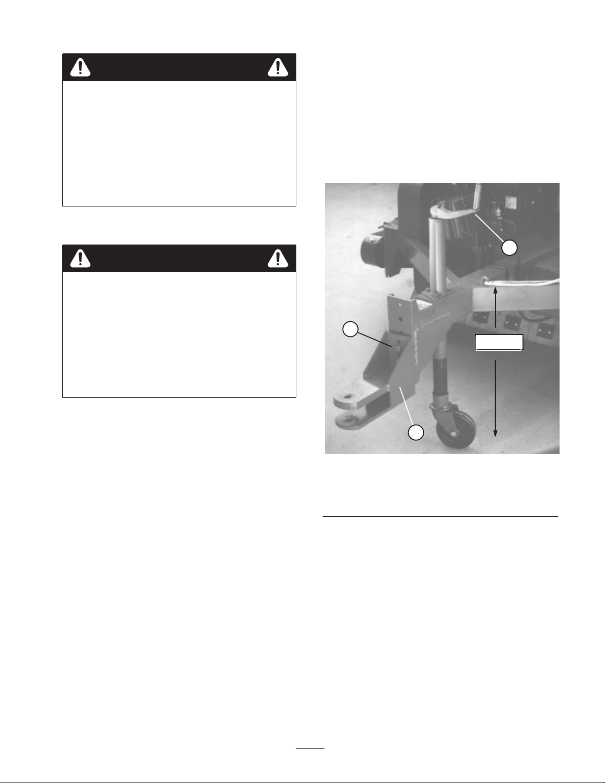
Model 07050
• Remove capscrews and locknuts securing hitch tongue
to frame (Fig. 2).
• Raise or lower hitch tongue to position approximately
level with prime move hitch and secure with (2)
capscrews and locknuts.
1
3
23–1/2”
3. Attach the positive cable (wire from ignition switch) to
the positive (+) terminal.
4. Coat the terminals and mounting fasteners with
petroleum jelly to prevent corrosion.
5. Install battery cover and secure with springs.
Mount Sweeper To Prime
Mover
To assure proper debris pickup, make sure sweeper frame is
parallel with the ground.
1. Position sweeper on a flat, level surface.
2. Insert sweeper jack caster wheel onto sweeper end of
jack tube.
3. Adjust sweeper jack so distance from top of frame to
ground is approximately 23–1/2” (Fig. 2).
4. Back prime mover up to sweeper.
2
Figure 2
1. Sweeper jack
2. Hitch tongue
(Model 07050)
3. Adjusting screws
Model 07052
• Remove front and rear capscrews and locknuts securing
hitch tongue to frame (Fig. 3).
• Raise or lower hitch tongue to position it approximately
level with prime move hitch and secure with (2)
capscrews and locknuts. The main frame should be
parallel with the ground surface about 23–1/2” when
attached to tractor.
9
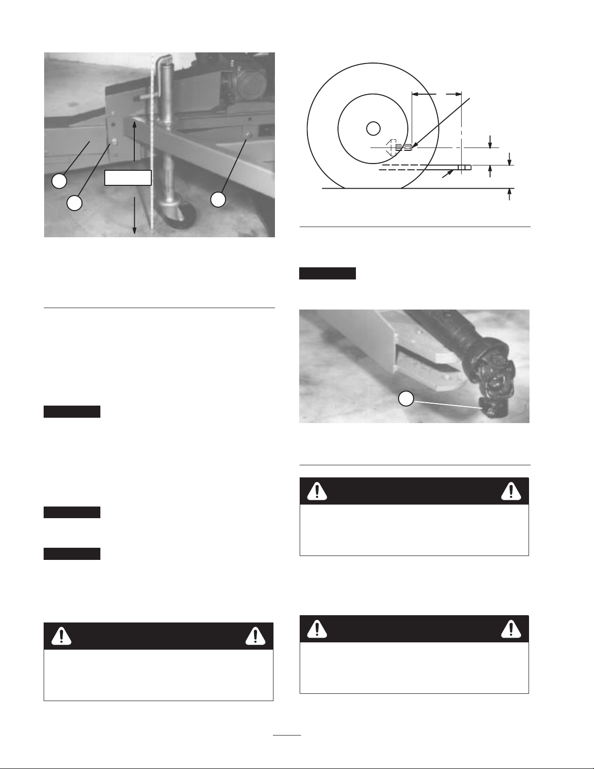
A = 13–1/2” TO 14–l/2”
B = 2–3/4” TO 11–1/2’’
C = 7–1/4” TO 17–1/4”
A
P.T.O. SHAFT
(540 RPM)
B
1
2
1. Hitch tongue
(Model 07052)
2. Front adjustment
capscrew
6. Secure sweeper hitch tongue to prime mover hitch with
hitch pin and hair pin cotter.
7. Raise sweeper jack caster wheel tube up to frame and
fold handle down.
8. Store caster wheel in compartment on left side of
machine in front of hopper.
Important After first ten hours of operation, re–tighten
capscrews and locknuts securing hitch tongue to sweeper.
23–1/2”
3
Figure 3
3. Rear adjustment
capscrew
Connecting Drive Shaft to
DRAW BAR
Figure 4
1. Attach drive shaft quick disconnect to P.T.O. shaft of
prime mover.
Important A shield should be provided on tractor to
cover drive shaft universal joint. Do not operate drive shaft
without this shield in place.
1
Figure 5
1. Drive shaft quick coupler
C
Prime Mover PTO Shaft
(Model 07052 only)
Important Mating tractor must have the dimensions
shown in figure 4. Do not operate sweeper with tractor of
different dimensions.
Important The distance (“A” Figure 4) between the
hole in the tractor hitch and the point where the drive shaft
coupler attaches to the prime mover, P.T.O. shaft must be
14’’ plus or minus 1/2”. If 14” is not attained, an
adjustment to the tractor hitch must be made before
operating sweeper.
Warning
If ”B” dimension (Fig. 4) is less than 3”, extreme
caution must be used when tractor and sweeper
unit crests tops of steep hills.
Warning
This sweeper is designed for a 540 RPM P.T.O.
shaft only. Do not operate with a 1000 RPM P.T.O.
tractor.
Removing Sweeper From
Prime Mover
Warning
Always empty sweeper hopper before
disconnecting hopper from prime mover or
sweeper may tip backwards and cause injury.
1. Park sweeper on a level surface and block wheels.
10
 Loading...