

Page 1

G132andH132Rear-EngineRidingMower
ModelNo.70185
ModelNo.70186
LooseParts
Usethechartbelowtoverifythatallpartshavebeenshipped.
FormNo.3359-686RevA
SetupInstructions
ProcedureDescription
1
2
3
4
5
6
7
Wheels2
Flatwashers,M16(3mmthick)
Spacers,M16(1mmthick)
Cotterpins
Seat
Screws,M8x18mm
Flatwashers,M94
Lockwashers4
Socketpin
Enginecover1
Screws,M6x25mm
Frame1
Fabricbagwithclips1
Handle1
Locknuts,M82
Washers,M94
Z-brackets2
Bolts,M6x35mm2
Spacers
Washers2
Nuts,M62
Grasscollectorcover
Pins2
Fullbaglever1
Bolts,M6x20mm2
Flatwashers,M6.54
Nuts,M62
Qty.
2
4
2
1
4
1Attachthesteeringwheel.
2
2
1
Installthefrontwheels.
Installtheseat.
Installtheenginecover.
Assemblethegrasscollector.
Installthegrasscollector.
Activatethebattery.
Use
8
9
10
11
©2007—TheToro®Company
8111LyndaleAvenueSouth
Bloomington,MN55420
Nopartsrequired
Nopartsrequired
Nopartsrequired
Nopartsrequired
Registeratwww.Toro.com.
–
–
–
–
Checktheoillevel.
Fillthefueltank.
Checkthetirepressure.
Testthesafetysystem.
OriginalInstructions(EN)
PrintedinItaly
AllRightsReserved
Page 2
ProcedureDescription
12
Operator’sManuals(Englishand
French)
Engineoperator’smanual1
Keys2
Sparkplugwrench
Oildraintube
Recycler®cover
Qty.
Use
2
Readthemanualbeforeoperatingor
1
1
1
servicingthemower.
1
InstallingtheFrontWheels
Partsneededforthisprocedure:
2Wheels
2
Flatwashers,M16(3mmthick)
4
Spacers,M16(1mmthick)
2
Cotterpins
Procedure
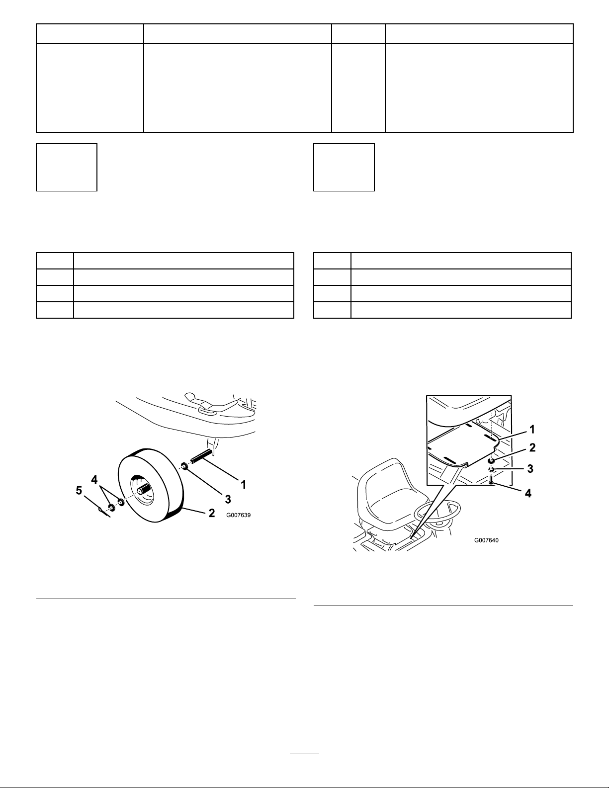
1.Slideaatwasher(M16,3mmthick)ontoeach
spindle(Figure1).
2
InstallingtheSeat
Partsneededforthisprocedure:
1
Seat
4
Screws,M8x18mm
4Flatwashers,M9
4Lockwashers
Procedure
Attachtheseattothesupportplatewith4atwashers
(M9),lockwashers,andscrews(M8x18mm)(Figure2).
Figure1
1.Spindle4.Spacers(M16,1mmthick)
2.Wheel
3.Flatwasher(M16,3mm
thick)
5.Cotterpin
2.Mountthewheelsandsecureeachofthemwith2
spacers(M16,1mmthick)andacotterpin(Figure1).
3.Greasethewheels.
Figure2
1.SeatSupportplate
2.Flatwasher(M9)4.Screw(M8x18mm)
3.Lockwasher
Note:Beforetighteningthescrews,adjusttheseattoa
positionthatismostcomfortableforyou.
2
Page 3

3
4
AttachingtheSteeringWheel
Partsneededforthisprocedure:
1
Socketpin
Procedure
1.Rotatethesteeringwheelupwarduntilitisaligned
withthesteeringcolumn.
2.Securethesteeringwheelwiththesocketpin
(Figure3).
InstallingtheEngineCover
Partsneededforthisprocedure:
1Enginecover
2
Screws,M6x25mm
Procedure
1.Slidethetabsontheenginecoverintotheslotson
thebodyofthetractor(Figure4).
1.Socketpin
Figure3
Figure4
1.Enginecover
2.Securethecoverwith2screws(M6x25mm)
(Figure4).
2.Screw
3
Page 4

5
6
AssemblingtheGrass
Collector
Partsneededforthisprocedure:
1Frame
1Fabricbagwithclips
1Handle
2Locknuts,M8
4Washers,M9
Procedure
1.Slidethebagontotheframeandsecureitwiththe
clips(Figure5).
InstallingtheGrassCollector
Partsneededforthisprocedure:
2Z-brackets
2Bolts,M6x35mm
2
Spacers
2Washers
2Nuts,M6
1
Grasscollectorcover
2Pins
1Fullbaglever
Procedure
1.Reachbeneaththerearofthetractorandholdthe
fullbagswitchandswitchplatewhileremovingthe2
screwsontherearpanel(Figure7).
Figure5
1.Bag2.Frame
2.Securethehandletothebagassemblywith4washers
(M9)and2locknuts(M8)(Figure6).
Figure6
1.Bagassembly
2.Handle
3.Washer(M9)
4.Locknut(M8)
Figure7
1.Rearpanel4.Fullbaglever
2.Switch5.Screw
3.Switchplate
2.Holdtheswitchplateagainsttheswitchandslide
thefullbagleverintotherectangularslotonthe
rearpanel.
3.Hooktheswitchplateontotheleverandsecurethe
switchandswitchplatetotherearpanelwiththe
2screws(Figure7).
4.Attachthegrasscollectortotherearofthetractor
with2bolts(M6x16.2mm),Z-brackets,spacers,
washers,andnuts(M6)(Figure8).
4
Page 5

Figure8
1.Bolt(M6x35mm)4.Grasscollector
2.Z-bracket5.Washer
3.Spacer6.Nut(M6)
5.Attachthegrasscollectorcovertothetractorwith2
pins(Figure9).
Batteryelectrolytecontainssulfuricacid,a
deadlypoisonthatcancausesevereburns.
•Donotdrinkelectrolyteandavoidcontact
withskin,eyesorclothing .Wearsafety
glassestoshieldyoureyesandrubbergloves
toprotectyourhands.
•Fillthebatterywherecleanwaterisalways
availableforushingtheskin.
•Followallinstructionsandcomplywithall
safetymessagesontheelectrolytecontainer.
1.Removethebatteryfromthetractorandplaceiton
alevelsurface;refertoRemovingtheBatteryinthe
Operator’sManual.
Important:Neverllthebatterywith
electrolytewhilethebatteryisinstalledinthe
tractor.Youcouldspillelectrolyteonotherparts
andcausecorrosion.
2.Cleanthetopofthebatterywithapapertowel.
3.Removetheventcapsfromthebattery(Figure10).
Figure9
1.Grasscollectorcover
2.Pin
7
ActivatingtheBattery
Partsneededforthisprocedure:
2Bolts,M6x20mm
4Flatwashers,M6.5
2Nuts,M6
Procedure
Purchasebulkelectrolytewith1.260specicgravity
fromalocalbatterysupplyoutlet.
Figure10
1.Ventcaps3.Lowerline
2.Upperline
4.Slowlypourelectrolyteintoeachbatterycelluntil
theelectrolytelevelisuptotheupperlineonthe
batterycase(Figure10).
Important:Donotoverllthebatterybecause
electrolyte(sulfuricacid)canseverelycorrode
anddamagethechassis.
5.Wait5to10minutesafterllingthebatterycells,
thenaddelectrolyte,ifnecessary,untiltheelectrolyte
levelisuptotheupperline(Figure10)onthebattery
case.
6.Installthebatteryventcaps.
7.Chargethebatteryfor1hourat25to30ampsor
6hoursat4to6amps.Donotoverchargethe
battery.
5
Page 6

Chargingthebatteryproducesgassesthatcan
explode.
Neversmokenearthebatteryandkeepsparks
andamesawayfrombattery.
8.Whenthebatteryisfullycharged,unplugthecharger
fromtheelectricaloutlet,thendisconnectthe
chargerleadsfromthebatteryposts(Figure11).
Figure11
1.Positivepost
2.Negativepost
9.Installthebatteryinthetractorandconnectthe
batterycables;refertoInstallingtheBatteryinthe
Operator’sManual.
3.Chargerred(+)wire
4.Chargerblack(–)wire
9
FillingtheFuelTank
NoPartsRequired
Procedure
Addfueltothefueltank;refertoFillingtheFuelTank
intheOperator’sManual.
10
CheckingtheTirePressure
NoPartsRequired
Procedure
Checkthefrontandreartiresforproperination;refer
toCheckingtheTirePressureintheOperator’sManual.
11
8
CheckingtheEngineOilLevel
NoPartsRequired
Procedure
Beforeyoustarttheengineandusethetractor,check
theoillevelintheenginecrankcase;refertoChecking
theOilLevelintheOperator’ sManual.
TestingtheSafetySystem
NoPartsRequired
Procedure
Testthesafetyinterlocksystem;refertoTheSafety
InterlockSystemintheOperator’ sManual.
6
Page 7

12
ReadingtheManual
Partsneededforthisprocedure:
2
Operator’sManuals(EnglishandFrench)
1Engineoperator’smanual
2Keys
1
Sparkplugwrench
1
Oildraintube
1
Recycler®cover
Procedure
•ReadtheOperator’sManual.
•Readtheengineowner’ smanual.
•Usetheignitionkeytostarttheengineandthe
KeyChoicekeytooperatethemowerinreverse
(refertotheOperator’sManual).
•Usethesparkplugwrenchtoservicethesparkplug
(refertotheOperator’sManual).
•Usetheoildraintubewhenyouchangetheengine
oil(refertotheOperator’sManual).
•UsetheRecyclercoverwhenrecyclingthegrass
clippings(refertotheOperator’ sManual).
7
Page 8

 Loading...