

Page 1

Form No. 3327-645 Rev A
13-32H
Wheel Horse Rear Engine Rider
Model No. 70184—Serial No. 220000001 and Up
Operator ’s Manual
International English (GB)
Page 2
Important The engine in this product is not equipped
with a spark arrester muffler. In some areas it is a violation
of the law to use or operate this engine on any
forest-covered, brush-covered, or grass-covered land.
This spark ignition system complies with Canadian
ICES-002.
Ce système d’allumage par étincelle de véhicule est
conforme à la norme NMB-002 du Canada.
Contents
Page
Introduction 2. . . . . . . . . . . . . . . . . . . . . . . . . . . . . . . .
Safety 3. . . . . . . . . . . . . . . . . . . . . . . . . . . . . . . . . . . . .
Safe Operation Practices for Ride-on (riding) Rotary
Lawnmower Machines 3. . . . . . . . . . . . . . . . . . .
Safe Operating Practices 3. . . . . . . . . . . . . . . . . . . .
Toro Riding Mower Safety 5. . . . . . . . . . . . . . . . . .
Sound Pressure Level 5. . . . . . . . . . . . . . . . . . . . . .
Sound Power Level 5. . . . . . . . . . . . . . . . . . . . . . .
Vibration Level 5. . . . . . . . . . . . . . . . . . . . . . . . . . .
Slope Chart 7. . . . . . . . . . . . . . . . . . . . . . . . . . . . . .
Safety and Instruction Decals 9. . . . . . . . . . . . . . . .
Gasoline and Oil 11. . . . . . . . . . . . . . . . . . . . . . . . . . . . .
Recommended Gasoline 11. . . . . . . . . . . . . . . . . . . .
Using Stabilizer/Conditioner 11. . . . . . . . . . . . . . . .
Filling the Fuel Tank 11. . . . . . . . . . . . . . . . . . . . . .
Checking the Engine Oil Level 11. . . . . . . . . . . . . .
Operation 12. . . . . . . . . . . . . . . . . . . . . . . . . . . . . . . . . .
Think Safety First 12. . . . . . . . . . . . . . . . . . . . . . . . .
Controls 12. . . . . . . . . . . . . . . . . . . . . . . . . . . . . . . .
Parking Brake 12. . . . . . . . . . . . . . . . . . . . . . . . . . . .
Positioning the Seat 12. . . . . . . . . . . . . . . . . . . . . . .
Using the Blade Control (PTO) 13. . . . . . . . . . . . . .
Setting the Height of Cut 13. . . . . . . . . . . . . . . . . . .
Starting and Stopping the Engine 13. . . . . . . . . . . . .
The Safety Interlock System 14. . . . . . . . . . . . . . . .
Driving Forward or Backward 16. . . . . . . . . . . . . . .
Stopping the Machine 16. . . . . . . . . . . . . . . . . . . . . .
Emptying the Grass Collector 16. . . . . . . . . . . . . . .
Pushing the Machine by Hand 17. . . . . . . . . . . . . . .
Installing the Recycler Cover 17. . . . . . . . . . . . . . .
Tips for Mowing Grass 18. . . . . . . . . . . . . . . . . . . . .
Maintenance 19. . . . . . . . . . . . . . . . . . . . . . . . . . . . . . . .
Recommended Maintenance Schedule 19. . . . . . . . .
Servicing the Engine Oil 20. . . . . . . . . . . . . . . . . . .
Servicing the Battery 21. . . . . . . . . . . . . . . . . . . . . .
Servicing the Air Cleaner 23. . . . . . . . . . . . . . . . . . .
Servicing the Spark Plug 25. . . . . . . . . . . . . . . . . . .
Checking the Tire Pressure 25. . . . . . . . . . . . . . . . . .
2002 by The Toro Company
8111 Lyndale Avenue South
Bloomington, MN 55420-1196
Page
Greasing and Lubrication 25. . . . . . . . . . . . . . . . . . .
Checking the Parking Brake 25. . . . . . . . . . . . . . . . .
Draining the Fuel Tank 26. . . . . . . . . . . . . . . . . . . . .
Replacing the Fuel Filter 26. . . . . . . . . . . . . . . . . . .
Servicing the Fuses 26. . . . . . . . . . . . . . . . . . . . . . . .
Servicing the Cutting Blade 27. . . . . . . . . . . . . . . . .
Leveling the Mower 28. . . . . . . . . . . . . . . . . . . . . . .
Washing the Underside of the Mower 28. . . . . . . . .
Washing the Machine 29. . . . . . . . . . . . . . . . . . . . . .
Cleaning and Storage 29. . . . . . . . . . . . . . . . . . . . . .
Wiring Diagram 30. . . . . . . . . . . . . . . . . . . . . . . . . .
Troubleshooting 31. . . . . . . . . . . . . . . . . . . . . . . . . . . . .
Introduction
Read this manual carefully to learn how to operate and
maintain your product properly. The information in this
manual can help you and others avoid injury and product
damage. Although Toro designs and produces safe
products, you are responsible for operating the product
properly and safely.
Whenever you need service, genuine Toro parts, or
additional information, contact an Authorized Service
Dealer or Toro Customer Service and have the model and
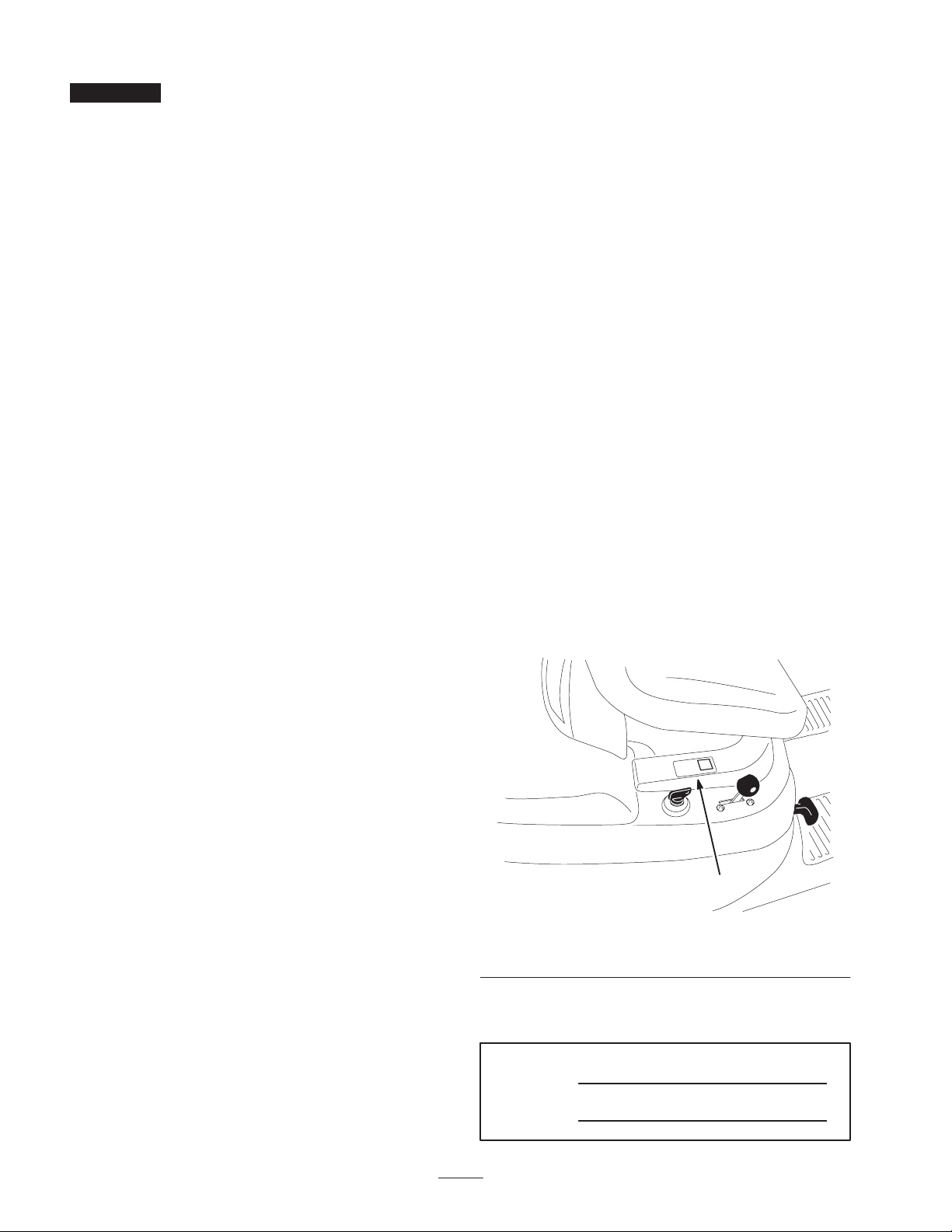
serial numbers of your product ready. Figure 1 illustrates
the location of the model and serial numbers on the
product.
1
m–5975
Figure 1
1. Location of the model and serial numbers
Write the product model and serial numbers in the space
below:
Model No.
Serial No.
All Rights Reserved
Printed in the USA
2
Page 3

This manual identifies potential hazards and has special
safety messages that help you and others avoid personal
injury and even death. Danger, Warning, and Caution are
signal words used to identify the level of hazard. However,
regardless of the hazard, be extremely careful.
Danger signals an extreme hazard that will cause serious
injury or death if you do not follow the recommended
precautions.
Warning signals a hazard that may cause serious injury or
death if you do not follow the recommended precautions.
Caution signals a hazard that may cause minor or moderate
injury if you do not follow the recommended precautions.
This manual uses two other words to highlight information.
Important calls attention to special mechanical
information and Note: emphasizes general information
worthy of special attention.
Safety
Safe Operation Practices for
Ride-on (riding) Rotary
• Keep in mind that the operator or user is responsible for
accidents or hazards occurring to other people or their
property.
• Do not carry passengers.
• All drivers should seek and obtain professional and
practical instruction. Such instruction should
emphasize:
– the need for care and concentration when working
with ride-on machines;
– control of a ride-on machine sliding on a slope will
not be regained by the application of the brake. The
main reasons for loss of control are:
• insufficient wheel grip;
• being driven too fast;
• inadequate braking;
• the type of machine is unsuitable for its task;
• lack of awareness of the effect of ground
conditions, especially slopes;
• incorrect hitching and load distribution.
Lawnmower Machines
This machine meets or exceeds European Standards in
effect at the time of production. However, improper use
or maintenance by the operator or owner can result in
injury. To reduce the potential for injury, comply with
these safety instructions and always pay attention to the
safety alert symbol, which means CAUTION,
WARNING, or DANGER—“personal safety
instruction.” Failure to comply with the instruction may
result in personal injury or death.
Safe Operating Practices
The following instructions are from the CEN standard EN
836:1997.
This product is capable of amputating hands and feet and
throwing objects. Always follow all safety instructions to
avoid serious injury or death.
Training
• Read the instructions carefully. Be familiar with the
controls and the proper use of the equipment.
Preparation
• While mowing, always wear substantial footwear and
long trousers. Do not operate the equipment when
barefoot or wearing open sandals.
• Thoroughly inspect the area where the equipment is to
be used and remove all objects which may be thrown by
the machine.
• Warning—Fuel is highly flammable.
– Store fuel in containers specifically designed for this
purpose.
– Refuel outdoors only and do not smoke while
refuelling.
– Add fuel before starting the engine. Never remove
the cap of the fuel tank or add fuel while the engine
is running or when the engine is hot.
– If fuel is spilled, do not attempt to start the engine
but move the machine away from the area of
spillage and avoid creating any source of ignition
until fuel vapors have dissipated.
– Replace all fuel tanks and container caps securely.
• Never allow children or people unfamiliar with these
instructions to use the lawnmower. Local regulations
can restrict the age of the operator.
• Never mow while people, especially children, or pets
are nearby.
• Replace faulty silencers.
• Before using, always visually inspect to see that the
blades, blade bolts and cutter assembly are not worn or
damaged. Replace worn or damaged blades and bolts in
sets to preserve balance.
3
Page 4

• On multi-bladed machines, take care as rotating one
blade can cause other blades to rotate.
Operation
• Do not operate the engine in a confined space where
dangerous carbon monoxide fumes can collect.
• Mow only in daylight or in good artificial light.
• Before attempting to start the engine, disengage all
blade attachment clutches and shift into neutral.
• Do not use on slopes of more than
–5 when mowing on side hills;
–10 when mowing uphill;
–15 when mowing downhill.
• Remember there is no such thing as a safe slope. Travel
on grass slopes requires particular care. To guard
against overturning:
– do not stop or start suddenly when going up or
downhill;
– engage clutch slowly, always keep machine in gear,
especially when travelling downhill;
– machine speeds should be kept low on slopes and
during tight turns;
– stay alert for humps and hollows and other hidden
hazards;
– never mow across the face of the slope, unless the
lawnmower is designed for this purpose.
• Before leaving the operator’s position:
– disengage the power take-off and lower the
attachments;
– change into neutral and set the parking brake;
– stop the engine and remove the key.
• Disengage drive to attachments, stop the engine, and
disconnect the spark plug wire(s) or remove the ignition
key
– before clearing blockages or unclogging chute;
– before checking, cleaning or working on the
lawnmower;
– after striking a foreign object. Inspect the
lawnmower for damage and make repairs before
restarting and operating the equipment;
– if the machine starts to vibrate abnormally (check
immediately).
• Disengage drive to attachments when transporting or
not in use.
• Stop the engine and disengage drive to attachment
– before refuelling;
– before removing the grass catcher;
– before making height adjustment unless adjustment
can be made from the operator’s position.
• Reduce the throttle setting during engine run-out and, if
the engine is provided with a shut-off valve, turn the
fuel off at the conclusion of mowing.
• Use care when pulling loads or using heavy equipment.
– Use only approved drawbar hitch points.
– Limit loads to those you can safely control.
– Do not turn sharply. Use care when reversing.
– Use counterweight(s) or wheel weights when
suggested in the instruction handbook.
• Watch out for traffic when crossing or near roadways.
• Stop the blades rotating before crossing surfaces other
than grass.
• When using any attachments, never direct discharge of
material toward bystanders nor allow anyone near the
machine while in operation.
• Never operate the machine with damaged guards or
without safety protective devices in place.
• Do not change the engine governor settings or
overspeed the engine. Operating the engine at excessive
speed can increase the hazard of personal injury.
Maintenance and Storage
• Keep all nuts, bolts and screws tight to be sure the
equipment is in safe working condition.
• Never store the equipment with fuel in the tank inside a
building where fumes can reach an open flame or spark.
• Allow the engine to cool before storing in any
enclosure.
• To reduce the fire hazard, keep the engine, silencer,
battery compartment and fuel storage area free of grass,
leaves, or excessive grease.
• Check the grass catcher frequently for wear or
deterioration.
• Replace worn or damaged parts for safety.
• If the fuel tank has to be drained, this should be done
outdoors.
• On multi-bladed machines, take care as rotating one
blade can cause other blades to rotate.
4
Page 5

• When machine is to be parked, stored or left
unattended, lower the cutting means unless a positive
mechanical lock is used.
Toro Riding Mower Safety
The following list contains safety information specific to
Toro products or other safety information that you must
know that is not included in the CEN standard.
• Use only Toro-approved attachments. Warranty may be
voided if used with unapproved attachments.
Sound Pressure Level
This unit has a maximum sound pressure level at the
operator’s ear of 87 dBA, based on measurements of
identical machines per Directive 98/37/EC.
Sound Power Level
This unit has a guaranteed sound power level of 100 dBA,
based on measurements of identical machines per Directive
2000/14/EC.
Vibration Level
This unit does not exceed a hand/arm vibration level of
2
4.5 m/s
Directive 98/37/EC.
This unit does not exceed a whole body vibration level of
0.25 m/s
Directive 98/37/EC.
based on measurements of identical machines per
2
based on measurements of identical machines per
5
Page 6

6
Page 7
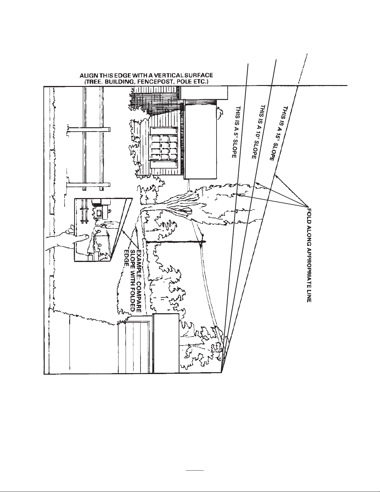
Slope Chart
7
Page 8

8
Page 9
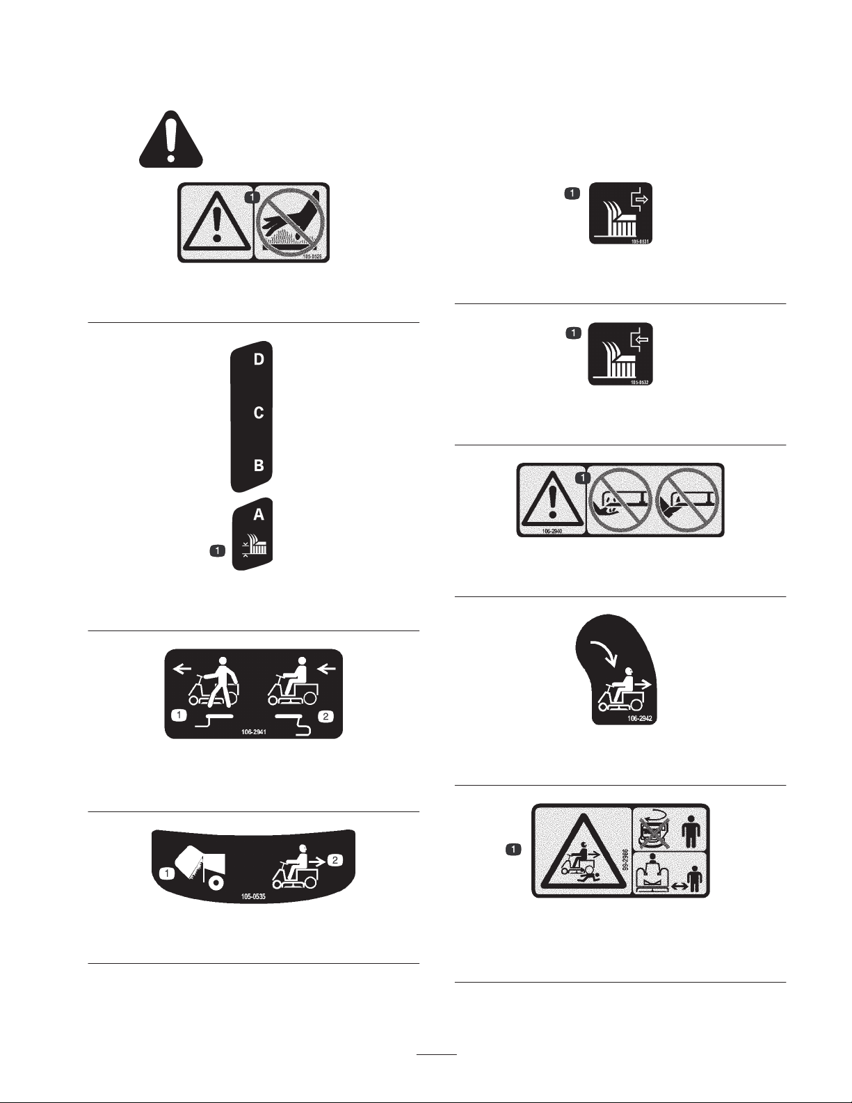
Safety and Instruction Decals
Safety decals and instructions are easily visible to the operator and are located near any area
of potential danger. Replace any decal that is damaged or lost.
105-0529
1. Warning—do not touch the hot surface.
105-0531
1. Disengage the cutting blade.
105-0532
1. Engage the cutting blade
105-0530
1. Height of cut
106-2941
1. Push the lever in to push
the machine.
2. Pull the lever out to drive
the machine.
105-0535
1. Grass collector full 2. Operating in reverse
106-2940
1. Warning—do not place you hands or feet under the mower.
106-2942
1. Turn the key to mow in reverse.
99-2986
1. Crushing/dismemberment hazard of bystanders—do not turn
the key while children are present; keep children a safe
distance from the machine.
9
Page 10
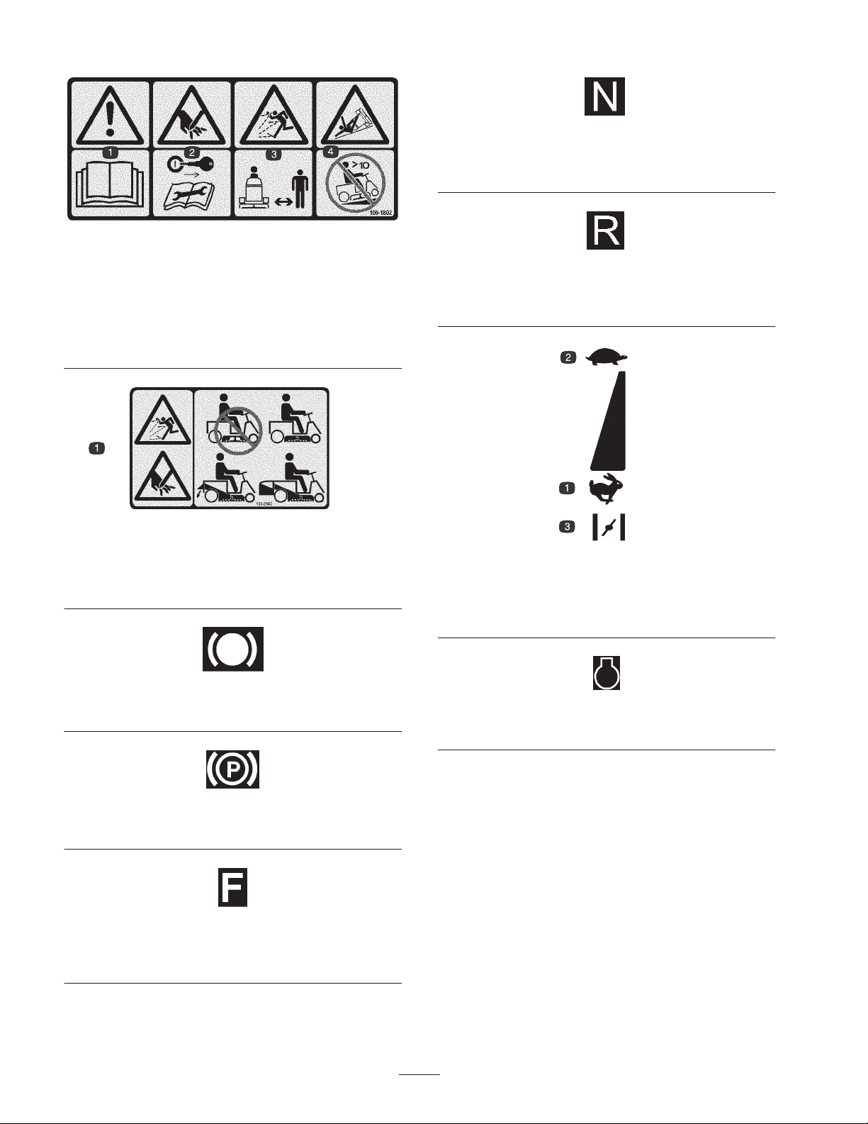
106-1802
1. Warning—read the
2. Cutting hazard of hand—remove the ignition key and read the
instructions before servicing or performing maintenance.
3. Thrown object hazard—keep bystanders a safe distance from
the machine.
4. Tipping hazard—do not drive up a slope greater than 10
degrees.
Operator’s Manual.
106-2943
1. Thrown object and cutting hazards—do not operate the
machine with the discharge opening uncovered; always
operate the machine with the recycling cover, rear discharge
deflector, or grass collector installed.
Molded into the floor near the traction control
pedal
1. Neutral
Molded into the floor near the traction control
pedal
1. Reverse
Molded into the body near the throttle control
lever
1. Fast
2. Slow
3. Choke
Molded into the floor near the brake pedal
1. Brake
Molded into the floor near the parking brake lever
1. Parking brake
Molded into the floor near the traction control
pedal
1. Forward
Molded into the body near the ignition switch
1. Engine
10
Page 11

Gasoline and Oil
Recommended Gasoline
Using Stabilizer/Conditioner
Use a fuel stabilizer/conditioner in the machine to provide
the following benefits:
Use UNLEADED Regular Gasoline suitable for automotive
use (85 pump octane minimum). Leaded regular gasoline
may be used if unleaded regular is not available.
Important Never use methanol, gasoline containing
methanol, or gasohol containing more than 10% ethanol
because the fuel system could be damaged. Do not mix oil
with gasoline.
Danger
In certain conditions, gasoline is extremely
flammable and highly explosive. A fire or
explosion from gasoline can burn you and others
and can damage property.
• Fill the fuel tank outdoors, in an open area,
when the engine is cold. Wipe up any gasoline
that spills.
• Do not fill the fuel tank completely full. Add
gasoline to the fuel tank until the level is 1/4 to
1/2 in. (6 to 13 mm) below the bottom of the
filler neck. This empty space in the tank allows
gasoline to expand.
• Never smoke when handling gasoline, and stay
away from an open flame or where gasoline
fumes may be ignited by a spark.
• Store gasoline in an approved container and
keep it out of the reach of children. Never buy
more than a 30-day supply of gasoline.
• Always place gasoline containers on the ground
away from your vehicle before filling.
• Do not fill gasoline containers inside a vehicle or
on a truck or trailer bed because interior
carpets or plastic truck bed liners may insulate
the container and slow the loss of any static
charge.
• When practical, remove gas-powered equipment
from the truck or trailer and refuel the
equipment with its wheels on the ground.
• If this is not possible, then refuel such
equipment on a truck or trailer from a portable
container, rather than from a gasoline dispenser
nozzle.
• If a gasoline dispenser nozzle must be used, keep
the nozzle in contact with the rim of the fuel
tank or container opening at all times until
fueling is complete.
• Keeps gasoline fresh during storage of 90 days or less.
For longer storage, drain the fuel tank.
• Cleans the engine while it runs
• Eliminates gum-like varnish buildup in the fuel system,
which causes hard starting
Important Do not use fuel additives containing
methanol or ethanol.
Add the correct amount of gas stabilizer/conditioner to the
gas.
Note: A fuel stabilizer/conditioner is most effective when
mixed with fresh gasoline. To minimize the chance of
varnish deposits in the fuel system, use fuel stabilizer at all
times.
Filling the Fuel Tank
1. Shut the engine off and set the parking brake.
2. Clean around the fuel tank cap and remove the cap. Add
unleaded regular gasoline to the fuel tank until the level
is 1/4 to 1/2 in. (6 to 13 mm) below the bottom of the
filler neck. This space in the tank allows gasoline to
expand. Do not fill the fuel tank completely full.
3. Install the fuel tank cap securely. Wipe up any gasoline
that may have spilled.
Checking the Engine Oil Level
Before you start the engine and use the machine, check the
oil level in the engine crankcase; refer to Checking the Oil
Level, page 20.
11
Page 12
Operation
Note: Determine the left and right sides of the machine
from the normal operating position.
Positioning the Seat
The seat can move forward and backward. Position the seat
where you have the best control of the machine and are
most comfortable.
Think Safety First
Please carefully read all of the safety instructions and
decals in the safety section. Knowing this information
could help you, your family, pets, or bystanders avoid
injury.
Controls
Become familiar with all of the controls before you start the
engine and operate the machine.
Parking Brake
Always set the parking brake when you stop the machine or
leave it unattended.
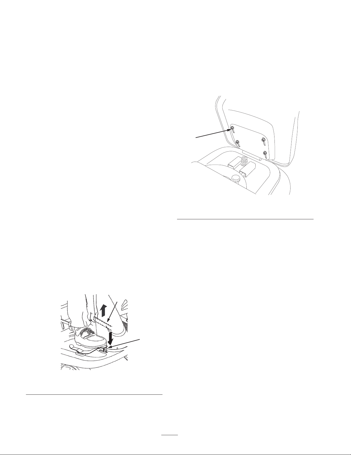
Setting the Parking Brake
1. Push the brake pedal (Fig. 2) down and hold it in the
depressed position.
2. Lift the parking brake lever (Fig. 2) up and gradually
take your foot off of the brake pedal. The brake pedal
should stay in the depressed (locked) position.
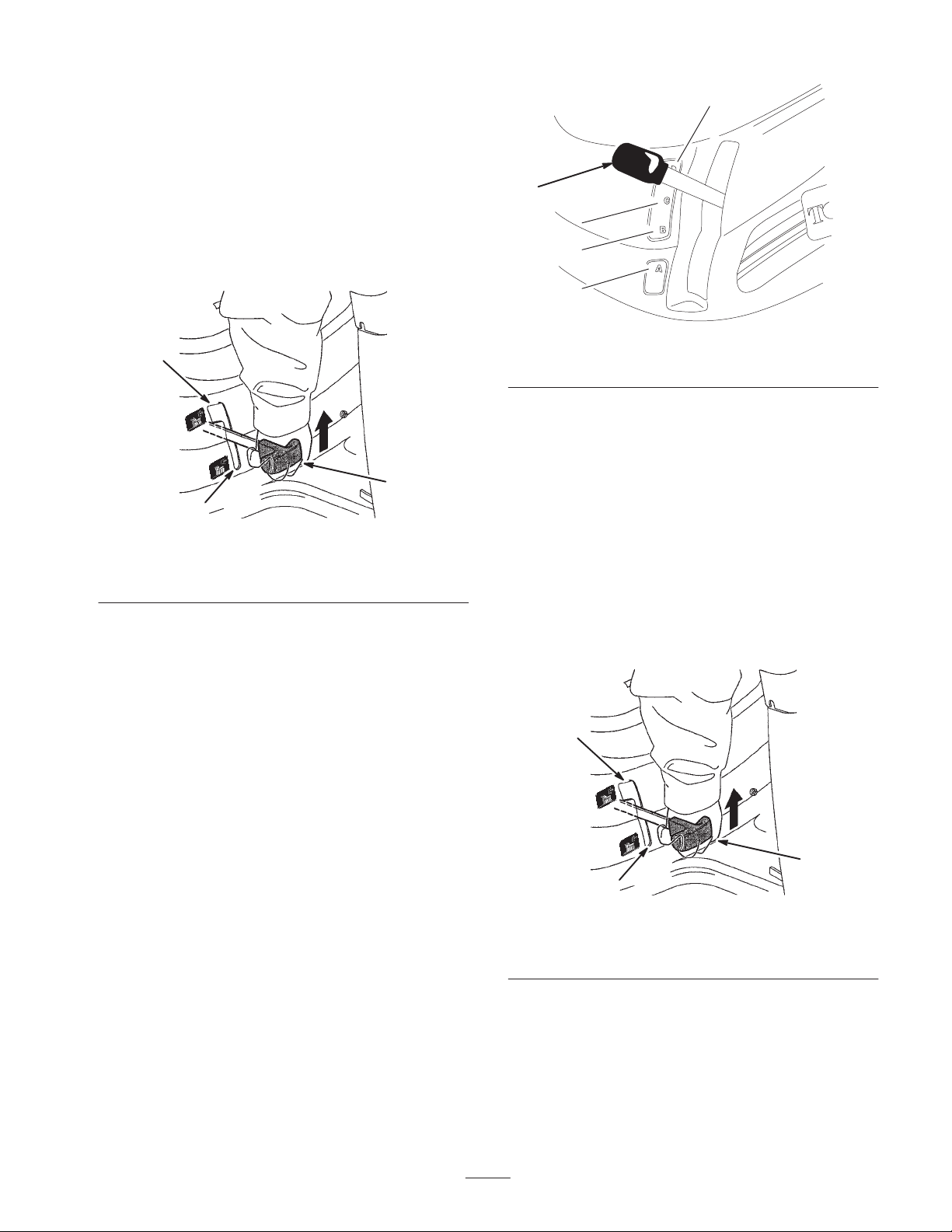
1. Raise the seat and loosen the 4 bolts (Fig. 3).
2. Move the seat to the desired position and tighten the
bolts.
1
m–5951
Figure 3
1. Bolt
Releasing the Parking Brake
1. Push down on the brake pedal (Fig. 2) and hold it in the
depressed position.
2. Push the parking brake lever (Fig. 2) down and
gradually release the brake pedal.
2
1
Figure 2
1. Brake pedal 2. Parking brake lever
12
Page 13
Using the Blade Control (PTO)
The blade control (PTO) engages and disengages power to
the blade.
9 cm
Engaging the Blade
1. Depress the brake pedal to stop the machine.
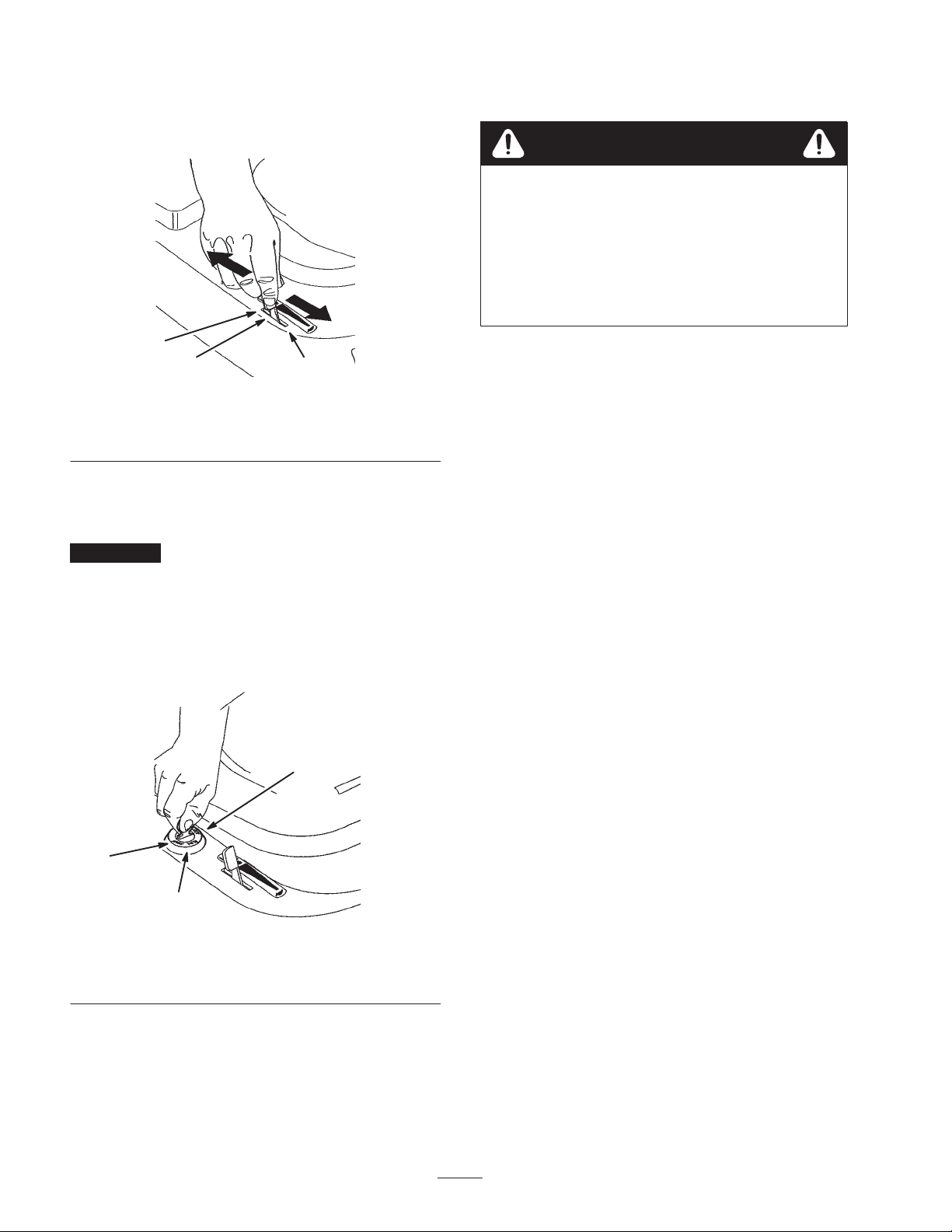
2. Slowly move the blade control (PTO) to Engaged
(Fig. 4).
2
3
1
Figure 4
1. Disengaged
2. Engaged
3. Blade control (PTO)
1
7.5 cm
5.5 cm
3.8 cm
m–5952
Figure 5
1. Height-of-cut lever (deck lift)
Starting and Stopping the
Engine
Starting
1. Sit down on the seat.
2. Set the parking brake; refer to Setting the Parking
Brake, page 12.
Note: The engine will not start unless you engage the
parking brake.
Disengaging the Blade
1. Depress the brake pedal to stop the machine.
2. Move the PTO to Disengaged (Fig. 4).
Setting the Height of Cut
The height-of-cut lever (deck lift) is used to raise and lower
the mower to the desired cutting height. The cutting height
may be set in one of 4 positions from approximately 3.8 to
9 cm.
1. Disengage the PTO.
2. Pull on the height-of-cut lever (deck lift), move it to the
desired position, and release the lever slowly until it
sticks in the notch (Fig. 5).
3. Move the PTO to Disengaged (Fig. 6).
2
1
Figure 6
1. Disengaged
2. Engaged
3. Blade control (PTO)
3
13
Page 14
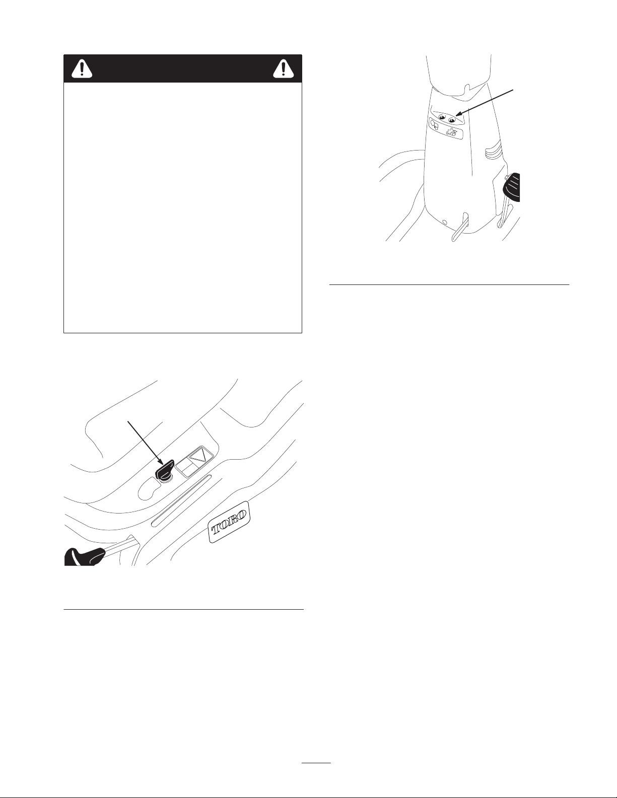
4. Move the throttle lever to Choke (Fig. 7).
Note: An engine that has been running and is warm may
not require step 4.
1
2
Figure 7
1. Choke
2. Fast
5. Turn the ignition key clockwise and hold it in the Start
position (Fig. 8). When the engine starts, release the
key.
Important If the engine does not start after 30 seconds
of continuous cranking, turn the ignition key to Stop and let
the starter motor cool; refer to Troubleshooting, page 31.
6. After the engine starts, slowly move the throttle lever to
Fast (Fig. 7). If the engine stalls or hesitates, move the
throttle lever back to Choke for a few seconds. Then
move the throttle lever to Fast. Repeat this as required.
3
3. Slow
The Safety Interlock System
Caution
If safety interlock switches are disconnected or
damaged the machine could operate unexpectedly
causing personal injury.
• Do not tamper with the interlock switches.
• Check the operation of the interlock switches
daily and replace any damaged switches before
operating the machine.
Understanding the Safety Interlock
System
The safety interlock system is designed to prevent the
engine from starting unless:
• The power-take-off (PTO) is Off.
• The operator is seated.
• The brake pedal is depressed.
The safety system is designed to stop the engine if:
• You rise from the seat when the clutch/brake pedal is
released.
• You rise from the seat when the PTO is Engaged.
• You shift into reverse with the PTO engaged and the
operating-in-reverse interlock not deactivated.
3
1
2
Figure 8
1. Start
2. Run
3. Stop
Stopping
1. Move the throttle lever to Slow (Fig. 7).
2. Turn the ignition key to Stop (Fig. 8).
Setting the KeyChoice Switch to
Operate in Reverse
An interlock feature on the tractor prevents the power take
off (PTO) from operating when backing up. If you shift into
reverse with the PTO engaged (i.e., with mower blades or
other attachment running), the engine will stop. Do not
mow in reverse unless absolutely necessary.
If you need to use the PTO while backing up, you can turn
off this interlock feature using the KeyChoice switch
located near the seat bracket (Fig. 9).
14
Page 15
Danger
You could back over a child or bystander while the
mower blade or other attachment is engaged and
cause serious injury or death.
• Do not mow in reverse unless absolutely
necessary.
• Do not insert the KeyChoice key unless it is
absolutely necessary.
• Always look backward and down before
backing up.
• Use the KeyChoice switch only if you are certain
no children or other bystanders will enter the
mowing area.
• Be very observant after deactivating the
interlock because the sound of the engine may
prevent you from noticing that a child or
bystander has entered the work area.
• Always remove both the ignition and KeyChoice
keys and put them in a safe place out of the
reach of children or unauthorized users when
leaving the unit unattended.
1. Engage the PTO.
2. Insert the KeyChoice key into the switch (Fig. 9).
1
m–5974
Figure 10
1. Operating-in-reverse light
4. Shift into reverse and complete your task.
5. Stop the PTO or the engine to activate the interlock.
6. Remove the KeyChoice key and put it in a safe place
out of reach of children.
Testing the Safety Interlock System
1
Figure 9
1. KeyChoice switch
3. Turn the KeyChoice key.
A red light on the front console (Fig. 10) turns on,
indicating that the interlock is disabled.
m–5971
Test the safety interlock system before you use the machine
each time. If the safety system does not operate as
described below, have an Authorized Service Dealer repair
the safety system immediately.
1. Move the PTO lever to Engage. Sit on the seat and
rotate the ignition key to Start; the engine should not
crank. If it does, the interlock system is malfunctioning,
and it must be repaired by an Authorized Service
Dealer. If the engine does not crank, proceed to step 2.
2. Move the PTO lever to Disengage. Sit on the seat, and
release the parking brake. Rotate the ignition key to
Start; the engine should not crank. If it does, the
interlock system is malfunctioning and must be repaired
by an Authorized Service Dealer. If the engine does not
crank, proceed to step 3.
3. Sit on the seat, put the PTO lever in the Disengage
position, and the traction control pedal in neutral.
Ensure that the parking brake is engaged. Rotate the
ignition key to Start; the engine should start and
continue to run. Then engage the PTO lever and
carefully rise from the seat; the engine should stop. If
the engine does not stop running, shut the engine off
and have the interlock system repaired by an
Authorized Service Dealer. If the engine shuts off when
you rise from the seat, the interlock system is
functioning correctly and the tractor can be operated
safely.
15
Page 16
4. Put the PTO lever in the Disengage position and the
traction control pedal in neutral. Start the engine. While
the engine is running, move the PTO lever to the
Engage position and move the traction control pedal to
reverse. The engine should stop.
5. Put the PTO lever in the Disengage position. Start the
engine. Move the PTO lever to the Engage position and
turn the KeyChoice key and release it. The KeyChoice
warning light should illuminate. Move the PTO lever to
the Disengage position and the KeyChoice warning
light should turn off.
Driving Forward or Backward
The throttle control regulates the engine speed as measured
in RPM (revolutions per minute).
To go forward or backward, release the parking brake; refer
to Releasing the Parking Brake, page 12. Place your foot on
the traction control pedal and slowly press on the top of the
traction control pedal to move forward or on the bottom of
the traction control pedal to move backward. The farther
you move the traction control pedal in either direction, the
faster the machine will move in that direction.
To slow down, release the pressure on the traction control
pedal.
Important To avoid transmission damage, always
release the parking brake before moving the traction control
pedal.
Stopping the Machine
To stop the machine, release the traction control pedal,
disengage the PTO, and turn the ignition key to Off to stop
the engine. Also set the parking brake if you leave the
machine unattended; refer to Setting the Parking Brake,
page 12. Remember to remove the key from the ignition
switch.
Caution
Children or bystanders may be injured if they
move or attempt to operate the tractor while it is
unattended.
Always remove the ignition key and set the
parking brake when leaving the machine
unattended, even if just for a few minutes.
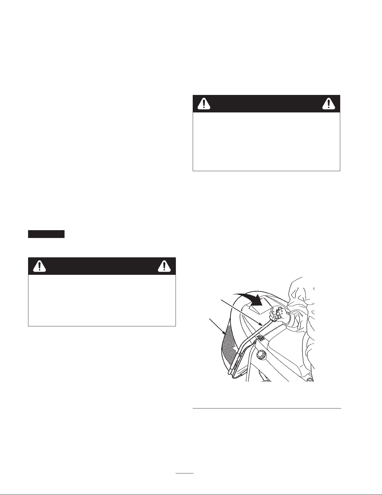
Emptying the Grass Collector
When the collector warning light on the front console
comes on, the grass collector is full and must be emptied.
1. Disengage the PTO.
2. Pull the collector rod forward to tilt the collection bin
(Fig. 11).
3. Shake the collection bin until it is completely empty.
Caution
Sudden release of the brake pedal could cause you
to lose control and suddenly put the machine in
motion.
Always release the brake pedal slowly when
starting the machine in motion.
4. Slowly return the collection rod to the operating
position.
1
2
Figure 11
1. Collector rod 2. Collection bin
16
Page 17
Pushing the Machine by Hand
Installing the Recycler Cover
Important Always push the machine by hand. Never
tow the machine because transaxle damage may occur.
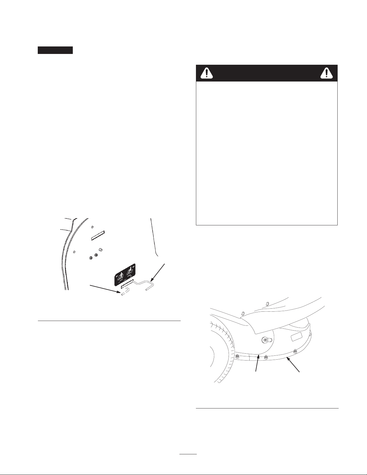
To Push the Machine
1. Disengage the PTO, stop the engine, and remove the
ignition key.
2. Raise the grass collector to access the drive control rod.
3. Push the drive control rod in and slide it to the left to
lock it in place (Fig. 12). This disengages the drive
system and allows the wheels to turn freely.
4. Lower the grass collector.
5. Disengage the parking brake to push the machine.
To Operate the Machine
1. Raise the grass collector.
2. Slide the drive control rod to the right and pull it out
(Fig. 12). This engages the drive system.
3. Lower the grass collector.
A Recycler cover is included with the tractor. It is used
when you do not wish to bag grass clippings.
Danger
Without the grass deflector, discharge cover, or
complete grass catcher assembly mounted in place,
you and others are exposed to blade contact and
thrown debris. Contact with the rotating mower
blade(s) and thrown debris will cause injury or
death.
• Never remove the grass deflector from the
mower because the grass deflector routes
material down toward the turf. If the grass
deflector is ever damaged, replace it
immediately.
• Never put your hands or feet under the mower.
• Never try to clear the discharge area or mower
blades unless you move the power take off
(PTO) to Off and rotate the ignition key to Off.
Also remove the key and pull the wire off of the
spark plug(s).
1
Figure 12
1. Push position 2. Operate position
2
m–5913
1. Park the machine on a level surface, disengage the PTO,
set the parking brake, stop the engine, and remove the
ignition key.
2. Raise the grass collector and remove the bolt securing
the discharge tube to the rear plate.
3. Move the height of cut lever into the B or C position.
Remove the 3 screws, washers, and nuts attaching the
discharge chute to the mower (Fig. 13).
2
Figure 13
1. Discharge chute 2. Discharge tube
1
m–5981
4. Remove the bolt, washer, and nut attaching the
discharge chute to the discharge tube (Fig. 13).
17
Page 18

5. Move the height of cut lever to the lowest position.
Slide the discharge chute out from beneath the tractor.
6. Attach the Recycler cover with 4 screws, washers, and
nuts.
7. Secure the discharge tube to the rear plate with the bolt
previously removed.
Long Grass
If the grass is ever allowed to grow slightly longer than
normal, or if it contains a high degree of moisture, raise the
cutting height higher than usual and cut the grass at this
setting. Then cut the grass again using the lower, normal
setting.
Tips for Mowing Grass
Fast Throttle Setting
For best mowing and maximum air circulation, operate the
engine at Fast. Air is required to thoroughly cut grass
clippings, so do not set the height-of-cut too low or totally
surround the mower by uncut grass. Always try to have one
side of the mower free from uncut grass, which allows air
to be drawn into the mower.
Using the Mower for the First Time
Cut the grass slightly longer than normal to ensure that the
cutting height of the mower does not scalp any uneven
ground. However, the cutting height used in the past is
generally the best one to use. When cutting grass longer
than 15 cm tall, you may want to cut the lawn twice to
ensure an acceptable quality of cut.
Cut 1/3 of the Grass Blade
It is best to cut only about 1/3 of the grass blade. Cutting
more than that is not recommended, unless grass is sparse
or it is late fall when grass grows more slowly.
When Stopping
If the machine must be stopped while mowing, a clump of
grass clippings may drop onto your lawn. To avoid this:
1. With the blade Engaged, move onto a previously cut
area.
2. To disperse the clippings evenly, raise the mower one or
two height-of-cut settings while driving forward with
the blade Engaged.
Keep the Underside of the Mower Clean
Use the washout port to clean clippings and dirt from the
underside of the mower after each use. If grass and dirt
build up inside the mower, cutting quality will eventually
become unsatisfactory.
Blade Maintenance
Maintain a sharp blade throughout the cutting season
because a sharp blade cuts cleanly without tearing or
shredding the grass blades. Tearing and shredding turns
grass brown at the edges, which slows growth and increases
the chance of disease. Every 30 days, check the cutter blade
for sharpness and file down any nicks.
Mowing Direction
Alternate mowing direction to keep the grass standing
straight. This also helps disperse clippings which enhances
decomposition and fertilization.
Mow at Correct Intervals
Normally, mow every 4 days. But remember, grass grows at
different rates at different times. So to maintain the same
cutting height, which is a good practice, mow more often in
early spring. As the grass growth rate slows in mid summer,
mow less frequently. If you cannot mow for an extended
period, first mow at a high cutting height; then mow again
2 days later at a lower height setting.
Avoid Cutting Too Low
If the cutting width of the mower is wider than the mower
you previously used, raise the cutting height one notch to
ensure uneven turf is not cut too short.
18
Page 19

Maintenance
Note: Determine the left and right sides of the machine from the normal operating position.
Recommended Maintenance Schedule
Maintenance Service
Interval
After first 5 hours of use • Change the engine oil.
Each use
Every 5 hours • Check the cutting blade.
Every 25 hours
Every 50 hours
Every 100 hours
Maintenance Procedure
• Check the tire pressure.
• Check the engine oil level.
• Check the safety system.
• Clean the mower housing.
• Check the parking brake.
• Check for loose parts.
• Grease the front wheels.
• Service the foam air cleaner.
• Check the spark plug.
• Change the engine oil.
• Check the battery electrolyte.
• Service the paper air cleaner.
• Replace the spark plug.
• Replace the fuel filter.
• Clean the cooling system.
1
1
2
1
1
• Perform all of the maintenance procedures listed above.
Before storage
After storage
1
More often in dusty, dirty conditions
2
More often when operating the engine under heavy load or in high temperatures
Important Refer to your engine operator’s manual for additional maintenance procedures.
• Drain the fuel tank.
• Paint chipped surfaces.
• Charge the battery and disconnect the cables.
• Check the safety system.
• Check the spark plug.
• Check the battery electrolyte.
• Check the tire pressure.
Caution
If you leave the key in the ignition switch, someone could accidently start the engine and
seriously injure you or other bystanders.
Remove the key from the ignition and disconnect the wire from the spark plug before you do any
maintenance. Set the wire aside so that it does not accidentally contact the spark plug.
19
Page 20
Servicing the Engine Oil
Check the oil level daily or after every 8 hours.
Change the oil after the first 5 operating hours and every 50
operating hours thereafter.
Note: Change the oil more frequently when operating
conditions are extremely dusty or sandy.
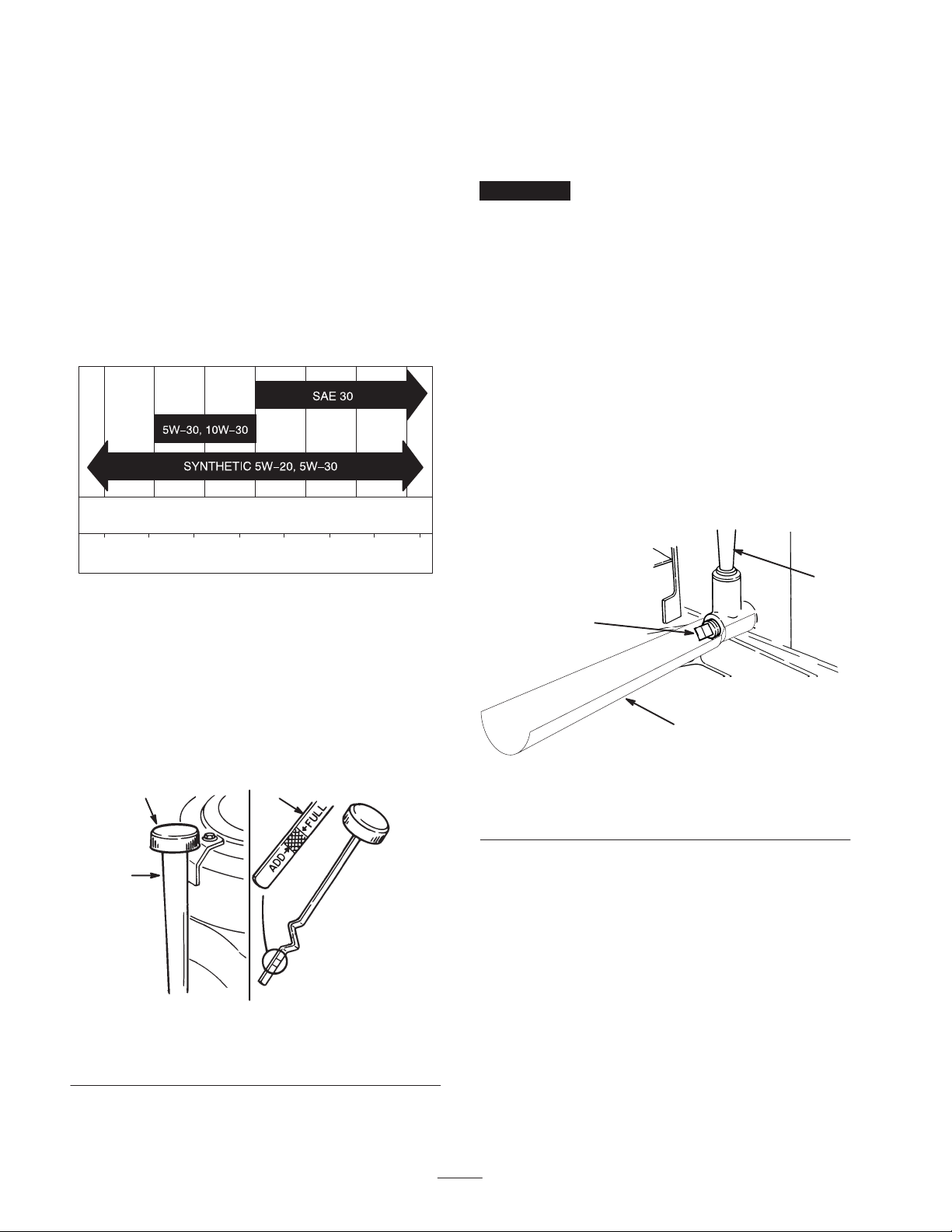
5. Screw the oil dipstick fully onto the filler tube (Fig. 14).
Unscrew the dipstick again and look at the metal end. If
the oil level is low, slowly pour only enough oil into the
filler tube to raise the level to the Full mark on the
dipstick.
Important Do not overfill the crankcase with oil
because the engine may be damaged.
Oil Type: Detergent oil (API service SF, SG, SH, SJ, or
higher)
Crankcase Capacity: 48 oz./1-1/2 qt. (1400 cc/1.4 l)
Viscosity: See the table below.
USE THESE SAE VISCOSITY OILS
–200 20406080100
°
F
–30°–20 –10 0 10 20 30 40
C
Checking the Oil Level
1. Park the machine on a level surface, disengage the PTO,
set the parking brake, stop the engine, and remove the
ignition key.
Changing and Draining the Oil
1. Start the engine and let it run for five minutes. This
warms the oil so that it drains better.
2. Park the machine so that the right front side is slightly
lower than the left side to ensure that the oil drains
completely. Then disengage the PTO, set the parking
brake, stop the engine, and remove the ignition key.
3. Raise the seat.
4. Slide the draining funnel underneath the oil dipstick/fill
tube (Fig. 15).
5. Place a pan below the oil dipstick/fill tube and remove
the drain plug (Fig. 15).
2
1
2. Raise the seat.
3. Clean around the oil dipstick (Fig. 14) so that dirt
cannot fall into the filler hole and damage the engine.
1
2
3
m–1868
Figure 14
1. Oil dipstick
2. Metal end
3. Filler tube
4. Unscrew the oil dipstick and wipe the metal end clean
(Fig. 14).
3
m–5977
Figure 15
1. Oil drain plug
2. Oil dipstick/fill tube
3. Draining funnel
6. When the oil has drained completely, install the drain
plug.
Note: Dispose of the used oil at a certified recycling center.
7. Slowly pour approximately 80% of the specified
amount of oil into the filler tube (Fig. 14). Check the oil
level; refer to Checking the Oil Level, page 20,
steps 4–5.
20
Page 21
Servicing the Battery
Always keep the battery clean and fully charged. Use a
paper towel to clean the battery and battery box. If the
battery terminals are corroded, clean them with a solution
of four parts water and one part baking soda. Apply a light
coating of grease to the battery terminals to prevent
corrosion.
Voltage: 12 v, 155 Cold Cranking Amps
Removing the Battery
Warning
Battery terminals or metal tools could short
against metal tractor components causing sparks.
Sparks can cause the battery gasses to explode,
resulting in personal injury.
• When removing or installing the battery, do not
allow the battery terminals to touch any metal
parts of the tractor.
• Do not allow metal tools to short between the
battery terminals and metal parts of the tractor.
Installing the Battery
1. Put the battery into the battery box in the chassis.
2. Using the bolt, washers, and nut, connect the positive
(red) cable to the positive (+) battery post. Slide the
rubber cover over the battery post.
3. Using the bolt, washers, and nut, connect the negative
(black) cable to the negative (–) battery post.
4. Install the engine cover.
Checking the Electrolyte Level
Danger
Battery electrolyte contains sulfuric acid which is a
deadly poison and causes severe burns.
• Do not drink electrolyte and avoid contact with
skin, eyes or clothing. Wear safety glasses to
shield your eyes and rubber gloves to protect
your hands.
• Fill the battery where clean water is always
available for flushing the skin.
1. Disengage the PTO, set the parking brake, stop the
engine, and remove the ignition key.
2. Remove the engine cover.
3. Disconnect the negative (black) ground cable from the
battery post.
Warning
Incorrect battery cable routing could damage the
tractor and cables causing sparks. Sparks can
cause the battery gasses to explode, resulting in
personal injury.
• Always disconnect the negative (black) battery
cable before disconnecting the positive (red)
cable.
• Always connect the positive (red) battery cable
before connecting the negative (black) cable.
4. Slide the rubber cover up the positive (red) cable.
Disconnect the positive (red) cable from the battery
post.
5. Remove the battery from the battery box.
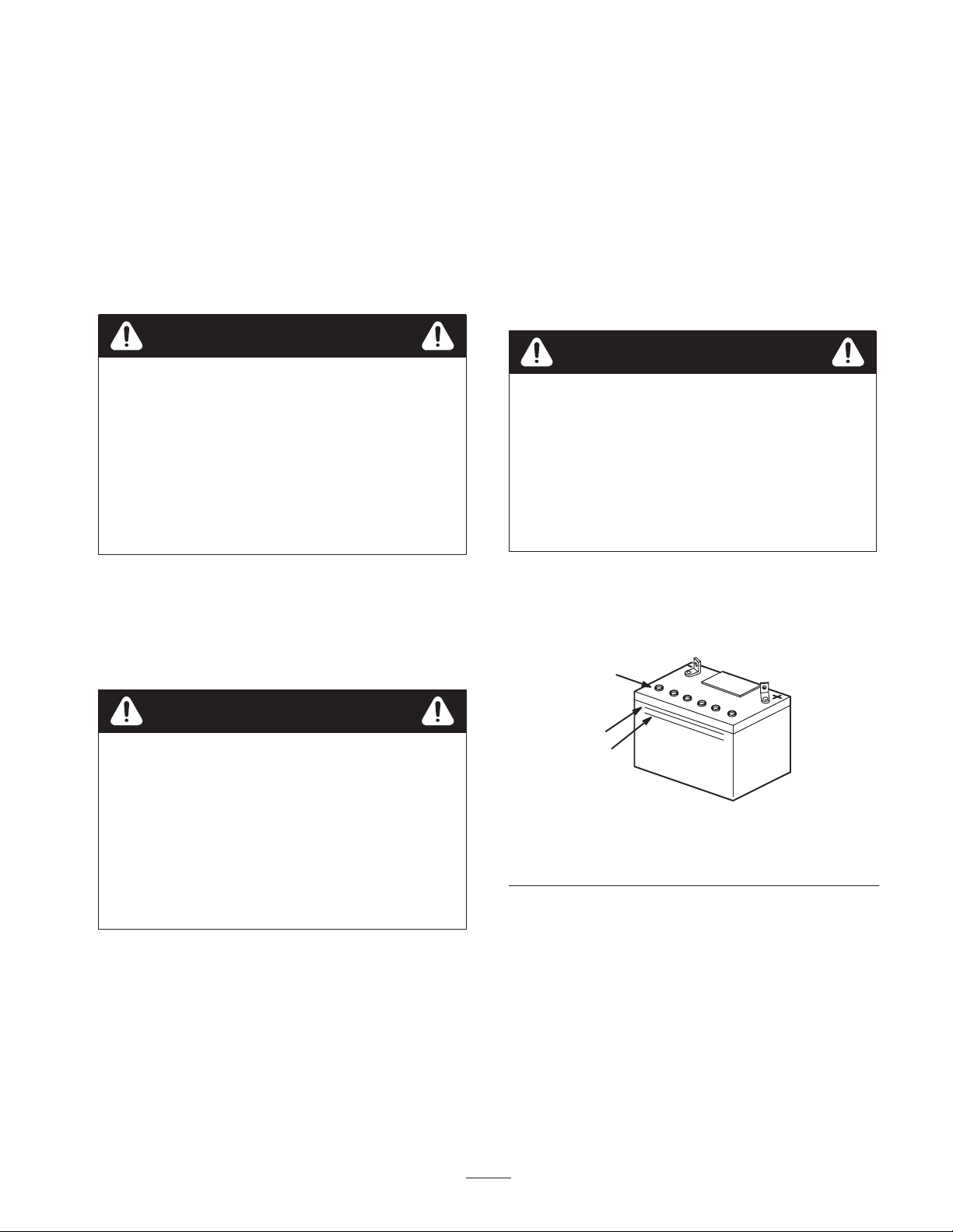
1. Remove the engine cover.
2. Look at the side of the battery. The electrolyte must be
up to the Upper line (Fig. 16). Do not allow the
electrolyte to fall below the Lower line (Fig. 16).
1
2
3
m-5004
Figure 16
1. Vent caps
2. Upper line
3. If the electrolyte is low, add the required amount of
distilled water; refer to Adding Water to the Battery,
page 22.
3. Lower line
21
Page 22
Adding Water to the Battery
The best time to add distilled water to the battery is just
before you operate the machine. This lets the water mix
thoroughly with the electrolyte solution.
1. Remove the battery from the tractor; refer to Removing
the Battery, page 21.
2. Clean the top of the battery with a paper towel.
Important Never fill the battery with distilled water
while the battery is installed in the tractor. Electrolyte could
be spilled on other parts and cause corrosion.
3. Remove the vent caps from the battery (Fig. 16).
4. Slowly pour distilled water into each battery cell until
the electrolyte level is up to the Upper line (Fig. 16) on
the battery case.
Charging the Battery
Warning
Charging the battery produces gasses that can
explode.
Never smoke near the battery and keep sparks and
flames away from battery.
Important Always keep the battery fully charged
(1.260 specific gravity). This is especially important to
prevent battery damage when the temperature is below
32°F (0°C).
1. Remove the battery from the chassis; refer to Removing
the Battery, page 21.
Important Do not overfill the battery because
electrolyte (sulfuric acid) can cause severe corrosion and
damage to the chassis.
5. Wait five to ten minutes after filling the battery cells.
Add distilled water, if necessary, until the electrolyte
level is up to the Upper line (Fig. 16) on the battery
case.
6. Install the battery vent caps.
2. Check the electrolyte level; refer to Checking the
Electrolyte Level, page 21.
3. Make sure that the vent caps are installed in the battery.
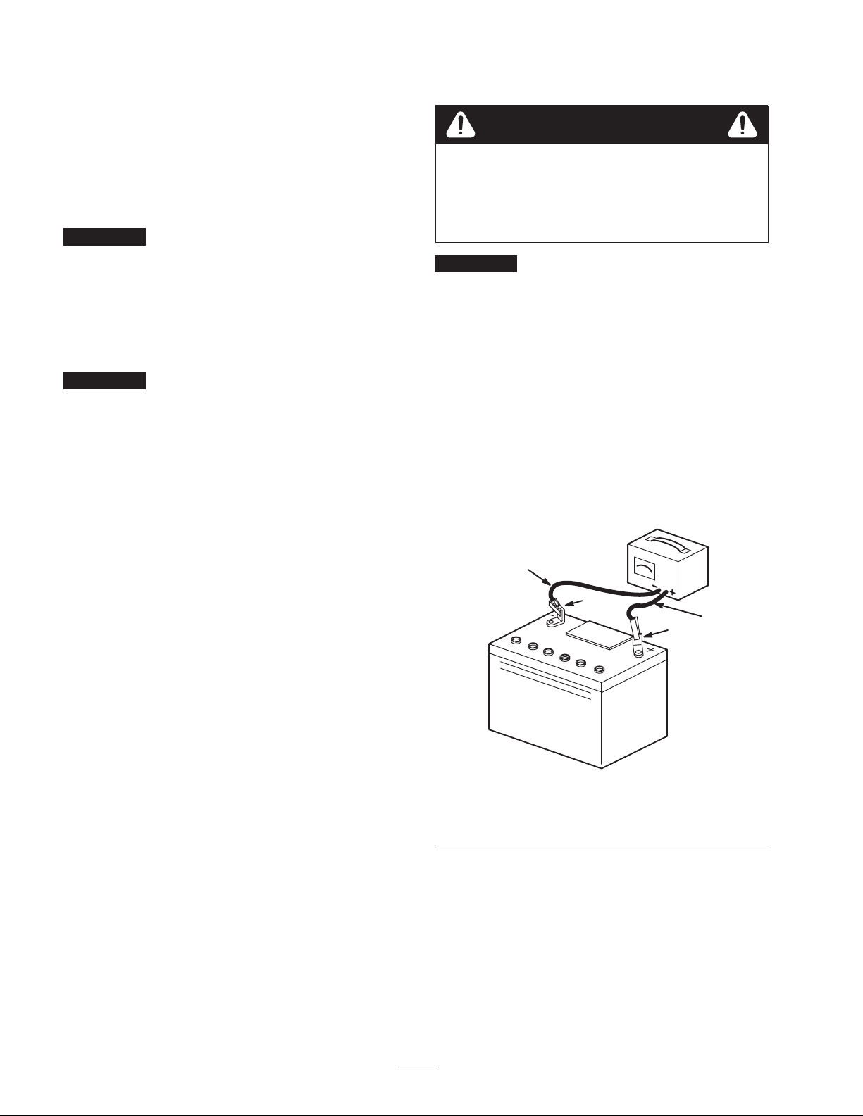
Charge the battery for 1 hour at 25 to 30 amps or 6
hours at 4 to 6 amps. Do not overcharge the battery.
4. When the battery is fully charged, unplug the charger
from the electrical outlet, then disconnect the charger
leads from the battery posts (Fig. 17).
4
2
3
1
m–4970
Figure 17
1. Positive battery post
2. Negative battery post
3. Red (+) charger lead
4. Black (–) charger lead
5. Install the battery in the tractor and connect the battery
cables; refer to Installing the Battery, page 21.
Note: Do not run the tractor with the battery disconnected.
Electrical damage may occur.
22
Page 23
Servicing the Air Cleaner
Foam Element: Clean and oil after every 25 operating
hours.
Paper Element: Replace after every 100 operating hours or
yearly, whichever occurs first.
Note: Service the air cleaner more frequently (every few
hours) if operating conditions are extremely dusty or sandy.
Removing the Foam and Paper Elements
1
2
1. Disengage the PTO, set the parking brake, stop the
engine, and remove the ignition key.
2. Remove the engine cover.
3. Clean around the air cleaner to prevent dirt from getting
into the engine and causing damage. Unscrew the knob
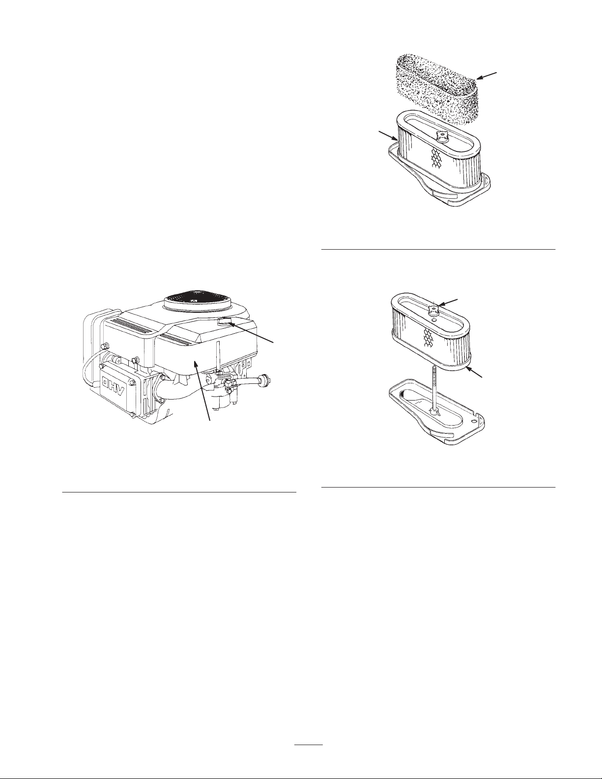
and remove the air cleaner cover (Fig. 18).
1
2
m–1884
Figure 18
1. Knob 2. Air cleaner cover
m–1864
Figure 19
1. Foam element 2. Paper element
5. Unscrew the rubber nut and remove the paper element
(Fig. 20).
1
2
m–1865
Figure 20
1. Rubber nut 2. Paper element
4. Carefully slide the foam element off of the paper
element (Fig. 19).
23
Page 24
Cleaning the Foam and Paper Elements
Installing the Foam and Paper Elements
1. Foam Element
A. Wash the foam element in liquid soap and warm
water. When the element is clean, rinse it
thoroughly.
B. Dry the element by squeezing it in a clean cloth.
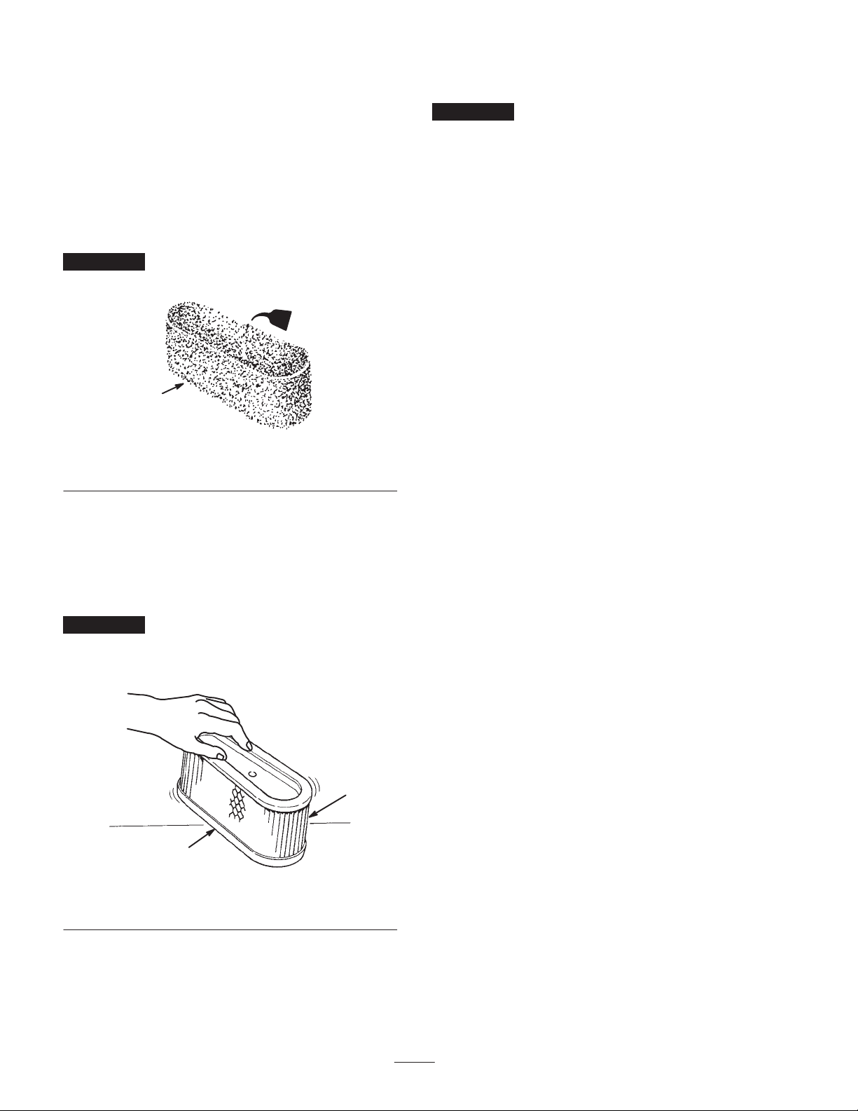
C. Put one or two ounces of oil on the element
(Fig. 21). Squeeze the element to distribute the oil.
Important Replace the foam element if it is torn or
worn.
2
1
Figure 21
1. Foam element 2. Oil
2. Paper Element
Important To prevent engine damage, always operate
the engine with the complete foam and paper air cleaner
assembly installed.
1. Carefully slide the foam element onto the paper air
cleaner element (Fig. 19).
2. Slide the air cleaner assembly onto the long rod. Screw
the rubber nut finger-tight against the air cleaner
(Fig. 20).
Note: Make sure that the rubber seal is flat against the air
cleaner base.
3. Install the air cleaner cover and knob (Fig. 18). Tighten
the knob snugly.
4. Install the engine cover.
m–1866
A. Lightly tap the element on a flat surface to remove
dust and dirt (Fig. 22).
B. Inspect the element for tears, an oily film, and
damage to the rubber seal.
Important Never clean the paper element with
pressurized air or liquids, such as solvent, gas, or kerosene.
Replace the paper element if it is damaged or cannot be
cleaned thoroughly.
1
2
m–1867
Figure 22
1. Paper element 2. Rubber seal
24
Page 25
Servicing the Spark Plug
2
3
Install a new spark plug after every 100 operating hours.
Check the spark plug after every 25 operating hours. Make
sure that the air gap between the center and side electrodes
is correct before installing the spark plug. Use a spark plug
wrench for removing and installing the spark plug and a
gapping tool/feeler gauge to check and adjust the air gap.
Type: Champion RJ-19LM (or equivalent)
Air Gap: 0.030 in. (0.762 mm)
Removing the Spark Plug
1. Disengage the PTO, set the parking brake, stop the
engine, and remove the ignition key.
2. Reach under the body of the tractor above the left rear
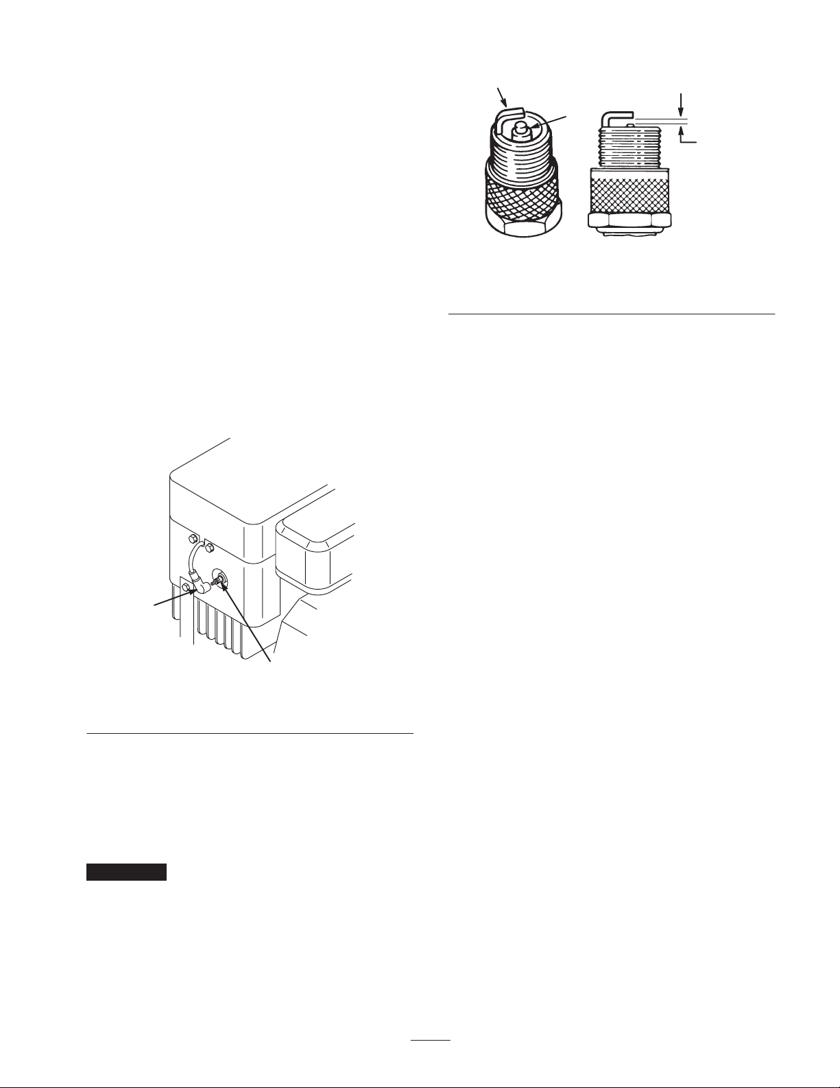
wheel and pull the wire off of the spark plug (Fig. 23).
Clean around the spark plug to prevent dirt from falling
into the engine and potentially causing damage.
3. Remove the spark plug and metal washer.
1
0.030 in.
(0.762 mm)
m–1870
Figure 24
1. Center electrode insulator
2. Side electrode
3. Air gap (not to scale)
Installing the Spark Plug
1. Install the spark plug and metal washer. Make sure that
the air gap is set correctly.
2. Tighten the spark plug to 15 ft.-lb. (20 N⋅m).
3. Push the wire onto the spark plug (Fig. 23).
Checking the Tire Pressure
1
m–18842
Figure 23
1. Spark plug wire 2. Spark plug
Checking the Spark Plug
1. Look at the center of the spark plug (Fig. 24). If you see
light brown or gray on the insulator, the engine is
operating properly. A black coating on the insulator
usually means the air cleaner is dirty.
Important Never clean the spark plug. Always replace
the spark plug when it has a black coating, worn electrodes,
an oily film, or cracks.
2. Check the gap between the center and side electrodes
(Fig. 24). Bend the side electrode (Fig. 24) if the gap is
not correct.
Maintain the air pressure in the front tires at 150 kPa and in
the rear ties at 200 kPa. Check the tire pressure after each
use. Check the tires when they are cold to get the most
accurate pressure reading.
Greasing and Lubrication
Grease the machine after every 25 operating hours or once
a year, whichever occurs first. Grease more frequently
when operating conditions are extremely dusty or sandy.
Grease Type: General-purpose grease
1. Disengage the PTO, set the parking brake, stop the
engine, and remove the ignition key.
2. Lubricate the front wheels.
3. Wipe up any excess grease.
Checking the Parking Brake
Always set the parking brake when you stop the machine or
leave it unattended. Check the parking brake daily to ensure
that it holds securely.
1. Park the machine on a level surface, disengage the PTO,
set the parking brake, stop the engine, and remove the
ignition key.
25
Page 26
2. If the rear wheels lock and skid when you try to push
the tractor forward, no adjustment is required. If the
rear wheels turn and do not lock, an adjustment is
needed; see an Authorized Service Dealer.
Draining the Fuel Tank
Replacing the Fuel Filter
Replace the fuel filter after every 100 operating hours or
yearly, whichever occurs first.
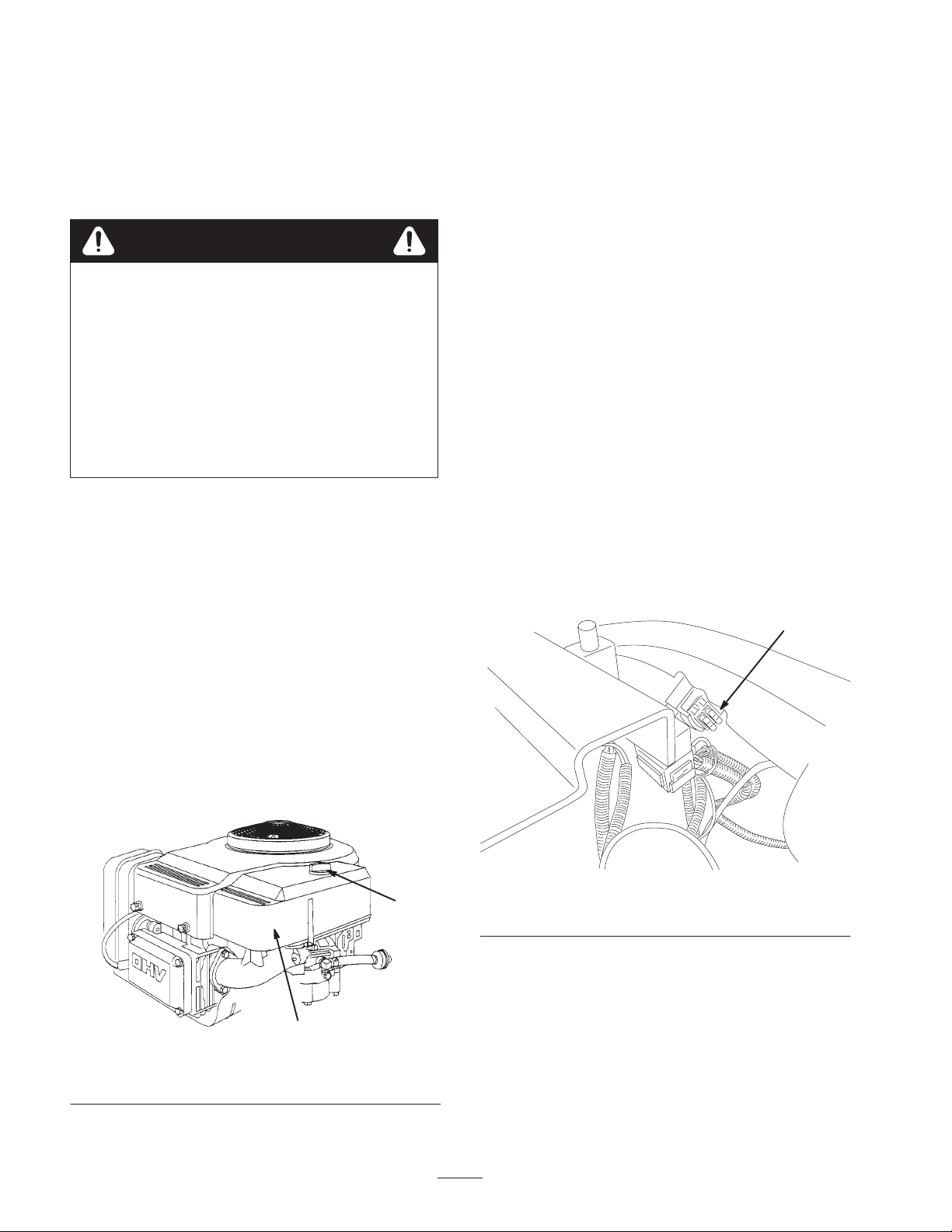
The best time to replace the fuel filter (Fig. 25) is when the
fuel tank is empty. Never install a dirty filter if it is
removed from the fuel line.
Danger
In certain conditions, gasoline is extremely
flammable and highly explosive. A fire or
explosion from gasoline can burn you and others
and can damage property.
• Drain gasoline from the fuel tank when the
engine is cold. Do this outdoors in an open area.
Wipe up any gasoline that spills.
• Never smoke when draining gasoline, and stay
away from an open flame or where a spark may
ignite the gasoline fumes.
1. Park the machine so that the left side is slightly lower
than the right side to ensure that the fuel tank drains
completely. Disengage the PTO, set the parking brake,
stop the engine, and remove the ignition key.
2. Remove the engine cover.
3. Squeeze the ends of the hose clamp together and slide it
up the fuel line toward the fuel tank.
4. Pull the fuel line off of the filter (Fig. 25) and allow
gasoline to drain into a gas can or drain pan.
1. Disengage the PTO, set the parking brake, stop the
engine, and remove the ignition key.
2. Remove the engine cover.
3. Squeeze the ends of the hose clamps together and slide
them away from the filter (Fig. 25).
4. Remove the filter from the fuel lines.
5. Install a new filter and move the hose clamps close to
the filter.
6. Install the engine cover.
Servicing the Fuses
The electrical system is protected by fuses. No maintenance
is required, however, if a fuse blows, check the circuit
wiring for a short. To replace a fuse (Fig. 26), pull up to
remove it from the socket. Push down to insert it.
Fuses: 7.5 amp, blade-type
1
Note: Now is the best time to install a new fuel filter
because the fuel tank is empty.
5. Install the fuel line onto the filter. Slide the hose clamp
close to the filter to secure the fuel line and filter.
6. Install the engine cover.
1
2
Figure 25
1. Fuel filter
m–1884
m–5970
Figure 26
1. Fuses (under the seat)
26
Page 27
Servicing the Cutting Blade
To ensure a superior quality of cut, keep the blade sharp.
For convenient sharpening and replacement, you may want
to have an extra blade.
Danger
A worn or damaged blade can break, and a piece
of the blade could be thrown into the operator’s or
bystander’s area, resulting in serious personal
injury or death.
• Inspect the blade periodically for wear or
damage.
• Replace a worn or damaged blade.
Inspecting the Blade
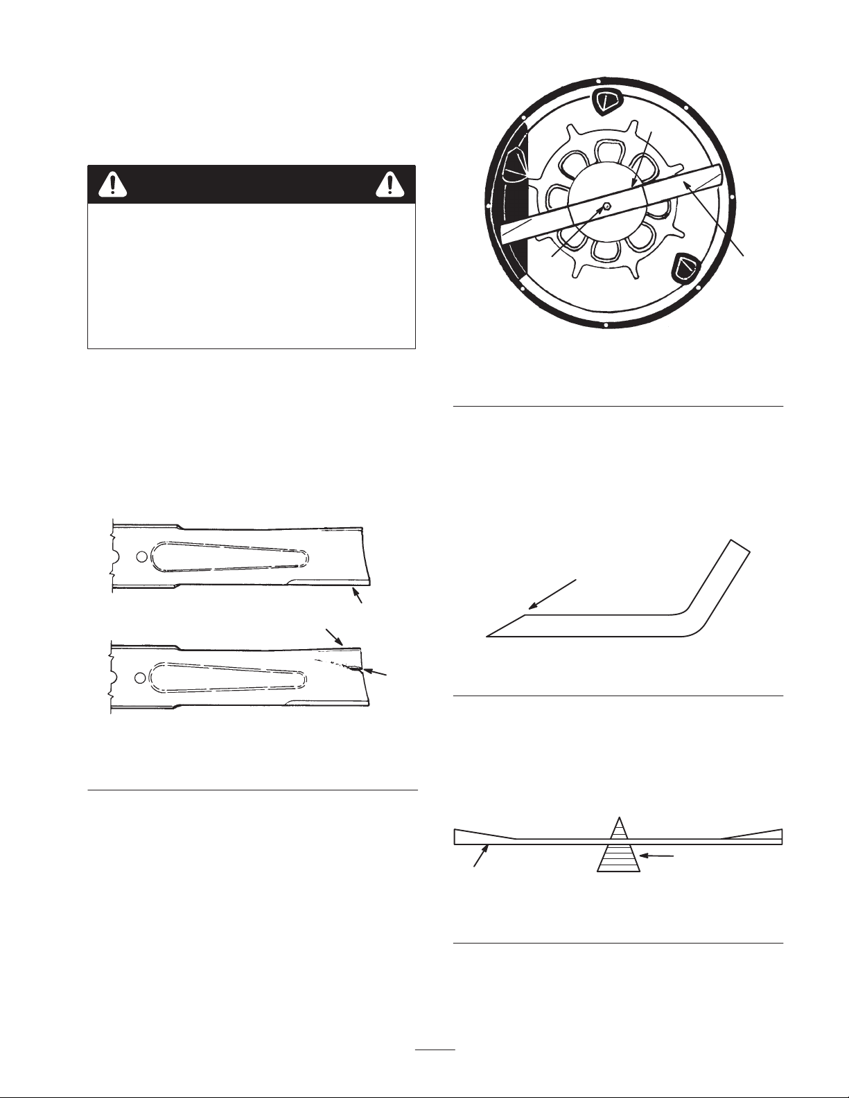
1. Inspect the cutting edges (Fig. 27). If the edges are not
sharp or have nicks, remove the blade and sharpen
them; refer to Sharpening the Blade, page 27.
2. Inspect the blade, especially the curved area (Fig. 27). If
you notice any damage, wear, or a slot forming in this
area (Fig. 27), immediately install a new blade.
2
3
1
Figure 28
1. Blade
2. Blade stiffener
3. Blade bolt and curved
washer
Sharpening the Blade
1. Use a file to sharpen the cutting edge at both ends of the
blade (Fig. 29). Maintain the original angle. The blade
retains its balance if the same amount of material is
removed from both cutting edges.
2
1
3
m–151
Figure 27
1. Cutting edge
2. Curved area
3. Wear/slot forming
Removing the Blade
1. Stop the engine and remove the ignition key. Pull the
wire off of the spark plug.
2. Engage the parking brake.
3. Grasp the end of the blade using a rag or thickly padded
glove. Then remove the blade bolt, curved washer,
blade stiffener, and blade (Fig. 28). A block of wood
may be wedged between the blade and the mower to
lock the blade when you are removing the bolt.
1
m–1854
Figure 29
1. Sharpen at original angle
2. Check the balance of the blade by putting it on a blade
balancer (Fig. 30). If the blade stays in a horizontal
position, the blade is balanced and can be used. If the
blade is not balanced, file some metal off of the back
side of the blade. Repeat this procedure until the blade
is balanced.
2
1
Figure 30
1. Blade 2. Balancer
27
Page 28
Installing the Blade
1. Iinstall the blade, blade stiffener, curved washer, and
blade bolt (Fig. 28).
Important The curved part of the blade must be
pointing toward the inside of the mower to ensure proper
cutting.
2. Tighten the blade bolt to 45–60 ft.-lb. (61–81 N⋅m)
Important Make sure the cutting edge of the blade is
away from the mower housing.
Leveling the Mower
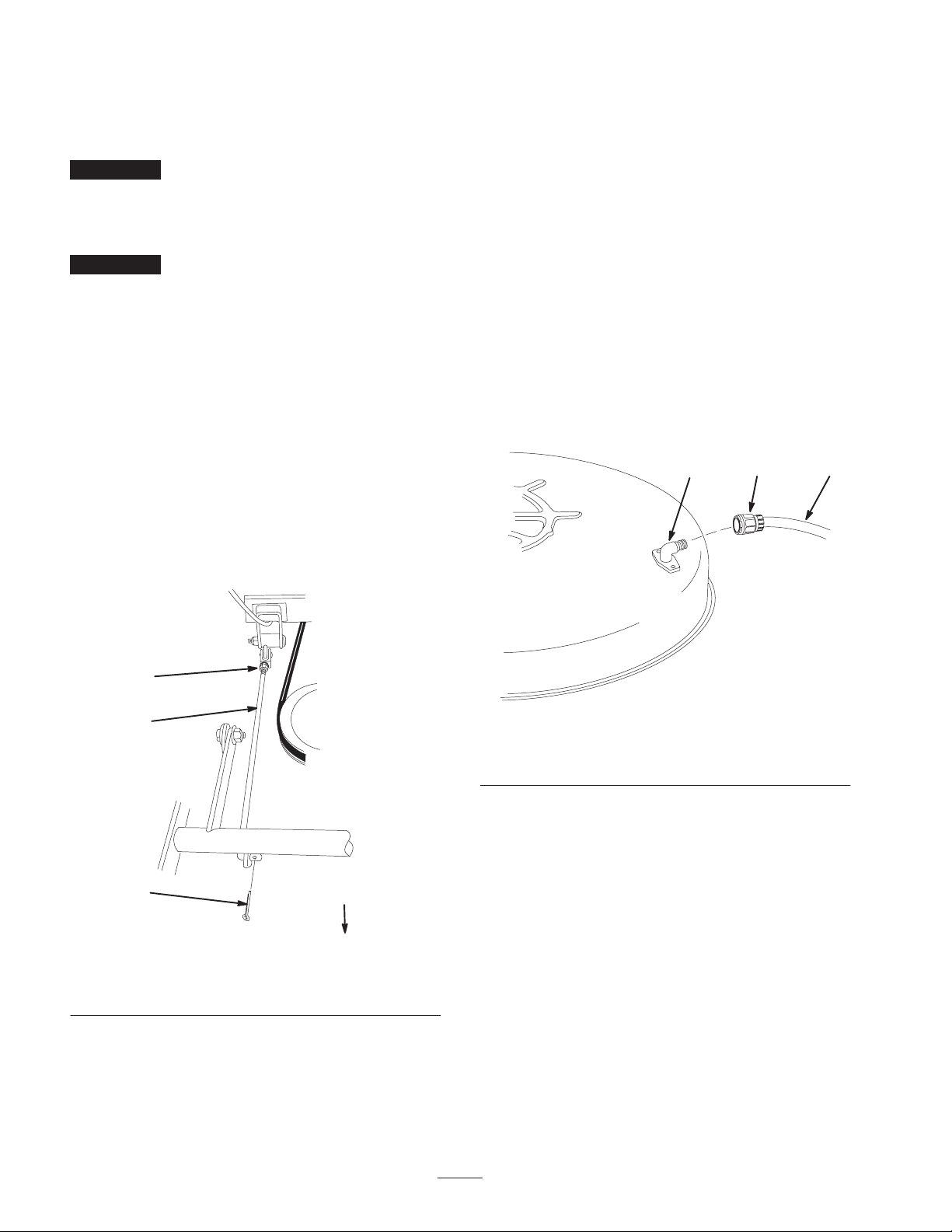
5. Loosen the nut at the rear of the adjusting rod (Fig. 31).
6. Turn the adjusting rod to the desired deck level.
7. Tighten the nut and install the cotter pin.
Washing the Underside of the
Mower
After each use, wash the underside of the mower to prevent
grass buildup for improved mulch action and clipping
dispersal.
1. Park the machine on a hard level surface, disengage the
PTO, stop the engine, and remove the ignition key.
If the mower cuts unevenly and the cutting blade is not
bent, then the mower must be leveled.
1. Place the tractor on level surface, engage the parking
brake, stop the engine, and remove the ignition key.
2. Pull the wire off of the spark plug.
3. Set the air pressure in the front and rear ties to the
recommended inflation; refer to Checking the Tire
Pressure, page 25.
4. Remove the cotter pin at the front of the adjusting rod
(Fig. 31).
3
1
2. Attach the hose coupling to the end of the mower
washout fitting, and turn the water on high (Fig. 32).
Note: Spread petroleum jelly on the washout fitting o-ring
to make the coupling slide on easier and protect the o-ring.
1
Figure 32
1. Washout port
2. Coupling
3. Lower the mower to the lowest height-of-cut.
3. Hose
2
3
m–3118
2
1. Adjusting rod
2. Cotter pin
Figure 31
3. Nut
front of mower
m–5976
4. Sit on the seat and start the engine. Engage the PTO and
let the mower run for one to three minutes.
5. Disengage the PTO, stop the engine, and remove the
ignition key. Wait for all moving parts to stop.
6. Turn the water off and remove the hose coupling from
the washout fitting.
Note: If the mower is not clean after one washing, soak it
and let it stand for 30 minutes. Then repeat the process.
7. Run the mower again for one to three minutes to
remove excess water.
28
Page 29

Warning
7. For storage over 30 days, prepare the traction unit as
follows:
A broken or missing washout fitting could expose
you and others to thrown objects or blade contact.
Contact with blade or thrown debris contact will
cause injury or death.
• Replace broken or missing washout fitting
immediately, before using mower again.
• Plug any hole(s) in mower with bolts and
locknuts.
• Never put your hands or feet under the mower
or through openings in the mower.
Washing the Machine
1. Stop the engine and remove the ignition key. Wait
10–15 minutes for the engine to cool down.
2. Wash the machine with mild detergent and water.
Important Do not use a pressure washer to wash the
machine. Pressure washing may damage the electrical
system or wash away necessary grease at friction points.
Avoid excessive use of water, especially near the control
panel, lights, engine, and battery.
3. Start the engine to dry it off.
Cleaning and Storage
1. Disengage the PTO, set the parking brake, stop the
engine, and remove the ignition key.
2. Remove grass clippings, dirt, and grime from the
external parts of the entire machine, especially the
engine. Clean dirt and chaff from the outside of the
engine cylinder head fins and blower housing.
Important You can wash the machine with mild
detergent and water. Do not use a pressure washer to
wash the machine. Pressure washing may damage the
electrical system or wash away necessary grease at friction
points. Avoid excessive use of water, especially near the
control panel, lights, engine, and battery.
3. Check the brake; refer to Checking the Parking Brake,
page 25.
4. Service the air cleaner; refer to Servicing the Air
Cleaner, page 23.
5. Change the crankcase oil; refer to Servicing the Engine
Oil, page 20.
6. Check the tire pressure; refer to Checking the Tire
Pressure, page 25.
A. Add a petroleum based stabilizer/conditioner to fuel
in the tank. Follow the mixing instructions from the
stabilizer manufacturer (1 oz. per gallon). Do not
use an alcohol based stabilizer (ethanol or
methanol).
Note: A fuel stabilizer/conditioner is most effective
when mixed with fresh gasoline and used at all times.
B. Run the engine to distribute conditioned fuel
through the fuel system (5 minutes).
C. Stop the engine, allow it to cool, and drain the fuel
tank; refer to Draining the Fuel Tank, page 26.
D. Restart the engine and run it until it stops.
E. Choke or prime the engine.
F. Start and run the engine until it will not start again.
Use the primer, if equipped on the machine, several
times to ensure that no fuel remains in the primer
system.
G. Dispose of fuel properly. Recycle as per local codes.
Important Do not store stabilizer/conditioned gasoline
over 90 days.
8. Remove the spark plug(s) and check its condition; refer
to Servicing the Spark Plug, page 25. With the spark
plug(s) removed from the engine, pour two tablespoons
of engine oil into the spark plug hole. Use the electric
starter to crank the engine and distribute the oil inside
the cylinder. Install the spark plug(s); refer to Spark
Plug, page 25. Do not install the wire on the spark
plug(s).
9. Disconnect the negative battery cable. Clean the battery
and battery terminals. Check the electrolyte level and
charge it fully; refer to Servicing the Battery, page 21.
Leave the negative battery cable disconnected from the
battery during storage.
Important The battery must be fully charged to prevent
it from freezing and being damaged at temperatures below
32°F (0°C). A fully charged battery can be stored one
winter season without recharging.
10.Check and tighten all bolts, nuts, and screws. Repair or
replace any part that is worn or damaged.
11. Paint all scratched or bare metal surfaces. Paint is
available from your Authorized Service Dealer.
12.Store the machine in a clean, dry garage or storage area.
Remove the ignition and KeyChoice keys from the
mower and keep them in a memorable place. Cover the
machine to protect it and keep it clean.
29
Page 30
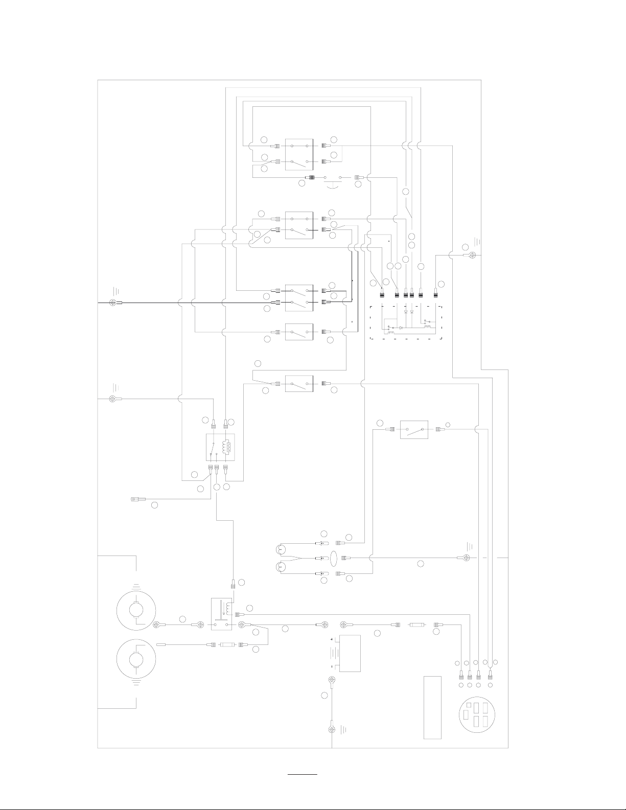
Wiring Diagram
GND
BLACK
GND
BLACK
GREY
GREY
GREY
K1
S2
(PTO)
SHOWN WITH
TURQ./BLACK
17
S6
(REVERSE)
SHOWN
TURQ./BLACK
S5
(BRAKE)
PTO DISENGAGED
IN NEUTRAL
26
35
BRAKE DISENGAGED
SHOWN WITH
10
5
32
36
35
RED/BLACK
18
S3
KEY SWITCH
MOMENTARY
(OVER RIDE)
GREY/BLACK
GREY/BLACK
TURQ./BLACK
RED
19
TURQ./BLACK
15
16
RED/BLACK
TURQUOISE
TURQUOISE
RED
11
12
11
RED
BROWN
26
18
5
462
ORANGE
13
1
BLACK
3
GND
31
31
TURQ./BLACK
TURQUOISE
TURQUOISE
11
16
17
15
34
12
37
GREY
34 33
S8
BROWN
10
14
ORANGE
BLACK
28
3
(KILL RELAY)
BROWN
13
1
2
5
4
S4
(SEAT)
SHOWN
IN NEUTRAL
(FORWARD)
ON THE SEAT
SHOWN WHEN
OPERATOR IS NOT
36
NMIR MODULE
BROWN
7
TURQUOISE
20
S7
(BAG FULL)
SWITCH CLOSES
BAG IS FULL
WHEN GRASS
MICRO SWITCH BAG FULL
6
RED/BLACK
STARTER
ALTERNATOR
MAGNET
GND
SM
AM
GND
33
14
30
29
GREY
29
4
RED
RED
SOLENOID
WHITE/BLACK
30
9
2
2
RED LAMP
(OVER RIDE)
(BAG FULL)
ORANGE LAMP
RED
3
ORANGE
RED
WHITE
WHITE
WHITE
25
22
7.5A F1
GREY
1
BLACK
23+24
GND
19
20
12V DC
BATTERY
RED
BLACK
ORANGE
RED
21
BLACK
27
8
7.5A F2
8
S1
KEY SWITCH
(IGNITION)
ON B I A AND
OFF NO CONNECTION
X Y
START B I S
GND
ORANGE
TURQUOISE
RED/WHITE
7
9
BAS
I
S
X
Y
RED/BLACK
RED/BLACK
6
5
I
BA
30
Page 31

Troubleshooting
g
g
Problem Possible Causes Corrective Action
The starter does not crank.
The engine will not start, starts
hard, or fails to keep running.
1. The blade control (PTO) is
Engaged.
2. The parking brake is not on. 2. Set the parking brake.
3. The battery is dead. 3. Charge the battery.
4. The electrical connections are
corroded or loose.
5. A fuse is blown. 5. Replace the fuse.
6. A relay or switch is damaged. 6. Contact an Authorized Service
1. The operator is not seated. 1. Sit on the seat.
2. The fuel tank is empty. 2. Fill the fuel tank with gasoline.
3. The air cleaner is dirty. 3. Clean or replace the air cleaner
4. The spark plug wire is loose or
disconnected.
5. The spark plug is pitted, fouled,
or the gap is incorrect.
6. The choke is not closing. 6. Adjust the throttle cable.
7. There is dirt in the fuel filter. 7. Replace the fuel filter.
1. Move the PTO to Disengaged.
4. Check the electrical
connections for good contact.
Dealer.
element.
4. Install the wire on the spark
plug.
5. Install a new, correctly-gapped
spark plug.
The engine loses power.
8. The idle speed is too low or the
mixture is incorrect.
9. Dirt, water, or stale fuel is in the
fuel system.
10.The engine is flooded. 10.Remove the spark plug and dry
11.The battery is dead. 11.Charge the battery.
1. The engine load is excessive. 1. Reduce ground speed.
2. The air cleaner is dirty. 2. Clean the air cleaner element.
3. The oil level in the crankcase is
low.
4. The cooling fins and air
passages under the engine
blower housing are plugged.
5. The spark plug is pitted, fouled,
or the gap is incorrect.
6. There is dirt in the fuel filter. 6. Replace the fuel filter.
7. Dirt, water, or stale fuel is in the
fuel system.
8. Adjust the carburetor idle
speed and idle mixture.
9. Contact an Authorized Service
Dealer.
it.
3. Add oil to the crankcase.
4. Remove the obstruction from
the cooling fins and air
passages.
5. Install a new, correctly-gapped
spark plug.
7. Contact an Authorized Service
Dealer.
31
Page 32

Problem Corrective ActionPossible Causes
g
gg
g
The engine overheats.
There is an abnormal vibration.
The blade does not rotate.
The machine does not drive.
1. The engine load is excessive. 1. Reduce ground speed.
2. The oil level in the crankcase is
low.
3. The cooling fins and air
passages under the engine
blower housing are plugged.
1. The cutting blade is bent or
unbalanced.
2. The blade mounting bolt is
loose.
3. The engine mounting bolts are
loose.
4. There is a loose engine pulley,
idler pulley, or blade pulley
5. The engine pulley is damaged. 5. Contact an Authorized Service
1. The blade drive belt is worn,
loose, or broken.
2. The blade drive belt is off of the
pulley.
1. The traction belt is worn, loose,
or broken.
2. Add oil to the crankcase.
3. Remove the obstruction from
the cooling fins and air
passages.
1. Install a new cutting blade.
2. Tighten the blade mounting
bolt.
3. Tighten the engine mounting
bolts.
4. Tighten the appropriate pulley.
Dealer.
1. Contact an Authorized Service
Dealer.
2. Contact an Authorized Service
Dealer.
1. Contact an Authorized Service
Dealer.
The cutting height is uneven.
The cutting quality is poor.
The grass collector fails to fill.
2. The traction belt is off of the
pulley.
3. The drive control is in the Push
position.
1. The tire pressure is incorrect. 1. Set the tire pressure.
2. The mower is not level. 2. Level the mower.
3. The underside of the mower is
dirty.
1. The cutting blade is worn. 1. Sharpen or replace the cutting
2. The cutting height is incorrect. 2. Adjust the cutting height.
1. The cutting height is too low. 1. Raise the cutting height.
2. The grass is too heavy or
damp.
3. The cutting blade is worn. 3. Sharpen or replace the cutting
4. The grass is too high. 4. Raise the cutting height.
5. The discharge area is blocked. 5. Remove the obstruction from
2. Contact an Authorized Service
Dealer.
3. Move the drive control to the
Operate position.
3. Clean the underside of the
mower.
blade.
2. Wait until the grass has dried.
blade.
the discharge area.
32
 Loading...