

Toro 70125 Parts Catalogue
Wheel Horse13–32G
Rear Engine Rider
Model No. 70125–220000001 and Up
Form No. 3327–642
Parts Catalog
Ordering Replacement Parts
To order replacement parts, please supply: the part
number, the quantity, and the description of each
part desired.
Understanding Reference Numbers
Each identified part in an illustration has a reference
number. The reference number for a part also appears in
the parts list, along with other information about the part.
This catalog uses two special reference number formats,
one to indicate parts in a service assembly and another
to indicate the quantity of a given part in an illustration.
Service Assembly Reference Numbers
Parts in service assemblies have reference numbers in
the form a:b.
the entire service assembly and the b represents a
sequential number unique to each part within the service
assembly.
The a represents the reference number of
The TORO Company — 2002
All Rights Reserved
For example, a wheel assembly might be identified by
reference number 6, the tire by 6:1, the valve by 6:2,
and the wheel by 6:3. When you order the assembly
identified by reference number 6, you receive all parts
identified by reference numbers 6:1, 6:2, and 6:3.
However, you may also order any part individually.
Reference numbers of this type appear in illustrations
and in part lists.
Reference Numbers Indicating Quantity
In an illustration, if a reference number indicates more
than one part, the reference number has the form nX y.
The n represents the quantity of the part, the X is the
multiplication symbol, and the y represents the reference
number.
For example, in an illustration, the reference number
2X 37 means that two of the parts identified by reference
number 37 are indicated.

3327–642
Contents
Description Page Description Page
Body and Decal Assembly 3. . . . . . . . . . . . . . . . . . . .
Seat and Rear Bag Assembly 4. . . . . . . . . . . . . . . . .
Front Axle and Steering Assembly 5. . . . . . . . . . . . .
Deck and Spindle Assembly 6. . . . . . . . . . . . . . . . . .
Deck Suspension Assembly 8. . . . . . . . . . . . . . . . . .
Rear Wheel Assembly 9. . . . . . . . . . . . . . . . . . . . . . .
Engine and Fuel Tank Assembly 10. . . . . . . . . . . . .
Gear Transmission and Linkage Assembly 11. . . . .
Electrical and Cable Assembly 12. . . . . . . . . . . . . . .
Cover Assembly
Peerless No. MST205–542D 13. . . . . . . . . . . . . . . . .
Case Assembly
Peerless No. MST–542D 14. . . . . . . . . . . . . . . . . . . .
Case Assembly (continued)
Peerless No. MST205–542D 15. . . . . . . . . . . . . . . . .
Cylinder Assembly
Engine Briggs and Stratton Model
28M707–1127–E1 16. . . . . . . . . . . . . . . . . . . . . . . . . .
Crankshaft Assembly
Engine Briggs and Stratton Model
28M707–1127–E1 17. . . . . . . . . . . . . . . . . . . . . . . . . .
Crankshaft Assembly (continued)
Engine Briggs and Stratton Model
28M707–1127–E1 18. . . . . . . . . . . . . . . . . . . . . . . . . .
Crankcase Assembly
Engine Briggs and Stratton Model
28M707–1127–E1 19. . . . . . . . . . . . . . . . . . . . . . . . . .
Carburetor Assembly
Engine Briggs and Stratton Model
28M707–1127–E1 20. . . . . . . . . . . . . . . . . . . . . . . . . .
Air Cleaner Assembly
Engine Briggs and Stratton Model
28M707–1127–E1 21. . . . . . . . . . . . . . . . . . . . . . . . . .
Muffler and Fuel Tank Assembly
Engine Briggs and Stratton Model
28M707–1127–E1 22. . . . . . . . . . . . . . . . . . . . . . . . . .
Governor Assembly
Engine Briggs and Stratton Model
28M707–1127–E1 23. . . . . . . . . . . . . . . . . . . . . . . . . .
Blower Housing Assembly
Engine Briggs and Stratton Model
28M707–1127–E1 24. . . . . . . . . . . . . . . . . . . . . . . . . .
Starter Assembly
Engine Briggs and Stratton Model
28M707–1127–E1 25. . . . . . . . . . . . . . . . . . . . . . . . . .
Gasket Assembly
Engine Briggs and Stratton Model
28M707–1127–E1 26. . . . . . . . . . . . . . . . . . . . . . . . . .
Carburetor Overhaul Kit Assembly
Engine Briggs and Stratton Model
28M707–1127–E1 27. . . . . . . . . . . . . . . . . . . . . . . . . .
Part Description Abbreviations
Part descriptions in this catalog may include the following abbreviations.
Abbreviation Meaning Abbreviation Meaning
AR as required. . . . . . . . . . . . . . . . .
ASM assembly. . . . . . . . . . . . . . . .
CARR carriage. . . . . . . . . . . . . .
DEG degrees. . . . . . . . . . . . . . . .
FH flat head. . . . . . . . . . . . . . . . .
GA gauge. . . . . . . . . . . . . . . . .
HF hex flange. . . . . . . . . . . . . . . . .
HH hex head. . . . . . . . . . . . . . . . .
HHF hex head flange. . . . . . . . . . . . . . . .
HLH hex lag head. . . . . . . . . . . . . . . .
HJ hex jam. . . . . . . . . . . . . . . . . .
HOC height-of-cut. . . . . . . . . . . . . . . .
HS hex socket. . . . . . . . . . . . . . . . .
HSBH hex socket button head. . . . . . . . . . . . . .
HSFH hex socket flat head. . . . . . . . . . . . . . .
HSH hex socket head. . . . . . . . . . . . . . . .
HWH hex washer head. . . . . . . . . . . . . . .
HWHTF hex washer head. . . . . . . . . . . . .
thread forming
HYD hydraulic. . . . . . . . . . . . . . . .
INC incorporated. . . . . . . . . . . . . . . . .
LH left hand. . . . . . . . . . . . . . . . .
NI nylon insert. . . . . . . . . . . . . . . . . .
PPH Phillips pan head. . . . . . . . . . . . . . . .
PTH Phillips truss head. . . . . . . . . . . . . . . .
PTO power take off. . . . . . . . . . . . . . . .
RH right hand. . . . . . . . . . . . . . . . .
SFH slotted fillister head. . . . . . . . . . . . . . . .
SHH slotted hex head. . . . . . . . . . . . . . . .
SQH square head. . . . . . . . . . . . . . . .
SHWH slotted hex washer head. . . . . . . . . . . . . .
SPH slotted pan head. . . . . . . . . . . . . . . .
SRH slotted round head. . . . . . . . . . . . . . . .
STD standard. . . . . . . . . . . . . . . .
TAP self tapping. . . . . . . . . . . . . . . .
TTH Torx truss head. . . . . . . . . . . . . . . .
WH wing head. . . . . . . . . . . . . . . . .
2
4:2
25
24
22
14
21
20
19
27
26
18
17
3327–642
1
2X 2
3
4
5
4:1
7
16
15
29
31
3X 2
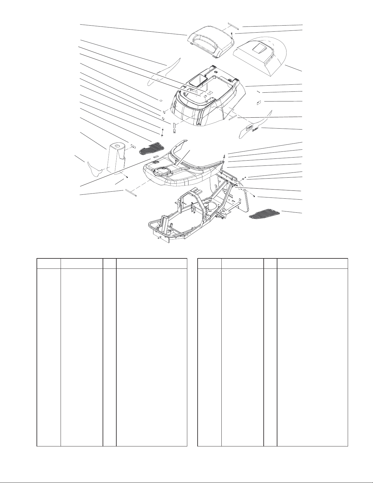
Body and Decal Assembly
DescriptionPart No. Qty.Ref. No. DescriptionPart No. Qty.Ref. No.
1 105–0537 1 Decal–Logo,
Wheelhorse
2 106–2851 13 Screw–HH, TAP
3 106–1810 1 Cover– Grass Bag
4 106–2885 1 Shroud And Decal
ASM
4:1 1 Decal–Danger
4:2 1 Decal–Warning, Hot
5 106–2870 2 Pin–Dowel
7 1 Decal–Shift
8 106–1800 1 Decal–Shroud
9 49–7810 5 Nut–Lock
10 106–2853 8 Washer–Flat
11 106–2901 1 Foot Rest And Decals
ASM
11:2 1 Decal–Caution
12 33113–020 2 Screw–HH
13 106–2973 1 Floormat–LH
14 1 Decal–Clutch,Int’l Rer
15 105–0528 1 Decal–Steering
Column
16 106–2906 1 Steering–Turret
17 1 Decal–Run Lights
18 106–2972 1 Floormat–RH
19 1 Decal–HOC
11:2
8
2X 9
2X 10
11
12
3X 9
6X 10
30
8X 2
13
Sheet No.:2
20 1 Decal–PTO,
Disengage
21 1 Decal–PTO, Engage
22 1 Decal–Nmir
24 106–1801 1 Decal–Shroud
25 106–2860 1 Cover–Engine
26 106–2854 1 Washer–Flat
27 46–0330 1 Nut–Lock
29 106–2987 1 Cover
30 33113–016 1 Screw–HH
31 106–6509 1 Decal–Toro Intl Rer
* 106–2887 1 Kit–Decals
Not serviced separately
* Not illustrated
3
3327–642
12
11
18
10
4X 6
2X 7
9
15
23
8
7
4X 6
14
13
2X 15
16
17
19
8
1
2
20
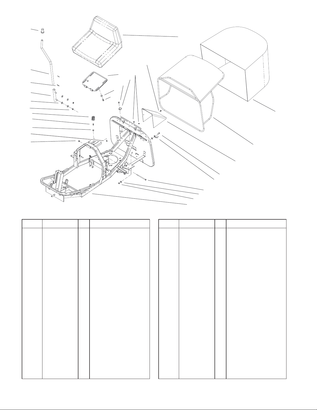
Seat and Rear Bag Assembly
DescriptionPart No. Qty.Ref. No. DescriptionPart No. Qty.Ref. No.
1 106–2867 1 Bag–Grass
2 106–2924 1 Frame–Bag
3 33114–020 1 Screw–HH
4 106–2969 1 Hook–Bag
5 106–1844 1 Screw–HH
6 106–2854 10 Washer–Flat
7 46–0330 4 Nut–Lock
8 49–7810 4 Nut–Lock
9 106–2945 1 Spring–Compression
10 106–2927 1 Support
11 106–2928 1 Lever
12 106–2903 1 Knob
13 106–2944 1 Plate–Seat
14 33104–016 4 Screw–HHF
15 33113–016 3 Screw–HH
16 106–2929 2 Clip
17 106–2857 1 Seat
18 106–2871 2 Pin–Spring
19 33103–012 1 Screw–HHF
20 105–8947 1 Deflector–Rear
Discharge
21 106–1815 1 Frame
23 106–2865 1 Washer–Flat
21
3
4
5
2X 6
7
Sheet No.:3
4
10
30
29
34
41
27
26
25
4X 12
4X 21
24
2X 21
2X 20
23
28
13
35
32
36
12
37
38
16
17
18
19
2X 20
2X 21
22
12
13
14
15
4X 2
39
40
11
10
3327–642
1
2
4
3
5
8
42
Sheet No.:4
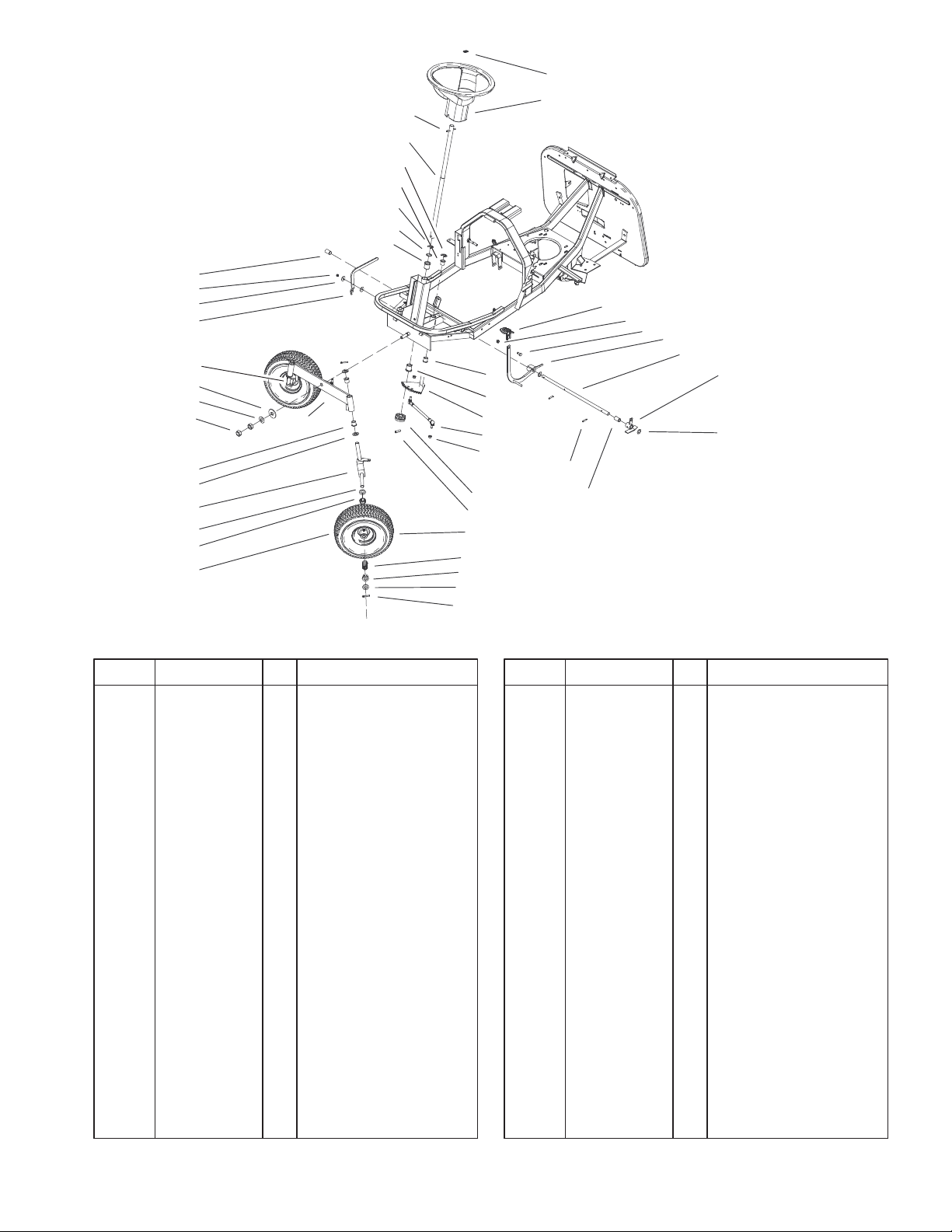
Front Axle and Steering Assembly
DescriptionPart No. Qty.Ref. No. DescriptionPart No. Qty.Ref. No.
1 106–2957 1 Pedal–Brake
2 46–0330 6 Nut–Lock
3 106–2935 1 Lever–Clutch
4 33114–020 1 Screw–HH
5 106–2985 1 Shaft
8 106–2978 1 Bushing
10 106–2962 2 Bushing
11 106–2874 2 Pin–Dowel
12 106–1811 6 Bushing
13 106–2873 2 Bushing
14 106–2868 1 Rack–Steering
15 106–2933 2 Rod–Tie
16 106–2878 1 Gear–Steering
17 106–1845 1 Pin–Spiral
18 106–2951 2 Wheel
19 106–6507 2 Bearing
20 106–6508 4 Bushing
21 33098–00 8 Washer–Flat
22 3272–21 4 Pin–Cotter
23 106–2907 2 Tire
24 106–2953 1 Axle–Wheel,LH
25 33018–00 2 Nut–Hex
26 106–2926 1 Washer–Bell
27 106–2925 1 Washer–Flat
28 106–2864 1 Axle–Front
29 106–2853 2 Washer–Flat
30 49–7810 1 Nut–Lock
32 106–1807 1 Spacer
34 106–2961 1 Lever
35 106–2909 1 Ring–Retaining,Ext
36 106–2908 1 Ring–Retaining,Ext
37 106–2872 1 Shaft–Steering
38 106–1846 1 Pin–Roll
39 106–2883 1 Wheel–Steering
40 98–1459 1 Decal–Toro
41 106–2952 1 Axle–Wheel,RH
42 106–1835 3 Spacer
5
3327–642
43
42
50
21
41
40
39
38
8X 22
37
8X 25
36
35
33
34
32
29
22
21:3
44 25
30
31
46
47 48
4X 22
21:2
23
7
4X 25
20
15
14
19
10
12
51
11
13
1
52
3
4
5
6
8
9
2
49
14
16
17
18
45
28
27
26
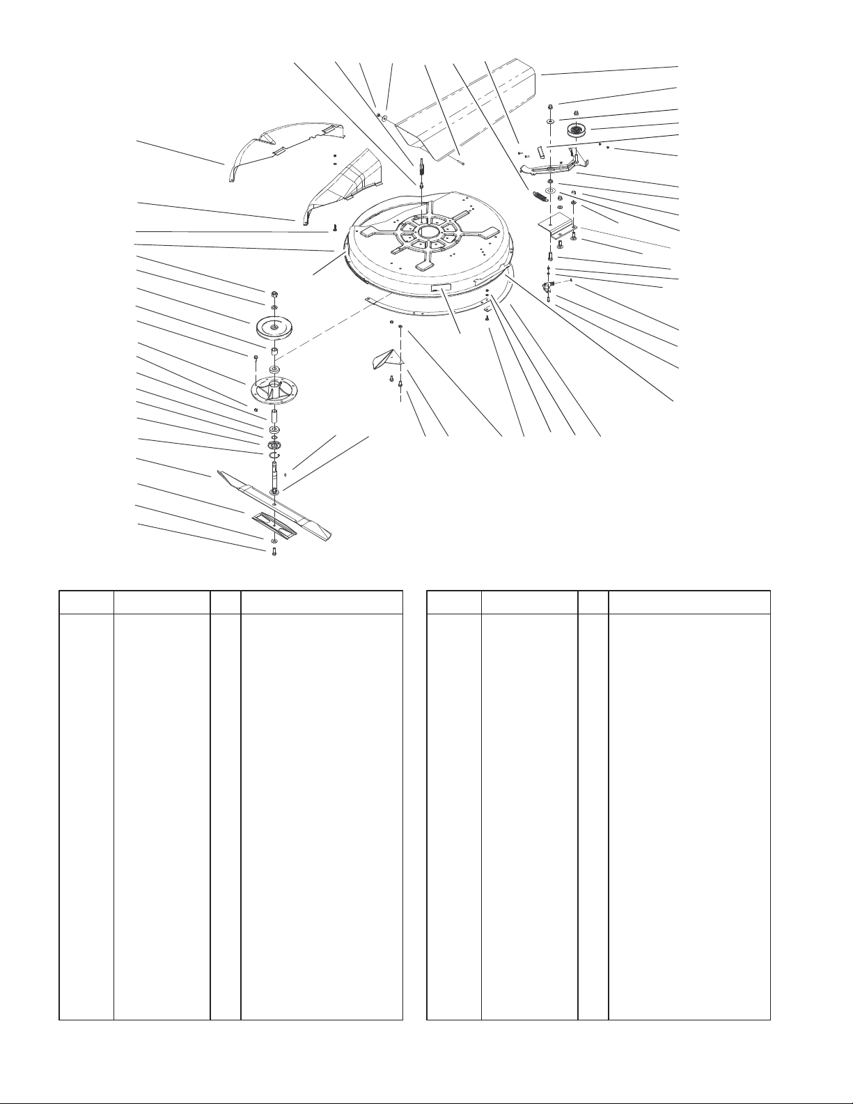
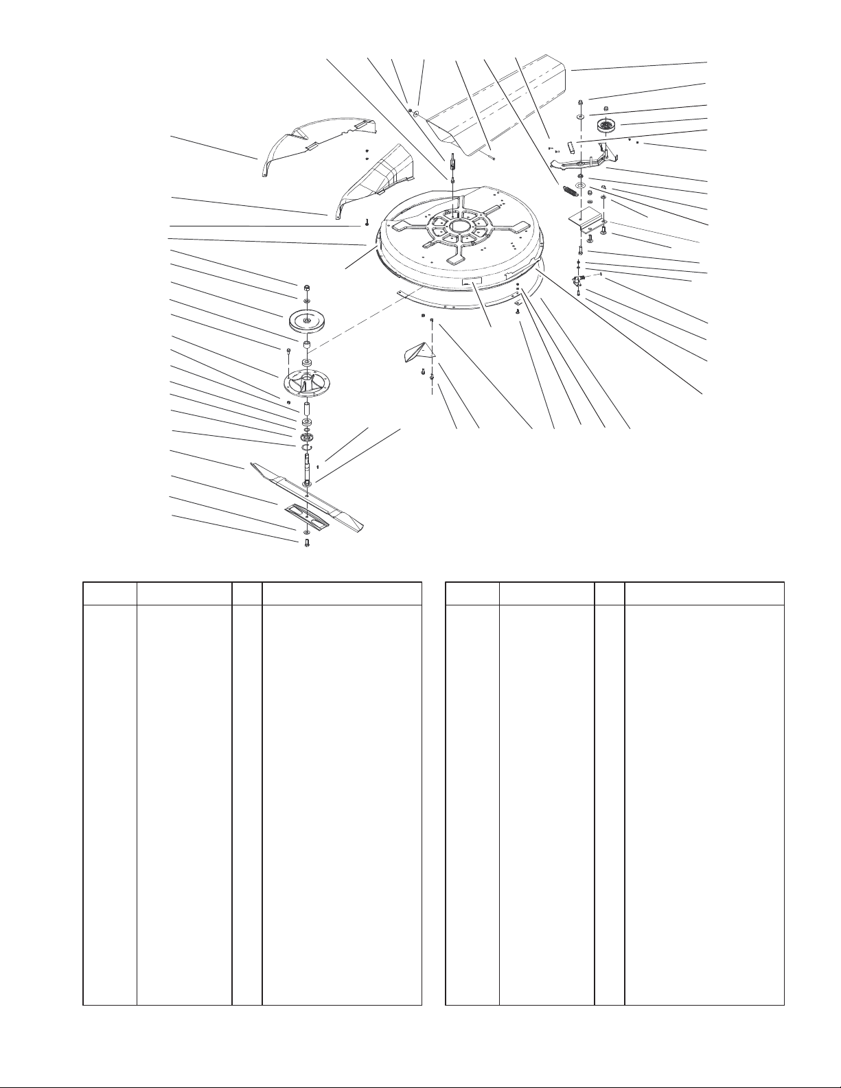
Deck and Spindle Assembly
DescriptionPart No. Qty.Ref. No. DescriptionPart No. Qty.Ref. No.
1 106–2970 1 Tube–Discharge
2 46–0090 2 Nut–Lock
3 106–2922 1 Washer–Flat
4 106–1813 1 Pulley–Idler
5 106–1814 1 Brake–Rubber
6 46–0410 2 Nut–Lock
7 60–6910 2 Screw
8 106–2889 1 Brake ASM
9 106–2892 1 Bushing
10 33096–00 2 Washer–Flat
11 106–2884 1 Bracket–Deck
12 33126–035 2 Screw–CARR
13 33116–035 1 Screw–HH
14 49–7810 11 Nut–Lock
15 33093–00 9 Washer–Flat
16 106–1847 1 O–Ring
17 95–2747 1 Fitting–Washout
18 106–6515 2 Screw–Hfh
19 80–4490 4 Ring–32in Deck
20 106–6510 5 Screw–Sh
21 106–2900 1 Deck And Decals ASM
21:2 1 Decal–Caution
21:3 1 Decal–Discharge
Cover
22 33104–020 13 Screw–HHF
23 80–2630 2 Kicker
Sheet No.:5
25 46–0330 13 Nut–Lock
26 3212–5 1 Screw–HH
27 106–2858 1 Washer–Bell
28 80–4570 1 Stiffener
29 105–0526 1 Blade – 32in
29 80–4430 1 Blade–Recycler
30 106–1805 1 Key
31 106–2902 1 Shaft–Spindle
32 106–2910 1 Ring–Snap
33 106–1807 1 Spacer
34 80–4370 1 Shield – Bearing
35 251–297 2 Bearing
36 106–2888 1 Spacer
37 56–7030 1 Spindle
38 106–1842 1 Spacer
39 106–1812 1 Pulley
40 33098–00 1 Washer–Flat
41 106–2914 1 Nut–Hex
42 106–2898 1 Tunnel–Discharge
43 106–2899 1 Cover–Recycler
44 106–2897 1 Guide–Belt
45 105–0536 1 Decal–Deck
46 106–2855 1 Washer–Flat
47 33114–030 1 Screw–HH
48 106–1838 1 Spring–Extension
49 106–2893 1 Spacer
Not serviced separately
6
43
42
50
21
41
40
39
38
8X 22
37
8X 25
36
35
33
34
32
29
22
21:3
44 25
30
31
46
47 48
4X 22
21:2
23
7
4X 25
20
15
14
19
10
12
51
11
13
1
52
3
4
5
6
8
9
2
49
14
16
17
18
45
3327–642
28
27
26
Deck and Spindle Assembly
DescriptionPart No. Qty.Ref. No. DescriptionPart No. Qty.Ref. No.
50 106–2890 4 Screw–Sh
51 106–2865 2 Washer–Flat
52 106–6513 2 Nut–Lock
Sheet No.:5
7
3327–642
10
9
26
25
24
23
27
32
4
1
2
3
34
29
28
31
30
10
5
11
6
7
8
10
11
12
13
10
14
15
16
17
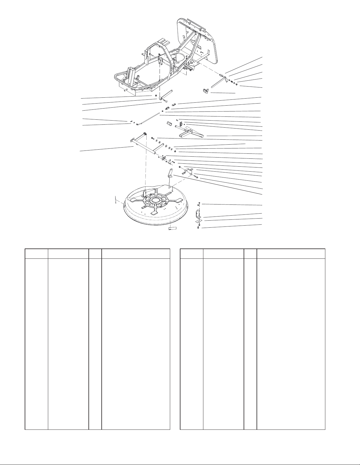
Deck Suspension Assembly
DescriptionPart No. Qty.Ref. No. DescriptionPart No. Qty.Ref. No.
1 106–1809 1 Retainer–Yoke
2 106–1803 1 Yoke
3 33014–00 1 Nut–Hex
4 106–2937 1 Rod–Tie
5 106–2880 3 Bracket–Support
6 106–2966 1 Lever–Lift
7 33115–035 3 Screw–HH
8 106–6511 6 Washer–Flat
9 106–1829 1 Hanger Deck ASM
10 33025–00 5 Nut–Lock
11 49–7810 8 Nut–Lock
12 106–2865 4 Washer–Flat
13 33113–035 4 Screw–HH
14 106–2895 1 Bracket–Deck
15 106–2912 1 Bushing
16 33115–050 1 Screw–HH
17 106–2894 1 Bracket–Deck
18 46–0330 10 Nut–Lock
19 106–2896 2 Bracket–Deck
20 33104–020 10 Screw–HHF
23 33094–00 1 Washer–Flat
24 106–2879 1 Pin–Hair
25 106–2882 1 Screw–CARR
26 106–1830 1 Hanger Deck ASM
27 106–2967 2 Handle
28 106–2954 1 Lever–Blade,Clutch
18
19
33
20
Sheet No.:6
29 106–2955 1 Bushing
30 106–2869 3 Shim
31 106–2950 1 Spring–Compression
32 106–1806 9 Washer
33 106–6512 1 Plate
34 33113–016 4 Screw–HH
8

23
3327–642
3
4
7
8
9
24
26
21
Rear Wheel Assembly
DescriptionPart No. Qty.Ref. No. DescriptionPart No. Qty.Ref. No.
3 33116–035 1 Screw–HH
4 106–2877 1 Pulley ASM
7 106–6513 1 Nut–Lock
8 106–2921 1 Washer–Flat
9 33025–00 1 Nut–Lock
13 106–2948 1 Wheel–LH
14 106–2913 2 Tire
15 106–2994 2 Key–Square
17 106–2909 2 Ring–Retaining,Ext
19 106–2992 2 Washer–Flat
21 33114–060 4 Screw–HH
23 46–0330 4 Nut–Lock
24 106–2947 1 Wheel–RH
26 33094–00 4 Washer–Flat
19
13
14
15
17
Sheet No.:7
9
 Loading...