

Page 1

13-32
Rear Engine Rider
Model Nos. 70125 and 70184
Loose Parts
Description Qty. Use
Form No. 3329-321
Setup Instructions
Wheels
Flat washers, M16 (3 mm thick)
Spacers, M16 (1 mm thick)
Cotter pins
Seat
Screws, M8 x 18 mm
Flat washers, M9
Lock washers
Socket pin 1 Attaching the steering wheel
Engine cover
Screws, M6 x 25 mm
Frame
Fabric bag with clips
Handle
Locknuts, M8
Washers, M9
Z-brackets
Bolts, M6 x 16.2 mm
Nuts, M6
Grass collector cover
Pins
Full bag lever
2
2
4
2
1
4
4
4
1
2
1
1
1
2
4
2
2
2
1
2
1
Installing the front wheels
Installing the seat
Installing the engine cover
Assembling the grass collector
Installing the grass collector
Bolts, M6 x 20 mm
Flat washers, M6.5
Nuts, M6
Recycler cover 1
Draining funnel 1 Draining the engine oil
Keys 2
Operator’s Manual
Engine operator’s manual
2002 by The Toro Company
8111 Lyndale Avenue South
Bloomington, MN 55420-1196
2
4
2
1
1
Installing the battery
Recycling the grass clippings; refer to the
tractor
Using the keys in the ignition and KeyChoice
switches
Reading before operating the tractor.
Operator’s Manual
1
All Rights Reserved
Printed in Italy
Page 2
Assembling the Tractor
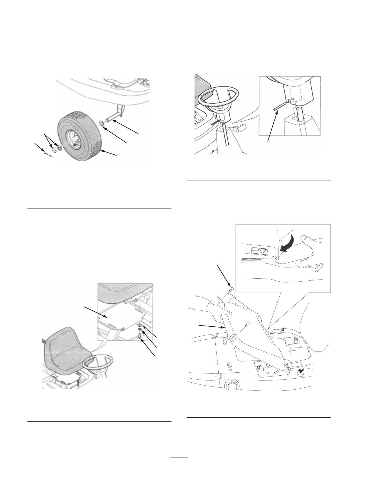
Installing the Front Wheels
1. Slide a flat washer (M16, 3mm thick) onto each spindle
(Fig. 1).
Attaching the Steering Wheel
1. Rotate the steering wheel upward until it is aligned with
the steering column.
2. Secure the steering wheel with the socket pin (Fig. 3).
4
5
1
3
2
Figure 1
1. Spindle
2. Wheel
3. Flat washer
(M16, 3 mm thick)
4. Spacers
(M16, 1 mm thick)
5. Cotter pin
2. Mount the wheels and secure each of them with
2 spacers (M16, 1 mm thick) and a cotter pin (Fig. 1).
3. Grease the wheels.
Installing the Seat
Attach the seat to the support plate with 4 flat washers
(M9), lock washers, and screws (M8 x 18 mm) (Fig. 2).
1
1
Figure 3
1. Socket pin
Installing the Engine Cover
1. Slide the tabs on the engine cover into the slots on the
body of the tractor (Fig. 4).
2
Figure 2
1. Seat Support plate
2. Flat washer (M9)
3. Lock washer
4. Screw (M8 x 18 mm)
Note: Before tightening the screws, adjust the seat to a
position that is most comfortable for you.
1
2
3
4
m–5980
Figure 4
1. Engine cover 2. Screw
2. Secure the cover with 2 screws (M6 x 25 mm) (Fig. 4).
2
Page 3

Assembling the Grass Collector
1. Slide the bag onto the frame and secure it with the clips
(Fig. 5).
1
2
Figure 5
1. Bag 2. Frame
2. Secure the handle to the bag assembly with 4 washers
(M9) and 2 locknuts (M8) (Fig. 6).
1
4
5
3
1
2
m-6101
Figure 7
1. Rear panel
2. Switch
3. Switch plate
4. Full bag lever
5. Screw
2. Hold the switch plate against the switch and slide the full
bag lever into the rectangular slot on the rear panel.
3. Hook the switch plate onto the lever and secure the
switch and switch plate to the rear panel with the 2
screws (Fig. 7).
4. Attach the grass collector to the rear of the tractor with
2 Z-brackets, bolts (M6 x 16.2 mm), and nuts (M6)
(Fig. 8).
1
3
4
2
4
3
Figure 6
1. Bag assembly
2. Handle
3. Washer (M9)
4. Locknut (M8)
Installing the Grass Collector
1. Reach beneath the rear of the tractor and hold the full
bag switch and switch plate while removing the 2
screws on the rear panel (Fig. 7).
2
Figure 8
1. Grass collector
2. Z-bracket
3. Bolt (M6 x 16.2 mm)
4. Nut ( M6)
5. Attach the grass collector cover to the tractor with
2 pins (Fig. 9).
1
2
2
Figure 9
1. Grass collector cover 2. Pin
3
Page 4

Activating the Battery
Purchase bulk electrolyte with 1.260 specific gravity from a
local battery supply outlet.
7. Charge the battery for 1 hour at 25 to 30 amps or
6 hours at 4 to 6 amps. Do not overcharge the battery.
Warning
Danger
Battery electrolyte contains sulfuric acid, a deadly
poison that can cause severe burns.
• Do not drink electrolyte and avoid contact with
skin, eyes or clothing. Wear safety glasses to
shield your eyes and rubber gloves to protect
your hands.
• Fill the battery where clean water is always
available for flushing the skin.
• Follow all instructions and comply with all
safety messages on the electrolyte container.
1. Remove the battery from the tractor and place it on a
level surface; refer to Removing the Battery in the
Operator’s Manual.
Important Never fill the battery with electrolyte while
the battery is installed in the tractor. You could spill
electrolyte on other parts and cause corrosion.
2. Clean the top of the battery with a paper towel.
3. Remove the vent caps from the battery (Fig. 10).
Charging the battery produces gasses that can
explode.
Never smoke near the battery and keep sparks and
flames away from battery.
8. When the battery is fully charged, unplug the charger
from the electrical outlet, then disconnect the charger
leads from the battery posts (Fig. 11).
4
1. Positive post
2. Negative post
2
Figure 11
3. Charger red (+) wire
4. Charger black (–) wire
3
1
1
2
3
m5004
Figure 10
1. Vent caps
2. Upper line
4. Slowly pour electrolyte into each battery cell until the
electrolyte level is up to the Upper line on the battery
case (Fig. 10).
Important Do not overfill the battery because
electrolyte (sulfuric acid) can severely corrode and damage
the chassis.
5. Wait 5 to 10 minutes after filling the battery cells, then
add electrolyte, if necessary, until the electrolyte level is
up to the upper line (Fig. 10) on the battery case.
6. Install the battery vent caps.
3. Lower line
9. Install the battery in the tractor and connect the battery
cables; refer to Installing the Battery in the Operator’s
Manual.
Checking the Engine Oil Level
Before you start the engine and use the tractor, check the oil
level in the engine crankcase; refer to Checking the Oil
Level in the Operator’s Manual.
Filling the Fuel Tank
Add fuel to the fuel tank; refer to Filling the Fuel Tank in
the Operator’s Manual.
Checking the Tire Pressure
Check the front and rear tires for proper inflation; refer to
Checking the Tire Pressure in the Operator’s Manual.
Testing the Safety System
Test the safety interlock system; refer to The Safety
Interlock System in the Operator’s Manual.
4
 Loading...