

Page 1
Introduction
The 690 Series Rotary Sprinkler is designed for irrigation of large turf areas such as golf courses, parks,
recreational fields and school grounds.
Manufactured from durable, high strength engineering plastic and stainless steel components, the 690 sprinkler
incorporates many innovative and time proven features for lasting, maintenance-free operation. Some of these
features are listed below.
INSTALLATION & SER VICE INSTRUCTIONS
690 Series Rotary Sprinkler
Features
• Positive Spring Retraction - Pulls nozzle and cap down out of the
way of people and turf maintenance equipment.
• Three Nozzle Sizes - Multiple nozzle sizes provide 45.1 to 82.2 GPM
flow and produce watering radii from 78 to 108 feet.
• Long Life Gear Drive - Gear drive mechanism is vacuum-packed with
lubricant and isolated from water stream for long, trouble-free life.
• Valve-In-Head Models - Permits head-by-head control to customize
turf watering for various topography and soil conditions. Multi-cycle for
wind or runoff problems, frost control and dew removal without low-head
drainage. Available for hydraulic normally open or 24 Volt electric
systems.
• Sprinkler Operating Mode - Electric valve-in-head models have three
modes of operation; AUTO, ON and OFF. Mode is set using a selector
tool inserted through the sprinkler body flange.
• Built-in Check Valve - Check-o-matic sprinklers utilize a check valve in
the sprinkler base to prevent seepage from low area heads after valve
closure. Check valve will hold up to 35 feet of elevation differential.
• Two-Speed / 60°-120° Models - Provides for more even precipitation.
Runs at half speed in non-overlapping areas.
• Two-Speed / 180° Models - Provides for more even precipitation
where only a selected area is covered by an overlap, such as is found on
greens. Runs at half speed in non-overlapping areas.
• Serviceability - All internal parts of the sprinkler are accessible through
the top of the sprinkler body .
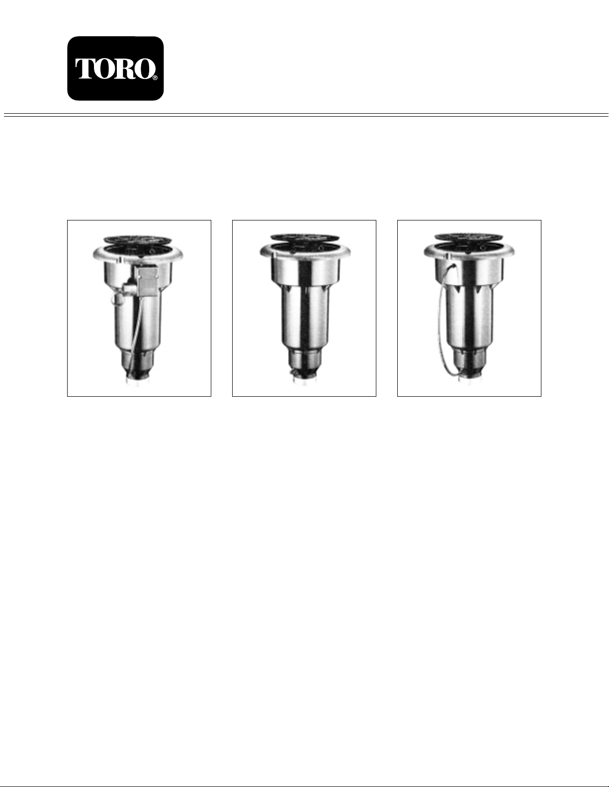
Model 69X-06-XX Model 69X-02-XXModel 69X-01-XX
Specifications
• 78 ft. – 108 ft. Radius
• Pop-Up Nozzle and Cap -
7
⁄8 in.
•1
1
⁄2 in. NPT Female Thread Inlet
• Recommended Operating
Pressure: 60 – 100 PSI
• Maximum Pressure: 150 PSI
• Electric Models:
– Solenoid - 24 VAC
– Inrush Current - .40 Amps
– Holding Current - .235 Amps
• Dimensions:
– Cap Diameter - 7
1
⁄2 in.
– Flange Diameter - 10 in.
– Height - 16 in.
Page 2

2
Performance Chart
Installation Procedure
To assure maximum performance from your 690 Series Rotary
Sprinklers, read these instructions completely prior to installing or
servicing the sprinkler.
Construct Swing Joints
1. Construct triple swing joints for each sprinkler as shown in
Figure 1.Use PVC or ABS pipe nipple for sprinkler connection.
Note: On sites where the possibility of heavy equipment
rolling over a sprinkler exists, the swing joint will flex
preventing damage to the lateral or main lines. On a new
installation in raw ground where the sprinklers are to be
initially installed above the finished grade and lowered when
new turf is established, the swing joint allows sprinkler
repositioning without changing risers. This is a common and
practical procedure which eliminates the problem of dirt
being accidentally introduced into the lateral lines when a
riser is changed.
2. Flush lines thoroughly prior to installing sprinkler.
3. Apply Teflon tape on riser threads. Install sprinkler to riser
and tighten.
CAUTION
Use only Teflon™ tape on riser threads. Use of pipe dope or other types of sealing compounds can
cause deterioration of sprinkler body threads.
Figure 1
Triple Swing Joints
Base Nozzle Set Nozzle Set Nozzle Set
Pressure -90 -91 -92
Size 3/8 in. Size 7/16 in. Size 1/2 in.
PSI Rad. GPM Rad. GPM Rad. GPM
40
50
60 78 ft. 45.1 87 ft. 53.7
70 82 ft. 48.6 91 ft. 57.2 96 ft. 67.5
80 87 ft. 51.0 96 ft. 61.2 100 ft. 74.0
90 89 ft. 54.1 98 ft. 67.3 105 ft. 78.0
100 90 ft. 57.1 100 ft. 73.4 108 ft. 82.2
MODEL NUMBER CODE
69X-XX-XX
Arc Cover Operation Nozzle Set
1 = Quarter Circle 0 = Standard 1 = Valve-in-head -90 = 3/8 in.
2 = Half Circle Hydraulic N.O. -91 = 7/16 in.
Regular Speed 2 = Checkomatic -92 = 1/2 in.
4 = Full Circle 6 = Valve in head
6 = Two Speed electronic
60°-180°
8 = Two Speed
180°
Spacing of Sprinklers
Square Spacing
No Wind 55% of diameter
4 m.p.h. 50% of diameter
8 m.p.h. 45% of diameter
Triangular Spacing
No Wind 60% of diameter
4 m.p.h. 55% of diameter
8 m.p.h. 50% of diameter
Single Row Spacing
No Wind 50% of diameter
4 m.p.h. 50% of diameter
8 m.p.h. 45% of diameter
Conversion Information
• All gallons per minute shown are U.S.
• To convert to Imperial gallons per
minute, multiply by .833.
• To convert to litres per minute, multiply
by 3.78.
• To convert pounds per square inch
(PSI) to atmospheres, divide by 14.7.
• To convert pounds per square inch
(PSI) to kilograms per square
centimeter (kg/cm
2
) divide by 14.22.
• To convert feet to meters, divide by
3.28.
• To convert inches to millimeters, multiply
by 25.4.
A = 150°
B = 165°
C = 195°
D = 210°
Page 3

Connecting Electric Control Wires
1. Route control wires to sprinkler location(s). Provide
enough extra wire at sprinkler to allow for
movement of sprinkler without straining wire
connections. One common wire and one station
wire are required for each sprinkler. See Wire
Sizing Chart, Table 1 for proper application.
2. Attach control wires to solenoid leads using an
approved waterproof splicing method.
CAUTION
All wires must be waterproofed to prevent short
circuit to ground and subsequent controller
damage.
Connecting Hydraulic Control Tubing
1. Route control tubing from controller to sprinkler
location(s).
Note: Leave an 18 inch service loop of tubing at
each sprinkler to facilitate movement of sprinkler and
service operations. Tubing r uns in excess of 1,000
feet are not advisable due to delayed response time.
The controller for hydraulic valve-in-head systems
should never be located more than 25 feet below or
more than 70 feet higher than the valves. Although
there is no limit to the amount of hydraulic valve-inhead sprinklers controlled by one control station,
practical experience suggests the maximum number
of heads normally used is five.
2. Flush tubing thoroughly to remove all air and debris.
3. Remove tube retainer and poly cap from tubing
adapter at base of sprinkler.
4. Slide tube retainer over control tubing and attach tubing to adapter. Slide tube retainer over adapter area to
secure tubing.
System Start-Up
The following is a recommended procedure that will protect system components during system start-up. The
procedure is based on a velocity fill rate of less than 2 feet per second. See Table 2 below.
1. Use jockey pump only to fill system at velocity fill rate of less than 2 feet per second.
2. Use quick coupler keys at all tees and greens with quick coupler valves to bleed air from system lines
during filling process. Do not compress air and then relieve - bleed air while filling system.
3. After water has filled all lines and all air is removed, remove quick coupler keys.
CAUTION
Failure to comply with recommended fill rate will increase line pressure resulting in a water hammer
effect that could damage sprinklers.
Table 2
VOLTAGE WIRE SIZE NUMBER OF VALVES
AT
CONTROLLER CONTROL COMMON 1 2 3 4
110 VAC 14 14 2348 1012 549 353
110 VAC 14 12 2890 1239 673 433
110 VAC 14 10 3378 1448 786 505
110 VAC 12 12 3759 1604 873 561
110 VAC 12 10 4591 1973 1071 688
110 VAC 12 8 5411 2328 1263 812
110 VAC 10 10 5945 2555 1387 892
115 VAC 14 14 2765 1309 846 549
115 VAC 14 12 3393 1608 1039 673
115 VAC 14 10 3962 1877 1213 783
115 VAC 12 12 4394 2082 1346 872
115 VAC 12 10 5397 2557 1652 1071
115 VAC 12 8 6364 3018 1949 1263
115 VAC 10 10 6986 3311 2140 1387
Table 1 - Wire Sizing Chart
Maximum Allowable Length in Feet From Controller to VIH Sprinklers.
Chart based on the following: Transformer - 115 VAC - 124 VAC, 45 VA
Coil Assy. - 24 VAC, 60 Hz
Holding - .21 Amps
In Rush - .42 Amps
3
WARNING
TO PREVENT PERSONAL INJURY, DO NOT STAND DIRECTLY OVER ANY
COMMERCIAL OR LARGE TURF HEAD DURING FILL OR WHEN ACTIVATING
MANUALLY AT THE HEAD.
Pipe Size Gallons Per Velocity - Feet Pipe Size Gallons Per Velocity - Feet
Inches Minute Per Second Inches Minute Per Second
1/2 2 1.60 3 45 1.86
3/4 3 1.92 4 75 1.87
1 5 1.50 6 150 1.73
1-1/4 10 1.86 8 250 1.70
1-1/2 10 1.41 10 450 1.97
2 20 1.80 12 500 1.55
2-1/2 30 1.84
Page 4
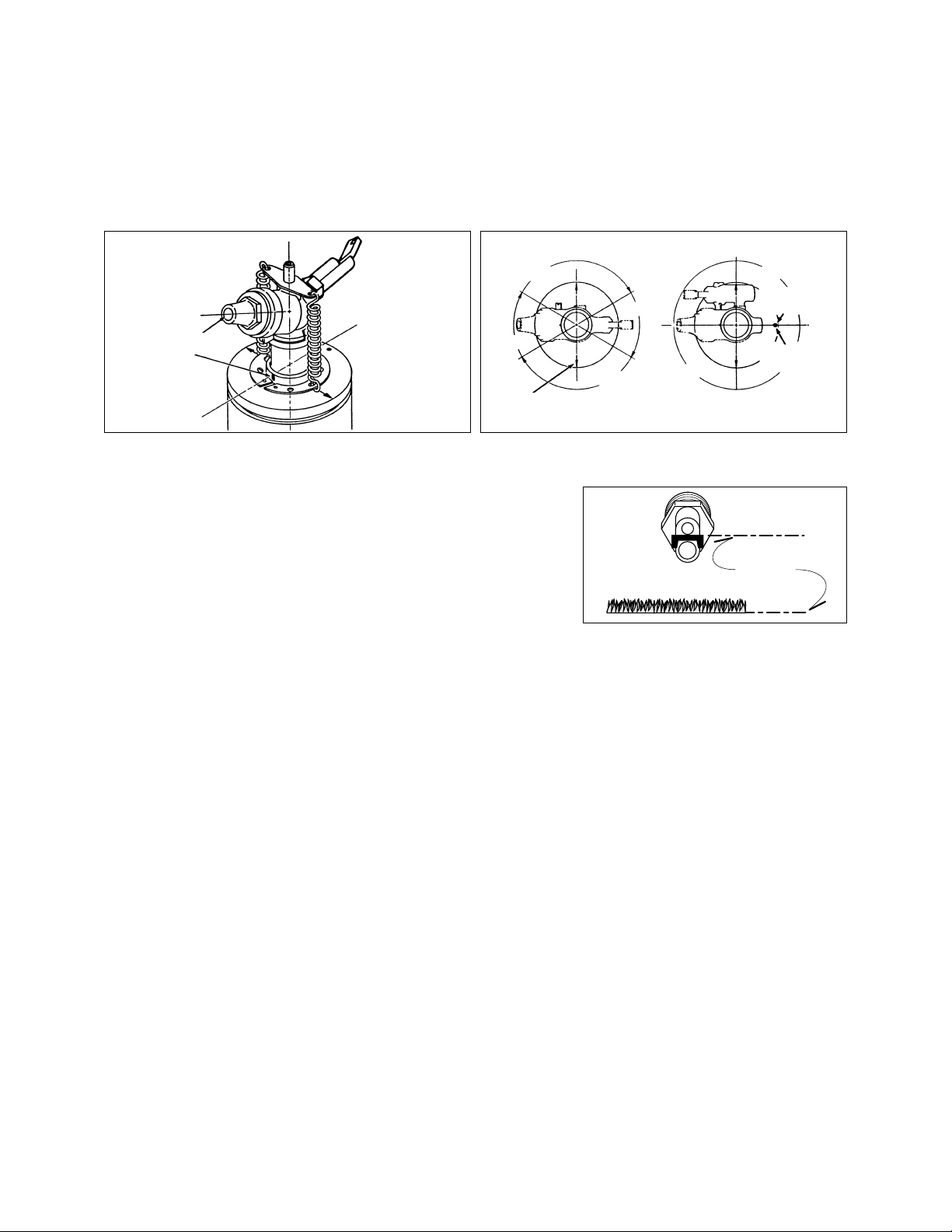
Two-Speed Sprinkler Alignment - Models 696 and 698
There are two types of full circle sprinklers which have special arcs of slower then regular speed. Alignment of
the heads is critical for proper performance. The model 696 sprinkler is a two-speed head with two 60° and two
120° arcs of speed. A red button on the drive assembly indicates it is a two-speed 60°–120° head and acts as a
pointer toward the center of the fairway or the next head in the row of sprinklers. The model 698 sprinkler is a
two-speed head with two 180° arcs of speed. A yellow button on the drive assembly indicates it is a two-speed
180° head and also indicates the center of the regular speed side. Align the sprinkler so the button points toward
the center of the overlapped area of coverage. When a nozzle assembly is changed on either the 696 or 698
head, the main nozzle must be aligned with the small boss on the bull gear of the drive assembly.
Back Nozzle Alignment
When replacing the back nozzle, align it so the nozzles are vertical and
the ramp is parallel to the ground. Use a 5/8 in. wrench to remove and
align the back nozzle. See example at right.
Pilot Valve Operation
The main function of the pilot valve is to control the operation of the main valve located in the base of the
sprinkler body. The main valve is operated by the release of water metered through the pilot valve when it is
activated either manually or automatically by the 24 VAC coil assembly.
Another important function of the pilot valve is to regulate the water pressure to the sprinkler nozzle. Pressure
regulation compensates for large variations within the system and maintains a constant pressure for optimum
sprinkler operation. The 690 series pilot valve is factory set to regulate at 80 or 100 PSI depending on sprinkler
model.
Sprinkler operation mode is set using a Toro Selector Tool (P/N 995-15) inserted through the body flange onto the
pilot valve D shaped selector-cam. The "AUTO" mode permits automatic operation from the system controller. The
"ON" mode opens the main valve for manual operation and "OFF" mode prevents the main valve from opening.
System Troubleshooting
Pilot Valve
Possible equipment failures with causes and corrective action are listed below.
PROBLEM POSSIBLE CAUSE – CORRECTIVE ACTION
1. Sprinkler will not turn on (a) No 24 VAC to coil assembly - Measure voltage with DVM.
Check wiring and controller program - Refer to Controller Operating
Instructions.
(b) Selector cam in "OFF" position - Set to "AUTO" position.
(c) Debris in pilot valve assembly - Disassemble and remove all debris (See
Servicing Pilot Valve page 8.)
2. Sprinkler will not shut off (a) Constant 24 VAC from controller - Check for voltage using a DVM. If
voltage is present, disconnect wire.
If sprinkler closes, service controller. Refer to Controller Service Manual.
(b) Selector cam in manual "ON" position - Set to "AUTO" or "OFF" position.
(c) Debris in pilot valve assembly - Disassemble and remove all debris (See
Servicing Pilot Valve page 8.)
4
Figure 2 - Nozzle Alignment
Figure 3 - Alignment of Drive Assembly to Turf
Coverage Area
Align main nozzle directly over
raised timing mark on bull gear.
120˚
Regular Speed
60˚
Half Speed
120˚
Regular Speed
60˚
Half Speed
180˚
Half Speed
180˚
Half Speed
Align yellow dot facing
opposing sprinkler row.
(Two row design)
Align yellow dot with
center of green.
(Green application)
RAMP ALIGNMENTL
PARALLEL
GROUND LINEL
Page 5

5
System Troubleshooting (continued)
Sprinklers
Possible equipment failures with causes and corrective action are listed below.
PROBLEM POSSIBLE CAUSE – CORRECTIVE ACTION
1. Sprinkler won't rotate (a) Stator too large for nozzle - Use proper nozzle.
(b) Debris wedged between stator and turbine - Remove obstruction.
(c) Drive assembly defective - Replace with new drive assembly.
2. Head sticks up (a) Dirt in riser assembly - Flush out. (See Flushing Procedure.)
(b) Damaged riser - Replace.
3. Poor distribution pattern (a) Nozzle plugged with debris - Clean or replace nozzle.
(b) Nozzle orifice/stream straightener damaged - Replace nozzle.
(c) Low operating pressure - Determine why system overloaded and correct.
(d) Head misaligned during installation (two-speed only) - Realign properly.
4. Valve won't close (a) Leak in control tubing - Isolate and repair.
(Hydraulic 69X-01-XX) (b) Pilot valve leak in controller - Confirm by observing constant dripping
from discharge line of controller. Refer to Controller Service Manual.
(c) Foreign object keeping valve from seating - Remove, clean and check
valve for damage. Replace if necessary.
(d) Damaged piston seal or piston assembly - Replace valve assembly.
(e) Valve not properly communicated to tube in body - Reassemble if
necessary.
5. Valve won't open (a) Plugged controller discharge line or discharge port in pilot valve -
(Hydraulic 69X-01-XX) Verify by checking for discharge at discharge line when station is
activated - If no discharge, refer to Controller Service Manual.
(b) Water supply to sprinkler closed off - Determine if closure is shut-off
valve or blockage and correct.
6. Valve won't close (a) Leak in pilot valve assembly - Replace pilot valve assembly.
(Electric 69X-06-XX) (b) Plugged supply screen on piston - Clean or replace screen.
(c) Manual control selector on pilot valve assembly turned to "ON" position -
Turn to "AUTO" position.
7. Valve won't open (a) Control (field) wires severed - Isolate and repair.
(Electric 69X-06-XX) (b) Defective solenoid - Replace solenoid.
(c) No power to controller - Establish controller power.
(d) No power from controller to solenoid - Check for blown fuse and replace.
(e) Manual control selector on pilot valve assembly turned to "OFF" position
- Turn to "AUTO" position.
(f) No supply from main valve and piston - Remove supply tube from supply
port. If no supply port, repair valve and piston assembly.
8. Valve leaks (a) Damaged or blocked valve seat - Remove blockage and, if necessary,
replace valve assembly.
(b) Damaged piston seal or piston assembly - Replace valve assembly.
(c) Low pressure on supply line on hydraulic NO sprinklers - Check for low
pressure reason and correct.
9. Several valves on different (a) Control tubing leak which lowers supply pressure to other stations -
stations fail to close Turn controller from station to station until a station is reached where
(Hydraulic 69X-01-XX) only valves on that station stay open. The leak would be in the tubing on
that station - Isolate and repair.
(b) Leak in supply line to controller - Verify by checking pressure in all
control lines.
(c) Leak in controller pilot valve - Verify by constant discharge on controller -
Refer to Controller Service Manual.
(d) Plugged supply line filter - Replace filter if more than 3 psi differentialexists.
Page 6

Servicing Procedures
Introduction
The 690 Series rotary sprinkler is designed to provide the user trouble free operation for many years without
scheduled maintenance. Should it become necessary to disassemble the sprinkler to correct a malfunction or
replace a component, all internal parts of the sprinkler are accessible from the top. Refer to the Troubleshooting
Procedure in this manual in the event of a malfunction. Some special tools are required for disassembly and/or
maintenance of the sprinkler and are available from your Toro dealer.
Servicing Sprinkler Mechanism and V alve Assembly
(Refer to Figure 8 for the following procedure.)
1. Remove rubber cap plug (1) if installed.
2. Remove machine screw (2) and cap (4).
3. Using snap ring pliers (P/N 995-07), remove head snap ring (11).
4. Grasping nozzle base (9), pull sprinkler mechanism out of body.
Note: Due to O-ring seal compression between drive assemb ly and body, considerable resistance may be f elt
when removing sprinkler mechanism.
5. Unhook and remove retraction springs (6) from spring strap (5) and spring collar (14).
6. To remove nozzle base assembly, hold riser and riser pliers (P/N 995-17) and turn nozzle base assembly
counterclockwise.
7. Using appropriate size end wrenches, turn nozzles counterclockwise to remove from nozzle base.
8. Carefully pull stream straightener (8) out of nozzle base using needle nose pliers.
9. To remove stator (15), insert screwdriver blade between stator and drive assembly housing (13) and pry apart.
Note: A small notch for screwdriver blade insertion is provided on edge of stator.
10. Thoroughly clean and inspect all parts. Replace parts as required.
Note: If changing nozzle to a different size, appropriate stator must also be installed to ensure proper rotation
speed and coverage.
1 1. To remove valve assembly, squeeze ears of snap ring together with snap ring pliers (P/N 995-07) and remove
snap ring from sprinkler body . (See Figure 4).
CAUTION
If snap ring is difficult to remove, there may be residual water pressure in the system. Recheck the water
supply to insure it is turned off and all pressure has been totally eliminated before removing the snap
ring and valve.
12. Use valve removal tool (P/N 995-08) to remove valve assembly from base of sprinkler body. Valve Removal Tool
is inserted into sprinkler body and pushed through valve ribs to the underside of valve. A slight twist will lock
tool to valve enabling removal by pulling straight up and out. (See Figure 5.)
NOTE: If valve removal tool is not available, use snap ring pliers to grasp rib of valve assembly and pull up and
out of sprinkler body .
6
WARNING
TO PREVENT POSSIBLE INJURY DURING SPRINKLER SERVICING PROCEDURES,
CONFIRM THE FOLLOWING CONDITIONS EXIST PRIOR TO STARTING.
A. WATER SUPPLY TO SPRINKLER IS SHUT OFF AT SOURCE.
B. SYSTEM PRESSURE IS BLED FROM SYSTEM, INCLUDING CONTROL TUBES.
C. A.C. POWER IS DISCONNECTED AT SOURCE
WARNING
POSITIVELY SHUT OFF WATER SUPPLY AT SOURCE PRIOR TO REMOVING VALVE
ASSEMBLY. BLEED ALL PRESSURE FROM SYSTEM INCLUDING CONTROL TUBES.
FAILURE TO DEPRESSURIZE SYSTEM PRIOR TO SNAP RING REMOVAL COULD
CAUSE VALVE MECHANISM TO EJECT FROM SPRINKLER BODY UNDER
PRESSURE RESULTING IN POSSIBLE SERIOUS INJURY TO PERSONNEL.
Page 7

13. To reinstall valve assembly with snap ring
and to prevent damage to the
communication tube in sprinkler body, use
valve insertion tool (P/N 995-11). Valve
insertion tool will automatically line up valve
assembly with sprinkler body communication
tube and correctly seat the snap ring. (See
Figure 6).
NOTE: It is possible to install the snap ring
backwards (upside down). See inset in
Figure 6 to insure that snap ring is installed
in the correct manner.
Figure 6
Using Valve Insertion Tool to Install Valve Assembly
with Snap Ring Pliers
7
Figure 4
Using Snap Ring Pliers to Remove Snap Ring
Figure 5
Using Valve Removal Tool to Remove Valve Assembly
Page 8

8
Servicing Pilot Valve Assembly
Note: Assure water supply to sprinkler is positively shut off and all residual pressure has been bled. If sprinkler
is pressurized, main valve will open when the pilot valve control tube is disconnected.
Refer to Figure 7 for the following procedure.
1. Carefully remove turf and soil from side of sprinkler to expose pilot valve and control tubing.
2. Remove two retaining screws from pilot valve housing.
3. Pull pilot valve assembly away from sprinkler body and cut control tubing just below tube retainer.
Unless
pilot valve has been previously removed, control tubing length will be sufficient for re-connection.
4. Remove tube retainer and remaining piece of control tubing from valve body fitting.
5. Remove solenoid (1) or NC adapter (2) by turning it counterclockwise.
6. Pull pilot valve body assembly (4–12) out of housing.
7. Remove diaphragm assembly (12), piston (11) and spring (10).
8. Remove selector (7) and plunger assembly (5 or 6).
Selector retains plunger in body.
9. Thoroughly clean and inspect all parts. Replace damaged parts as necessary and reassemble in reverse order.
Page 9

9
Figure 7 Pilot Valve, Current
Item No. Part No. Nomenclature Quantity
Per Assy.
1 89-1905 Solenoid, Pilot Valve & Valve 1
2 89-6005 Adapter, Pilot Valve, NC 1
3 89-0001 Housing, Pilot Valve 1
4 360-0220 O-Ring, .070" x .551" x .691" 1
5 35-9993 Plunger Assy., Elec. 1
6 89-6003 Plunger Assy., NC 1
7 - - - - - Selector (See Service Parts and Assemblies below) 1
8 1-2035 O-Ring, .070" x .114" x .254" 1
9 89-6004 Body Assy., Pilot Valve 1
10 35-9970 Spring, 50 lbs., Black 1
10 35-9971 Spring, 65 lbs., Green 1
10 35-9972 Spring, 80 lbs., Red 1
10 35-9973 Spring, 100 lbs., Blue 1
11 89-0029 Piston 1
12 89-0005 Diaphragm Assembly 1
SERVICE PARTS AND ASSEMBLIES
89-0009 Pilot Valve Assy., 50 lbs., Elec.
89-0010 Pilot Valve Assy., 65 lbs., Elec.
89-0011 Pilot Valve Assy., 80 lbs., Elec.
89-0012 Pilot Valve Assy., 100 lbs., Elec.
89-3918 Pilot Valve Assy., 50 lbs., NC
89-3919 Pilot Valve Assy., 65 lbs., NC
89-7125 Pilot Valve Assy., 80 lbs., NC
89-7126 Pilot Valve Assy., 100 lbs., NC
89-0998 Pilot Valve less Solenoid, 50 lbs., Elec.
89-0999 Pilot Valve less Solenoid, 65 lbs., Elec.
89-1000 Pilot Valve less Solenoid, 80 lbs., Elec.
89-1001 Pilot Valve less Solenoid, 100 lbs., Elec.
102-0343 Selector Cam Assy. (Includes Items 7-8)
1
4
9
12
10
8
11
3
5
6
2
7
Page 10

10
Figure 8 690 Series
69X-XX-XXX
Arc Body Nozzle Pressure Regulation *
1 = 90° Quarter Circle 01 = NPT, NO Valve-In-Head 90 8 = 80 PSI
2 = 180° Half Circle 02 = NPT, Check-O-Matic 91 1 = 100 PSI
4 = Full Circle 06 = NPT, Electric Valve-In-Head 92
6 = Full Circle, 2-Speed, 08 = NPT, NC Valve-In-Head
(60°–120°)
8 = Full Circle, 2-Speed,
* Pressure Regulation available on
(180°–180°) Electric & NC VIH models only.
**
A = 150° ** Special arcs not available on
**
B = 165° Normally Closed (NC) models.
**
C = 195° § Pre-1998 models only.
**
D = 210°
Model Number Information
§
Page 11

11
Item No. Part No. Nomenclature Quantity
Per Assy.
1 3-2518 Plug, Cap , Rubber 1
2 3-3567 Screw, Machine, 1/4 - 20 x3/8" 1
3 3-3529 Cap Assy., Rubber Cover (Includes Item 4) 1
- 3-3582 Cover, Cap, Rubber 1
4 3-3532 Cap, Blank 1
5 9-2734 Strap, Spring 1
6 9-2738 Spring, Retraction 2
7 89-5816 Nozzle, Main, 3/8", #90 1
7 3-3542 Nozzle, Main, 7/16", #91 1
7 3-3543 Nozzle, Main, 1/2", #92 1
8 3-3535 Straightener, Stream 1
9 3-3531 Base, Nozzle, Full Circle 1
9 9-1079 Base, Nozzle, Part Circle 1
10 9-5535 Nozzle, Back 1
11 3-3536 Ring, Snap, Head 1
12 363-3210 O-Ring, .139" x 4.359" x 4.637" 1
13 9-1849 Drive Assy., Quarter Circle, 691 (Includes Item 14) 1
13 9-1850 Drive Assy., Half Circle, 692 (Includes Item 14) 1
13 3-3585 Drive Assy., Full Circle, 694 (Includes Item 14) 1
13 35-5123 Drive Assy., Full Circle, 696, 2-Speed, 60°-120° (Includes Item 14) 1
13 89-8145 Drive Assy., 150° (Includes Item 14) 1
13 89-8146 Drive Assy., 165° (Includes Item 14) 1
13 89-8147 Drive Assy., 195° (Includes Item 14) 1
13 89-8148 Drive Assy., 210° (Includes Item 14) 1
14 9-2736 Collar, Spring 1
15 3-3586 Stator, 3/8", #90 1
15 3-3568 Stator, 7/16", #91 1
15 3-3555 Stator, 1/2", #92 1
16 3-3304 Ring, Snap, Valve 1
17 9-1479 Cylinder Assy., Hyd., NO, COM & Drain Valve 1
17 9-1486 Cylinder Assy., El & Hyd., NC 1
18 3-3311 Spring, Valve, COM 1
18 3-3323 Spring, Valve, EL, Hyd., NO, Hyd., NC & Drain Valve 1
19 89-1201 Piston Assy., Valve, Hyd., NO &COM 1
19 3-3355 Piston Assy., Valve, Drain 1
19 89-0937 Piston Assy., Valve, El, Hyd., NC 1
20 - - - - - - Body, 690 (See Service Items) 1
21 9-6002 Adapter, Tubing, Threaded, 1/4" 1
22 * 89-8157 Cap, Poly, 1/4" 1
23 * 900-40 Retainer, Tube 2
24 9-2624 Tubing, Poly 16.5" 1
25 See page 9 Pilot Valve Assy. 1
26 3-2696 Screw, Tap, #8 2
27 3-3581 Cover, Body, Rubber 1
SERVICE PARTS AND ASSEMBLIES
2-9647 Screw, Machine, 10-24 x 1-1/2" 1
3-2606 Adapter, Poly, 1/4", COM 1
3-3579 Body, Electric wo/VIH (Includes Items 20-23) 1
89-4861 Body, Electric w/VIH (Includes Items 16-23) 1
89-4873 Body, Electric w/VIH, 80 lb. PV (Includes Items 16-21 and 23-26) 1
89-1019 Body, Electric w/VIH, 100 lb. PV (Includes Items 16-21 and 23-26) 1
3-3558 Body, Hydraulic NO wo/VIH (Includes Items 20-23) 1
89-1038 Body, Hydraulic NO w/VIH (Includes Items 16-23) 1
9-1497 Body, COM wo/VIH (Includes Items 20, 21, 23 and 24) 1
89-4879 Body, COM w/VIH (Includes Items 16-21, 23 and 24) 1
89-0088 Pilot Valve Assy, 100 Lbs. w/Tubing 1
9-4079 Nozzle Assy., 690-90 (Includes Items 7-10) 1
9-4080 Nozzle Assy., 690-91 (Includes Items 7-10) 1
9-4081 Nozzle Assy., 690-92 (Includes Items 7-10) 1
9-4083 Nozzle Assy., 694-90 (Includes Items 7-10) 1
9-4084 Nozzle Assy., 694-91 (Includes Items 7-10) 1
9-4085 Nozzle Assy., 694-92 (Includes Items 7-10) 1
9-5747 Nozzle Base Assy., 690 1
9-2669 Retraction Assy., Spring (Includes Items 5, 6,11 & 14) 1
690-01 Kit, Cover, Rubber (Includes Items 1, 3 & 27) 1
9-7271 Adapter, Tubing, Oversized 1
* Order through Finished Goods Distribution System – Minneapolis
Page 12

© 2001 The Toro Company, Irrigation Division • An ISO 9001-Certified Facility Form No. 366-0041 Rev. B
 Loading...