

Page 1
FormNo.3421-177RevB
MBTX2500TrackedMudBuggy
ModelNo.68138—SerialNo.402100000andUp
ModelNo.68138G—SerialNo.402100000andUp
ModelNo.68138HD—SerialNo.400000000andUp
Registeratwww.T oro.com.
OriginalInstructions(EN)
*3421-177*B
Page 2
ItisaviolationofCaliforniaPublicResourceCode
Section4442or4443touseoroperatetheengineon
anyforest-covered,brush-covered,orgrass-covered
landunlesstheengineisequippedwithaspark
arrester,asdenedinSection4442,maintainedin
effectiveworkingorderortheengineisconstructed,
equipped,andmaintainedforthepreventionofre.
Becauseinsomeareastherearelocal,state,or
federalregulationsrequiringthatasparkarresterbe
usedontheengineofthismachine,asparkarresteris
availableasanoption.Ifyourequireasparkarrester,
contactyourAuthorizedServiceDealer.GenuineToro
sparkarrestersareapprovedbytheUSDAForestry
Service.
Theenclosedengineowner'smanualissupplied
forinformationregardingtheUSEnvironmental
ProtectionAgency(EPA)andtheCaliforniaEmission
ControlRegulationofemissionsystems,maintenance,
andwarranty.Replacementsmaybeorderedthrough
theenginemanufacturer.
WARNING
CALIFORNIA
Proposition65Warning
Theengineexhaustfromthisproduct
containschemicalsknowntotheStateof
Californiatocausecancer,birthdefects,
orotherreproductiveharm.
Batteryposts,terminals,andrelated
accessoriescontainleadandlead
compounds,chemicalsknownto
theStateofCaliforniatocause
cancerandreproductiveharm.Wash
handsafterhandling.
Useofthisproductmaycauseexposure
tochemicalsknowntotheStateof
Californiatocausecancer,birthdefects,
orotherreproductiveharm.
Introduction
Thismachineisintendedtobeusedbyprofessional,
hiredoperatorsincommercialapplications.This
machineisastable,reliable,andproductivemachine
forcarryingandmovingmaterialsforanyjobsite.Itis
primarilydesignedtomoveconcrete,mortar,gravel,
dirt,ordebrisaroundjobsites.
Readthisinformationcarefullytolearnhowtooperate
andmaintainyourproductproperlyandtoavoid
injuryandproductdamage.Youareresponsiblefor
operatingtheproductproperlyandsafely .
YoumaycontactT orodirectlyatwww.T oro.com
forproductsafetyandoperationtrainingmaterials,
accessoryinformation,helpndingadealer,orto
registeryourproduct.
Wheneveryouneedservice,genuineToroparts,or
additionalinformation,contactanAuthorizedService
DealerorToroCustomerServiceandhavethemodel
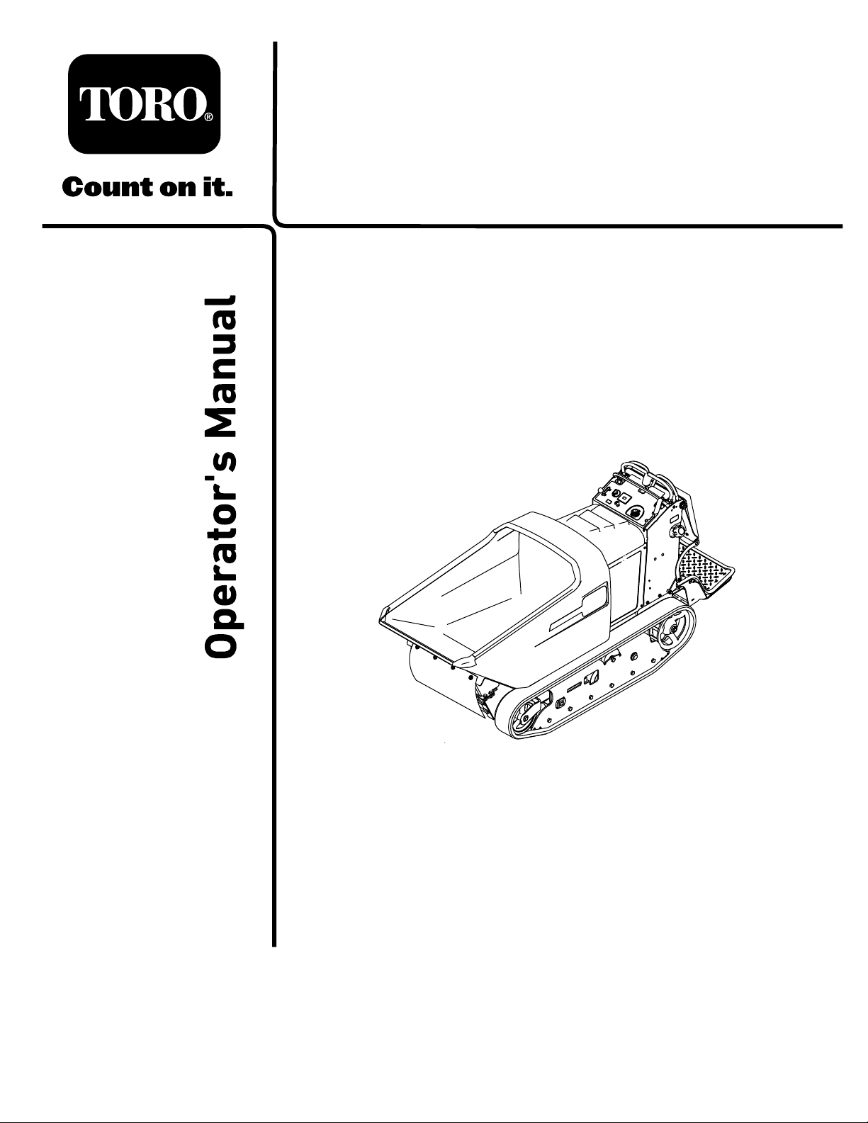
andserialnumbersofyourproductready.Figure1
identiesthelocationofthemodelandserialnumbers
ontheproduct.Writethenumbersinthespace
provided.
Important:Withyourmobiledevice,youcan
scantheQRcodeontheserialnumberdecal(if
equipped)toaccesswarranty,parts,andother
productinformation.
©2018—TheToro®Company
8111LyndaleAvenueSouth
Bloomington,MN55420
Figure1
1.Modelandserialnumberlocation
ModelNo.
SerialNo.
Thismanualidentiespotentialhazardsandhas
safetymessagesidentiedbythesafety-alertsymbol
(Figure2),whichsignalsahazardthatmaycause
Contactusatwww.Toro.com.
2
g241847
PrintedintheUSA
AllRightsReserved
Page 3

seriousinjuryordeathifyoudonotfollowthe
recommendedprecautions.
Figure2
1.Safety-alertsymbol
Thismanualuses2wordstohighlightinformation.
Importantcallsattentiontospecialmechanical
informationandNoteemphasizesgeneralinformation
worthyofspecialattention.
Contents
Safety.......................................................................4
SafeOperatingPractices....................................4
g000502
SafetyandInstructionalDecals..........................6
ProductOverview.....................................................9
Controls.............................................................9
Specications..................................................10
Attachments/Accessories.................................10
Operation................................................................10
AddingFuel......................................................10
PerformingDailyMaintenance..........................12
OperatingtheParkingBrake.............................12
OperatingtheThrottle.......................................13
OperatingtheChoke.........................................13
StartingtheEngine...........................................13
ShuttingOfftheEngine.....................................14
OperatingtheHopper.......................................14
RemovingDebrisfromtheMachine..................14
LoweringtheHopperwithoutPower..................15
TransportingtheMachine.................................15
LiftingtheMachine...........................................16
Maintenance...........................................................17
RecommendedMaintenanceSchedule(s)...........17
Pre-MaintenanceProcedures..............................18
ReleasingtheCushionforRearAccess............18
UsingtheCylinderLock....................................18
Lubrication..........................................................19
GreasingtheMachine.......................................19
EngineMaintenance...........................................19
ServicingtheAirCleaner..................................19
CheckingtheEngine-OilLevel..........................20
ChangingtheEngineOilandFilter....................21
ServicingtheSparkPlugs.................................22
CleaningtheBlowerHousing............................23
FuelSystemMaintenance...................................24
ReplacingtheFuelFilter...................................24
DrainingtheFuelT ank......................................24
RemovingtheFuelT ank...................................25
ElectricalSystemMaintenance...........................25
ServicingtheBattery.........................................25
ServicingtheFuses..........................................27
DriveSystemMaintenance..................................27
ServicingtheTracks.........................................27
ServicingtheDriveBelt.....................................29
ControlsSystemMaintenance.............................30
AdjustingtheMotion-ControlLevers.................30
BrakeMaintenance...........................................31
HydraulicSystemMaintenance...........................32
ServicingtheHydraulicDriveSystem...............32
ServicingtheHydraulicLiftSystem...................34
CheckingtheHydraulicLines...........................36
Cleaning..............................................................37
RemovingDebrisfromtheMachine..................37
Storage...................................................................38
3
Page 4

Safety
Improperuseormaintenanceofthemachinecan
resultininjury .Toreducethepotentialforinjury,
complywiththesesafetyinstructionsandalwayspay
attentiontothesafety-alertsymbol(Figure2),which
meansCaution,Warning,orDanger—personal
safetyinstruction.Failuretocomplywiththe
instructionmayresultinpersonalinjuryordeath.
SafeOperatingPractices
–Donotstorethemachineorfuelcontainer
wherethereisanopename,spark,orpilot
light,suchasonawaterheaterorother
appliance.
–Ifyouspillfuel,donotattempttostartthe
engine;avoidcreatinganysourceofignition
untilthefuelvaporshavedissipated.
•Checkthattheoperator'spresencecontrols,safety
switches,andshieldsareattachedandfunctioning
properly.Donotoperatethemachineunlessthey
arefunctioningproperly.
WARNING
Engineexhaustcontainscarbonmonoxide,
anodorlessgasthatislethalifinhaled.
Donotruntheengineindoorsorinan
enclosedarea.
Training
•ReadtheOperator'sManualandothertraining
material.Iftheoperator(s)ormechanic(s)cannot
readthismanual,itistheowner'sresponsibilityto
explainthismaterialtothem.
•Becomefamiliarwiththesafeoperationofthe
equipment,operatorcontrols,andsafetysigns.
•Alloperatorsandmechanicsshouldbetrained.
Theownerisresponsiblefortrainingtheusers.
•Neverletchildrenoruntrainedpeopleoperateor
servicetheequipment.Localregulationsmay
restricttheageoftheoperator.
•Theowner/usercanpreventandisresponsible
foraccidentsorinjuriesoccurringtohimselfor
herself,otherpeopleorproperty .
Preparation
•Wearappropriateclothingincludinghardhat,eye
protection,longpants,substantial,slip-resistant
footwear,andhearingprotection.Tiebacklong
hair.Donotwearloosejewelry.
•Inspecttheareawheretheequipmentistobe
usedandensurethatallobjectsareremovedfrom
themachinebeforeuse.
•Knowandmarkthelocationsofallutilitylines.
•Useextracarewhenhandlingfuels.Theyare
ammableandvaporsareexplosive.
–Extinguishallcigarettes,cigars,pipes,and
othersourcesofignition.
–Useonlyanapprovedcontainer
–Donotremovethefuelcaporllthefueltank
whiletheengineisrunningorhot.
–Donotaddordrainfuelinanenclosedspace.
Operation
•Useyourfullattentionwhileoperatingthe
machine.Donotengageinanyactivitythat
causesdistractions;otherwise,injuryorproperty
damagemayoccur.
•Neverrunanengineinanenclosedorpoorly
ventilatedarea.
•Operatethemachineonlyingoodlight,keeping
awayfromholesandhiddenhazards.
•Ensurethatalldrivesareinneutralbefore
startingtheengine.Starttheengineonlyfromthe
operator'sposition.
•Donotoperatethemachinewiththeguards
notsecurelyinplace.Besureallinterlocksare
attached,adjustedproperly,andfunctioning
properly.
•Donotchangetheenginegovernorsettingor
overspeedtheengine.
•Stopthemachineonlevelground,lowerthe
hopper,shutofftheengine,andremovethekey
beforeleavingtheoperator'spositionforany
reason.
•Nevercarrypassengersandkeeppetsand
bystandersaway.
•Slowdownandusecautionwhenmakingturns
andcrossingroadsandsidewalks.
•Donotoperatethemachinewhileill,tired,or
undertheinuenceofalcoholordrugs.
•Usecarewhenloadingorunloadingthemachine
intoatrailerortruck.
•Usecarewhenapproachingblindcorners,shrubs,
trees,orotherobjectsthatmayobscurevision.
•Ensurethattheareaisclearofotherpeoplebefore
operatingthemachine.Shutoffthemachineif
anyoneentersthearea.
•Neverleavearunningmachineunattended.
•Donotexceedtheratedoperatingcapacity,asthe
machinemaybecomeunstablewhichmayresult
inlossofcontrol.
•Neverjerkthecontrols;useasteadymotion.
4
Page 5

•Watchfortrafcwhenoperatingnearorcrossing
roadways.
•Donottouchpartsthatmaybehotfromoperation.
Allowthemtocoolbeforeattemptingtomaintain,
adjust,orservice.
•Checkforoverheadclearances(i.e.,branches,
doorways,electricalwires)beforedrivingunder
anyobjectsanddonotcontactthem.
•Ensurethatyouoperatethemachineinareas
wheretherearenoobstaclesclosetoyou.Failure
tomaintainadequatedistancefromtrees,walls,
andotherbarriersmayresultininjuryasthe
machinebacksupduringoperationifyouare
notattentivetothesurroundings.Operatethe
machineonlyinareaswherethereissufcient
clearancefortheoperatortosafelymaneuverthe
product.
•Locatethepinchpointareasmarkedonthe
machineandkeephandsandfeetawayfrom
theseareas.
•Operatethemachineonlyingoodvisibilityand
appropriateweatherconditions.Donotoperate
themachinewhenthereistheriskoflighting.
•Donotoverloadthehopperandalwayskeepthe
loadlevelwhenoperatingthemachine.
SlopeOperation
•Slopesareamajorfactorrelatedtoloss-of-control
andtip-overaccidents,whichcanresultinsevere
injuryordeath.Theoperatorisresponsiblefor
safeslopeoperation.operatingthemachineon
anysloperequiresextracaution.Beforeusingthe
machineonaslope,youmust:
–Reviewandunderstandtheslopeinstructions
inthemanualandonthemachine.
–Evaluatethesiteconditionsofthedayto
determineiftheslopeissafeformachine
operation.Alwaysusecommonsense
andgoodjudgmentwhenperformingthis
evaluation.Changesintheterrain,suchas
moisture,canquicklyaffecttheoperationof
themachineonaslope.
•Raisingthehopperonaslopeaffectsthestability
ofthemachine.Keepthehopperinthelowered
positionwhenonslopes.
•Whenoperatingonaslope,foldtheplatformup
andwalkbehindthemachineuntilitisonat
ground.
•Operateupanddownslopeswiththeheavy
endofthemachineuphill.Weightdistribution
changeswithafullhopper.Afullhoppermakes
thefrontofthemachinetheheavyend,sowhen
travelingupordownslopeswithafullhopper,
walk-behindthemachinewiththefullhopperuphill.
•Identifyhazardsatthebaseoftheslope.Do
notoperatethemachineneardrop-offs,ditches,
embankments,waterorotherhazards.The
machinecouldsuddenlyrolloverifawheelortrack
goesovertheedgeortheedgecollapses.Keep
asafedistance(twicethewidthofthemachine)
betweenthemachineandanyhazard.
•Avoidstarting,stopping,orturningthemachineon
aslope.Avoidmakingsuddenchangesinspeed
ordirection;turnslowlyandgradually.
•Keepallmovementsonslopesslowandgradual.
Donotmakesuddenchangesinspeedor
direction.
•Donotoperatethemachineunderanyconditions
wheretraction,steering,orstabilityisinquestion.
Beawarethatoperatingthemachineonwetgrass,
acrossslopesordownhillmaycausethemachine
tolosetraction.Lossoftractiontothewheelsor
tracksmayresultinslidingandalossofbraking
andsteering.Themachinecanslideevenifthe
wheelsortracksarestopped.
•Removeormarkobstaclessuchasditches,holes,
ruts,bumps,rocksorotherhiddenhazards.T all
grasscanhideobstacles.Uneventerraincould
overturnthemachine.
•Ifyoulosecontrolofthemachine,stepoffand
awayfromthedirectionoftravelofthemachine.
MaintenanceandStorage
•Lettheenginecoolbeforestoringanddonotstore
themachinenearanopename.
•Engagetheparkingbrake,shutofftheengine,
removethekey ,andwaitforallmovementto
stopbeforeadjusting,cleaning,orrepairingthe
machine.
•Cleandebrisfromdrives,mufers,andtheengine
tohelppreventres.Cleanupoilorfuelspills.
•Donotstorefuelnearamesordrainindoors.
•Parkthemachineonlevelground.Neverallow
untrainedpersonneltoservicethemachine.
•Usejackstandstosupportcomponentswhen
required.
•Carefullyreleasepressurefromcomponentswith
storedenergy.
•Disconnectthebattery,negativeterminalrstand
positiveterminallast,beforemakinganyrepairs.
Connectthebatterypositiveterminalrstand
negativeterminallast.
•Keepyourhandsandfeetawayfrommoving
parts.Ifpossible,donotmakeadjustmentswith
theenginerunning.
5
Page 6
•Chargebatteriesinanopen,well-ventilatedarea,
awayfromsparkandames.Unplugthecharger
beforeconnectingordisconnectingitfromthe
battery.Wearprotectiveclothinganduseinsulated
tools.
•Keepallpartsingoodworkingconditionandall
hardwaretightened.Replaceallwornordamaged
decals.
•Usethecylinderlocktosecurethehopperinthe
raisedposition.
•Keepnutsandboltstight.Keepequipmentin
goodcondition.
•Nevertamperwithsafetydevices.
•UseonlygenuineT ororeplacementpartsto
ensurethatoriginalstandardsaremaintained.
SafetyandInstructionalDecals
Safetydecalsandinstructionsareeasilyvisibletotheoperatorandarelocatednearanyarea
ofpotentialdanger.Replaceanydecalthatisdamagedormissing.
•Batteryacidispoisonousandcancauseburns.
Avoidcontactwithskin,eyes,andclothing.Protect
yourface,eyes,andclothingwhenworkingwitha
battery.
•Batterygasescanexplode.Keepcigarettes,
sparks,andamesawayfromthebattery.
•Keepyourbodyandhandsawayfrompinhole
leaksornozzlesthatejecthigh-pressurehydraulic
uid.Usecardboardorpapertondhydraulic
leaks;neveruseyourhands.Hydraulicuid
escapingunderpressurecanpenetrateskinand
causeinjuryrequiringsurgerywithinafewhours
byaqualiedsurgeon;otherwise,gangrenemay
result.
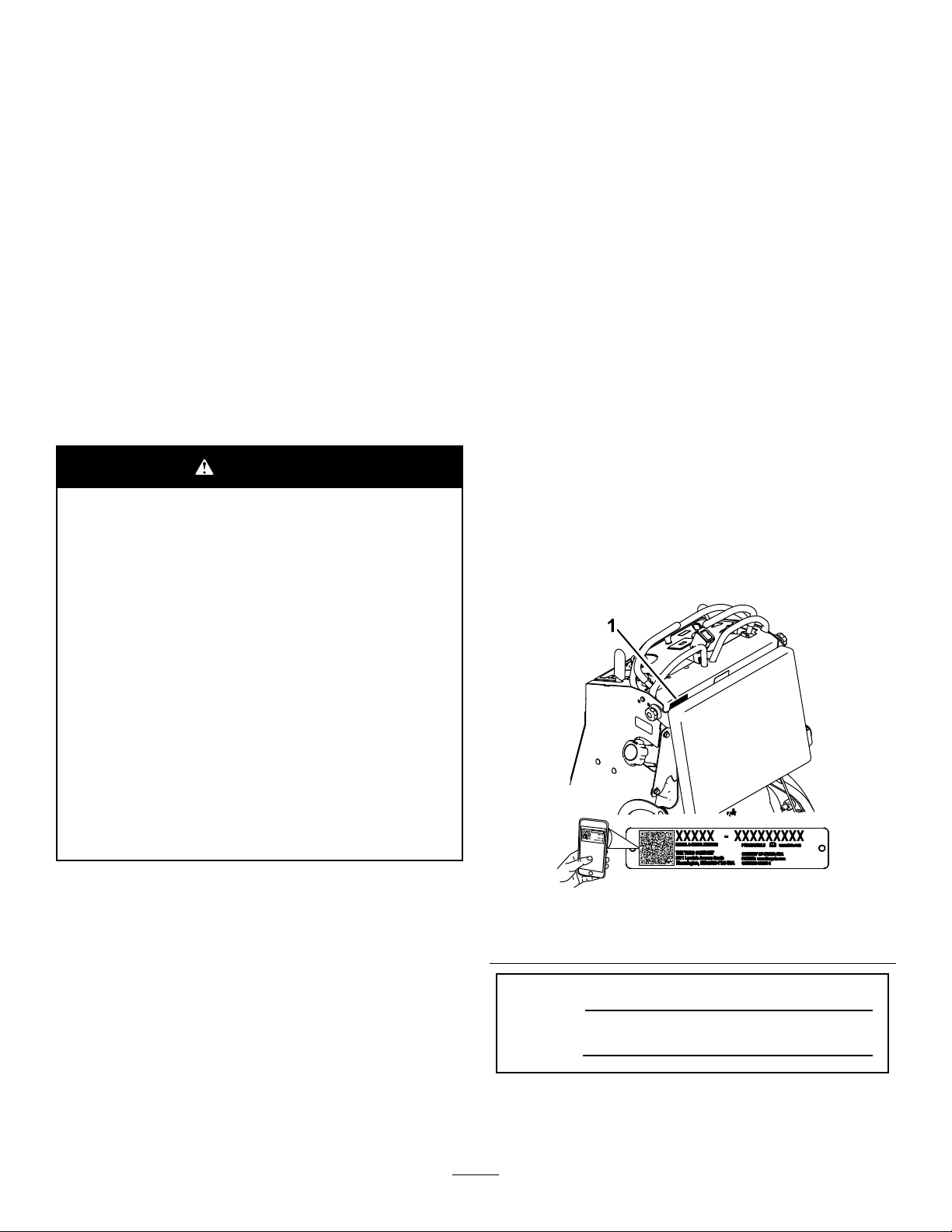
115-4212
1.Hydraulic-uidlevel
2.ReadtheOperator's
Manual.
1.Crushinghazardofhandsorfeet—installthecylinderlock.
3.Warning—donottouchthe
hotsurface.
115-4858
decal116-8775
decal115-4212
1.ReadtheOperator’s
Manual.
decal115-4858
116-8775
2.Filltobottomofllerneck;
warning—donotoverll
thetank.
decal133-5619
133-5619
6
Page 7
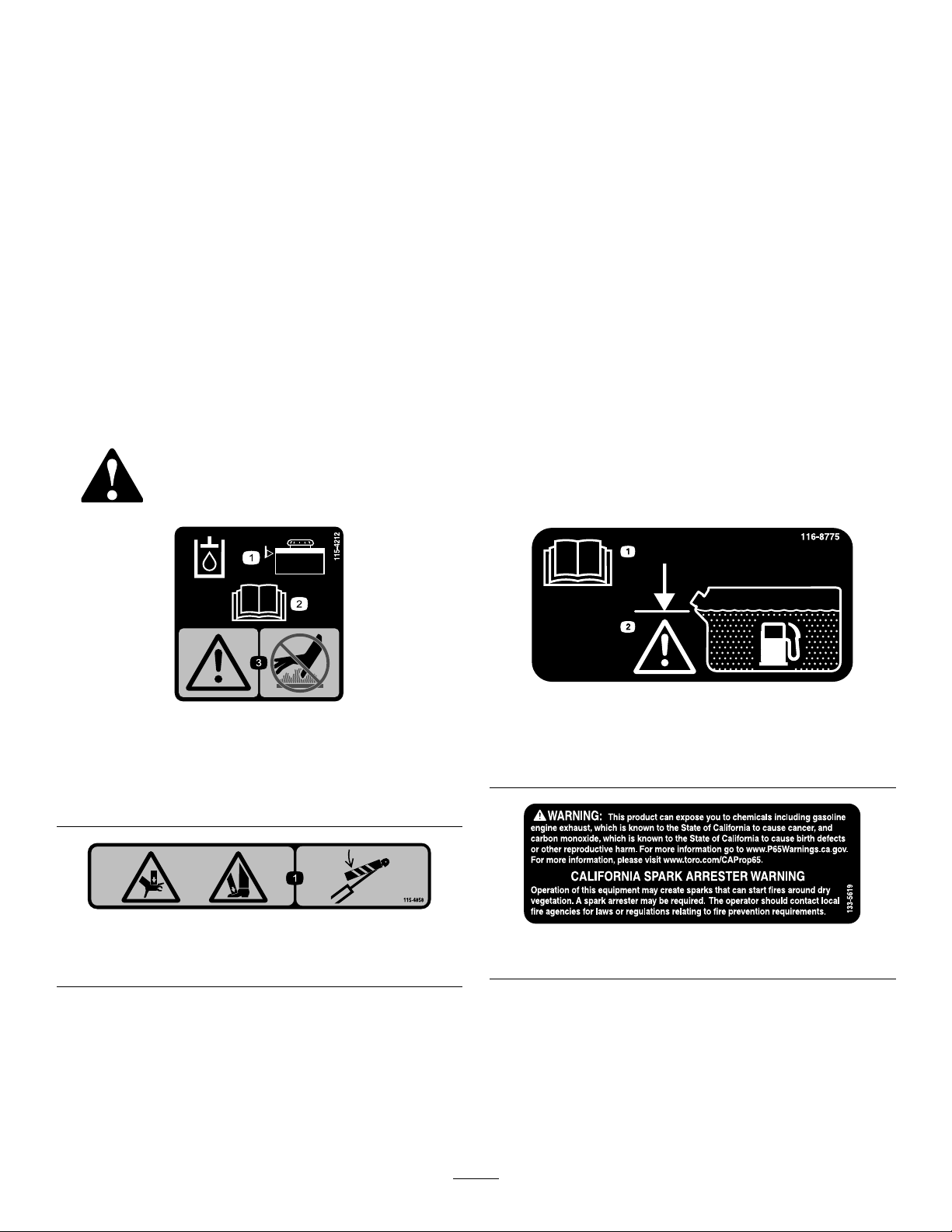
decal132-8961
132-8961
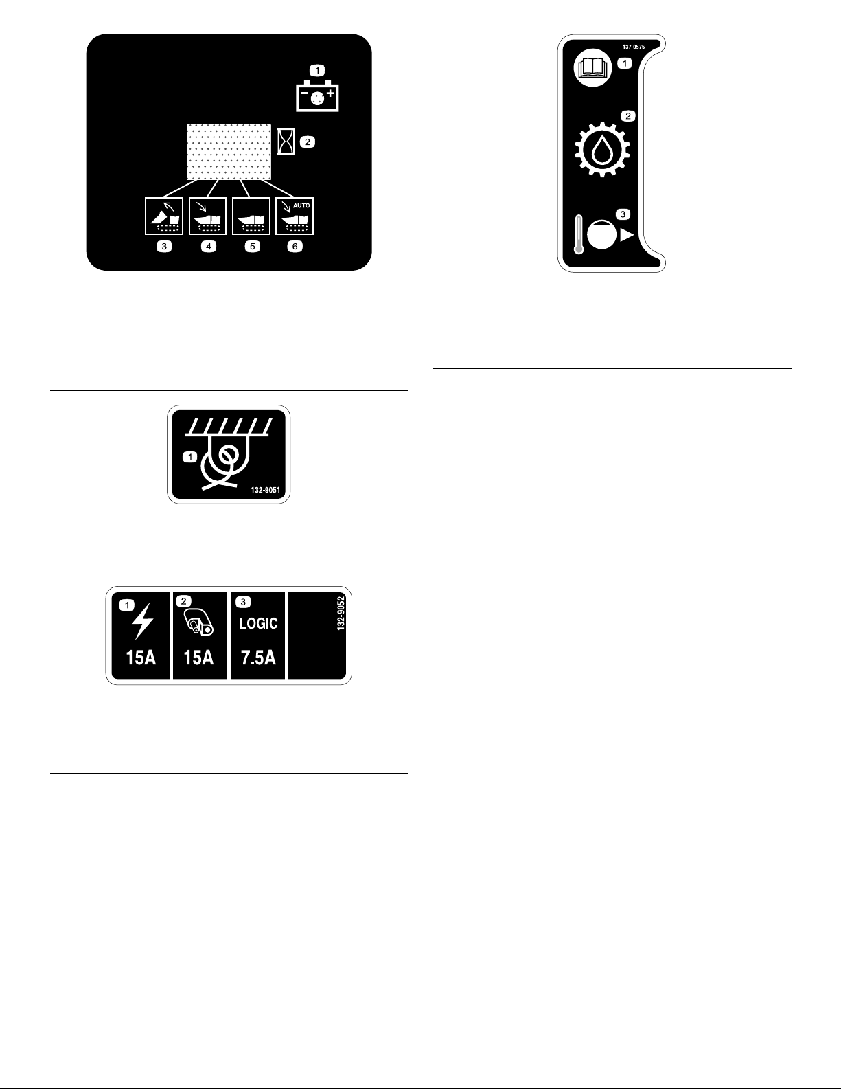
137-0575
decal137-0575
1.Batterychargingcondition4.Hopperislowering.
2.Hourmeter5.Hopperisdown.
3.Hopperisraising.6.Hopperislowering
automatically.
132-9051
1.Tie-downpoint
132-9052
1.ReadtheOperator’s
3.Cold-llline
Manual.
2.Transmissionuid
decal132-9051
decal132-9052
1.Main(15A)3.Logic(7.5A)
2.Auxiliary(15A)
7
Page 8
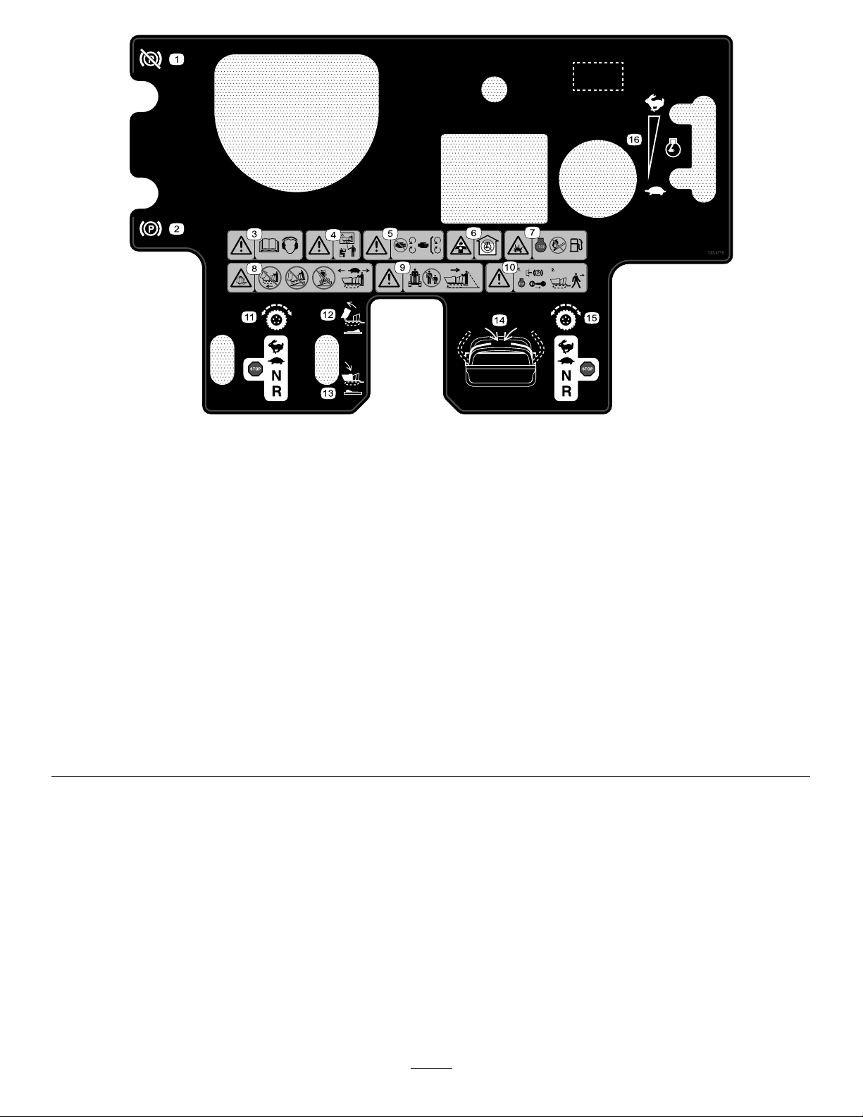
decal137-3715
137-3715
1.Parking-brakerelease
7.Explosionhazard—shutofftheengine
beforeaddingfuel;nore,open
ames,orsmokingwhenaddingfuel.
2.Parkingbrake8.Machinetippinghazard—donotdrive
forwardwiththehopperraised;do
notdrivedownslopeswiththehopper
raised;donotdriveacrossslopeswith
thehopperraised;driveslowlywiththe
hopperdown.
3.Warning—readtheOperator’sManual;
hearingprotectionmustbeworn.
9.Warning—keepbystandersasafe
distanceawayfromthemachine;watch
behindyouwhenmovinginreverse.
4.Warning—alloperatorsshouldbe
trainedbeforeoperatingthemachine.
10.Warning—engagetheparkingbrake,
shutofftheengine,andremovethekey
beforeleavingtheoperator’sposition.
5.Warning-keepawayfrommovingparts;
11.Lefttractioncontrols
keepallguardsandcoversinplace.
6.Poisonousfumesortoxicgases,
12.Raisehopper
asphyxiationhazard—donotrunthe
engineinanenclosedspace.
13.Lowerhopper
14.Movethehandlesintooperate.
15.Righttractioncontrols
16.Engine-speedcontrol
8
Page 9
ProductOverview
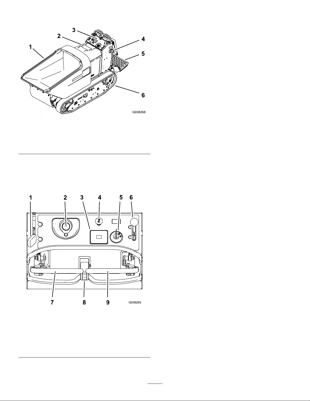
Figure3
1.Hopper4.Fuel-tankcap
2.Hood
3.Controlpanel
Controls
5.Operatorplatform
6.Track
ParkingBrakeLever
Toengagetheparkingbrake,pullbackthelever.
(Figure4).
Todisengagetheparkingbrake,pushthelever
forward.
HourMeter
Thehourmeterrecordsthenumberofhoursthe
enginehasoperated.Itoperateswhentheengine
isrunning.Usethesetimesforschedulingregular
maintenance(Figure4).
ChokeControl
g038268
Usethechoketostartacoldengine.Pullthechoke
knobuptoengageit.Pushthechokeknobdownto
disengageit(Figure4).
KeySwitch
Usethekeyswitchtostarttheengine(Figure4).The
switchhas3positions:OFF,RUN,andSTART.
Becomefamiliarwithallthecontrols(Figure4)before
youstarttheengineandoperatethemachine.
Figure4
1.Parking-brakelever6.Throttlelever
2.Hydraulic-tankcap
3.Hourmeter8.Dumpswitch
4.Chokecontrol
5.Keyswitch
7.Leftmotion-controllever
9.Rightmotion-controllever
ThrottleLever
ThethrottleleverisvariablebetweentheFASTand
SLOWpositions(Figure4).
Motion-ControlLevers
Usethemotion-controlleverstodrivethemachine
forwardandreverseandtoturneitherdirection
(Figure4).
DumpSwitch
Usethedumpswitchtodumpandlowerthehopper.
Ifyouholdtheswitchdown0.2to1.3seconds,the
hopperfullylowersautomatically.
g038269
9
Page 10

Specications
Note:Specicationsanddesignaresubjectto
changewithoutnotice.
Width
Length
Height
Weight
Hoppercapacity
Maximumload
DischargeHeight
90.2cm(35-1/2inches)
268.0cm(105-1/2inches)
121.2cm(47.7inches)
734kg(1,619lb)
0.45m
1,134kg(2,500lb)
38.1cm(15inches)
3
Operation
Note:Determinetheleftandrightsidesofthe
machinefromthenormaloperatingposition.
Important:Beforeoperating,checkthefueland
oillevel,andremovedebrisfromthemachine.
Also,ensurethattheareaisclearofpeopleand
debris.
(16ft3)
AddingFuel
•Forbestresults,useonlyclean,fresh(lessthan
30daysold),unleadedgasolinewithanoctane
ratingof87orhigher((R+M)/2ratingmethod).
Attachments/Accessories
AselectionofT oroapprovedattachmentsand
accessoriesisavailableforusewiththemachine
toenhanceandexpanditscapabilities.Contact
yourAuthorizedServiceDealerorauthorizedT oro
distributororgotowww.Toro.comforalistofall
approvedattachmentsandaccessories.
Toensureoptimumperformanceandcontinuedsafety
certicationofthemachine,useonlygenuineT oro
replacementpartsandaccessories.Replacement
partsandaccessoriesmadebyothermanufacturers
couldbedangerous,andsuchusecouldvoidthe
productwarranty.
•ETHANOL:Gasolinewithupto10%ethanol
(gasohol)or15%MTBE(methyltertiarybutyl
ether)byvolumeisacceptable.Ethanoland
MTBEarenotthesame.Gasolinewith15%
ethanol(E15)byvolumeisnotapprovedforuse.
Neverusegasolinethatcontainsmorethan10%
ethanolbyvolume,suchasE15(contains15%
ethanol),E20(contains20%ethanol),orE85
(containsupto85%ethanol).Usingunapproved
gasolinemaycauseperformanceproblemsand/or
enginedamagewhichmaynotbecoveredunder
warranty.
•Donotusegasolinecontainingmethanol.
•Donotstorefueleitherinthefueltankorfuel
containersoverthewinterunlessyouuseafuel
stabilizer.
•Donotaddoiltogasoline.
10
Page 11

DANGER
DANGER
Incertainconditions,fuelisextremely
ammableandhighlyexplosive.Areor
explosionfromfuelcanburnyouandothers
andcandamageproperty.
•Fillthefueltankoutdoors,inanopenarea,
whentheengineiscold.Wipeupanyfuel
thatspills.
•Neverllthefueltankinsideanenclosed
trailer.
•Donotllthefueltankcompletelyfull.
Addfueltothefueltankuntilthelevelis6
to13mm(1/4to1/2inch)belowthebottom
ofthellerneck.Thisemptyspaceinthe
tankallowsfueltoexpand.
•Neversmokewhenhandlingfuelandstay
awayfromanopenameorwherefuel
fumesmaybeignitedbyaspark.
•Storefuelinanapprovedcontainerand
keepitoutofthereachofchildren.Never
buymorethana30-daysupplyoffuel.
•Donotoperatewithoutentireexhaust
systeminplaceandinproperworking
condition.
Incertainconditionsduringfueling,static
electricitycanbereleasedcausingaspark,
whichcanignitethefuelvapors.Areor
explosionfromfuelcanburnyouandothers
andcandamageproperty.
•Alwaysplacefuelcontainersontheground
awayfromyourvehiclebeforelling.
•Donotllfuelcontainersinsideavehicle
oronatruckortrailerbedbecauseinterior
carpetsorplastictruckbedlinersmay
insulatethecontainerandslowthelossof
anystaticcharge.
•Whenpractical,removefuel-powered
equipmentfromthetruckortrailerand
refueltheequipmentwithitswheelsonthe
ground.
•Ifthisisnotpossible,thenrefuelsuch
equipmentonatruckortrailerfroma
portablecontainerratherthanfroma
fuel-dispensernozzle.
•Ifyoumustuseafuel-dispensernozzle,
keepthenozzleincontactwiththerimof
thefueltankorcontaineropeningatall
timesuntilfuelingiscomplete.
WARNING
Fuelisharmfulorfatalifswallowed.
Long-termexposuretovaporscancause
seriousinjuryandillness.
•Avoidprolongedbreathingofvapors.
•Keepyourfaceawayfromnozzleandfuel
tankorconditioneropening.
•Keepfuelawayfromeyesandskin.
11
Page 12
UsingStabilizer/Conditioner
PerformingDaily
Usefuelstabilizer/conditionerinthemachinetokeep
thefuelfreshlongerwhenusedasdirectedbythe
fuel-stabilizermanufacturer.
Important:Donotusefueladditivescontaining
methanolorethanol.
Addtheamountoffuelstabilizer/conditionertofresh
fuelasdirectedbythefuel-stabilizermanufacturer.
FillingtheFuelTank
Fuel-tankcapacity:40.1L(10.6USgallons)
1.Cleantheareaaroundthefuel-tankcap.
2.Removethecap.
3.Addfueluntilitisatthebottomofthellerneck.
Note:Donotllthefueltankcompletelyfull.
Theemptyspaceinthetankallowsthefuelto
expand.
4.Installthecap.
Maintenance
Beforestartingtheengineeachday ,performthe
followingprocedures:
•Checktheengine-oillevel—refertoCheckingthe
Engine-OilLevel(page20).
•Checkthehydraulic-uidlevelforthedrive
system—refertoCheckingtheHydraulic-Fluid
LevelfortheDriveSystem(page32)
•Checkthehydraulic-uidlevelforthelift
system—refertoCheckingtheHydraulic-Fluid
LevelfortheLiftSystem(page34).
OperatingtheParking Brake
Alwaysengagetheparkingbrakewhenyoustopthe
machineorleaveitunattended.Beforeeachuse,
checktheparkingbrakeforproperoperation.
CAUTION
Figure5
Childrenorbystandersmaybeinjuredifthey
moveorattempttooperatethemachinewhile
itisunattended.
Removetheignitionkeyandengagethe
parkingbrakewheneveryouleavethe
machineunattended.
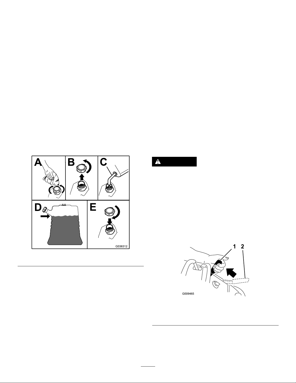
EngagingtheParkingBrake
Pulltheparking-brakeleverrearwardintothe
ENGAGEDposition(Figure6).
g038312
g009465
Figure6
1.Parkingbrake—ENGAGED
position
2.Parkingbrake—RELEASED
position
ReleasingtheParkingBrake
Pushtheparking-brakeleverforward(Figure6).
12
Page 13

OperatingtheThrottle
StartingtheEngine
ThethrottlecontrolmovesbetweenFASTandSLOW
positions(Figure7).
AlwaysusetheFASTpositionwhenmovingthe
machine.
Figure7
OperatingtheChoke
Usethechoketostartacoldengine.
1.Pullupthechokeknobtoengagethechoke
beforeusingthekeyswitch(Figure8).
1.Engagetheparkingbrake.
2.Engagethechoke.
Note:Awarmorhotenginemaynotrequire
choking.Youmayneedtorepeatthestarting
cyclewhenyoustarttheengineforthersttime
afteryouhavelledacompletelyemptyfuel
systemwithfuel.
3.MovethethrottlebetweentheFASTandSLOW
positions.
4.TurnthekeyswitchtotheSTARTposition.
g008946
5.Whentheenginestarts,disengagethechoke.
Important:Donotengagethestarterformore
than5secondsatatime.Iftheenginefailstostart,
allowa15-secondcool-downperiodbetween
attempts.Failuretofollowtheseinstructionscan
burnoutthestarter.
Note:Ensurethatyoufullyengagethechoke.
Youmayneedtoholdtheknobupwhenyou
usethekeyswitch.
2.Pushdownthechoketodisengagethechoke
aftertheenginehasstarted(Figure8).
g038313
Figure9
Figure8
1.ONposition2.OFFposition
g008959
13
Page 14

ShuttingOfftheEngine
1.MovethethrottlebetweentheFASTandSLOW
positions.
2.Engagetheparkingbrake.
3.TurnthekeyswitchtotheOFFpositionand
removethekey.
Figure10
OperatingtheHopper
Hoppercapacity:1134kg(2,500lb)
RemovingDebrisfromthe Machine
1.Parkthemachineonalevelsurface,move
themotion-controlleverstotheNEUTRAL-LOCK
position,engagetheparkingbrake,andlower
thehopper.
2.Shutofftheengineandremovethekey.Allow
theenginetocool.
3.Cleantheinsideofthehopperusingahose.
Important:Donotuseahammertoremove
materialfromtheinsideofthehopper;this
maycausedamagetothemachine.
4.Cleananydebrisfromunderthehopper.
5.Wipeawaydebrisfromtheaircleaner.
6.Cleananydebrisbuildupontheengineandin
thetransmissionwithabrushorblower.
g038314
Important:Blowoutdirtratherthanwash
itout.Ifyouusewater,keepitawayfrom
electricalpartsandhydraulicvalves.Donot
useahigh-pressurewasher.High-pressure
washingcandamagetheelectricalsystem
andhydraulicvalvesordepletegrease.
Knowtheloadcapacityofthemachineandnever
exceedit.Thismachinenormallyoperatesonuneven,
unpaved,bumpy,and/orinclinedsurfaces—adjustthe
loadaccordingly.
1.Positionthemachinewhereyouintendtodump
theload.
2.Dumpthehopperbypushingthetopofthe
dumpswitch(Figure11).
3.Lowerthehopperbypushingthebottomofthe
dumpswitch(Figure11).
Note:Ifyouholdthebottomoftheswitch
0.2to1.3seconds,thehopperfullylowers
automatically.
Figure11
1.Dumpthehopper .2.Lowerthehopper .
g038270
14
Page 15

LoweringtheHopper
TransportingtheMachine
withoutPower
1.Installthecylinderlock;refertoInstallingthe
CylinderLock(page18).
2.Ensurethatthetubisempty.
3.Placealargedrainpanunderthe
hydraulic-manifoldblock(Figure12).
Figure12
1.Hydraulic-manifoldblock
4.Disconnectthehosettingsinthemanifold
blockandallowtheuidtodrainintothepain.
Note:Disposeoftheuseduidatacertied
recyclingcenter.
Useaheavy-dutytrailerortruckwithfull-widthramps
totransportthemachine.Ensurethatthetraileror
truckhasallthenecessarybrakes,lighting,and
markingasrequiredbylaw.Pleasecarefullyreadall
thesafetyinstructions.Knowingthisinformationcould
helpyou,yourfamily,petsorbystandersavoidinjury.
Refertoyourlocalordinancesfortrailerandtie-down
requirements.
Important:Donotoperateordrivethemachine
onroadways.
1.Lowerthehopper.
2.Ifusingatrailer,connectittothetowingvehicle
andconnectthesafetychains.
3.Ifapplicable,connectthetrailerbrakes.
g186548
4.Carefullyloadthemachineontothetraileror
truck.
5.Shutofftheengine,removethekey ,andset
thebrake.
6.Usethemetaltie-downloopsonthemachineto
securelyfastenthemachinetothetrailerortruck
withstraps,chains,cable,orropes(Figure13).
5.Connectthehosettings.
6.Useahoistorhave2peopleholdupthehopper
andremovethecylinderlock.
7.Carefullylowerthehoppertothemachineframe.
Figure13
1.Fronttie-downloops2.Reartie-downloops
15
g185890
Page 16

LiftingtheMachine
Hoistthemachineusing2liftpointsunderthehopper
and2reartie-downloops.Tiltthehopperforwardto
locatethe2liftloopsandattachachainorstrapsat
eachoftheloopsasshowninFigure14.
Note:Takeuptheslackinthechainorstrapsto
properlybalancetheunit.
1.Liftpointsunderhopper
g194436
Figure14
2.Reartie-downloops
16
Page 17

Maintenance
Note:Determinetheleftandrightsidesofthemachinefromthenormaloperatingposition.
RecommendedMaintenanceSchedule(s)
MaintenanceService
Interval
Aftertherst10hours
Beforeeachuseordaily
Every25hours
Every40hours
Every50hours
Every100hours
MaintenanceProcedure
•Checkandadjustthetracktension(every10hoursuntil50hours).
•Checktheengine-oillevel.
•Cleantheblowerhousing(moreoftenunderextremelydusty,dirtyconditions).
•Checktheconditionofthetrack.
•Checktheparkingbrakeoperation.
•Checkthehydraulic-uidlevelforthedrivesystem.
•Checkthehydraulic-uidlevelfortheliftsystem.
•Removedebrisfromthemachine.
•Checkforloosefasteners.
•Serviceorreplacetheair-cleanerfoamelement(moreoftenunderextremelydusty,
dirtyconditions).
•Checkthehydrauliclinesforleaks,loosettings,kinkedlines,loosemounting
supports,wear,anddeterioration.
•Greasethemachine(greaseimmediatelyaftereverywashing).
•Checkthebattery.
•Checkandadjustthetracktension.
•Replacetheair-cleanerpaperelement(moreoftenunderextremelydusty ,dirty
conditions).
•Changetheengineoilandtheengine-oillter.
•Checkthesparkplug.
•Removethecoolingshroudsandcleanthecoolingareas(moreoftenunder
extremelydusty,dirtyconditions).
•Replacethefuellter(moreoftenunderdusty ,dirtyconditions).
•Inspectthedrivebelt.
•Cleandirtbuildupinthechassis.
•Replacethesparkplug.
•Checktheroadwheels.
Every300hours
•Replacethedrivebelt.
•Changethehydraulicuidandlterforthedrivesystem.
•Changethehydraulicuidfortheliftsystem.
•Replacethehydrauliclterfortheliftsystem.
Important:Refertoyourengineowner'smanualforadditionalmaintenanceprocedures.
CAUTION
Ifyouleavethekeyintheswitch,someonecouldaccidentlystarttheengineandseriously
injureyouorotherbystanders.
Removethekeyfromtheswitchbeforeyouperformanymaintenance.
17
Page 18

Pre-Maintenance
Procedures
ReleasingtheCushionfor RearAccess
Youcanreleasethecushionforrearaccesstothe
machineformaintenanceoradjustment.
1.Lowertheplatform.
2.Loosenthetwistknobsoneachsideofthe
machine(Figure15).
Figure15
g185887
Figure16
1.Cylinderlock2.Lift-cylinderrod
4.Slowlylowerthehopperuntilthecylinderlock
contactsthecylinderbodyandrodend.
g032556
RemovingandStoringthe
1.Twistknob
3.Removethecushionandlowerittotheplatform.
4.Performanymaintenanceoradjustmentonthe
machine.
5.Raisethecushion,andslideitontothepinson
bothsidesofthemachine.
6.Tightenthetwistknobs.
2.Cushion
UsingtheCylinderLock
InstallingtheCylinderLock
1.Parkthemachineonalevelsurface,move
themotion-controlleverstotheNEUTRAL-LOCK
position,engagetheparkingbrake,andfully
raisethehopper.
2.Removethe2cotterlesspinssecuringthe
cylinderlocktothemachine.
3.Slidethecylinderlockoverthelift-cylinderrod
andsecurewiththecotterlesspins(Figure16).
CylinderLock
Important:Removethecylinderlockfromthe
lift-cylinderrodandfullysecureitinthestorage
positionbeforeoperatingthemachine.
1.Startthemachine.
2.Fullyraisethehopper.
3.Shutofftheengine.
4.Removethecotterlesspinssecuringthecylinder
lock.
5.Placethecylinderlockonthepostsinsidethe
machineframeandsecurewiththecotterless
pins.
6.Lowerthehopper.
18
Page 19

Lubrication
EngineMaintenance
GreasingtheMachine
ServiceInterval:Every50hours
Whenoperatingthemachineundernormalconditions,
lubricateallgreasettingsforthebearingsand
bushingswithNo.2lithiumgrease.Lubricatethe
bearingsandbushingsimmediatelyafterevery
washing,regardlessoftheintervallisted.Applyalight
coatingofoilontothecontrolcables.
Cylinderpivots(2)—Figure17
ServicingtheAirCleaner
ServiceInterval:Every25hours—Serviceorreplace
theair-cleanerfoamelement(more
oftenunderextremelydusty,dirty
conditions).
Every100hours—Replacetheair-cleaner
paperelement(moreoftenunderextremely
dusty,dirtyconditions).
Note:Operatingtheenginewithlooseordamaged
air-cleanercomponentscouldallowunlteredairinto
theengine,causingprematurewearandfailure.
Note:Servicetheaircleanermoreoftenunder
extremelydusty,dirtyconditions.
RemovingtheElements
1.Rotatethelatchesoutward.
2.Removethecovertoaccesstheair-cleaner
elements(Figure18).
Figure17
g019608
g243624
Figure18
1.Air-cleanercover2.Air-cleanerlatch
3.Removethefoamandpaperelements(Figure
19).
4.Removethefoamelementfromthepaper
element(Figure19).
19
Page 20

Figure19
1.Air-cleanercover3.Paperelement
2.Foamelement
ServicingtheFoamElement
1.Washthefoamelementinwarmwaterand
detergent.
2.Rinseandallowittoairdry.
3.Lightlyoilthefoamelementwithnewoiland
squeezeoutexcessoil.
CheckingtheEngine-Oil Level
ServiceInterval:Beforeeachuseordaily
Important:Remembertoadd80%oftheoil,
andthengraduallyllittotheFullmarkonthe
dipstick.
Important:Donotruntheenginewiththeoil
g028106
levelabovetheFullmarkorbelowthelowmark.
Otherwise,youmaydamagetheengine.
1.Parkthemachineonalevelsurface,move
themotion-controlleverstotheNEUTRAL-LOCK
position,engagetheparkingbrake,andlower
thehopper.
2.Shutofftheengine,andremovethekey.Allow
theenginetocool.
3.Openthecowl.
4.Checktheengine-oillevelasshowninFigure
20.
ServicingthePaperElement
1.Gentlytapthepaperelementtodislodgedirt.
Note:Donotwashthepaperelementoruse
pressurizedair,asthisdamagestheelement.
Note:Replaceadirty,bent,ordamaged
element.Handlethenewelementcarefully;
donotuseifthesealingsurfacesarebentor
damaged.
2.Cleantheair-cleanerbaseasrequired,and
checkthecondition.
InstallingtheElements
1.Installthefoamelementontothepaperelement.
2.Installtheelementsontotheair-cleanerbase
(Figure19).
3.Installthecover,andsecureitwiththelatches
(Figure18).
g243578
Figure20
20
Page 21

ChangingtheEngineOil andFilter
ServiceInterval:Every100hours
OilType::Detergentoil(APIserviceSJorhigher)
EngineOilCapacity:1.9L(64oz)
Viscosity:Refertothetablebelow.
Figure21
Changetheengineoilwhiletheengineiswarm.
Note:Disposeoftheusedoilatarecyclingcenter.
1.Parkthemachineonalevelsurface,move
themotion-controlleverstotheNEUTRAL-LOCK
position,engagetheparkingbrake,raisethe
hopper,andinstallthecylinderlock.
g185888
g031623
Figure22
g017552
B.Installthedrainplug(Figure22).T orquethe
plugto13.6N∙m(10ft-lb).
4.Changetheengine-oillterasshowninFigure
23.
2.Shutofftheengineandremovethekey.
3.Performthefollowingstepstochangethe
engineoil:
A.Removethedrainplugandallowallofthe
existingoiltodrainoutoftheengine(Figure
22).
21
Page 22

Figure23
5.Slowlypourapproximately80%ofthespecied
oilintothellertube(Figure24).
g243623
Figure24
g027477
ServicingtheSparkPlugs
ServiceInterval:Every100hours—Checkthespark
plug.
Every300hours—Replacethesparkplug.
ThesparkplugsareRFIcompliant.Equivalent
alternatebrandplugscanalsobeused.
Type:ChampionXC12YC
AirGap:0.76mm(0.03inch)
22
Page 23

RemovingtheSparkPlug
1.Parkthemachineonalevelsurface,move
themotion-controlleverstotheNEUTRAL-LOCK
position,engagetheparkingbrake,andlower
thehopper.
2.Shutofftheengineandremovethekey.Allow
theenginetocool.
3.Beforeremovingthesparkplug(s),cleanthe
areaaroundthebaseoftheplugtokeepdirt
anddebrisoutoftheengine.
4.Removethesparkplug(Figure25).
g027478
Figure25
CheckingtheSparkPlug
Important:Donotcleanthesparkplug(s).
Alwaysreplacethesparkplug(s)whenithas:a
blackcoating,wornelectrodes,anoilylm,or
cracks.
Note:Ifyouseelightbrownorgrayontheinsulator,
theengineisoperatingproperly.Ablackcoatingon
theinsulatorusuallymeanstheaircleanerisdirty.
Setthegapto0.76mm(0.03inch).
InstallingtheSparkPlug
g028109
Figure27
Important:Ensurethatthesparkplugis
tightenedtothecorrecttorquespecication.A
loosesparkplugmaycausethecylinderheadto
overheat,whileanovertightenedsparkplugmay
causedamagetothethreadsinthecylinderhead.
CleaningtheBlower Housing
Every100hours/Yearly(whichevercomesrst)
Toensurepropercooling,ensurethatthegrass
screen,coolingns,andotherexternalsurfacesofthe
enginearekeptcleanatalltimes.
Figure26
Ensurethatthecoolingshroudsareinstalled.
Important:Operatingtheenginewithablocked
grassscreen,dirtyorpluggedcoolingns,and/or
coolingshroudsremovedcausesenginedamage
duetooverheating.
g027479
23
Page 24

FuelSystem
DrainingtheFuelTank
Maintenance
ReplacingtheFuelFilter
ServiceInterval:Every100hours/Yearly(whichever
comesrst)(moreoftenunder
dusty,dirtyconditions).
1.Parkthemachineonalevelsurface,move
themotion-controlleverstotheNEUTRAL-LOCK
position,engagetheparkingbrake,andlower
thehopper.
2.Shutofftheengine,andremovethekey.Allow
theenginetocool.
3.ReplacethefuellterasshowninFigure28.
Youcandrainthefueltankbyremovingitandpouring
thefueloutofthellneck;refertoRemovingtheFuel
Tank(page25).Youcanalsodrainthefueltankby
usingasiphoninthefollowingprocedure.
DANGER
Incertainconditions,fuelisextremely
ammableandhighlyexplosive.Areor
explosionfromfuelcanburnyouandothers
andcandamageproperty.
•Drainfuelfromthefueltankwhenthe
engineiscold.Dothisoutdoorsinanopen
area.Wipeupanyfuelthatspills.
•Neversmokewhendrainingfuelandstay
awayfromanopename,orwhereaspark
mayignitethefuelfumes.
1.Parkthemachineonalevelsurface,move
themotion-controlleverstotheNEUTRAL-LOCK
position,engagetheparkingbrake,andlower
thehopper.
g185888
2.Shutofftheengine,andremovethekey.Allow
theenginetocool.
3.Cleanaroundthefuelcaptopreventdebrisfrom
gettingintothefueltank(Figure29).
4.Removethefuelcap.
5.Insertasyphonpumpintothefueltank.
6.Usingthesyphonpump,drainthefuelintoa
cleanfuelcan(Figure29).
7.Wipeupanyspilledfuel.
Figure29
1.Fuelcap
g186224
Figure28
g027753
24
Page 25

RemovingtheFuelTank
1.Lowertheplatform.
2.Releasethecushion;refertoReleasingthe
CushionforRearAccess(page18).
3.Removethecrossbracket(Figure30).
ElectricalSystem
Maintenance
ServicingtheBattery
ServiceInterval:Every50hours
DANGER
Batteryelectrolytecontainssulfuricacid,
whichisfatalifconsumedandcausessevere
burns.
Donotdrinkelectrolyteandavoidcontact
withskin,eyesorclothing.Wearsafety
glassestoshieldyoureyesandrubbergloves
toprotectyourhands.
Figure30
1.Fueltank
4.Removethefueltankandsetitontheoperator
platform.
Note:Ifyouwanttomovethefueltankfurther
fromthemachine,removethefuelandvent
linesfromthetopofthetank.
2.Crossbracket
g186223
RemovingtheBattery
WARNING
Batteryterminalsormetaltoolscouldshort
againstmetalmachinecomponents,causing
sparks.Sparkscancausethebatterygasses
toexplode,resultinginpersonalinjury.
•Whenremovingorinstallingthebattery,
donotallowthebatteryterminalstotouch
anymetalpartsofthemachine.
•Donotallowmetaltoolstoshortbetween
thebatteryterminalsandmetalpartsofthe
machine.
WARNING
Incorrectbattery-cableroutingcoulddamage
themachineandcables,causingsparks.
Sparkscancausethebatterygassesto
explode,resultinginpersonalinjury.
•Alwaysdisconnectthenegative(black)
batterycablebeforedisconnectingthe
positive(red)cable.
•Alwaysconnectthepositive(red)battery
cablebeforeconnectingthenegative
(black)cable.
1.Parkthemachineonalevelsurface,move
themotion-controlleverstotheNEUTRAL-LOCK
position,engagetheparkingbrake,andlower
thehopper.
2.Shutofftheengine,andremovethekey.Allow
theenginetocool.
3.Removethenegativebatterycablefromthe
battery(Figure31).
25
Page 26

Figure31
1.Positivebatterycable
2.Securingrod
3.Wingnut(2)
4.Negativebatterycable
4.Removethepositivebatterycablefromthe
battery(Figure31).
5.Removethe2wingnuts,securingrod,andthe
battery(Figure31).
InstallingtheBattery
1.Placethebatteryontheplatformandsecure
itusingthe2wingnutsandthesecuringrod
(Figure31).
2.Installthepositivebatterycabletothebattery
(Figure31).
3.Installthenegativebatterycabletothebattery
(Figure31).
ChargingtheBattery
WARNING
Chargingthebatteryproducesgassesthat
canexplode.
Neversmokenearthebatteryandkeepsparks
andamesawayfrombattery .
Important:Alwayskeepthebatteryfullycharged
(1.265specicgravity)topreventbatterydamage
g185906
whenthetemperatureisbelow0°C(32°F).
1.Removethebatteryfromthechassis;referto
RemovingtheBattery(page25).
2.Performthefollowingstepstocheckthe
electrolytelevel:
A.Ensurethatthecellcoversarefreefromdirt
anddebris.
Important:Dirtanddebristhatenters
thebatterycellscausesdamagetothe
battery.
B.Removethecoversfromthetopofthecells.
C.Ensurethattheelectrolytesolutioncovers
theleadplates.Usedistilledwatertotopoff
thesolutionlevel,ifneeded.
3.Ensurethatthellercapsareinstalledonthe
battery.
4.Chargethebatteryfor1hourat25to30Aor6
hoursat4to6A.
5.Whenthebatteryisfullycharged,unplugthe
chargerfromtheelectricaloutlet,anddisconnect
thechargerleadsfromthebatteryposts(Figure
32).
6.Installthebatteryontothemachineandconnect
thebatterycables;refertoInstallingtheBattery
(page26).
1.Positivebatterypost
2.Negativebatterypost
26
Note:Donotrunthemachinewiththebattery
disconnected;electricaldamagemayoccur.
g000538
Figure32
3.Red(+)chargerlead
4.Black(-)chargerlead
Page 27

ServicingtheFuses
DriveSystem
Theelectricalsystemisprotectedbyfusesand
requiresnomaintenance.Ifafuseblows,checkthe
componentorcircuitforamalfunctionorshort.
1.Releasethecushionfromtherearofthe
machine.
2.Pulloutthefusetoremoveorreplaceit(Figure
33).
3.Installthecushiontotherearofthemachine.
Note:Ensurethatthecorrect-sizefuseis
installed(Figure33).
Maintenance
ServicingtheTracks
ServiceInterval:Beforeeachuseordaily—Check
theconditionofthetrack.
Aftertherst10hours—Checkandadjustthe
tracktension(every10hoursuntil50hours).
Every50hours—Checkandadjustthetrack
tension.
Every300hours—Checktheroadwheels.
CleaningtheTracks
1.Parkthemachineonalevelsurface,move
themotion-controlleverstotheNEUTRAL-LOCK
position,engagetheparkingbrake,andlower
thehopper.
2.Shutofftheengine,andremovethekey.Allow
theenginetocool.
3.Lift/supportthesideofthemachinetobeworked
onsothatthetrackis3to4inches(7.6to10
cm)offtheground.
Figure33
1.Mainpowerfuse(15A)3.Logicfuse(7.5A)
2.Auxiliarypowerfuse(15
A)
g189366
4.Usingawaterhoseorpressurewasher,remove
dirtfromeachtracksystem.
Important:Ensurethatyouusehigh-pressure
watertowashonlythetrackarea.Donotuse
ahigh-pressurewashertocleantherestofthe
machine.Donotusehigh-pressurewaterbetween
thedrivesprocketandthemachineoryoumay
damagethemotorseals.High-pressurewashing
candamagetheelectricalsystemandhydraulic
valvesordepletegrease.
Important:Ensurethatyoufullycleantheroad
wheels,thefrontwheel,andthedrivesprocket
(Figure34).Theroadwheelsshouldrotatefreely
whenclean.
g186007
Figure34
1.Frontwheel3.Roadwheel
2.Track4.Drivesprocket
27
Page 28

AdjustingtheTrackTension
Ifyouplacethetabofthetensioningtoolalongthe
rearedgeofthetensionnut,theotherendofthe
tensioningtoolshouldalignwiththeedgeofthe
tensionarmasshowninFigure35.Ifthedistanceis
notcorrect,adjustthetracktensionusingthefollowing
procedure:
4.Raisethemachinesothatthetracksareoffthe
ground.
5.Cleanthedrivesprocket,thefrontwheel,and
theroadwheels.Theroadwheelsshouldspin
freelywhenclean.
6.Removethebolt(1/4x1-5/8inch),spacer,and
nut(Figure35).
Note:Ifthetensioningtoolisnotavailable,the
distancebetweenthenutandedgeofthetensionarm
shouldbe7.1cm(2-13/16inch).
Figure35
LeftTrackShown
1.Tensionnut
2.Tensioningtool(equalto
7.1cmor2-13/16inch)
3.Tensioningbolt7.Tab
4.Bolt(1/4x1-5/8inch)
5.Spacer
6.Nut
8.Tensionarm
7.Turnthetensioningbolttoadjustthedistance
betweenthetensionnutandtheendtangent
ofthetensiontubeuntilthedistanceiscorrect,
asshowninFigure35.
8.Aligntheclosestnotchinthetensioningbolt
totheboltholeandsecurethetensioningbolt
withthebolt(1/4x1-5/8inch),spacer,andnut
(Figure35).
ReplacingtheTracks
Replacethetrackswhentheyarebadlyworn.
1.Parkthemachineonalevelsurface,move
themotion-controlleverstotheNEUTRAL-LOCK
position,engagetheparkingbrake,andlower
thehopper.
2.Shutofftheengine,andremovethekey.Allow
theenginetocool.
3.Lift/supportthesideofthemachinetobeworked
g202806
onsothatthetrackis3to4inches(7.6to10
cm)offtheground.
4.Removetheretainingboltforthetensioning
screw.
5.Releasethedrivetensionbyturningthe
tensioningscrewclockwise(Figure35and
Figure36).
1.Parkthemachineonalevelsurface,move
themotion-controlleverstotheNEUTRAL-LOCK
position,engagetheparkingbrake,andlower
thehopper.
2.Shutofftheengine,andremovethekey.Allow
theenginetocool.
3.Cleanthetrackswithhigh-pressurewater.
Important:Ensurethatyouuse
high-pressurewatertowashonlythetrack
area.Donotuseahigh-pressurewasher
tocleantherestofthemachine.Donot
usehighpressurewaterbetweenthedrive
sprocketandthemachineoryoumay
damagethemotorseals.High-pressure
washingcandamagetheelectricalsystem
andhydraulicvalvesordepletegrease.
g186008
Figure36
1.Frontwheel4.Roadwheel
2.Track5.Drivesprocket
3.Tensioningscrewand
retainingbolt
6.Removethetrackatthetopofthefrontwheel,
peelingitoffthewheelwhilerotatingthetrack
forward.
7.Whenthetrackisoffthefrontwheel,removeit
fromthedrivesprocketandroadwheels(Figure
36).
28
Page 29

8.Inspecttheconditionofthewheels.Ifthewheels
showsignsofwear,replacethematthistime.
9.Beginningatthedrivesprocket,coilthenew
trackaroundthesprocket,ensuringthatthe
lugsonthetracktbetweenthespacersonthe
sprocket(Figure36).
10.Pushthetrackunderthelugsandbetweenthe
roadwheels(Figure36).
11.Startingatthebottomofthefrontwheel,install
thetrackaroundthewheelbyrotatingthetrack
rearwardwhilepushingthelugsintothewheel.
12.T ensionthetrack;refertoAdjustingtheTrack
Tension(page28).
13.Lowerthemachinetotheground.
14.Repeatsteps3through13toreplacetheother
track.
ServicingtheDriveBelt
InspectingtheDriveBelt
ReplacingtheDriveBelt
ServiceInterval:Every300hours
1.Parkthemachineonalevelsurface,move
themotion-controlleverstotheNEUTRAL-LOCK
position,engagetheparkingbrake,andlower
thehopper.
2.Shutofftheengine,andremovethekey .Allow
theenginetocool.
3.Releasethecushionandremovethefueltank;
refertoRemovingtheFuelTank(page25).
4.Raisetherearofthemachineandsupportthe
machineonjackstands.
5.Removetheskidplate(Figure35).
ServiceInterval:Every100hours
1.Parkthemachineonalevelsurface,move
themotion-controlleverstotheNEUTRAL-LOCK
position,engagetheparkingbrake,andlower
thehopper.
2.Shutofftheengine,andremovethekey .Allow
theenginetocool.
3.Releasethecushionandremovethefueltank;
refertoReleasingtheCushionforRearAccess
(page18).
4.Inspectthebelt(Figure37).Replacethebelt
ifitisworn;refertoReplacingtheDriveBelt
(page29).
Note:Thesignsofawornbeltinclude
squealingwhilethebeltisrotating,frayededges,
burnmarks,andcracksonthebelt.
g203662
Figure38
1.Rearbolt(2)3.Sidebolt(4)
2.Skidplate
6.Removetheextensionspring(Figure37).
7.Removethe2boltsand2nutsandloosenthe
2setscrewsonthecoupler.Removethegear
pumpfromthepumpmount(Figure39).
Note:Youdonotneedtoremovethettings
fromthepump.
Figure37
1.Extensionspring2.Belt
g189546
29
Page 30

Figure39
1.Bolt(2)3.Gearpump
2.Pumpmount
4.Nut(2)
ControlsSystem
Maintenance
Adjustingthe Motion-ControlLevers
Ifthemotion-controlleversdonotalignhorizontally ,
adjusttherightsidemotion-controllever.
1.Parkthemachineonalevelsurface,lowerthe
hopper,engagetheparkingbrake,shutoffthe
engine,andremovethekey.
2.Pushthemotion-controlleversdownoutofthe
NEUTRAL-LOCKposition(Figure41).
3.Checkiftherightmotion-controlleveraligns
g189559
horizontallywiththeleftmotion-controllever
(Figure41).
8.Removethedrivebeltfromtheenginepulley
and2transmissionpulleys.
Figure40
1.Enginepulley
2.Idlerpulley
3.Transmissionpulley(2)
4.Belt
9.Routethenewbeltaroundtheenginepulleyand
2transmissionpulleys(Figure40).
g009436
Figure41
1.Leftmotion-controllever3.Checkthehorizontal
2.Rightmotion-controllever
intheNeutral-lockposition
alignmenthere
4.Rightmotion-controllever
4.T oadjustthemotion-controllevershorizontally,
youmustadjustthecam.
g189571
5.Releasethecushionfromtherearofthe
machine.
6.Loosenthenutholdingthecam(Figure42).
10.Installthegearpump(Figure39).
11.Installtheextensionspring(Figure37).
12.Installthefueltank;refertoRemovingtheFuel
Tank(page25).
13.Raisethecushion.
30
Page 31

4.Releasetheparkingbrake.
5.Movethemotion-controlleversforward.
Note:Themachineshouldmoveforward.
Note:Ifthemachinedoesnotmoveforward,
refertoAdjustingtheParkingBrake(page31).
6.Engagetheparkingbrakeandshutoffthe
machine.
Figure42
1.Cam
7.Adjustthecamuntilitalignswiththeleft
motion-controlleverandtightenthenutforthe
cam.
2.Nut
Note:Movingthecamclockwise(inthevertical
position)lowersthehandle;movingthecam
counterclockwise(intheverticalposition)raises
thehandle.
Important:Ensurethattheatportionofthe
camdoesnotgoaboveaverticalposition
(rightorleft);otherwiseyoumaydamagethe
switch.
8.Repeatsteps2through7fortheleft
motion-controllever.
BrakeMaintenance
WARNING
Ifthebrakesarenotproperlyadjusted,
seriousinjury,ordeath,mayoccur.
Checkyourbrakesdaily .Ifyouencounterany
problemswiththebrakeswhileoperatingthe
machine,stopthemachineimmediatelyand
bringittoanAuthorizedServiceDealerfor
repair.
g189389
1.Removethefueltank;refertoReleasingthe
CushionforRearAccess(page18).
2.Insidetheleftsideofthecontroltower,adjust
thenutsuntilthecablesaretaught(Figure43).
Figure43
1.Cable
3.Installthefueltank,crossbracket,andcushion.
2.Nuts
g186011
AdjustingtheParkingBrake
CheckingtheParkingBrake
ServiceInterval:Beforeeachuseordaily
1.Parkthemachineonalevelsurface,lowerthe
hopper,andengagetheparkingbrake.
2.Starttheengineandmovethethrottleleverto
theFASTposition.
3.Movethemotion-controlleversforward.
Note:Themachineshouldnotmoveforward.
Note:Ifthemachinemovesforward,referto
AdjustingtheParkingBrake(page31).
31
Page 32

HydraulicSystem
Maintenance
WARNING
Hydraulicuidescapingunderpressurecan
penetrateskinandcauseinjury.Fluidinjected
intotheskinmustbesurgicallyremoved
withinafewhoursbyadoctorfamiliarwith
thisformofinjury;otherwisegangrenemay
result.
•Keepyourbodyandhandsawayfrom
pinholeleaksornozzlesthateject
high-pressurehydraulicuid.
•Usecardboardorpapertondhydraulic
leaks;neveruseyourhands.
ServicingtheHydraulic
Figure44
1.Expansion-tankcap
2.Sightwindow
5.Iftheoillevelislow,removethecaplockand
capfromthetopoftheexpansiontank(Figure
45),andaddenoughofthespeciedhydraulic
uidtoraiseittotheproperlevel.
3.Fluidatllline
g203616
DriveSystem
Expansion-tankcapacity:1.4L(1.5USqt)
Hydraulic-uidtype:T oro®HYPR-OIL™500
Important:Alwaysusethecorrecthydraulic
uid.Unspecieduidswilldamagethehydraulic
system.
Note:Manyhydraulicuidsarealmostcolorless,
makingitdifculttospotleaks.Areddyeadditivefor
thehydraulicsystemoilisavailablein0.67oz(20
ml)bottles.Onebottleissufcientfor4to6gal(15to
22L)ofhydraulicuid.OrderPartNo.44-2500from
yourauthorizedT orodistributor.
CheckingtheHydraulic-Fluid LevelfortheDriveSystem
ServiceInterval:Beforeeachuseordaily
1.Parkthemachineonalevelsurface,move
themotion-controlleverstotheNEUTRAL-LOCK
position,engagetheparkingbrake,andlower
thehopper.
2.Shutofftheengine,andremovethekey .Allow
theenginetocool.
3.Openthecowl.
4.Usethesightwindowtochecktheuidlevelin
theexpansiontank(Figure44).
Note:Theuidlevelshouldbeatthellline
onthedecal.
Important:Ensurethattheexpansion-tank
uidlevelisattheproperlevel.Overlling
thetankmaycauseuidtopurgeoutofthe
breatherhole.
Figure45
1.Bolt
2.Caplock
6.Installthecapandcaplock.Wipeupanyspilled
hydraulicuid.
3.Cap
ChangingtheHydraulicFluidand FilterfortheDriveSystem
ServiceInterval:Every300hours
1.Parkthemachineonalevelsurface,move
themotion-controlleverstotheNEUTRAL-LOCK
position,engagetheparkingbrake,andlower
thehopper.
g186038
32
Page 33

2.Shutofftheengine,andremovethekey .Allow
theenginetocool.
10.Loosentheventplugineachtransmissionuntil
loose(Figure48).
3.Lowerthecushionandremovethefueltank;
refertoRemovingtheFuelTank(page25).
4.Removethe6bolts(2rear,4side)fromtheskid
plateandremovetheskidplate(Figure46).
Figure46
1.Rearbolt(2)3.Sidebolt(4)
2.Skidplate
5.Locatethedrainpluginthebottomofeach
transmission,thenplaceadrainpanunderthe
plugs(Figure47).
Note:Thisallowsairtoescapethehydraulic
systemasyouaddhydraulicuid.
g203662
Figure48
1.Ventplug
g203517
11.Slowlyaddapproximately6.2L(208oz)uid
totheexpansiontankuntilitstartstocomeout
oftheventplugs.
Important:Usetheuidspeciedin
ServicingtheHydraulicDriveSystem(page
32)orequivalent.Otheruidscouldcause
systemdamage.
Figure47
1.Hydrauliclter
2.Drainplug
6.Removethedrainplugsandallowthehydraulic
uidtofullydrainfromthemachine.
7.Removethehydraulic-ltercapandhydraulic
lterfromeachtransmission(Figure47).
8.Installanewhydrauliclterwiththespringside
facingoutandthehydraulic-ltercapforeach
transmission.Torqueto13to15N∙m(115to
135in-lb).
Important:Monitorthelevelofuidinthe
expansiontanksothatyoudonotoverllit.
12.Tightentheventplugs.
13.Addhydraulicuidtotheexpansiontankuntilit
reachestheuidline(Figure44).
Important:Donotoverll.
14.Installtheexpansion-tankcap.
15.Installtheskidplate(Figure46).
g203515
16.Installthefueltank;refertoRemovingtheFuel
Tank(page25).
17.Starttheengineandletitrunforabout2minutes
topurgeairfromthesystem.
18.Shutofftheengineandcheckforleaks.
9.Installthedrainplugs.
33
Page 34

BleedingtheHydraulicDrive System
Bleedthetractionhydraulicsystemwheneveryou
performmaintenanceonthehydrostatictransmission
oraddhydraulicuidtotheexpansiontank.
1.Parkthemachineonalevelsurface,move
themotion-controlleverstotheNEUTRAL-LOCK
position,engagetheparkingbrake,andlower
thehopper.
ServicingtheHydraulicLift System
CheckingtheHydraulic-Fluid LevelfortheLiftSystem
ServiceInterval:Beforeeachuseordaily
Reservoir-tankcapacity:1.4L(1.5USquarts)
2.Shutofftheengine,andremovethekey .Allow
theenginetocool.
3.Checkthehydraulicuidlevelandaddhydraulic
uidasnecessary;refertoCheckingthe
Hydraulic-FluidLevelfortheDriveSystem(page
32).
4.Supportthemachineonjackstands,high
enoughtoraisethetracksofftheground.
5.Startthemachine.Slowlymovethe
motion-controlleversforwardandreverse5to
6times.
6.Checkthehydraulicuidlevelandaddhydraulic
uidasnecessary.
7.Repeatsteps5and6asnecessaryuntilallthe
airiscompletelypurgedfromthesystem.
Note:Purgingiscompletewhenyouobtain
normalforwardandreversespeed.
8.Lowerthemachineandrepeattheprocedure
withthetracksontheground.
Hydraulic-uidtype:ToroPremiumAllSeason
HydraulicFluidorMobil®424HydraulicFluid
Important:Alwaysusethecorrecthydraulic
uid.Unspecieduidswilldamagethehydraulic
system.
Note:Manyhydraulicuidsarealmostcolorless,
makingitdifculttospotleaks.Areddyeadditivefor
thehydraulicsystemoilisavailablein0.67oz(20
ml)bottles.Onebottleissufcientfor4to6gal(15to
22L)ofhydraulicuid.OrderPartNo.44-2500from
yourauthorizedT orodistributor.
1.Parkthemachineonalevelsurface,move
themotion-controlleverstotheNEUTRAL-LOCK
position,engagetheparkingbrake,raisethe
hopper,andinstallthecylinderlock.
2.Shutoffthemachineandremovethekey.Allow
themachinetocoolcompletely.
3.Removethellercapfromthereservoirtank
(Figure49).
CAUTION
Thehydraulicbreather/llercapis
designedtopressurizethereservoirto
34kPa(5psi).
Loosenthecapslowlytoavoidinjury
wheneveraddinguidorworkingonthe
hydraulicsystem.Useawrenchonthe
hexdirectlyunderthecap.
34
Page 35

Figure49
1.Hex2.Fillercap
4.Lookinsidethetanktochecktheuidlevel.
ChangingtheHydraulicFluidfor theLiftSystem
ServiceInterval:Every300hours
1.Parkthemachineonalevelsurface,move
themotion-controlleverstotheNEUTRAL-LOCK
g185888
g019614
position,engagetheparkingbrake,raisethe
hopper,andinstallthecylinderlock.
2.Shutoffthemachineandremovethekey.Allow
themachinetocoolcompletely.
3.Removethellercapfromthereservoirtank
(Figure49).
CAUTION
Thehydraulicbreather/llercapis
designedtopressurizethereservoirto
34kPa(5psi).
Loosenthecapslowlytoavoidinjury
wheneveraddingoilorworkingonthe
hydraulicsystem.Useawrenchonthe
hexdirectlyunderthecap.
Note:Ifthemachineiscool,theuidshouldbe
attheCOLDlevel;ifthemachineishot,theuid
shouldbeattheHOTlevel.
Figure50
1.HOTlevel2.COLDlevel
5.Fillthetankwithhydraulicuidonlyuptothe
COLDlevel.
4.Placealargedrainpanunderthettingsatthe
bottomofthereservoirtank.
5.Disconnectahosettingandallowtheuidto
drainintothepan.
6.Whennished,installandtightenthetting.
Note:Disposeoftheuseduidatacertied
recyclingcenter.
7.Fillthereservoirtankwithapproximately2.2L
(74oz)andinstallthellercap.
8.Removethecylinderlock.
9.Starttheengine.Raiseandlowerthehopper3
timestollthecylinderandhoseswithuid.
10.Raisethehopperandinstallthecylinderlock.
11.Shutofftheengine.
12.Add0.60L(20oz)ofhydraulicuidandinstall
thellercap.
Note:TheuidlevelshouldbeattheColdll
g189403
line.Donotllpastthisline.
13.Removethecylinderlock.
14.Starttheengine.Raiseandlowerthehopper
severaltimestoremoveairfromthesystem.
6.Installthellcap.Wipeupanyspilledhydraulic
uid.
7.Removethecylinderlockandlowerthehopper.
35
Page 36

ReplacingtheHydraulicFilterfor theLiftSystem
ServiceInterval:Every300hours
Important:Donotsubstituteanautomotiveoil
lterorseverehydraulicsystemdamagemay
result.
1.Parkthemachineonalevelsurface,move
themotion-controlleverstotheNEUTRAL-LOCK
position,engagetheparkingbrake,raisethe
hopper,andinstallthecylinderlock.
2.Shutofftheengine,andremovethekey .Allow
theenginetocool.
3.ReplacethelterasshowninFigure51.
5.Shutofftheengineandcheckforleaks.
6.Checktheuidlevelinthereservoirtank,refer
toCheckingtheHydraulic-FluidLevelfortheLift
System(page34).
Note:Donotoverllthereservoirtank.
7.Removethecylinderlockandlowerthehopper.
CheckingtheHydraulic Lines
ServiceInterval:Every40hours—Checkthe
hydrauliclinesforleaks,loose
ttings,kinkedlines,loosemounting
supports,wear,anddeterioration.
(Makenecessaryrepairsbefore
operating.)
WARNING
Hydraulicuidescapingunderpressurecan
penetrateskinandcauseinjury.Fluidinjected
g186042
intotheskinmustbesurgicallyremoved
withinafewhoursbyadoctorfamiliarwith
thisformofinjury;otherwise,gangrenemay
result.
Figure51
•Keepyourbodyandhandsawayfrom
pinholeleaksornozzlesthateject
high-pressurehydraulicuid.
•Usecardboardorpapertondhydraulic
leaks;neveruseyourhands.
g027477
4.Starttheengineandletitrunforabout2minutes
topurgeairfromthesystem.
36
Page 37

Cleaning
RemovingDebrisfromthe Machine
ServiceInterval:Beforeeachuseordaily
Every100hours
1.Parkthemachineonalevelsurface,move
themotion-controlleverstotheNEUTRAL-LOCK
position,engagetheparkingbrake,andlower
thehopper.
2.Shutofftheengine,andremovethekey .Allow
theenginetocool.
3.Cleantheinsideofthehopperusingahose.
4.Cleananydebrisfromunderthehopper.
5.Wipeawaydebrisfromtheaircleaner.
6.Cleananydebrisbuildupontheengineandin
thetransmissionwithabrushorblower.
Important:Itispreferabletoblowdirt
out,ratherthanwashingitout.Ifyouuse
water,keepitawayfromelectricalpartsand
hydraulicvalves.Donotuseahigh-pressure
washer.High-pressurewashingcandamage
theelectricalsystemandhydraulicvalvesor
depletegrease.
37
Page 38

Storage
9.Checkandtightenallbolts,nuts,andscrews.
Repairorreplaceanypartthatisdamaged.
1.Engagetheparkingbrake,shutofftheengine,
andremovethekey.
2.Removedirtandgrimefromtheexternalpartsof
theentiremachine,especiallytheengine.Clean
dirtandchafffromtheoutsideoftheengine
cylinderheadnsandblowerhousing.
3.Servicetheaircleaner;refertoServicingtheAir
Cleaner(page19).
4.Greasethemachine;refertoGreasingthe
Machine(page19).
5.Changetheenginecrankcaseoil;referto
ChangingtheEngineOilandFilter(page21).
6.Forstorageover30days,preparethemachine
asfollows:
A.Addapetroleum-basedfuel
stabilizer/conditionertothefuelinthe
tank.Donotuseanalcohol-based
stabilizer(ethanolormethanol).
B.Runtheenginetodistributeconditionedfuel
throughthefuelsystemfor5minutes.
C.Shutofftheengine,allowittocool,and
drainthefueltankusingapump-type
syphon.
10.Paintallscratchedorbaremetalsurfaces.Paint
isavailablefromyourAuthorizedServiceDealer.
11.Storethemachineinaclean,drygarageor
storagearea.
12.Coverthemachinetoprotectitandkeepitclean.
D.Starttheengineandrunituntilitshutsoff.
E.Choketheengine.
F.Startandruntheengineuntilitdoesnot
startagain.
G.Disposeoffuelproperly.Recycleasper
localcodes.
Important:Donotstorefuelcontaining
stabilizer/conditionerlongerthanthe
durationrecommendedbythefuel-stabilizer
manufacturer.
7.Removethesparkplugsandcheckthecondition
ofthem;refertoCheckingtheSparkPlug(page
23).
8.Preparetheengineasfollows:
A.Withthesparkplugsremovedfromthe
engine,pour2tablespoonsofengineoil
intothesparkplugholes.
B.Placearagoverthesparkplugholesto
catchanyoilspray,thenturnthekeyto
cranktheengineanddistributetheoilinside
thecylinder.
C.Installthesparkplugs.
Note:Donotinstallthewireonthespark
plugs.
38
Page 39

Notes:
Page 40

CaliforniaProposition65WarningInformation
Whatisthiswarning?
Youmayseeaproductforsalethathasawarninglabellikethefollowing:
WARNING:CancerandReproductiveHarm—www.p65Warnings.ca.gov.
WhatisProp65?
Prop65appliestoanycompanyoperatinginCalifornia,sellingproductsinCalifornia,ormanufacturingproductsthatmaybesoldinorbroughtinto
California.ItmandatesthattheGovernorofCaliforniamaintainandpublishalistofchemicalsknowntocausecancer,birthdefects,and/orother
reproductiveharm.Thelist,whichisupdatedannually,includeshundredsofchemicalsfoundinmanyeverydayitems.ThepurposeofProp65isto
informthepublicaboutexposuretothesechemicals.
Prop65doesnotbanthesaleofproductscontainingthesechemicalsbutinsteadrequireswarningsonanyproduct,productpackaging,orliteraturewith
theproduct.Moreover,aProp65warningdoesnotmeanthataproductisinviolationofanyproductsafetystandardsorrequirements.Infact,the
CaliforniagovernmenthasclariedthataProp65warning“isnotthesameasaregulatorydecisionthataproductis‘safe’or‘unsafe.’”Manyofthese
chemicalshavebeenusedineverydayproductsforyearswithoutdocumentedharm.Formoreinformation,gotohttps://oag.ca.gov/prop65/faqs-view-all
AProp65warningmeansthatacompanyhaseither(1)evaluatedtheexposureandhasconcludedthatitexceedsthe“nosignicantrisklevel”;or(2)
haschosentoprovideawarningbasedonitsunderstandingaboutthepresenceofalistedchemicalwithoutattemptingtoevaluatetheexposure.
Doesthislawapplyeverywhere?
Prop65warningsarerequiredunderCalifornialawonly.ThesewarningsareseenthroughoutCaliforniainawiderangeofsettings,includingbutnot
limitedtorestaurants,grocerystores,hotels,schools,andhospitals,andonawidevarietyofproducts.Additionally,someonlineandmailorder
retailersprovideProp65warningsontheirwebsitesorincatalogs.
.
HowdotheCaliforniawarningscomparetofederallimits?
Prop65standardsareoftenmorestringentthanfederalandinternationalstandards.TherearevarioussubstancesthatrequireaProp65warning
atlevelsthatarefarlowerthanfederalactionlimits.Forexample,theProp65standardforwarningsforleadis0.5μg/day,whichiswellbelow
thefederalandinternationalstandards.
Whydon’tallsimilarproductscarrythewarning?
•ProductssoldinCaliforniarequireProp65labellingwhilesimilarproductssoldelsewheredonot.
•AcompanyinvolvedinaProp65lawsuitreachingasettlementmayberequiredtouseProp65warningsforitsproducts,butothercompanies
makingsimilarproductsmayhavenosuchrequirement.
•TheenforcementofProp65isinconsistent.
•CompaniesmayelectnottoprovidewarningsbecausetheyconcludethattheyarenotrequiredtodosounderProp65;alackofwarningsfora
productdoesnotmeanthattheproductisfreeoflistedchemicalsatsimilarlevels.
WhydoesToroincludethiswarning?
Torohaschosentoprovideconsumerswithasmuchinformationaspossiblesothattheycanmakeinformeddecisionsabouttheproductstheybuyand
use.T oroprovideswarningsincertaincasesbasedonitsknowledgeofthepresenceofoneormorelistedchemicalswithoutevaluatingthelevelof
exposure,asnotallthelistedchemicalsprovideexposurelimitrequirements.WhiletheexposurefromT oroproductsmaybenegligibleorwellwithinthe
“nosignicantrisk”range,outofanabundanceofcaution,T orohaselectedtoprovidetheProp65warnings.Moreover,ifT orodoesnotprovidethese
warnings,itcouldbesuedbytheStateofCaliforniaorbyprivatepartiesseekingtoenforceProp65andsubjecttosubstantialpenalties.
RevA
 Loading...