

Page 1
TowPoleHitch
forEnd-DumpConcreteMixers
ModelNo.68130
ModelNo.68131
ModelNo.68132
FormNo.3379-218RevA
InstallationInstructions
WARNING
CALIFORNIA
Proposition65Warning
Thisproductcontainsachemicalorchemicals
knowntotheStateofCaliforniatocausecancer,
birthdefects,orreproductiveharm.
Safety
SafetyandInstructional
Decals
Safetydecalsandinstructionsareeasily
visibletotheoperatorandarelocatednear
anyareaofpotentialdanger.Replaceany
decalthatisdamagedorlost.
©2013—TheT oro®Company
8111LyndaleAvenueSouth
Bloomington,MN55420
Registeratwww.T oro.com.
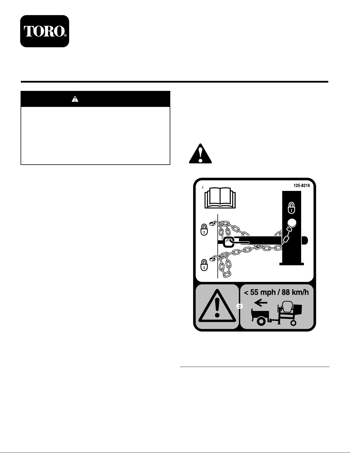
1.ReadtheOperator’s
Manualforinformationon
howtotowthemachine.
OriginalInstructions(EN)
AllRightsReserved
125–8216
2.Warning—limittowing
speedtolessthan55mph
/88km/h.
PrintedintheUSA
*3379-218*A
Page 2
Installation
G021091
1
G021092
1
LooseParts
Usethechartbelowtoverifythatallpartshavebeenshipped.
ProcedureDescription
1
2
3
1
Partsneededforthisprocedure:
1Towpole
1
Frontstabilizerleg(shippedwiththemachine)
6
Shortbolt
1Longbolt
7
Locknut
Towpole1
Frontstabilizerleg(shippedwiththe
machine)
Shortbolt
Longbolt1
Locknut
Hitchassembly1
Flange-headbolt2
Locknut2
Safetychain
Connectinglink
1.Supportpoints
Qty.
Use
1
6
7
1
2
Installthetowpole.
Installthehitchassembly.
Installthesafetychainandconnecting
links.
Figure1
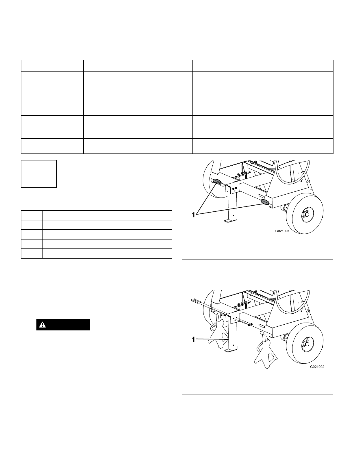
3.Removethe2nutsandboltsthatsecurethefront
Procedure
1.Lowertherearstabilizerlegs;refertothemachine
Operator’sManual.
2.Placejackstandsunderthefrontframerailtoprevent
themachinefromtippingforward(
Figure1).
stabilizerlegtotheframe(
frontstabilizerleg.
Figure2),andremovethe
WARNING
Mechanicalorhydraulicjacksmayfailto
supportthemachineandcauseseriousinjury.
Usejackstandswhensupportingthemachine.
Figure2
1.Frontstabilizerleg
4.Installthetowpoleintotheopeningatthefrontofthe
machine,andsecureitwith6shortboltsand6locknuts
torquedto102N-m(75ft-lb);referto
Figure3.
2
Page 3

G023350
2
3
1
4
G023351
2
2
4
3
1
G023352
InstallingtheHitchAssembly
Partsneededforthisprocedure:
1Hitchassembly
2Flange-headbolt
2Locknut
Figure3
5.Alignthetoprearholeinthefrontstabilizerleg(Figure
4)totherearmostholenearthehandleatthefront
ofthetowpole.
Procedure
1.Using2ange-headboltsand2locknuts,loosely
installthehitchassemblyinthemiddlepositionofthe
mountingplate.
Figure5
Ballhitchshown
1.Locknut(2)3.Flange-headbolt(2)
2.Mountingplate4.Hitchassembly
2.Positionthemachinesothatthetowpoleislevel.
Figure4
1.Locknut
2.Longbolt4.Frontstabilizerleg
6.Installthelongboltthroughtheholes,andsecureit
withalocknuttorquedto102N-m(75ft-lb);referto
Figure4.
Note:Thestabilizerlegpivotsrearwardonthebolt.
Ifyouinstalltheboltintothewronghole,thestabilizer
legwillnotworkproperly.
3.Clevispin
3.Checktherelationshipbetweenthehitchofthe
machineandthehitchofthetowvehicle,andmount
thehitchassemblyin1ofthefollowingpositions:
•Ifthehitchesareapproximatelythesameheight,
keepthehitchassemblyinthemiddlepositionof
themountingplate;refertoFigure6.
•Ifthehitchofthetowvehicleishigh,mountthe
hitchassemblyinthetopposition.
•Ifthehitchofthetowvehicleislow ,mountthe
hitchassemblyinthebottomposition.
7.Inserttheclevispin(Figure4)tolockthefront
Note:Rotatethestabilizerlegupfortowingthemachine,
anddownwhenthemachineisstationary.Alwaysinsertthe
clevispinthroughtheappropriateholestoensurethatthe
stabilizerlegdoesnotmoveunexpectedly.
stabilizerleginposition.
3
Page 4

1
2
3
G023353
Figure6
A B
C D
G023355
2
3
4
3
1
Ballhitchshown
1.Topposition3.Bottomposition
2.Middleposition
Figure7
1.Keyhole
2.Rodorwire(notincluded)4.Connectinglink
3.Safetychain
4.Torquethe2nutsand2boltsto102N-m(75ft-lb).
Important:Refertothemachine
informationabouthitchingandtowingthemachine.
3
InstallingtheSafetyChainand ConnectingLinks
Partsneededforthisprocedure:
1
Safetychain
2
Connectinglink
InstallingtheSafetyChain
1.Formahookontheendofabendablepieceofrod
orstiffwire(notincluded),andinsertitthroughboth
keyholesinthetowpoleofthemachine(Figure7).
Operator’ s Man ual
2.Attachthesafetychaintothelengthofrodorwire
(Figure7).
for
3.Pulltherod,orwire,andthesafetychainthroughboth
keyholes(Figure7).
Note:Ensurethatapproximatelyequallengthsof
safetychainextendfromeithersideofthetowpole.
4
 Loading...