

Page 1
FormNo.3377-532RevB
GrateKit
6cu.ft.and8cu.ft.MortarMixers
ModelNo.68080C—SerialNo.313000001andUp
ModelNo.68081C—SerialNo.313000001andUp
InstallationInstructions
Safety
SafetyandInstructional
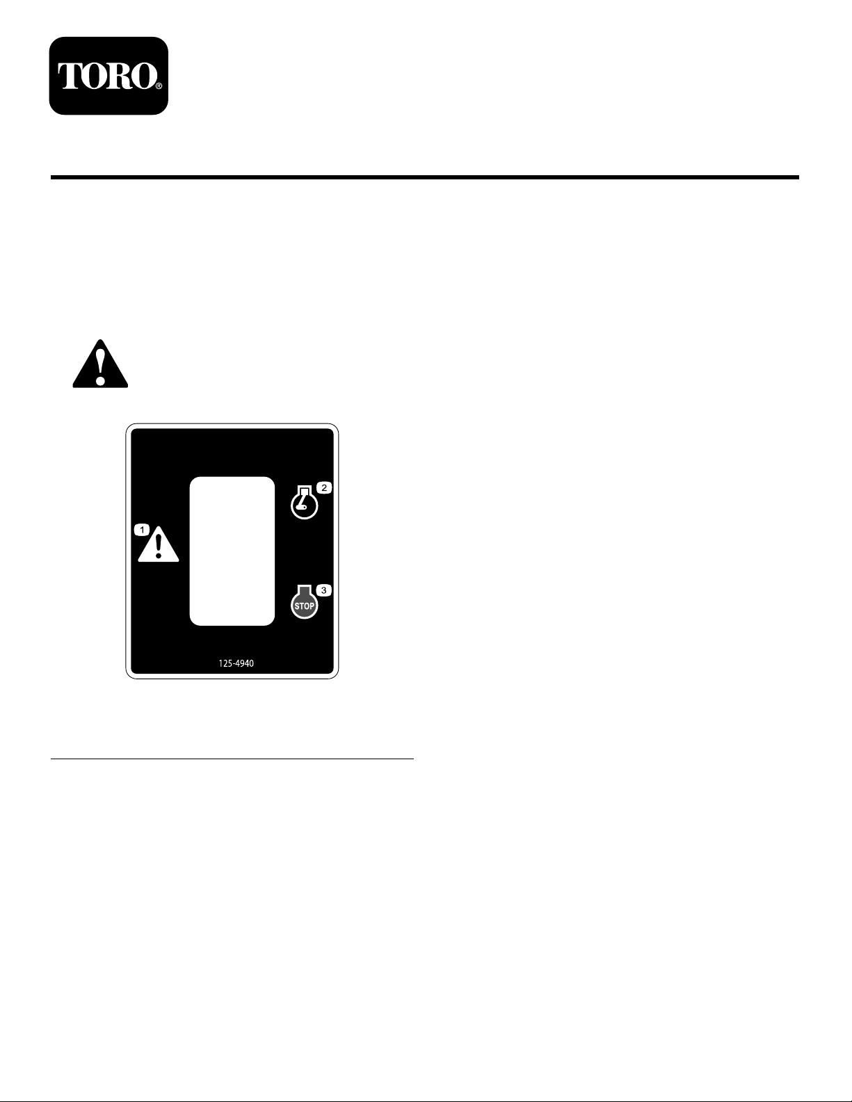
Decals
Safetydecalsandinstructionsareeasilyvisibletotheoperatorandarelocatednearanyareaofpotential
danger.Replaceanydecalthatisdamagedorlost.
1.Warning3.Engine—stop
2.Engine—run
©2013—TheToro®Company
8111LyndaleAvenueSouth
Bloomington,MN55420
125–4940
Registeratwww.T oro.com.
OriginalInstructions(EN)
PrintedintheUSA
AllRightsReserved
*3377-532*B
Page 2

Installation
1
2
3
G021 168
LooseParts
Usethechartbelowtoverifythatallpartshavebeenshipped.
ProcedureDescription
1
2
3
Nopartsrequired
Stationaryguard
Movableguard1
Liftarm
Dumphandle1
Longbolt4
Shoulderbolt
Nut6
Switch
Switchhousing
Wireharness1
Shortbolt
Nut2
Decal1
1
RemovingtheLiftArm,Grate,
Qty.
Use
–
1
1
2
1
1
2
Removethegrateanddumphandle.
Installthegrateanddumphandle.
Installtheswitch.
andDumpHandle
NoPartsRequired
Procedure
1.Removethe2shoulderbolts,2nuts,andfenderwasher
thatsecuretheliftarmtothefrontpostandthegrate
(Figure1).Discardtheliftarm.
Note:Savethehardwareforinstallingthenewliftarm.
Figure1
1.Dumphandle
2.Frontpost
2.Removethe2shoulderboltsandnutsthatsecurethe
gratetothepivotholesontheleftsideofthedrum
(Figure1).
3.Carefullyliftthegrateoffthemachine,anddiscardit.
4.Removethe2nutsandboltsthatsecurethedump
handletothedrum,andremovethedumphandlefrom
themachine(Figure1).
3.Liftarm
2
Page 3

2
G0 2118 6
1
2
1
2
3
4
5
6
7
9
4
10
5
4
G021 169
8
InstallingtheLiftArm,Grate,
andDumpHandle
Partsneededforthisprocedure:
1
Stationaryguard
1Movableguard
1
Liftarm
1Dumphandle
4Longbolt
2
Shoulderbolt
6Nut
Procedure
1.Placethestationaryguardontopofthedrum,sothat
thepivotholesareontherightside,nearthechute
(Figure2).
Figure2
1.Pivotholes
2.Chute
1.Longbolt
2.Stationaryguard7.Shoulderbolts(existing)
3.Dumphandle
4.Nut
5.Shoulderbolt
3.Installthedumphandleontothe2frontbolts,and
securetheguardandthehandlewithnutstorquedto
41N-m(30ft-lb);referto
Note:Ensurethatthestationaryguardislevelwith
theedgesofthedrum.
4.Securethe2boltsattherearoftheguardwithnuts
torquedto41N-m(30ft-lb);refertoFigure3.
5.Aligntheboltholesinthestationaryguardandthe
movableguard,andsecurethemwiththe2shoulder
boltsandnutstorquedto22N-m(16ft-lb);referto
Figure3.
2.Insertthe4longboltsthroughthemountingholesin
thedrumandthestationaryguard,fromtheinsideof
thedrum(Figure3).
6.Aligntheslotintheliftarmwiththeboltholeinthe
frontcornerofthemovableguard,andsecureitwitha
shoulderbolt,fenderwasher,andnut(fromtheoriginal
liftarm)torquedto22N-m(16ft-lb);refertoFigure3.
Figure3
6.Liftarm
8.Fenderwasher(existing)
9.Nuts(existing)
10.Movableguard
Figure3.
7.Alignthebottomholeintheliftarmwiththehole
inthetabonthefrontpost,andsecureitwiththe
othershoulderboltandnut(fromtheoriginalliftarm)
torquedto22N-m(16ft-lb);referto
Figure3.
3
Page 4

3
1
G021 170
2
3
4
5
6
7
2
4
5
6
7
G021 173
3
8
1
InstallingtheEngineSwitch
7.Center-punchthemark,anddrilla10mm(3/8inch)
holethere(Figure4).
InstallingtheSwitch
1.Opentherearcowl.
Partsneededforthisprocedure:
1
Switch
1
Switchhousing
1Wireharness
2
Shortbolt
2Nut
1Decal
DrillingtheHolesintheCowl
1.Ontherightsideoftheforwardcowl,makeamark
15.2cm(6inches)upfromthesidebend,and16.5cm
(6-1/2inches)backfromthefrontedge(Figure4).
2.Removethedividerplate;refertothemachineOperator’ s
Manual.
3.Cliptheswitchintotheswitchhousing(
Ensurethattheroundedendoftheswitchistoward
thestoppositionontheswitchhousing.
Figure5).
Figure5
1.Nuts
Figure4
1.15.2cm(6inches)5.Holeforther-treemount
2.16.5cm(6-1/2inches)6.8.9cm(3-1/2inches)
3.6.4cm(2-1/2inches)7.7.0cm(2-3/4inches)
4.Holesfortheswitch
2.Makeamark6.4cm(2-1/2inches)abovetherst
markandanothermark6.4cm(2-1/2inches)below
therstmark(Figure4).
3.Center-puncheachmarktoensurethatthedrillbit
doesnottraveloffofeachmark.
4.Drilla51mm(2inch)holeonthecentermark(
4).
5.Drilla10mm(3/8inch)holeonthetopmark,and
another10mm(3/8inch)holeonthebottommark
(
Figure4).
6.Ontherightsideoftheforwardcowl,makeamark8.9
cm(3-1/2inches)belowthebendand7.0cm(2-3/4
inches)infrontofthebackedge(Figure4).
Figure
2.Grommet6.Switchhousing
3.Decal7.Wireharness
4.Switch
4.Installthegrommetintothecenterhole(Figure5).
5.Routethewireharnessthroughthecenterholewith
thegrommet,andplugitintotheswitch(Figure5).
6.Installtheswitchhousingontotheforwardcowlwith
the2shortboltsandnutstorquedto22N-m(16ft-lb);
refertoFigure5.
Note:Positiontheswitchandhousingsothatthe
stopposition(andtheroundedendoftheswitch)is
atthebottom.
5.Shortbolt(2)
8.Fir-treemount
4
Page 5

ConnectingtheWires
G021 171
2
3
4
1
1
2
G021 167
3
4
G021 172
2
345
1
1.Opentheengine-mountedcliptoaccessthewires
(Figure6).
Note:Youmayneedtouseascrewdriveroranother
tooltoprytheclipopen.
Figure8
Figure6
1.Engine-mountedclip3.Blackwire
2.Yellowwire4.Redwire
2.Disconnecttheblackwireontheengine-mounted
switchfromtheblackwireontheengine(Figure6).
3.Connectthegraywireonthecowl-mountedswitch
totheblackwireontheengine-mountedswitch
(Figure7andFigure8).
1.Engine-mountedclip
2.Blackwire(engine)
3.Blackwire(cowl-mounted
switch)
4.Graywire(cowl-mounted
switch)
5.Blackwire
(engine-mountedswitch)
4.Connecttheblackwireonthecowl-mountedswitchto
theblackwireontheengine(Figure7andFigure8).
Note:Donotdisconnecttheredwireortheyellow
wire.
5.Bundleandsecurethewireswiththeengine-mounted
clip.
6.Installther-treeclipintothe10mm(3/8inch)hole
thatyoudrilledintheforwardcowlinstep
6ofDrilling
theHolesintheCowl(page4).
7.Installthedividerplate;refertothemachineOperator’ s
Manual.
Note:Ensurethatthedividerplatedoesnotstretch
orpinchthewireharness.
TestingtheSwitches
Fortheenginetostartandrun,theengine-mountedswitch
mustbeintheOnposition,andthecowl-mountedswitch
mustbeintheRunposition.
1.Blackwire
(engine-mountedswitch)
2.Graywire(cowl-mounted
switch)
Figure7
3.Blackwire(cowl-mounted
switch)
4.Blackwire(engine)
1.Switchtheengine-mountedswitchtotheOnposition
andthecowl-mountedswitchtotheRunposition.
2.Starttheengine;refertothemachineOperator’sManual.
3.Whiletheengineisrunning,movethecowl-mounted
switchtotheStopposition.Theengineshouldstop.
4.Repeatsteps1and2,andmovetheengine-mounted
switchtotheOffposition.Theengineshouldstop.
Note:Ifthereisanyproblemwiththeenginestartingor
stopping,ensurethatthewiresareconnectedasdescribedin
ConnectingtheWires(page5).
5
Page 6

Notes:
6
Page 7

Notes:
7
Page 8

 Loading...