

Page 1
ControlCoverKit
TR-34DTrenchRoller
ModelNo.68070
WARNING
CALIFORNIA
Proposition65Warning
Thisproductcontainsachemicalorchemicals
knowntotheStateofCaliforniatocausecancer,
birthdefects,orreproductiveharm.
LooseParts
Usethechartbelowtoverifythatallpartshavebeenshipped.
FormNo.3377-640RevB
InstallationInstructions
Description
Nopartsrequired
Nopartsrequired
Cover
Latchclip1
Latchmountassembly1
Catchmountassembly
Washer(5/16inch)
Hex-socketbolt(1/4x5/8inches)
Hex-socketbolt(1/4x1-1/4inches)
Flangenut(1/4inch)
DisconnectingtheBattery
1.Opentherearhood;refertotheOpeningtheHood
sectionintheOwner’sManual
2.Loosenthenutandboltsecuringthenegative-cable
clamptothebatterypost,andremovetheclampfrom
thebattery.
Note:Ensurethatthenegative-cableclampdoesnot
contactthebatterypost.
Qty.
13
15
Use
–
–
1
1
2
2
Disconnectthebattery.
Drilltheholes(machineswithoutexistingholes).
Installthecontrolcover.
DrillingtheHoles(Machines
withoutExistingHoles)
1.Covertherearcompartmentofthemachinewith
adropclothtoprotectthecomponentsinthe
compartmentfrommetalshavingsthatwillbecreated
whiledrillingmountingholesforthecontrolcover.
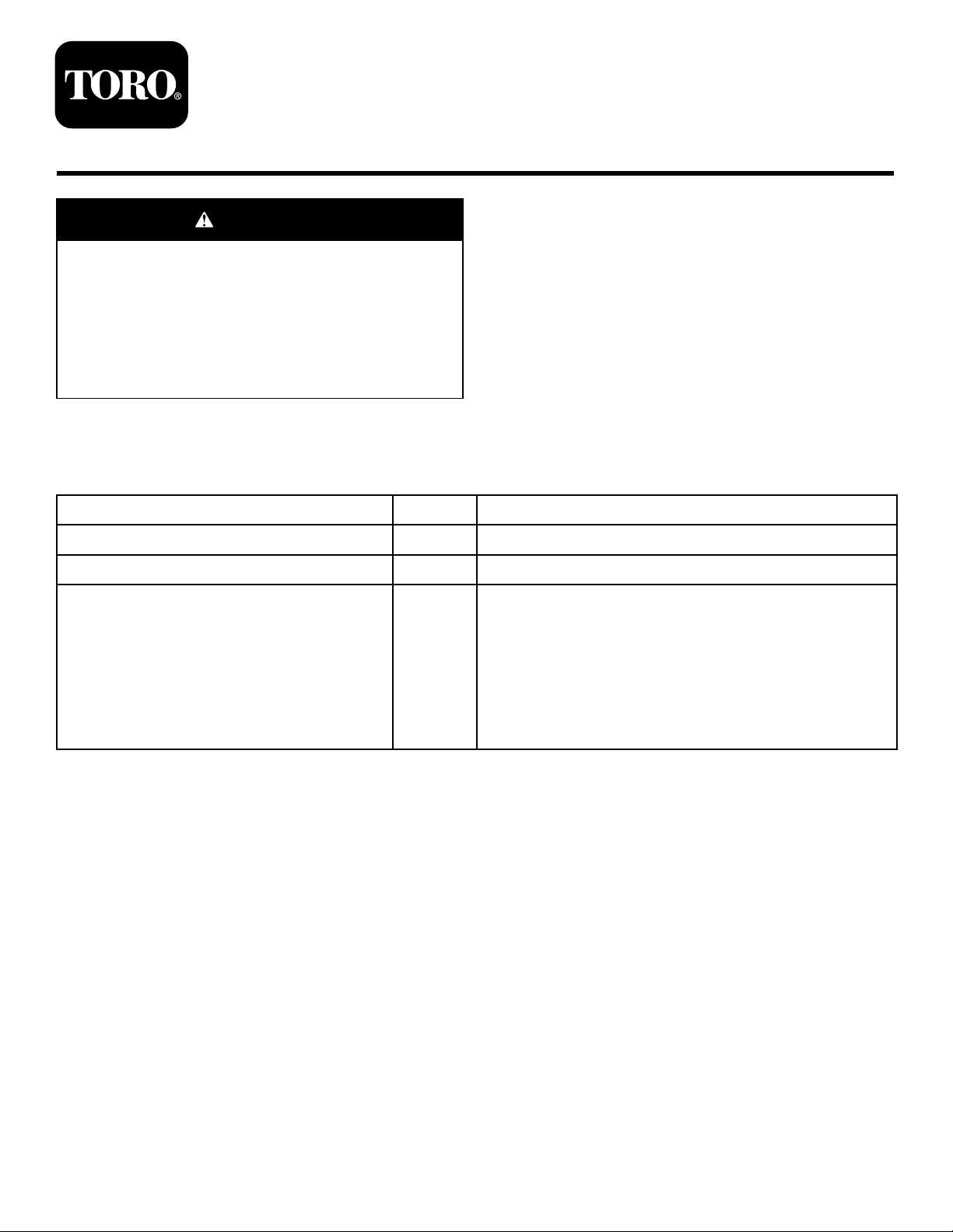
2.Alignthecoverlefttorightoverthecontrolpanel
(
Figure1).
©2013—TheT oro®Company
8111LyndaleAvenueSouth
Bloomington,MN55420
Registeratwww.T oro.com.
3.Whilekeepingthehoodcentered,alignthebottom
edgeofthecovertotherearedgeofthehood(Figure
1).
OriginalInstructions(EN)
PrintedintheUSA.
AllRightsReserved
*3377-640*B
Page 2
G021638
1
2
3
4
5
6
Figure1
g021622
2
1
1
1.Rearedgeofthehood4.Cover
2.Bottomedgeofthecover
3.Hingedcover6.Alignthecovertotheedge
5.Holesincover
ofthehood
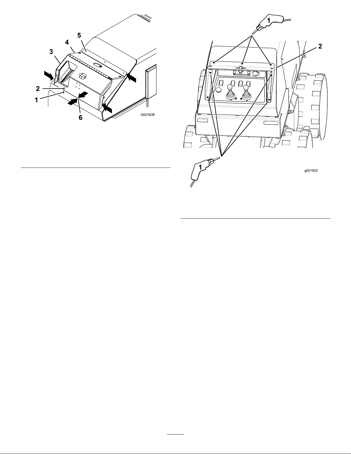
4.Usingthecoverasatemplate,marktheoutlineofthe
holesontherearhood(Figure2).
5.Removethecoverfromthemachine.
6.Center-punchthehoodatthemarkedlocationscreated
instep4.
7.Drill7holesintotherearhoodwitha9/32inchdrill
bitatthecenter-punchmarks(Figure2).
Figure2
1.Markanddrill9/32inch
holeshere
2.Usethecoverasa
template
8.Removethedropclothundertherearhoodand
components.
2
Page 3

InstallingtheControlCover
g021624
1
2
g024194
3
2
4
1
1
2
3
4
g024193
1
2
3
g024192
1.Installthecovertotherearhoodwith7hex-socket
bolt(1/4x5/8inches)and7angenuts(1/4inch)
(Figure3).
Note:Applyathread-lockingcompound.
3.Assemblethelatchcliptothelatchmountwith2
hex-socketbolts(1/4x1-1/4inches),2washers(5/16
inch),and2angenuts(1/4inch)(Figure5).
Note:Applyathread-lockingcompound.
Figure5
Figure3
1.Hex-socketbolt(1/4x5/8
inches)
2.Flangenuts(1/4inch)
2.Installthelatchmountassemblytothemachinewith2
hex-socketbolts(1/4x5/8inches)and2angenuts
(1/4inch)(
Figure4).
Note:Removeanystickersblockingtheholes.
Note:Applyathread-lockingcompound.
1.Hex-socketbolt(1/4x
1-1/4inches)
2.Washer
3.Latchclip
4.Flangenuts(1/4inch)
4.Installthecatchmountassemblytothemachinewith4
hex-socketbolts(1/4x5/8inches)and4angenuts
(1/4inch)(Figure6).
1.Cutslotsoutindecal3.Hex-socketbolt(1/4x5/8
2.Latchmountassembly
Figure4
4.Flangenuts(1/4inch)
1.Flangenuts(1/4inch)3.Hex-socketbolt(1/4x5/8
2.Catchmountassembly
Figure6
inches)
5.Connectthenegativebatterycabletothebattery.
inches)
3
Page 4

 Loading...