

Page 1

TrailerLightKit
End-DumpMixers
ModelNo.68063
Installation
LooseParts
Usethechartbelowtoverifythatallpartshavebeenshipped.
FormNo.3377-604RevB
InstallationInstructions
ProcedureDescription
1
2
3
4
Leftbracket
Rightbracket1
Bolt4
Nut4
Wireharness1
Cableclamp
Shortbolt
Nut
Largegrommet2
Smallgrommet
Cabletie
Leftlight
Rightlight1
Centerlight
Center-lightharness
License-plateholder1
Longbolt2
Nut6
Cabletie
Reector
Shortbolt
Nut2
Qty.
Use
1
Installthebrackets.
8
5
5
1
4
1
1
1
1
2
2
Installthewires.
Installthelights.
Installthereectors.
5
©2013—TheToro®Company
8111LyndaleAvenueSouth
Bloomington,MN55420
Nopartsrequired
Registeratwww.T oro.com.
–
Replacethelightbulbs.
OriginalInstructions(EN)
PrintedintheUSA
AllRightsReserved
*3377-604*B
Page 2
1
1
G021010
1
1
2
G021012
2
InstallingtheBrackets
Partsneededforthisprocedure:
1
Leftbracket
1Rightbracket
4Bolt
4Nut
Procedure
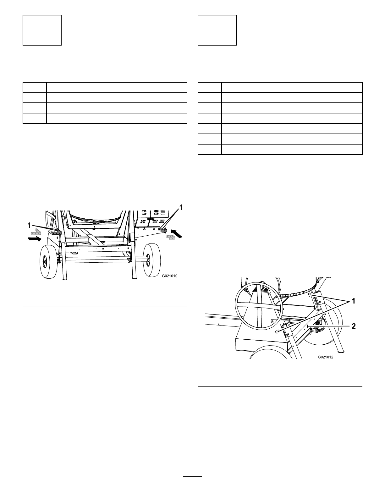
1.Aligntheboltholesontheendofthelongsideofthe
leftbracket(L-shaped)withtheboltholesintheleft
sideoftheframe,nearthehandwheel(Figure1).
Note:Foroldermodels,drill2holes(7.5mmor9/32
inch)intheframe,spaced51mm(2inches)apart,to
accommodatethe2mountingboltsforthebracket.
InstallingtheWires
Partsneededforthisprocedure:
1Wireharness
8
Cableclamp
5
Shortbolt
5
Nut
2Largegrommet
1
Smallgrommet
4
Cabletie
Procedure
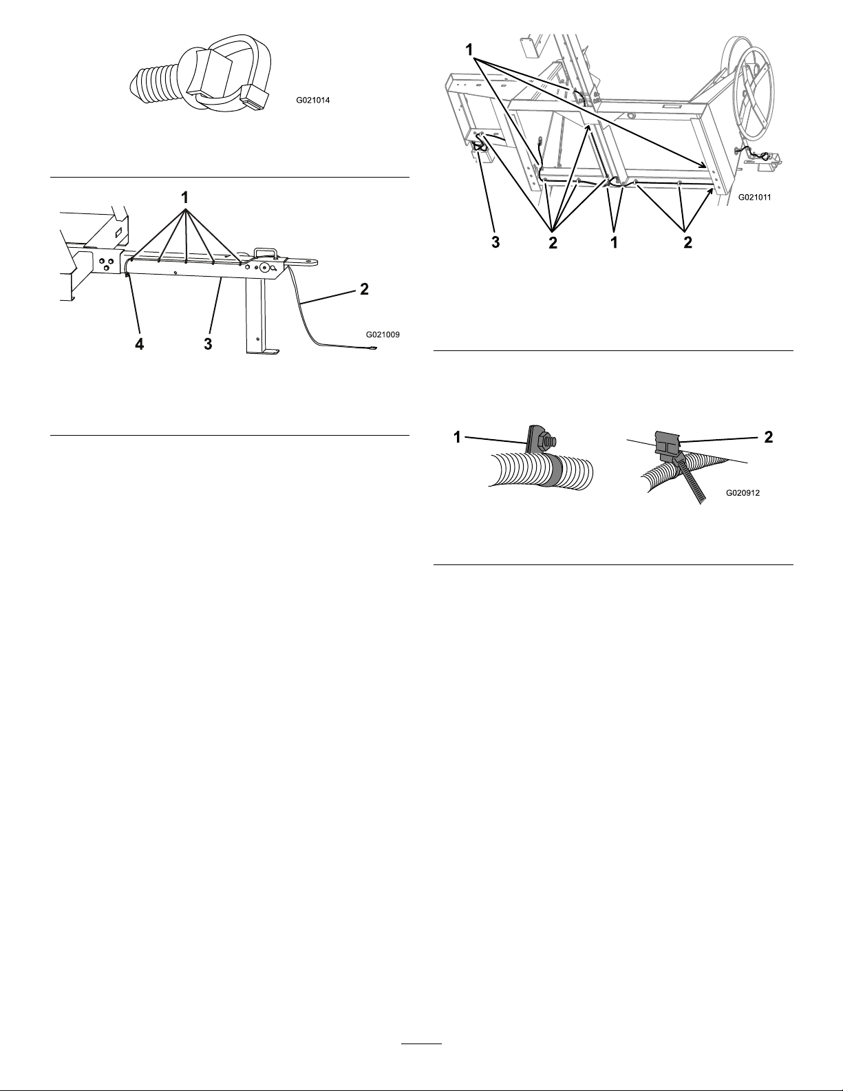
Note:Throughoutthewireinstallation,makesurethatthe
wiresaresecurebutnotpulledtight.Usethecabletiesas
neededtosecuretowires,andkeep1cabletieforInstalling
theCenterLight(page5).
1.Installthelargegrommetsintotheholesinthesides
oftheframeandthesmallgrommetintotheholein
therearoftheframe,alignedwiththecenterframe
rail(Figure2).
Figure1
1.Boltholes
2.Insertaboltthrougheachofthe2holesinthebracket
andtheframe,andsecureeachboltwithanut.
3.Aligntheboltholeson1endoftherightbracket
(U-shaped)withtheboltholesintheengine-deck
support.
Note:Foroldermodels,drill2holes(7.5mmor9/32
inch)intheengine-decksupport,spaced51mm(2
inches)apart,toaccommodatethe2mountingbolts
forthebracket.
4.Insertaboltthrougheachofthe2holesinthebracket
andtheengine-decksupport,andsecureeachboltwith
anut.
Note:Foroldermodels,drilla41mm(1-5/8inch)
holeineachsideoftheframe,anda22mm(7/8inch)
holeintherearoftheframe.
Figure2
1.Largegrommetholes
2.Ensurethatthetongueisattachedtothemachine,and
pushthe5pre-installedpushmounts(Figure3)atthe
frontofthewireharnessintothe5holesintheright
sideofthetongue(Figure4).
2.Smallgrommethole
2
Page 3
G021014
Figure3
1
3
4
2
G021009
G02101 1
1
2
2
1
3
G020912
21
Pushmount
Figure5
Frameundersideshownforclarity
1.Edgeclips3.Wireharness
2.Cableclamps
Figure4
1.Pushmounts3.Tongue
2.Wireharness4.Edgeclip
3.Routethefrontofthewireharnessthroughthetongue
handle(Figure4).
Note:Foroldermodels,drill5holes(6.75mmor
17/64inch),spaced15.2cm(6inches)apart,alongthe
rightsideofthetongue.
4.Securethenearestedgecliptothebottomedgeofthe
tongue,androutethewireharnessupintotheinside
ofthecenteroftheframe,towardthebackofthe
machine(Figure4).
5.RoutethewireharnessasshowninFigure5.
Note:Ensurethateachsideofthewireharnessgoes
tothecorrectsideofthemachine.Ifyouswitchthe
wiringofthelights,eachturnsignalwillashonthe
wrongside.Thesidewiththegreenwireisforthe
rightside,andthesidewiththeyellowwireisforthe
leftside.
6.Usecableclampsandthepre-installededgeclipsto
securethewireharnessalongtheinsideoftheframe
(Figure6).
Figure6
1.Cableclamp
2.Edgeclip
Note:Install2ofthecableclampslater,whenyou
installthecenterlight.
Touseacableclamp,spreaditapartandtthewire
harnessintoit.Thensqueezetheclampbacktogether.
Fastentheclamptotheframeofthemachinewitha
nutandabolt,usingthepre-drilledholesalongthe
frame.Tightenthenutsandboltsuntiltheyaresecure.
Foroldermodels,drilla7.5mm(9/32inch)holefor
eachbolt.
Touseapre-installededgeclip,pushitintoposition
alongtheedgeoftheframe(Figure6).
7.Pushthe2pre-installedpushmountsneartheyellow
wireintothe2cornerholesintheleftlightbracket,
sothatthewiresarepointingawayfromthemachine
(
Figure7).
3
Page 4

G021023
1
Figure7
G021026
1
1
G021013
G021016
1
2
3
4
5
1.Pushmounts
8.Pushthepre-installedpushmountnearthegreenwire
intotheopenholeclosesttothebolts,intheright
lightbracket(Figure8).
3
InstallingtheLights
Partsneededforthisprocedure:
1
Leftlight
1Rightlight
1
Centerlight
1
Center-lightharness
1License-plateholder
2Longbolt
6Nut
1
Cabletie
InstallingtheSideLights
1.Positionthelicense-plateholderontothepostsofthe
lightwiththeclearbottomlenssothattheclearlensis
facingthelicense-plateholder(Figure10).
Figure8
1.Pushmount
9.Tosecurethecableclampneartherightlightbracket,
useaboltthatsecuresthebracket(Figure9).
Figure9
1.Nutandbolt
Figure10
Leftlight
1.Yellowwire—stopandturn4.License-plateholder
2.Brownwire—taillight
3.Whitewire—ground
5.Clearlens
Note:Thisistheleftlight,whichilluminatesthe
licenseplatethroughtheclearlens.
2.Installthelightsothatthepostsgointotheholesin
thebracketontheleftsideofthemachine(Figure10).
3.Installtheroundterminalofthegroundwire(white)
ontotheoutsidethreadedpost(Figure10).
4.Installthenutsontothethreadedposts;tightenthem
byhandtopreventcross-threading,thenuseawrench
tosecurethemuntiltheyaresnug.
Important:Donotovertightenthenuts,orthe
plastichousingwillbreak.
4
Page 5

5.Pushthewiresintotheappropriateholesinthelight
1
2
3
G021017
G021024
1
2
3
G021018
G021015
1
G021025
1
2
3
4
(Figure10).
Note:Ifyouneedtoremoveawirefromthelight,
inserttheendofapaperclipintothesmallholeunder
thewire,thenpullthewireout.
6.Repeatsteps3through6forthelightontherightside
ofthemachine.
Figure13
Figure11
Rightlight
1.Brownwire—taillight3.Whitewire—ground
2.Greenwire—stopandturn
InstallingtheCenterLight
1.Installtheconnectorsofthecenter-lightharnessonto
thebackofthecenterlightasshowninFigure12.
1.Boltholes
2.Centerlight
3.Grommethole
Note:Usethenutsandlongboltsthatsecurethe
centerlighttoalsosecure2cableclamps(Figure14);
usethesetohelpsecurethemainwireharness.You
installedthesecableclampsinstep6ofprocedure2
InstallingtheWires(page2).
Figure14
1.Nutsandbolts
3.Connectthewiresofthecenterlightwiththemain
wireharnessasshownin
Figure12
2.Routetheendsofthewiresofthecenterlightthrough
theholeintherearoftheframe,andsecurethecenter
lightwithanutandalongboltoneachsideofthe
light(
Figure13).
Note:Foroldermodels,drill2holes(7.5mmor9/32
inch)intheframe,spaced40.8cm(16-1/16inches)
apart,toaccommodatethe2mountingboltsforthe
1.Blackwire—taillight3.Whitewire—ground
2.Brownwire—taillight4.Whitewire—ground
Note:Usethecabletietosecureanyexcesswirenear
thecenterlight.
Figure15.
Figure15
centerlight.
5
Page 6

4
G021008
1
2
A
B
C
E
F
G020829
5
InstallingtheReectors
Partsneededforthisprocedure:
2
Reector
2
Shortbolt
2Nut
Procedure
1.Aligntheholeinareectortotheholein1sideofthe
tongueofthemachine(
Note:Foroldermodels,drilla7.5mm(9/32inch)
holeforeachbolt,centeredbetweenthesafety-chain
keyholeandtheclevis-pinhole.
Figure16).
ReplacingtheLightBulbs
NoPartsRequired
ReplacingtheRear-facingSideBulbs
Note:Theleftrear-facingbulbalsoilluminateslicenseplate.
1.Useascrewdrivertoremovethe4screwsfromthe
largesquarelensonthelight(Figure17).
Figure16
1.Reector
2.Insertaboltthroughtheholeinthereectorandthe
tongue,andinstallanutontheotherside.
3.Useawrenchontheboltandanotherwrenchonthe
nuttotightenthemuntiltheyaresnug.
Important:Donotovertightenthenutsandbolts,
ortheplasticreectorswillbreak.
4.Repeatsteps1through3fortheothersideofthe
tongue.
2.Tongue
Figure17
2.Removethelens(Figure17).
3.Pushandtwistthebulbcounterclockwisetoremoveit
fromthesocket(Figure17).
4.Pushanew1157bulbintothesocketandthentwistit
clockwise(Figure17).
5.Installthelensandthe4screws(
Figure17).
ReplacingtheSide-facingBulbs
1.Useascrewdrivertoremovethe2screwsfromthe
smallrectangularlensonthesideofthelight(Figure
18).
6
Page 7

A
B
C
E
F
G020830
Figure18
A
B
C
G021019
A
B
C
G021021
2.Removethelens(Figure18).
3.Pullthebulboutofthesocket(Figure18).
4.Pushanew168bulbintothesocket(Figure18).
5.Installthelensandthe2screws(Figure18).
ReplacingtheCenterBulbs
Note:Eachcenterbulbisintegratedintothelens.
1.Push1ofthetabsoverthatholdsthelensassembly
inplace,andpullthelensawayfromtherestofthe
center-lightassembly(Figure19).
Figure19
2.Disconnectthewireconnectorfromthelensassembly .
3.Connectthewireconnectortoanewlensassembly,
andinstallthelensassemblyontotherestofthe
center-lightassembly(Figure20).
Figure20
7
Page 8

 Loading...