

Page 1
TrailerLightKit
Side-DumpMixers
ModelNo.68062
WARNING
CALIFORNIA
Proposition65Warning
Thisproductcontainsachemicalorchemicals
knowntotheStateofCaliforniatocausecancer,
birthdefects,orreproductiveharm.
Installation
FormNo.3377-600RevB
InstallationInstructions
LooseParts
Usethechartbelowtoverifythatallpartshavebeenshipped.
ProcedureDescription
Bracket2
1
2
3
4
Bolt4
Nut4
Wireharness1
Cableclamp
Edgeclip—parallel4
Edgeclip—perpendicular1
Fir-treemount2
Bolt
Nut
Cabletie
Grommet
Light2
License-plateholder1
Nut4
Reector
Bolt2
Nut2
Qty.
Use
Installthebrackets.
7
Installthewires.
5
5
5
2
Installthelights.
2
Installthereectors.
5
©2013—TheT oro®Company
8111LyndaleAvenueSouth
Bloomington,MN55420
Nopartsrequired
Registeratwww.T oro.com.
–
Replacethelightbulbs.
OriginalInstructions(EN)
PrintedintheUSA
AllRightsReserved
*3377-600*B
Page 2
1
1
G020909
G021014
G020910
1
2
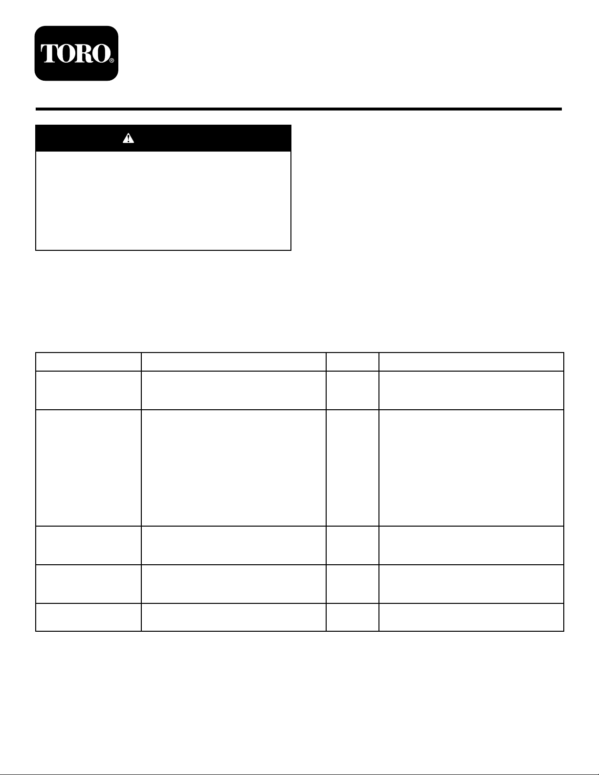
InstallingtheBrackets
Partsneededforthisprocedure:
2Bracket
4Bolt
4Nut
Procedure
1.Aligntheboltholesofabracketwiththeboltholesin
thesideframerailunderthecowl(Figure1).
Note:Foroldermodels,drill(2)7.5mm(9/32inch)
holesoneachsideoftheframe,spaced5.1cm(2
inches)apart,toaccommodatethe2mountingbolts
foreachbracket.
InstallingtheWires
Partsneededforthisprocedure:
1Wireharness
7
Cableclamp
4Edgeclip—parallel
1Edgeclip—perpendicular
2Fir-treemount
5
Bolt
5
Nut
5
Cabletie
2
Grommet
Procedure
Differentmodelsuseadifferentnumberoffasteners.Usethe
appropriatenumberoffastenersforyourmachine.
1.Pushthepre-installedr-treemount(
shortbranch(withtheyellowwire)ofthewireharness
intotheholeclosesttothemachine,intheleftlight
bracket(Figure3).
Figure2)onthe
Figure2
Figure1
1.Boltholes
2.Insertaboltthrougheachofthe2holesinthebracket
andtheframe.
3.Installanutoneachbolt.
Note:Tightenthesenutsandboltslater,when
youmountthecableclamps;refertostep4in
2InstallingtheWires(page2).
4.Repeatsteps1through3ontheothersideofthe
machine.
1.Fir-treemount
Note:Ensurethateachsideofthewireharnessgoes
tothecorrectsideofthemachine.Ifyouswitchthe
wiringofthelights,eachturnsignalwillashonthe
wrongside.
2.Pushthepre-installedr-treemountonthelong
branch(withthegreenwire)ofthewireharnessinto
theholeclosesttothemachine,intherightlight
bracket(
Figure3).
Figure3
2
Page 3
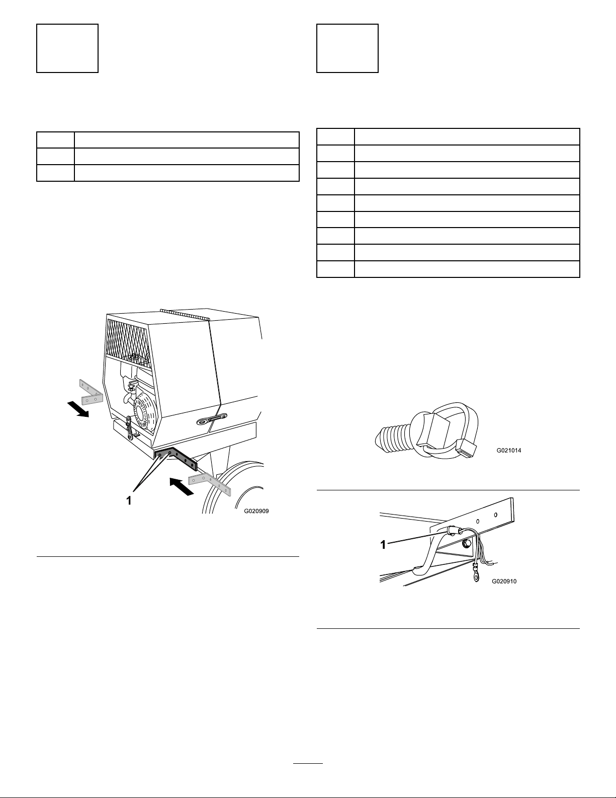
3.RoutethewireharnessasshowninFigure4,Figure7,
1
2
4
4
3
4
G021626
2
1
2
G021629
orFigure8,dependingonthemodel.
Figure4
Concretemixers(frameundersideshownforclarity)
1.Edgeclip3.Wireharness
2.Excesswire
4.Cableclamp
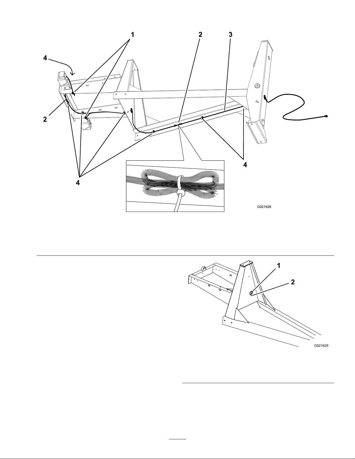
Note:Someconcretemixers(Figure4)haveaholein
therearverticalpartoftheframe;installagrommetin
thehole,routethewireharnessthroughthegrommet,
andsecurethewireharnessbypushingar-treemount
intothesmallholeunderthegrommet(Figure5).If
yourmachinedoesnothaveahole,routethewire
harnessundertheframe,andsecureitwithanedge
clip(Figure6).
Figure5
Framewithhole
1.Holeandgrommet
2.Holeforr-treemount
3
Page 4

1
G021630
1.Edgecliplocation
1
4
2
4
3
G021627
2
Figure6
Framewithouthole
Figure7
Belt-drivemortarmixers(frameundersideshownforclarity)
1.Edgeclip3.Wireharness
2.Excesswire
4.Cableclamp
4
Page 5

1
2
3
4
4
G021628
Figure8
G020912
21
G020980
1
Gear-boxmortarmixer(frameundersideshownforclarity)
1.Edgeclip3.Wireharness
2.Excesswire
4.Usecableclampsandedgeclipstosecurethewire
harnessalongtheinsideoftheframe(Figure9).
4.Cableclamp
Figure9
1.Cableclamp
2.Edgeclip
Note:Touseacableclamp,spreaditapartandt
thewireharnessintoit.Thensqueezetheclampback
together.Fastentheclamptotheframeofthemachine
withanutandabolt,usingthepre-drilledholesalong
theframe.Tightenthenutsandboltsuntiltheyare
secure.
Foroldermodels,drilla7.5mm(9/32inch)holefor
eachbolt.
Ineachofthe2rearcornersoftheframe,useanut
andboltthatsecurethelightbrackettoalsosecurea
cableclamp(Figure10).
Note:Ensurethatyoutightenthe2nutsandbolts
1.Nutandbolt
Note:Touseanedgeclip,pushitintopositionalong
theedgeoftheframeandinsertacabletiethroughthe
slot.Usethecabletietosecurethewireharness.
5.Pullthefrontendofthewireharnessoutthroughthe
holeinthefrontpostofthemachinesothatthereis
about61cm(24inches)ofslackbeyondthefrontof
theinstalledtowpole(Figure11).
Note:Foroldermodels,useaholesawtodrilla4.2
cm(1-5/8inch)holeinthefrontpostofthemachine,
sothatthewireharnessexitstheframeinlinewith
thehorizontalframerails.
Figure10
foreachbracket.
5
Page 6

1
2
3
G02091 1
Figure11
G020981
G020913
1
2
3
4
5
3
InstallingtheLights
Partsneededforthisprocedure:
2Light
1License-plateholder
4Nut
1.Grommet3.Cabletie
2.Fir-treemount
6.Slidethegrommetoverthe4-pinconnector(Figure12)
onthefrontofthewireharness,andinstallitinthe
holeinthefrontpost(Figure11).
Figure12
7.Pushther-treemountintothesmallholenextto
wherethewireentersthefrontpost,andinsertacable
tiethroughtheslot.
Note:Usethecabletietosecurethewireharness.
Foroldermodels,drilla7mm(17/64inch)holefor
ther-treemount.
8.Stowtheexcesswireasfollows:
•Forconcretemixers,stowtheexcesswireonthe
undersideoftheleftframerail.Usecabletiesto
securetheexcesswiretothepreviouslyinstalled
sectionofwire.
•Formortarmixers,coiltheexcesswireandbundle
itwithacabletie.Stowthebundledexcesswire
insidethecenterframerail,andsecurethebundle
withanothercabletieasnearaspossibletothe
edgeclip.
•Ifthereisexcesswirebetweentheleftlightand
therightlight,bundleitwithacabletie,andsecure
ittoapreviouslyinstalledsectionofwirewith
anothercabletie.
Important:Ensurethatanyexcesslengthinthe
wireharnessissecurewithcabletiesandwillnot
comeloose.
Procedure
1.Positionthelicense-plateholderontothepostsofthe
lightwiththeclearbottomlens,sothattheclearlensis
facingthelicense-plateholder(Figure13).
Figure13
Leftlight
1.Yellowwire—stopandturn4.License-plateholder
2.Brownwire—taillight
3.Whitewire—ground
Note:Thisistheleftlight,whichilluminatesthe
licenseplatethroughtheclearlens.
2.Installthelightsothatthepostsgointotheholesin
thebracketontheleftsideofthemachine(Figure13).
3.Installtheroundterminalofthegroundwire(white)
ontotheoutsidethreadedpost(Figure13).
4.Installthenutsontothethreadedposts;tightenthem
byhandtopreventcross-threading,thenuseawrench
tosecurethemuntiltheyaresnug.
Important:Donotovertightenthenuts,orthe
plastichousingwillbreak.
5.Pushthewiresintotheappropriateholesinthelight
Figure13).
(
Note:Ifyouneedtoremoveawirefromthelight,
inserttheendofapaperclipintothesmallholeunder
thewire,thenpullthewireout.
5.Clearlens
6.Repeatsteps2through5forthelightontheright-hand
sideofthemachine(
Figure14).
6
Page 7

G020914
1
2
3
Figure14
1
G020915
1
G020921
Rightlight
1.Greenwire—stopandturn
2.Brownwire—taillight
3.Whitewire—ground
4
InstallingtheReectors
Partsneededforthisprocedure:
2
Reector
2Bolt
2Nut
Procedure
1.Aligntheholeinareectortotheholein1sideofthe
frontpostonthemachine(Figure15).
Note:Foroldermodels,drilla7.5mm(9/32inch)
holeforeachbolt.
Figure16
Model68024
1.Reector
2.Insertaboltthroughthereectorandtheframe,and
installanutontheotherside.
3.Useawrenchontheboltandanotherwrenchonthe
nuttotightenthemuntiltheyaresnug.
Important:Donotovertightenthenutsandbolts,
ortheplasticreectorswillbreak.
4.Repeatsteps1through3fortheotherside.
Figure15
1.Reector
Note:Formodel68024,mountthereectorsonthe
triangularsupports(Figure16).
7
Page 8

5
A
B
C
E
F
G020829
A
B
C
E
F
G020830
ReplacingtheLightBulbs
NoPartsRequired
ReplacingtheRear-facingBulbs
Note:Theleftrear-facingbulbalsoilluminateslicenseplate.
1.Useascrewdrivertoremovethe4screwsfromthe
largesquarelensonthelight(Figure17).
Figure17
2.Removethelens(Figure17).
3.Pushandtwistthebulbcounterclockwisetoremoveit
fromthesocket(Figure17).
4.Pushanew1157bulbintothesocketandthentwistit
clockwise(Figure17).
Figure18
2.Removethelens(Figure18).
3.Pullthebulboutofthesocket(Figure18).
4.Pushanew168bulbintothesocket(Figure18).
5.Installthelensandthe2screws(Figure18).
5.Installthelensandthe4screws(
ReplacingtheSide-facingBulbs
1.Useascrewdrivertoremovethe2screwsfrom
thesmallrectangularlensonthesideofthelight
(Figure18).
Figure17).
8
 Loading...