

Page 1
FormNo.3382-989RevA
G020728
VS-400andVS-800Screed
ModelNo.68052—SerialNo.314000001andUp
ModelNo.68053—SerialNo.314000001andUp
Registeratwww.T oro.com.
OriginalInstructions(EN)
*3382-989*A
Page 2
WARNING
G020789
1
CALIFORNIA
Proposition65Warning
Thisproductcontainsachemicalorchemicals
knowntotheStateofCaliforniatocausecancer,
birthdefects,orreproductiveharm.
Theengineexhaustfromthisproduct
containschemicalsknowntotheStateof
Californiatocausecancer,birthdefects,
orotherreproductiveharm.
Important:Thisengineisnotequippedwithaspark
arrestermufer.ItisaviolationofCaliforniaPublic
ResourceCodeSection4442touseoroperatetheengine
onanyforest-covered,brush-covered,orgrass-covered
land.Otherstatesorfederalareasmayhavesimilarlaws.
ThissparkignitionsystemcomplieswithCanadianICES-002.
Wheneveryouneedservice,genuineT oroparts,oradditional
information,contactanAuthorizedServiceDealerorToro
CustomerServiceandhavethemodelandserialnumbersof
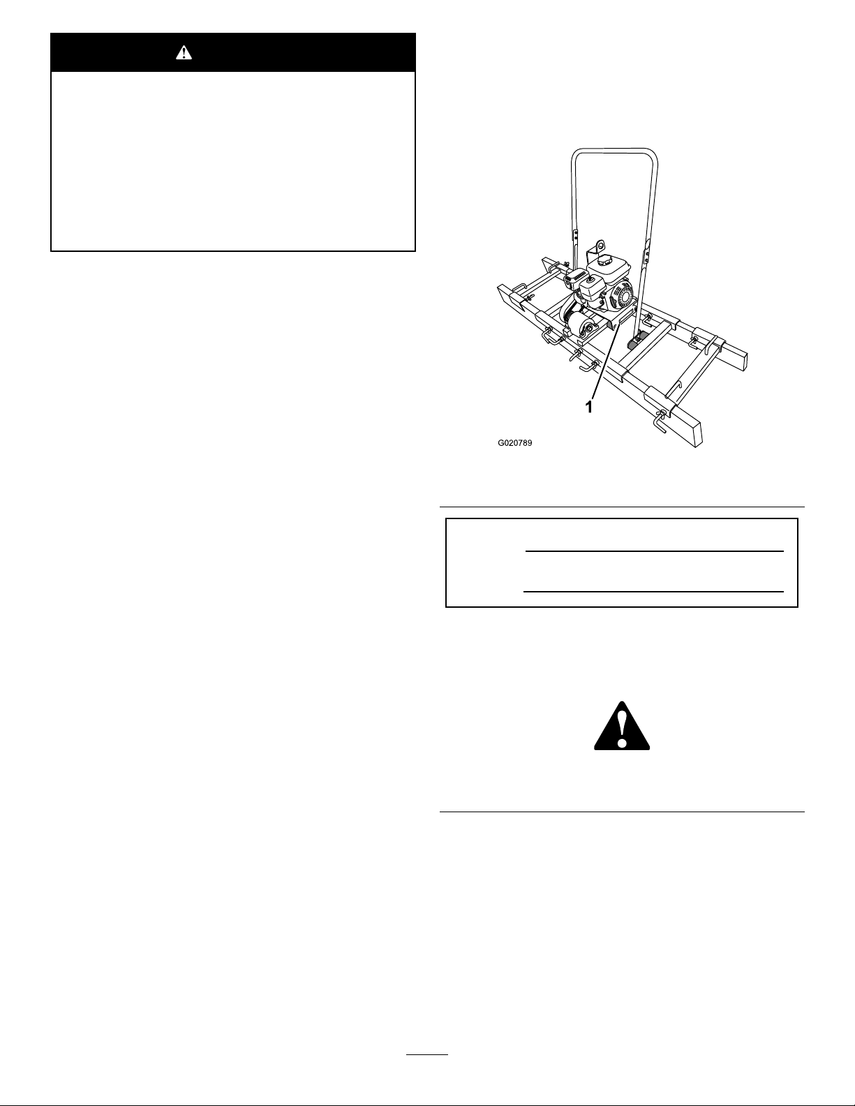
yourproductready.Figure1identiesthelocationofthe
modelandserialnumbersontheproduct.Writethenumbers
inthespaceprovided.
Theenclosed
Engine Owner's Man ual
issuppliedfor
informationregardingtheUSEnvironmentalProtection
Agency(EPA)andtheCaliforniaEmissionControl
Regulationofemissionsystems,maintenance,and
warranty.Replacementsmaybeorderedthroughthe
enginemanufacturer.
Introduction
Thismachineisavibratingconcretescreedintendedforuse
invariousconcrete-formingwork.Themachineisdesigned
tooperatewithavarietyofoperator-providedboardwidths
includingcontouredscreedboards.
Readthisinformationcarefullytolearnhowtooperateand
maintainyourproductproperlyandtoavoidinjuryand
productdamage.Youareresponsibleforoperatingthe
machineproperlyandsafely .
YoumaycontactTorodirectlyatwww .Toro.comforproduct
andaccessoryinformation,helpndingadealer,ortoregister
yourproduct.
Figure1
1.Modelandserialnumberlocation
ModelNo.
SerialNo.
Thismanualidentiespotentialhazardsandhassafety
messagesidentiedbythesafetyalertsymbol(Figure2),
whichsignalsahazardthatmaycauseseriousinjuryordeath
ifyoudonotfollowtherecommendedprecautions.
Figure2
1.Safetyalertsymbol
©2014—TheToro®Company
8111LyndaleAvenueSouth
Bloomington,MN55420
Thismanualuses2wordstohighlightinformation.
Importantcallsattentiontospecialmechanicalinformation
andNoteemphasizesgeneralinformationworthyofspecial
attention.
Contactusatwww.Toro.com.
2
PrintedintheUSA
AllRightsReserved
Page 3

Contents
Safety
Safety...........................................................................3
SafeOperatingPractices...........................................3
SafetyandInstructionalDecals.................................5
Setup............................................................................6
1InstallingtheHandlebar.........................................6
2InstallingtheTowRope.........................................6
3InstallingtheL-bolts.............................................6
4CheckingtheOilLevel...........................................7
ProductOverview..........................................................8
Controls................................................................8
Specications.........................................................9
Operation....................................................................10
PreparingtoUsetheMachine...................................10
OperatorPosition...................................................10
AddingFuel...........................................................10
CheckingtheEngineOilLevel.................................12
StartingandStoppingtheEngine..............................13
InstallingandRemovingtheScreedBoards................14
ScreedingaConcreteSurface...................................15
LiftingtheMachine................................................16
Maintenance.................................................................17
RecommendedMaintenanceSchedule(s)......................17
PremaintenanceProcedures........................................18
PreparingtheMachineforMaintenance.....................18
DisconnectingtheSpark-plugWire...........................18
Lubrication...............................................................18
GreasingtheMachine.............................................18
EngineMaintenance..................................................19
ServicingtheAirCleaner.........................................19
ChangingtheEngineOil.........................................20
ServicingtheSparkPlug..........................................21
FuelSystemMaintenance...........................................22
ServicingtheFuelSystem........................................22
DriveSystemMaintenance.........................................23
LubricatingtheClutch.............................................23
BeltMaintenance......................................................24
RemovingandInstallingtheBeltGuard.....................24
ServicingtheBelt...................................................25
ReplacingtheBelt...................................................25
Cleaning...................................................................27
CleaningtheMachine..............................................27
Storage........................................................................27
Troubleshooting...........................................................29
Improperuseormaintenancebytheoperatororowner
canresultininjury.Toreducethepotentialforinjury,
complywiththesesafetyinstructionsandalways
payattentiontothesafetyalertsymbol
means:
instruction.Failuretocomplywiththeinstructionmay
resultinpersonalinjuryordeath.
Caution
,
W ar ning
,or
Danger
,which
—personalsafety
SafeOperatingPractices
WARNING
Engineexhaustcontainscarbonmonoxide,an
odorless,deadlypoisonthatcankillyou.
Donotruntheengineindoorsorinanenclosed
area.
Training
•ReadtheOperator'sManualandothertrainingmaterial.If
theoperator(s)ormechanic(s)cannotreadEnglish,itis
theowner'sresponsibilitytoexplainthismaterialtothem.
•Becomefamiliarwiththesafeoperationofthemachine,
operatorcontrols,andsafetysigns.
•Alloperatorsandmechanicsshouldbetrained.The
ownerisresponsiblefortrainingtheusers.
•Neverletchildrenoruntrainedpeopleoperateorservice
themachine.Localregulationsmayrestricttheageof
theoperator.
•Theowner/usercanpreventandisresponsiblefor
accidentsorinjuriesoccurringtohimselforherself,other
peopleorproperty.
Preparation
•Wearappropriateclothingincludinghardhat,safety
glasses,longpants,safetyshoes,andhearingprotection.
Longhair,looseclothingorjewelrymaygettangledin
movingparts.
•Useextracarewhenhandlinggasolineandotherfuels.
Theyareammableandvaporsareexplosive.
–Useonlyanapproved-fuelcontainer.
–Neverremovethefuel-tankcaporaddfuelwiththe
enginerunning.
–Allowtheenginetocoolbeforefueling.
–Donotsmokewhilefueling.
–Neverrefuelordrainthemachineindoors.
•Checkthattheswitches,enginecontrols,andshieldsare
attachedandfunctioningproperly.Donotoperateunless
theyarefunctioningproperly.
3
Page 4

Operation
MaintenanceandStorage
•Neverrunanengineinanenclosedarea.
•Onlyoperatethemachineingoodlight.
•Onlystarttheenginefromtheoperator'sposition.
•Neveroperatewiththeguardsnotsecurelyinplace.
•Donotchangetheenginegovernorsettingoroverspeed
theengine.
•Stoponlevelgroundandshutofftheenginebefore
leavingtheoperator'spositionforanyreason.
•Keeppetsandbystandersawaywhileoperatingthe
machine.
•Donotoperatethemachineundertheinuenceof
alcoholordrugs.
•Usecarewhenloadingorunloadingthemachineintoa
trailerortruck.
•Movetheenginecontrolsinasmooth,steadymotion.
•Watchfortrafcwhenoperatingonornearroadways.
•Donottouchpartswhichmaybehotfromoperation.
Allowthemtocoolbeforeattemptingtomaintain,adjust,
orservice.
•Ensurethatyouoperatethemachineinareaswherethere
arenoobstaclesincloseproximitytotheoperator.Only
operatetheunitinareaswherethereissufcientclearance
fortheoperatortosafelymaneuvertheproduct.
•Donotplaceyourfeetunderthemachineorscreed
boards.
•Lightningcancausesevereinjuryordeath.Iflightning
isseenorthunderisheardinthearea,donotoperate
themachine;seekshelter.
•Stoptheengineandwaitforallmovementtostopbefore
adjusting,cleaning,orrepairingthemachine.
•Cleandebrisfromthemuferandenginetohelpprevent
res.Cleanupoilorfuelspillage.
•Lettheenginecoolbeforestoringthemachine,anddo
notstoreitnearanopename.
•Donotstorefuelnearamesordrainfuelfromthe
machineindoors.
•Neverallowuntrainedpersonneltoservicethemachine.
•Usejackstandstosupportmachinewhenrequired.
•Keephandsandfeetawayfrommovingparts.Ifpossible,
donotmakeadjustmentswiththeenginerunning.
•Keepallpartsingoodworkingcondition.Replaceall
wornordamageddecals.
•Keepallhardwareofthemachinetight.Keepthe
machineingoodcondition.
•Nevertamperwithsafetydevices.
•Whenpresent,cleanupoilorfuelspillage.
•Useextracarewhenhandlinggasolineandotherfuels.
Theyareammableandvaporsareexplosive.
–Storefuelinanapprovedcontainer.
–Donotremovethegascaporaddfuelwhilethe
engineisrunning.
–Allowtheenginetocoolbeforefuelingthemachine.
–Donotsmokewhilefuelingthemachine.
–Donotfuelthemachineindoors.
–Donotstorethemachineorfuelcontainerinside
wherethereisanopename,suchasnearawater
heaterorfurnace.
–Donotllacontainerwhileitisinsideavehicle,
trunk,pick-upbed,oranysurfaceotherthanthe
ground.
–Keepcontainernozzleincontactwiththetankduring
lling.
•Makeanynecessaryrepairstothemachinebeforestarting.
•UseonlygenuineTororeplacementpartstoensurethat
originalstandardsaremaintained.
4
Page 5
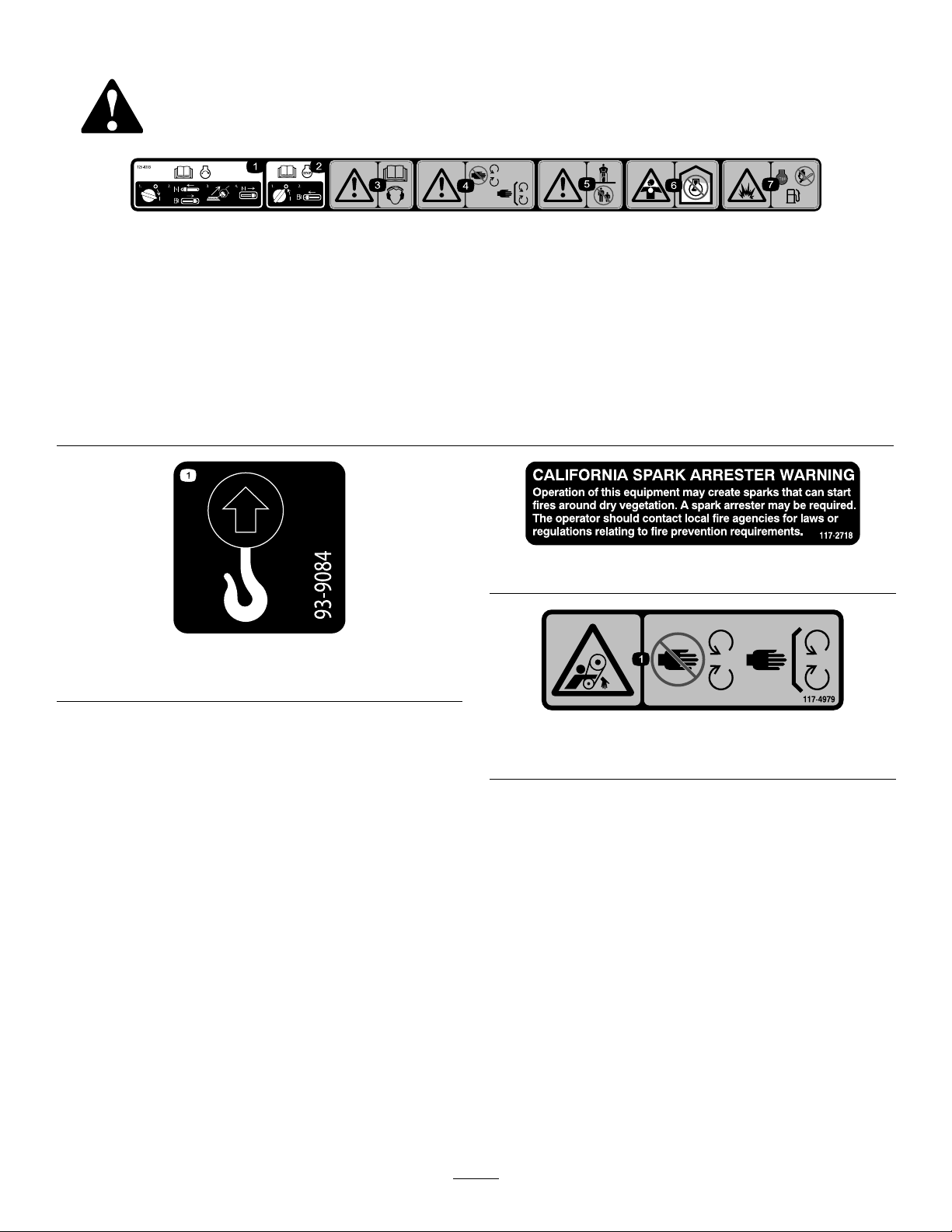
SafetyandInstructionalDecals
Safetydecalsandinstructionsareeasilyvisibletotheoperatorandarelocatednearanyareaofpotential
danger.Replaceanydecalthatisdamagedorlost.
125–8203
1.ReadtheOperator’sManualforinformationonstartingthe
engine—1)Turnontheengineswitch;2)Closethechoke
andturnonthefuelswitch;3)Pulltherecoilstarter;4)Open
thechoke.
2.ReadtheOperator’sManualforinformationonstoppingthe
engine—1)Turnofftheengineswitch;2)Turnoffthefuel
switch.
3.Warning—readtheOperator’sManual;wearhearing
protection.
4.Warning—keepawayfrommovingparts;keepallguardsand
shieldsinplace.
93-9084
1.Liftpoint
5.Warning—keepbystandersaway.
6.Chokinghazard—donotruntheengineinanunventilated
area.
7.Explosionhazard—stoptheengineandextinguishallames
beforerefueling.
117–2718
117–4979
1.Rotatingbelt—Keepguardinplace
5
Page 6
Setup
G020818
1
2
3
4
G020823
1
2
3
4
1
2
1
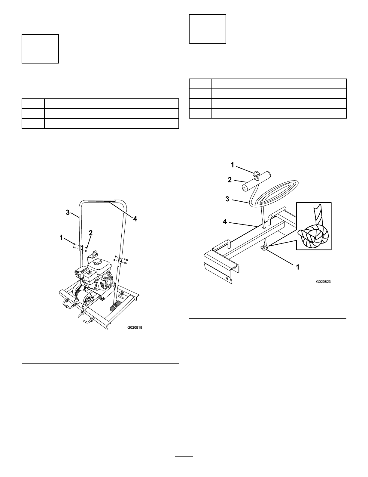
InstallingtheHandlebar
Partsneededforthisprocedure:
1Upperhandlebar
4
Bolt(5/16x1inch)
4
Nut(5/16inch)
Procedure
Placetheupperhandlebarsothatitcanbeinstalledusing
thenutsandbolts.(Figure3).
Note:Ensurethatthedecalisinthecorrectpositionsoit
canbereadbytheoperatorwhileintheoperatorsposition;
refertoFigure11.
InstallingtheTowRope
Partsneededforthisprocedure:
1
Leftspreader
1Rightspreader
2Pullgrip
2Rope
Procedure
1.Threadtheendoftheropethroughapullgrip(Figure
4).
Figure4
1.Pullgrip3.Rope
2.Overhandknot4.Spreader(right)
2.Tieanoverhandknotinthefreeendoftherope
Figure3
1.Bolt3.Upperhandlebar
2.Nut4.Decal
6
(Figure4).
3.Threadthefreeendoftheropethroughtheholeinthe
rightspreader(Figure4).
4.Tieanoverhandknotintheshortendoftherope.
5.Repeatsteps1and2withtheothersegmentofrope
andpullgrip.
6.Threadthelongendoftheropethroughtheholein
theleftspreader.
7.Tieanoverhandknotinthefreeendoftherope.
Page 7
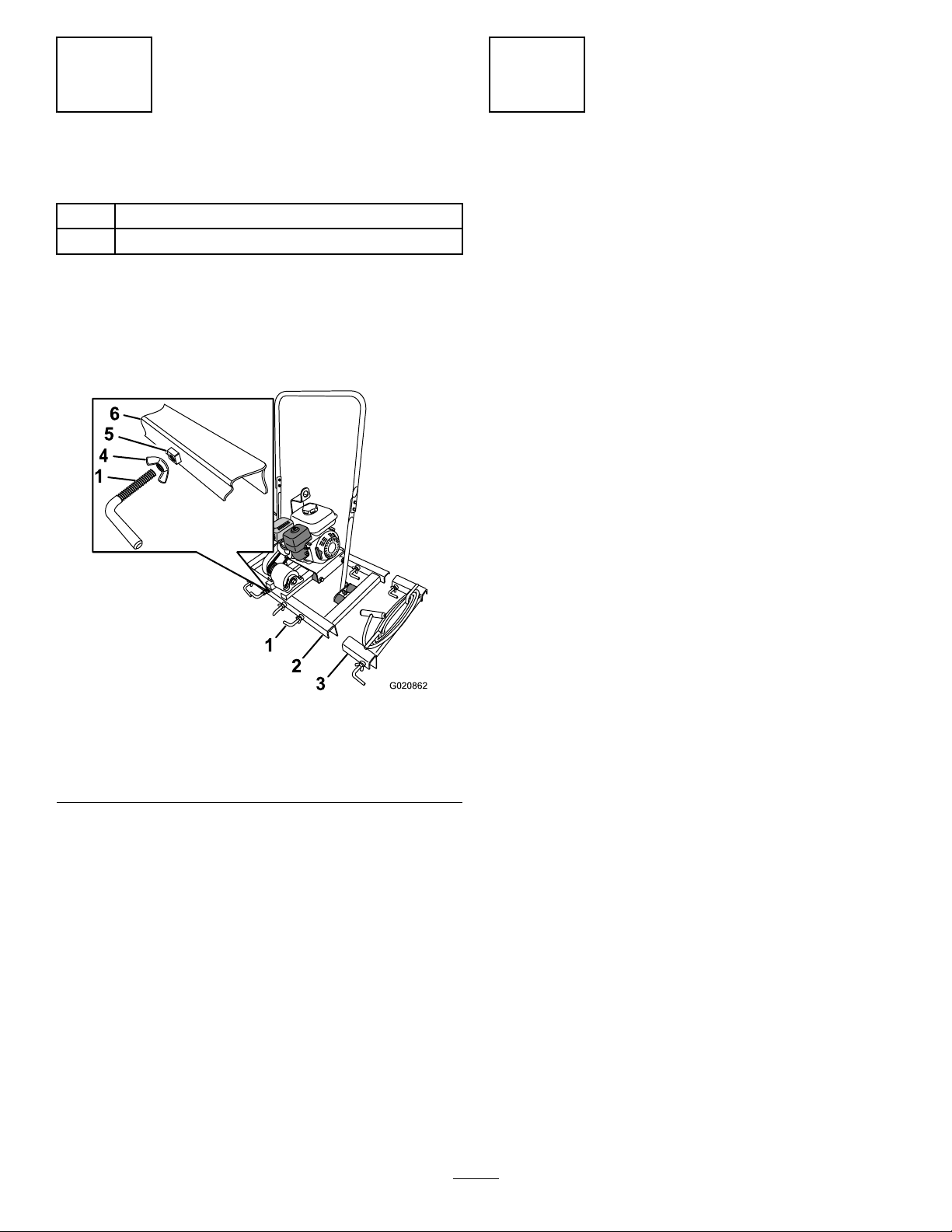
3
G020862
1
2
3
4
5
6
1
4
InstallingtheL-bolts
Partsneededforthisprocedure:
10L-bolt
10Wingnut
AssemblingtheL-boltstotheMachine
andSpreaders
1.Ifnotinstalled,threadthewingnutsontotheL-bolt
(Figure5).
CheckingtheOilLevel
NoPartsRequired
Procedure
Beforestartingtheengineforthersttime,checktheengine
oillevel;refertoCheckingtheEngineOilLevel(page12).
Figure5
1.L-bolt4.Wingnut
2.Channel(frame)
3.Channel(spreader)6.Channel
2.ThreadtheL-bolts2or3rotationsintotheweldnutsin
theU-channelsoftheframeandthespreaders(Figure
5).
5.Weldnut
7
Page 8
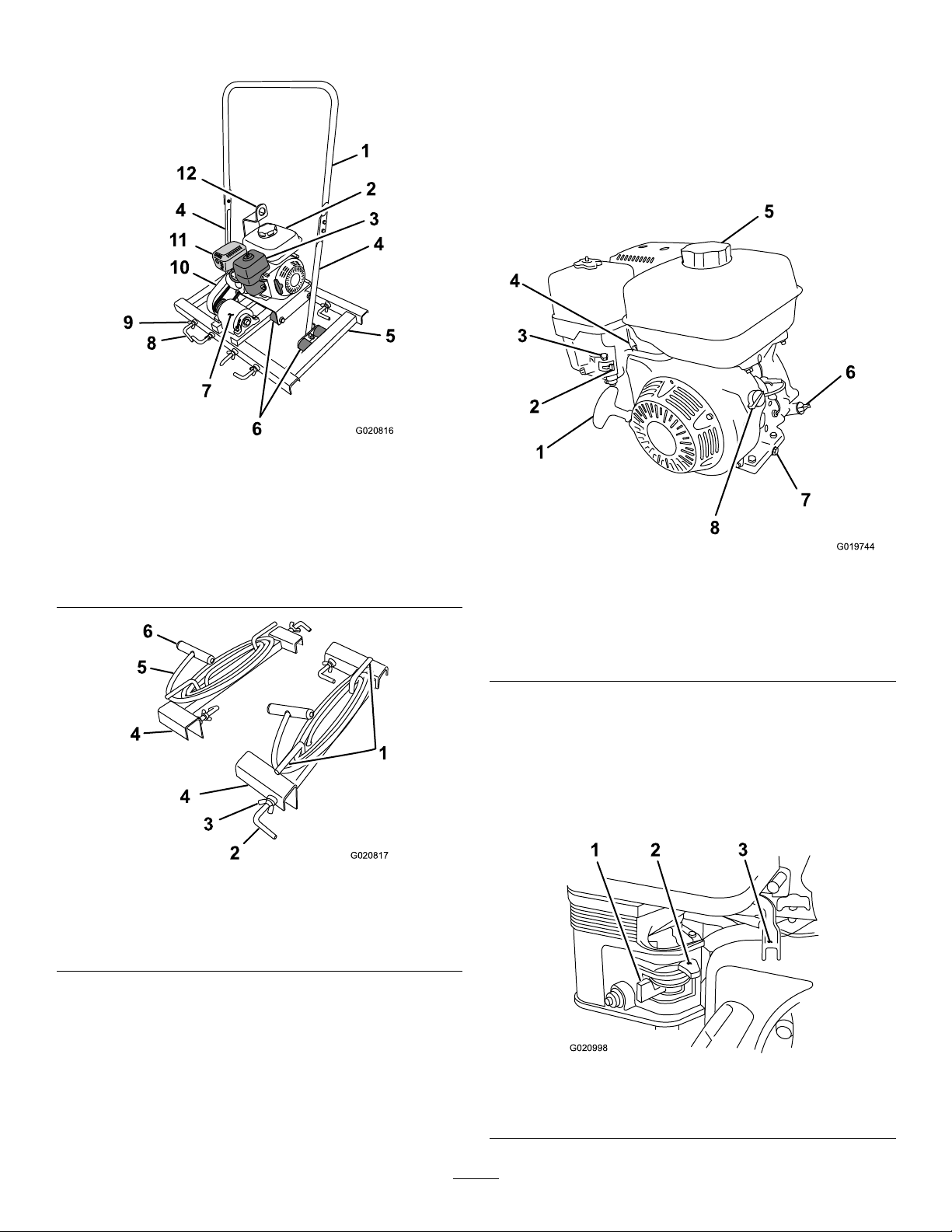
ProductOverview
1
2
4
4
5
6
7
8
9
10
11
12
3
G020816
6
5
4
4
3
2
1
G020817
1
2
3
4
5
6
7
8
G019744
G020998
1 2
3
Figure6
1.Upperhandlebar7.Eccentricguard
2.Fueltank8.L-bolt
3.Air-lterhousing
4.Lowerhandlebar10.Beltguard
5.Frame
6.Isolator
9.Wingnut
11.Mufer
12.Liftingbracket
Controls
Becomefamiliarwithalltheenginecontrolsbeforeyoustart
andoperatethemachine.
EngineControls
Figure8
1.Recoil-starthandle5.Fuelcap
2.Fuelvalve
3.Chokelever7.Oil-drainplug
4.Throttlelever
6.Oilcap/dipstick
8.On/Offswitch
Figure7
1.Cleat4.Channel(spreader)
2.L-bolt5.Rope
3.Wingnut6.Pullgrip
FuelValve
Thefuelvalve(Figure9)islocatedunderneaththechoke
lever.MovetheleverforthefuelvalvetotheOnposition
beforeattemptingtostarttheengine.Whenyouhavenished
screeding,stoptheengineandmovethefuelvalveleverto
theOffposition.
Figure9
1.Fuelvalve3.Throttlelever
2.Chokelever
8
Page 9
ChokeLever
OFF
ON
g018808
1
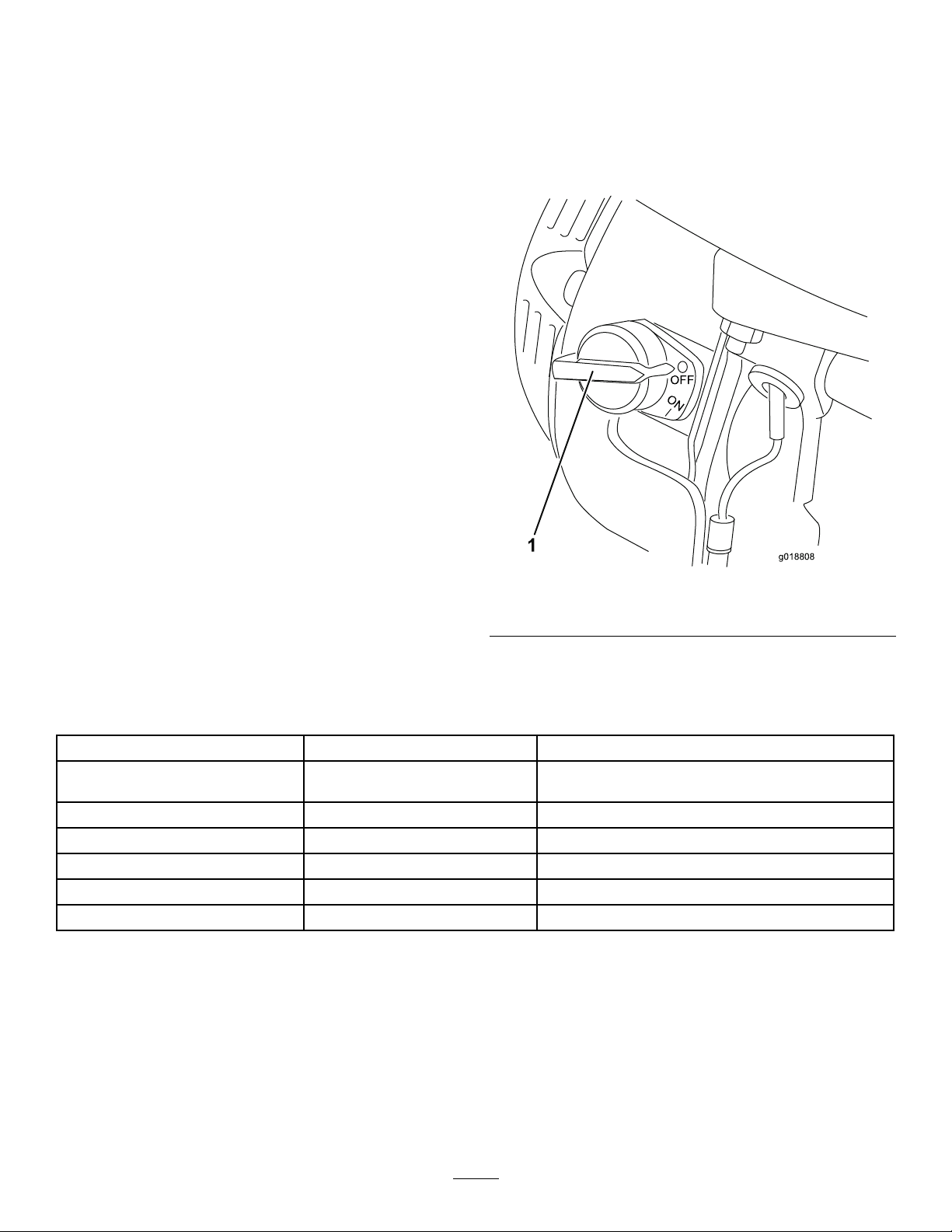
EngineOn/OffSwitch
Thechokelever(Figure9)isrequiredwhenstartingacold
engine.Beforepullingontherecoil-starthandle,move
thechokelevertotheclosedposition.Oncetheengineis
running,movethechokelevertotheopenposition.Do
notusethechokeiftheengineisalreadywarmeduporthe
airtemperatureishigh.
ThrottleLever
Thethrottlelever(Figure9)controlsthespeed(rpm)ofthe
engine.Itislocatednexttothechokelever.
Recoil-startHandle
Tostarttheengine,pulltherecoil-starthandle(Figure8)
quicklytoturntheengineover.Theenginecontrolsdescribed
abovemustallbesetcorrectlyfortheenginetostart.
Oil-levelSwitch
Theoil-levelswitchislocatedinsidetheengine,anditwill
notallowtheenginetorunwhenoillevelisbelowthesafe
operatinglimit.
TheOn/Offswitch(Figure10)allowstheoperatorofthe
machinetostartandstoptheengine.Thisswitchislocated
onthefrontoftheengine.Itismarkedl(On)andO(Off).
RotatetheOn/OffswitchtotheOnpositiontostartandrun
theengine.RotatetheOn/OffswitchtotheOffpositionto
stoptheengine.
Figure10
1.EngineOn/Offswitch
Specications
Note:Specicationsanddesignaresubjecttochangewithoutnotice.
Model68052Model68053
Width(withoutspreadersandscreed
board)
Length
Height(withoutscreedboard)122cm(48inch)122cm(48inch)
Weight(withoutscreedboard)53kg(116lb)61kg(134lb)
Screedboardthicknessandheight5cmx15–20cm(2inchx6–8inch)5cmx15–20cm(2inchx6–8inch)
Maximumscreedboardwidth
89cm(35inch)89cm(35inch)
56cm(22inch)56cm(22inch)
457cm(15ft)914cm(30ft)
9
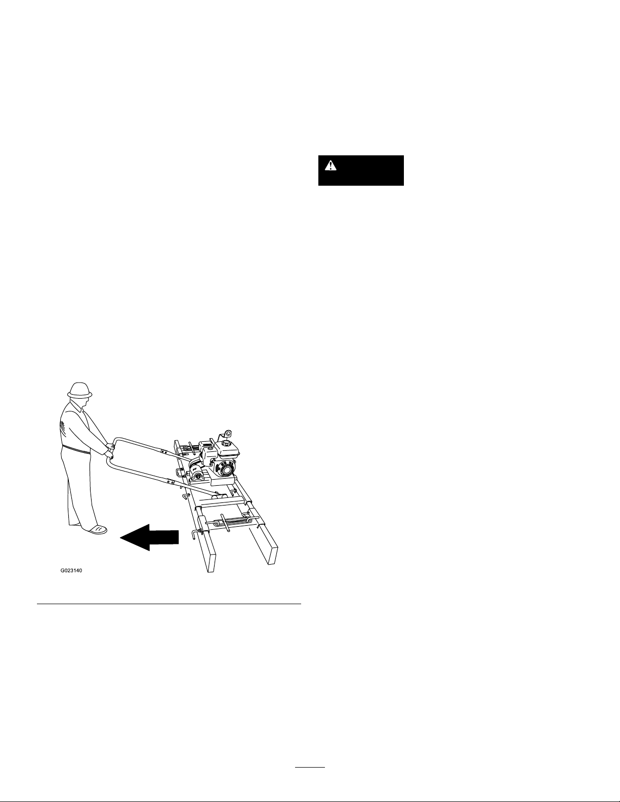
Page 10
Operation
G023140
Note:Determinetheleftandrightsidesofthemachine
fromthenormaloperatingposition.
Important:Beforeoperatingthemachine,checkthe
fuelandoillevels,andremovedebrisfromthemachine.
PreparingtoUsetheMachine
•Reviewallofthesafetydecalsonthemachine.
•Useahardhat,hearingprotection,tight-ttinggloves
withoutdrawstringsorloosecuffs,andeyeprotection.
Ameshvisoralonedoesnotprovidesufcienteye
protection;supplementwithprotectiveglasses.
•Ensurethatyouarefamiliarwithsafetyregulationsand
theshutdownproceduresdescribedintheOperator’s
ManualandtheEngineManual.
•Ensurethatallguardsareinplaceandingoodcondition.
•Ensurethatthescreedboardsareingoodcondition,
alignedcorrectlyandsecuretothemachineandspreaders.
•Checkthefuelandoillevelsoftheengine.
OperatorPosition
Youmustbefamiliarwiththeoperatingpositionwhenusing
themachine(Figure11).
and/orenginedamagewhichmaynotbecoveredunder
warranty.
•Donotusegasolinecontainingmethanol.
•Donotstorefueleitherinthefueltankorfuelcontainers
overthewinterunlessafuelstabilizerisused.
•Donotaddoiltogasoline.
DANGER
Incertainconditions,gasolineisextremely
ammableandhighlyexplosive.Areorexplosion
fromgasolinecanburnyouandothersandcan
damageproperty.
•Fillthefueltankoutdoors,inanopenarea,
whentheengineiscold.Wipeupanygasoline
thatspills.
•Neverllthefueltankinsideanenclosedtrailer.
•Donotllthefueltankcompletelyfull.Add
gasolinetothefueltankuntilthelevelisno
higherthanthescreenonthelterinthefuel
tank.Thisemptyspaceinthetankallows
gasolinetoexpand.
Figure11
AddingFuel
ETHANOL:Gasolinewithupto10%ethanol(gasohol)
or15%MTBE(methyltertiarybutylether)byvolumeis
acceptable.EthanolandMTBEarenotthesame.Gasoline
with15%ethanol(E15)byvolumeisnotapprovedforuse.
Neverusegasolinethatcontainsmorethan10%ethanolby
volume,suchasE15(contains15%ethanol),E20(contains
20%ethanol),orE85(containsupto85%ethanol).Using
unapprovedgasolinemaycauseperformanceproblems
•Neversmokewhenhandlinggasoline,andstay
awayfromanopenameorwheregasoline
fumesmaybeignitedbyaspark.
•Storegasolineinanapprovedcontainerand
keepitoutofthereachofchildren.Neverbuy
morethana30-daysupplyofgasoline.
•Donotoperatethemachinewithoutentire
exhaustsysteminplaceandinproperworking
condition.
10
Page 11

DANGER
1
G019799
Incertainconditionsduringfueling,static
electricitycanbereleasedcausingasparkwhich
canignitethegasolinevapors.Areorexplosion
fromgasolinecanburnyouandothersandcan
damageproperty.
•Alwaysplacethegasolinecontainersonthe
groundawayfromyourvehiclebeforelling.
•Donotllgasolinecontainersinsideavehicleor
onatruckortrailerbedbecauseinteriorcarpets
orplastictruckbedlinersmayinsulatethe
containerandslowthelossofanystaticcharge.
•Whenpractical,removegas-poweredequipment
fromthetruckortrailerandrefuelthemachine
ontheground.
•Ifthisisnotpossible,thenrefuelsuch
equipmentonatruckortrailerfromaportable
container,ratherthanfromagasolinedispenser
nozzle.
Addthecorrectamountoffuelstabilizer/conditionertothe
fuel,andfollowthedirectionsofthemanufacturerofthe
stabilizer.
Note:Fuelstabilizer/conditionerismosteffectivewhen
mixedwithfreshgasoline.Tominimizethechanceofvarnish
depositsinthefuelsystem,usefuelstabilizeratalltimes.
FillingtheFuelTank
Fueltankcapacity:3.1L(0.82USgallon)
Important:Theunusedspaceinthetankallowsthe
gasolinetoexpandwithchangesintemperature.Donot
llthefueltankcompletelyfull.
1.Parkthemachineonalevelsurface,stoptheengine,
andallowtheenginetocool.
2.Cleanaroundthefuelcapandremoveit(Figure12).
•Ifagasolinedispensernozzlemustbeused,
keepthenozzleincontactwiththerimofthe
fueltankorcontaineropeningatalltimesuntil
fuelingiscomplete.
WARNING
Gasolineisharmfulorfatalifswallowed.Long-term
exposuretovaporscancauseseriousinjuryand
illness.
•Avoidprolongedbreathingofvapors.
•Keepfaceawayfromnozzleandgastankor
fuel-containeropening.
•Keepgasawayfromeyesandskin.
Important:Donotmixoilwiththefuel.
RecommendedFuel
UnleadedGasoline
U.S.
Except
U.S.
Pumpoctanerating87orhigher
Researchoctanerating92orhigher
Pumpoctanerating87orhigher
Figure12
1.Fuelcap
3.Addunleadedgasolinetothefueltank,untilthelevel
isatthebottomofthemaximumfuellevelasshown
inFigure13.
UsingFuelStabilizer/Conditioner
Useafuelstabilizer/conditionerinthemachinetokeepthe
fuelfreshduringstorage.
Important:Donotusefueladditivescontaining
methanolorethanol.
11
Page 12

G020679
1
Figure13
g013375
0 20 40 60 80 100 F
-20 -10 0 10 20 30 40 C
o
o
30
5W - 30 / 10W - 30
1
2
3
4
G019746
1.Maximumfuellevel
4.Installthefuelcapsecurely(Figure12).
5.Wipeupanygasolinethatmayhavespilled.
CheckingtheEngineOilLevel
Figure14
Note:T oroPremiumEngineOilisavailablefromyour
AuthorizedT oroDealer.
1.Placethemachineonaat,levelsurface,andstopthe
engine.
2.Allowtheenginetocool.
3.Cleanaroundtheoildipstick.
4.Removetheoilcap/dipstickandwipetheendclean
(Figure15).
ServiceInterval:Beforeeachuseordaily
Important:Use4-cyclemotoroilthatmeetsorexceeds
therequirementsforAPIservicecategory
equivalent).AlwayschecktheAPIservicelabelonthe
oilcontainertobesureitincludestheSJorlater(or
equivalent)rating.
Donotoverllthecrankcasewithoilbecausetheengine
maybedamaged.
Runningtheenginewithalowoillevelcancauseengine
damage.Thistypeofdamageisnotcoveredbythe
warranty.
Note:SAE10W -30isrecommendedforgeneraluse.The
otheroilviscositiesshowninthechartmaybeusedwhenthe
averagetemperatureinyourareaiswithintheindicatedrange.
SJ or later
(or
Figure15
1.Fillport
2.Oilcap/dipstick4.Oillevel(lowerlimit)
3.Oillevel(upperlimit)
5.Slidethedipstickfullyintothellportwithout
threadingitintotheport(Figure15).
6.Removethedipstickandlookattheend.Iftheengine
oillevelislow ,slowlypouronlyenoughoilintothell
porttoraisetheleveltotheFullmarkonthedipstick
(Figure15).
7.Replaceandsecurethedipstick(Figure15).
12
Page 13

StartingandStoppingthe
G019815
1
2
3
G019747
Engine
StartingtheEngine
1.Ontheengine,movethethrottleleverawayfromthe
Minposition,1/3ofthewaytowardtheMaxposition
(Figure16);refertoThrottleLever(page9).
Figure17
Note:IfthechokeleverissettotheClosedpositiontostart
theengine,graduallymovethechokeleverbacktowardthe
Openpositionastheenginewarmsup.Iftheenginestalls
orhesitates,movethechokeleverbacktowardtheClosed
positionuntiltheenginerunssmooth.Allowtheengineto
warmup,thenmovethechokelevertotheOpenposition;
refertoChokeLever(page9).
Figure16
1.Chokelever
2.Fuelvalve
2.MovetheleverofthefuelvalvetotheOnposition—all
thewaytotheright(Figure16);refertoFuelValve
(page8).
3.Positionthechokeleverasfollows:
3.Throttlelever
•Tostartacoldengine,movethechokelevertothe
Closedposition—allthewaytotheleft(Figure16);
refertoChokeLever(page9).
•Tostartawarmengine,movethechokeleverin
theOpenposition—allthewaytotheright.
4.RotatetheengineswitchtotheOnposition(Figure
16);refertoEngineOn/OffSwitch(page9).
StoppingtheEngine
WARNING
Inanemergencysituation,stoptheengine
immediately.
Important:Duringnormaloperation,iftheengine
hasbeenworkinghardorishot,letitidleforaminute
beforestoppingtheengine.Thishelpstocoolthe
enginebeforestopping .
1.EnsurethatthechokeleverisintheOffposition
(Figure16);refertoChokeLever(page9).
2.MovethethrottlelevertotheMinposition(Figure16);
refertoThrottleLever(page9).
3.RotatetheengineswitchtotheOffposition;referto
EngineOn/OffSwitch(page9).
5.Pulltherecoil-starthandlelightlyuntilyoufeel
resistance,thenpullthehandlebriskly(Figure17).
Note:Returntherecoil-starthandlegently.
13
Page 14

InstallingandRemovingthe
G020865
5
8
9
5
3
4
7
2
6
ScreedBoards
5.Raisetherearofthemachine10to12inches,and
aligntherearscreedboardtotherearU-channelof
theframe(Figure18).
Note:Usestraight5cmx15to20cm(2inchx6to8inch)
boardsor2-inchthickcontouredmaterial.
Maximumscreedboardwidths:
•Model68052—457cm(15ft)
•Model68053—914cm(30ft)
InstallingtheScreedBoardstothe
Machine
1.Placethemachineonalevel,atsurface.
2.Raisethefrontofthemachine10to12inches,
andaligntheforwardscreedboardtotheforward
U-channeloftheframe(Figure18).
Note:ThefrontU-channelislocatedadjacenttothe
eccentriccover.
6.AlignthescreedboardtotheU-channel,andcenter
theboardtothemachine(Figure18).
7.Securethescreedboardtothemachinebytightening
alltheL-boltsandwingnuts(Figure18).
InstallingtheSpreaders
SpreaderPositionTable
Screed
board
length
Spreader
position
(fromthe
endofthe
screed
board)
457cm
(15ft)
61cm
(2ft)
1.UsingtheSpreaderPositionTable,locateandmarkthe
positionsofthespreadersonbothendsofthescreed
board.
2.Alignchannelsofthespreadertothescreedboards
andseatthespreaderontotheboards(Figure18).
3.Slidethespreaderalongtheboardsuntiltheoutside
edgeofthespreaderisalignedwiththemarkonthe
boardcreatedinstep1.
610cm
(20ft)
91cm
(3ft)
762cm
(25ft)
122cm
(4ft)
914cm
(30ft)
152cm
(5ft)
Figure18
1.U-channel(rightspreader)
2.Eccentricguard7.U-channel
3.U-channel(frame)
4.U-channel(leftspreader)
5.Forwardscreedboard
6.Rearscreedboard
8.Wingnut
9.L-bolt
3.AlignthescreedboardtotheU-channelandcenterthe
boardthemachine(Figure18).
4.LightlytightentheL-boltsintheforwardU-channel
(Figure18).
4.Securethespreadertothescreedboardswiththe
L-boltsandwingnuts(Figure18).
5.Attachthespreadertotheotherendofthescreed
boardbyrepeatingsteps2,3,and4.
RemovingtheSpreadersandScreed
Boards
1.Placethemachineonalevel,atsurface.
2.LoosenthewingnutsandL-boltsthatsecurethe
spreaderstothescreedboards,andremovethe
spreaders(Figure18).
3.Raisetherearofthemachine10to12inches,and
removetherearscreedboardfromtherearU-channel
oftheframe(Figure18).
4.LoosenthewingnutsandL-boltsthatsecuretherear
screedboardtotherearU-channeloftheframe,and
removethescreedboard(Figure18).
5.Raisethefrontofthemachine10to12inches,and
removetheforwardscreedboardfromtheforward
U-channeloftheframe(Figure18).
6.LoosenthewingnutsandL-boltsthatsecurethe
forwardscreedboardtotheforwardU-channelofthe
frame,andremovethescreedboard(Figure18).
7.Carefullylowerthemachine.
14
Page 15

ScreedingaConcreteSurface
G020895
1
2
3
4
5
G020886
LevelingtheConcreteSurface
Thisprocedurelevelsafreshlypouredconcreteprojectto
theformheight.
Note:Theforwardscreedboardislocatedadjacenttothe
eccentricguard.
1.Liftandalignthescreedontotheendoftheconcrete
formswiththeforwardscreedboardatthefrontof
thescreedpass.
2.Starttheengine;refertoStartingtheEngine(page13).
3.MovethethrottlelevertotheFastposition;referto
ThrottleLever(page9).
4.Pullthescreedinslow,steadymotionalongthe
concreteforms(Figure20).
Note:Ensurethatanadequateamountofconcreteis
loadedaheadoftheforwardscreedboardfortheentire
screedingpass.
Figure20
Figure19
1.Forwardscreedboard
2.Handlebar5.Rearscreedboard
3.Eccentricguard
4.Liftbracket
Note:Useadditionalpeopletomovethescreedby
havingthempullthescreedwiththetowgripsand
ropesthatareattachedtothespreaders(Figure20).
5.Attheendofthescreedpass,movetheenginethrottle
totheidlepositionandallowtheenginetoidlefor1
minute.
6.Stoptheengineandmovethescreedofftheforms;
refertoStoppingtheEngine(page13).
7.Cleanthescreedofcement,sand,andaggregateafter
eachpasswithwaterandasoft-bristlebrush.
15
Page 16

LiftingtheMachine
G020991
1
2
MovingtheMachinewiththeLifting
Plate
Important:Useliftingequipmentwitha61kg(134lb)
orgreaterliftcapacity.
1.Removethespreadersandscreedboardsfromthe
machine;refertoRemovingtheSpreadersandScreed
Boards(page14).
2.MovetheleverforthefuelvalvetotheOffposition,
refertoFuelValve(page8).
3.Alignthehook,strap,orcableoftheliftingequipment
totheholeintheliftingbracket(Figure21).
Figure21
1.Liftingequipment2.Liftbracket
4.Raisethemachineandmoveittothedesiredlocation.
5.Carefullylowerthemachine.
6.Removetheliftingequipment(Figure21).
16
Page 17

Maintenance
Note:Determinetheleftandrightsidesofthemachinefromthenormaloperatingposition.
RecommendedMaintenanceSchedule(s)
MaintenanceService
Interval
Aftertherst25hours
Aftertherst50hours
Beforeeachuseordaily
Aftereachuse
Every25hours
Every50hours
Every100hours
Every300hours
Monthly
MaintenanceProcedure
•Inspectandadjustthebelt.
•Changetheoil.
•Checktheengineoillevel.
•Greasethemachine.
•Inspecttheaircleanerelements.
•Checkforloosefasteners.
•Cleanthemachine.
•Changetheoilwhenoperatedunderheavyloadsorinhightemperatures.
•Cleantheairlterelements.Cleanthemmorefrequentlyindustyoperating
conditions.
•Changetheoil.
•Checkthesparkplug.
•Cleanthesedimentcup.
•Replacethepaperaircleanerelement.Replaceitmorefrequentlyindustyoperating
conditions.
•Replacethesparkplug.
•Lubricatetheclutch.
•Inspectandadjustthebelt.
Yearlyorbeforestorage
Important:Refertoyour
•Changetheoil.
•Cleanthefuelsedimentcup.
•T ouchupchippedpaint
Engine Operator's Man ual
foradditionalmaintenanceprocedures.
17
Page 18
CAUTION
G019281
1
G020901
4
5
2
2
3
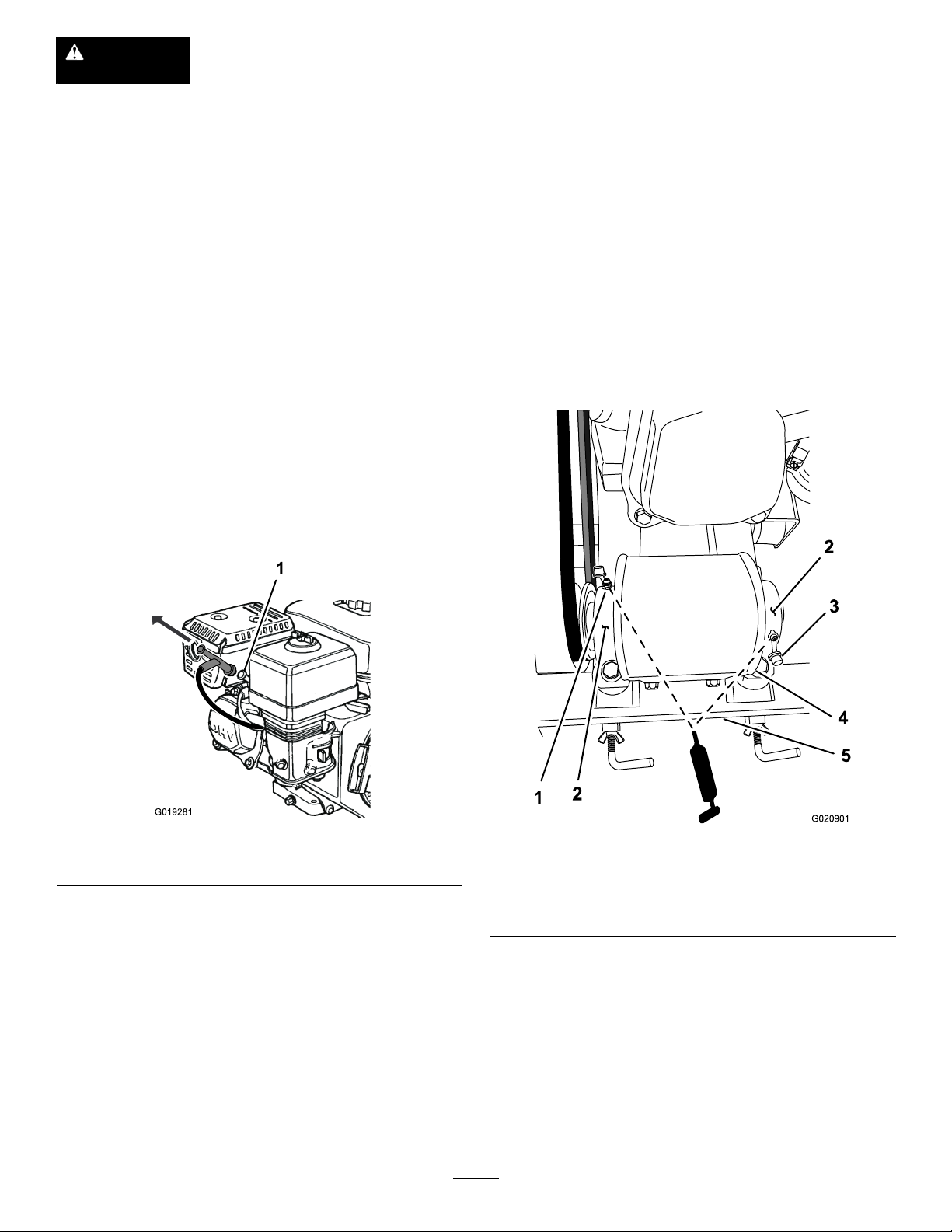
Disconnectthewiresfromthesparkplugsbeforeyoudoanymaintenance.Setthewiresasidesothat
theydonotaccidentallycontactthesparkplugs.
Premaintenance
Procedures
PreparingtheMachinefor Maintenance
1.Movethemachinetoalevelsurface.
2.Ensurethattheengineandmuferarecool.
3.Removethesparkplugwire,refertoDisconnectingthe
Spark-plugWire(page18).
DisconnectingtheSpark-plug Wire
Pullthespark-plugwireofftheterminalofthesparkplug
(Figure22).
Lubrication
GreasingtheMachine
ServiceInterval:Beforeeachuseordaily
Greaseeccentricbearingsevery8operatinghoursand
immediatelyaftereverywashing.
GreaseType:Lithium-basedgrease.
1.Locatethesupportbearingsattheleftandrightsides
oftheeccentricguard(Figure23).
Figure22
1.Sparkplug
1.Greasetting
2.Supportbearing5.Channel(frame)
3.Dustcap
2.Openthedustcapsthatcoverthegreasettingsthat
inthesupportbearings(Figure23).
3.Cleanthegreasettingswitharag.
4.Connectagreaseguntoeachtting(Figure23).
5.Pumpgreaseintothettingsuntilgreasebeginsto
oozeoutofthebearings(approximately1or2pumps).
6.Wipeupanyexcessgreasewithacleanrag.
7.Closethedustcaps(Figure23).
18
Figure23
4.Eccentricguard
Page 19

EngineMaintenance
1
2
3
4
5
6
G019728
Note:Becarefultopreventdirtanddebrisfrom
fallingintothebase.
ServicingtheAirCleaner
ServiceInterval:Beforeeachuseordaily—Inspecttheair
cleanerelements.
Every50hours—Cleantheairlterelements.Clean
themmorefrequentlyindustyoperatingconditions.
Every300hours/Yearly(whichevercomes
rst)—Replacethepaperaircleanerelement.Replace
itmorefrequentlyindustyoperatingconditions.
Important:Donotoperatetheenginewithouttheair
lterassembly;extremeenginedamagewilloccur.
1.Stoptheengineandwaitforallmovingpartstostop.
2.Disconnectthewirefromthesparkplug;referto.
3.Removethenutthatsecuresthecover(Figure24).
5.Removethefoamandpaperelementsfromthebase
(Figure24).
6.Removethefoamelementfromthepaperelement
(Figure24).
7.Inspectthefoamandpaperelements,andreplacethem
iftheyaredamagedorexcessivelydirty.
8.Ifthepaperelementisexcessivelydirty,replaceit.
Note:Nevertrytobrushdirtoffthepaperelement;
brushingforcesthedirtintothebers.
9.Cleanthefoamelementinwarm,soapywaterorin
anonammablesolvent.
Note:Donotusegasolinetocleanthefoamelement
becauseitcouldcreateariskofreorexplosion.
10.Rinseanddrythefoamelementthoroughly.
11.Dipthefoamelementincleanengineoil,thensqueeze
outtheexcessoil.
Note:Excessoilinthefoamelementrestrictstheair
owthroughtheelementandmayreachthepaper
lterandclogit.
12.Wipedirtfromthebaseandthecoverwithamoistrag.
Note:Becarefultopreventdirtanddebrisfrom
enteringtheairductleadingtothecarburetor.
13.Installtheaircleanerelementsandensurethattheyare
properlypositioned.
14.Securelyinstallthecoverwiththenut.
Figure24
1.Covernut
2.Cover
4.Removethecover.
3.Wingnut5.Paperelement
4.Foamelement6.Base
19
Page 20
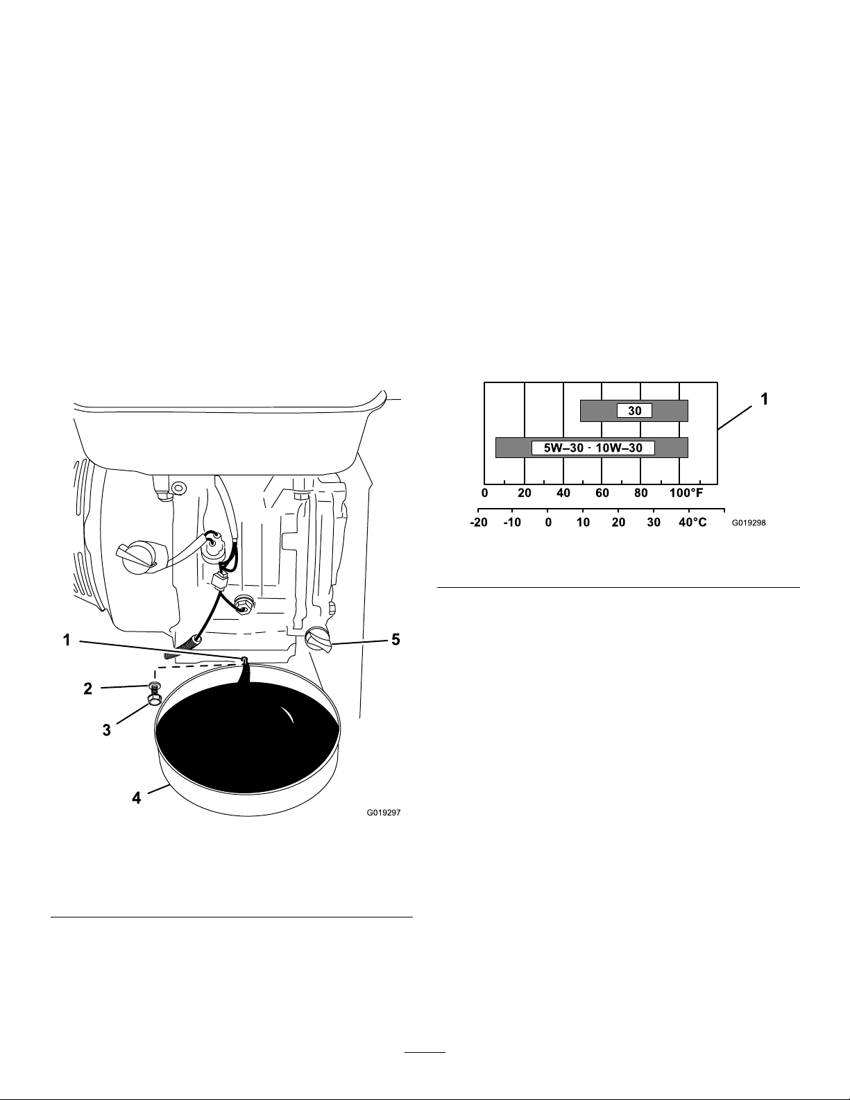
ChangingtheEngineOil
G019297
1
2
3
4
5
0 20 40 60
80
10 0°F
-20 -10 0 10 20 30 40 °C
5W–30 · 10 W– 30
30
1
G019298
ServiceInterval:Aftertherst50hours/Monthly
(whichevercomesrst)—Changetheoil.
Every100hours/Every6months(whichevercomes
rst)—Changetheoil.
Every25hours—Changetheoilwhenoperatedunder
heavyloadsorinhightemperatures.
Yearlyorbeforestorage—Changetheoil.
DrainingtheEngineOil
1.Starttheengineandletitrunveminutes;referto
StartingtheEngine(page13).
Note:Thiswarmstheoilsoitdrainsbetter.
2.Placeadrainpan,witha1.9L(2USqt)capacityor
greater,undertheoil-drainportoftheengine(Figure
25).
Note:Disposeoftheusedoilatacertiedrecycling
center.
FillingtheEngineCrankcasewithOil
Important:Use4-strokemotoroilthatmeetsorexceeds
therequirementsforAPIservicecategory
equivalent).AlwayschecktheAPIservicelabelonthe
oilcontainertobesureitincludestheSJorlater(or
equivalent).
Runningtheenginewithalowoillevelcancauseengine
damage.Thistypeofdamageisnotcoveredbywarranty.
Donotoverllthecrankcasewithoilbecausetheengine
maybedamaged.
Note:SAE10W-30isrecommendedforgeneraluse.
Otherviscositiesshowninthechartmaybeusedwhenthe
averagetemperatureinyourareaiswithintheindicatedrange.
Crankcaseoilcapacity:0.85L(0.61USqt)
SJ or later
(or
Figure26
1.Oilviscosityrangeforambientoperatingtemperatures
ToroPremiumEngineOilisavailablefromyourAuthorized
ToroDealer.
1.Removetheoilcap/dipstick(Figure27).
Figure25
1.Drainport4.Drainpan
2.Washer
3.Drainplug
5.Oilcap/dipstick
3.Removethedrainplugandwasher,anddraintheoil
(Figure25).
4.Whentheoilhasdrainedcompletely,installthedrain
plugwithanewwasher,andwipeupanyspilledoil
(Figure25).
20
Page 21

1
2
3
4
G019746
Figure28
G019749
Figure27
1.Fillport
2.Oilcap/dipstick4.Oillevel(lowerlimit)
3.Oillevel(upperlimit)
2.Slowlypourapproximately80%ofthespecied
amountofoilintothellport(Figure27).
3.Addadditionaloiltobringtheoilleveltotheupper
limitmarkonthedipstick;refertoCheckingthe
EngineOilLevel(page12).
4.Installtheoilcap/dipstick(Figure27).
ServicingtheSparkPlug
ServiceInterval:Every100hours/Every6months
(whichevercomesrst)—Checkthe
sparkplug.
Every300hours/Yearly(whichevercomes
rst)—Replacethesparkplug.
Note:Usea20mm(13/16inch)sparkplugwrenchfor
removingandinstallingthesparkplug.
RemovingtheSparkPlug
1.Parkthemachineonalevelsurfaceandturnoffthe
engine;refertoStoppingtheEngine(page13).
2.Ensurethatthemachinesurfacesarecool.
3.Pullthespark-plugwireofftheterminalofthespark
plug(Figure28).
1.Sparkplug
2.Wire
4.Cleanaroundthesparkplug.
5.Rotatethesparkplugcounterclockwiseusinga20mm
(13/16inch)spark-plugwrenchtoremovetheplug
andsealingwasher(Figure29).
Figure29
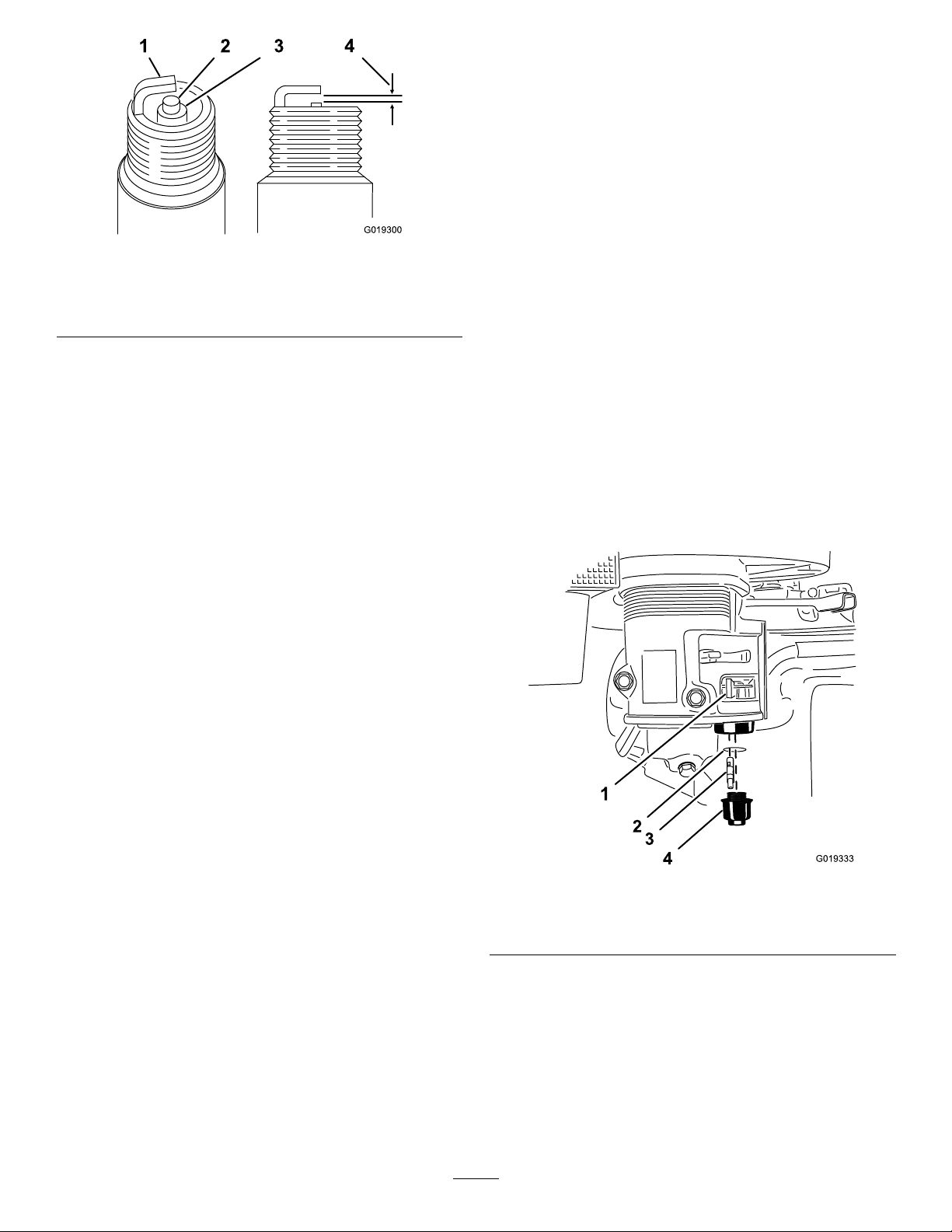
CheckingtheSparkPlug
Note:Useagappingtool/feelergaugetocheckandadjust
theairgap.Installanewsparkplugifnecessary.
AirGap:0.7to0.8mm(0.028to0.031inch)
Sparkplugtype:BPR6ES(NKG)orequivalent
1.Lookatthecenterofthesparkplug(Figure30).Ifyou
seelightbrownorgrayontheinsulator,theengineis
operatingproperly.
Important:Nevercleanthesparkplug.Always
replacethesparkplugwhenithasablackcoating,
wornelectrodes,anoilylm,orcracks.
21
Page 22
G019300
1 2
4
3
Figure30
2
3
4
1
G019333
1.Sideelectrode
2.Centerelectrode4.0.7to0.8mm(0.028to
2.Useagappingtoolforsparkplugsorafeelergaugeto
measurethegapbetweenthesideelectrodeandcenter
electrode(Figure30).
3.Ifthemeasuredgapisnotwithinthespeciedrange,
dothefollowing:
A.Ifthegapistoosmall,carefullybendtheside
electrodeawayfromthecenterelectrodeuntilthe
gapbetweentheelectrodesiswithinthemeasured
airgaprange.
B.Ifthegapistoolarge,carefullybendtheside
electrodetowardfromthecenterelectrodeuntil
thegapbetweentheelectrodesiswithinthe
measuredairgaprange.
3.Insulator
0.031inch)gap
FuelSystem
Maintenance
ServicingtheFuelSystem
CleaningtheSedimentCup
ServiceInterval:Every100hours/Every6months
(whichevercomesrst)—Cleanthe
sedimentcup.
Yearlyorbeforestorage—Cleanthefuelsedimentcup.
Underneaththefuelvalveisasedimentcuptocatchdirtin
thefuel.
1.Parkthemachineonalevelsurfaceandstoptheengine;
refertoStoppingtheEngine(page13).
2.Ensurethattheengineandtheexhaustsystemsurfaces
arecool.
3.MovetheleverofthefuelvalvetotheOffposition,all
thewaytotheleft(Figure31).
4.Unscrewthesedimentcup.
5.RemovethefuellterandO-ring(Figure31).
Note:MakesurenottomisplacetheO-ring
InstallingtheSparkPlug
Important:Ensurethatthegapbetweenthesideand
centerelectrodesiscorrectbeforeinstallingthespark
plug.
1.Threadthesparkplugclockwiseintothespark-plug
holebyhand.
Note:Avoidcrossthreadingthesparkplugwiththe
threadsofthespark-plughole.
2.Rotatesparkplugclockwiseusinga20mm(13/16
inch)spark-plugwrenchuntiltheplugandsealing
washerareseated(Figure29).
3.Tightentheplugasfollows:
•Wheninstallinganin-servicesparkplug,tighten
thepluganadditional1/8to1/4turn.
•Wheninstallinganewsparkplug,tightentheplug
anadditional1/2turn.
4.Installthespark-plugwirepushingthewireontothe
terminaloftheplug(Figure28).
Figure31
1.Fuelvalve(Off)3.Fuellter
2.O-ring4.Sedimentcup
Note:DonotcleantheO-ringinsolvent.
6.Cleanthefuellterandsedimentcupusinga
nonammablesolventanddrycarefully.
7.WipetheO-ringwithaclean,drycloth.
8.Installthefuellterinthebottomofthecarburetor
(Figure31).
9.AligntheO-ringintothegrooveinthesedimentcup
andinstallthesedimentcuptofuelvalvehousing.
22
Page 23
10.MovetheleverofthefuelvalvetotheOnposition(all
G020904
1
2
3
7
3
4
5
6
thewaytotheright)andcheckforleaks.Ifitleaks,
replacetheO-ring.
DriveSystem
Maintenance
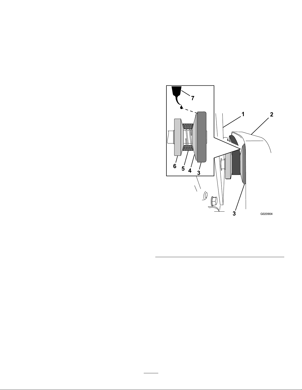
LubricatingtheClutch
ServiceInterval:Monthly
1.Fromthebackofthemachine,locatetheclutchcover
thatisbetweentheliftingbracketandthebelt(Figure
32).
Figure32
1.Liftingbracket
2.Beltguard6.Fixedcone
3.Clutchcover7.SAE5W-30oil
4.Slidingcone
2.Apply2or3dropsofSAE5W-30oilbetweenthe
clutchcoverandtheslidingcone(Figure32).
5.Belt
23
Page 24
BeltMaintenance
1
2
3
G020992
G020916
1
2
3
6
4
5
G020917
4
5
3
2
1
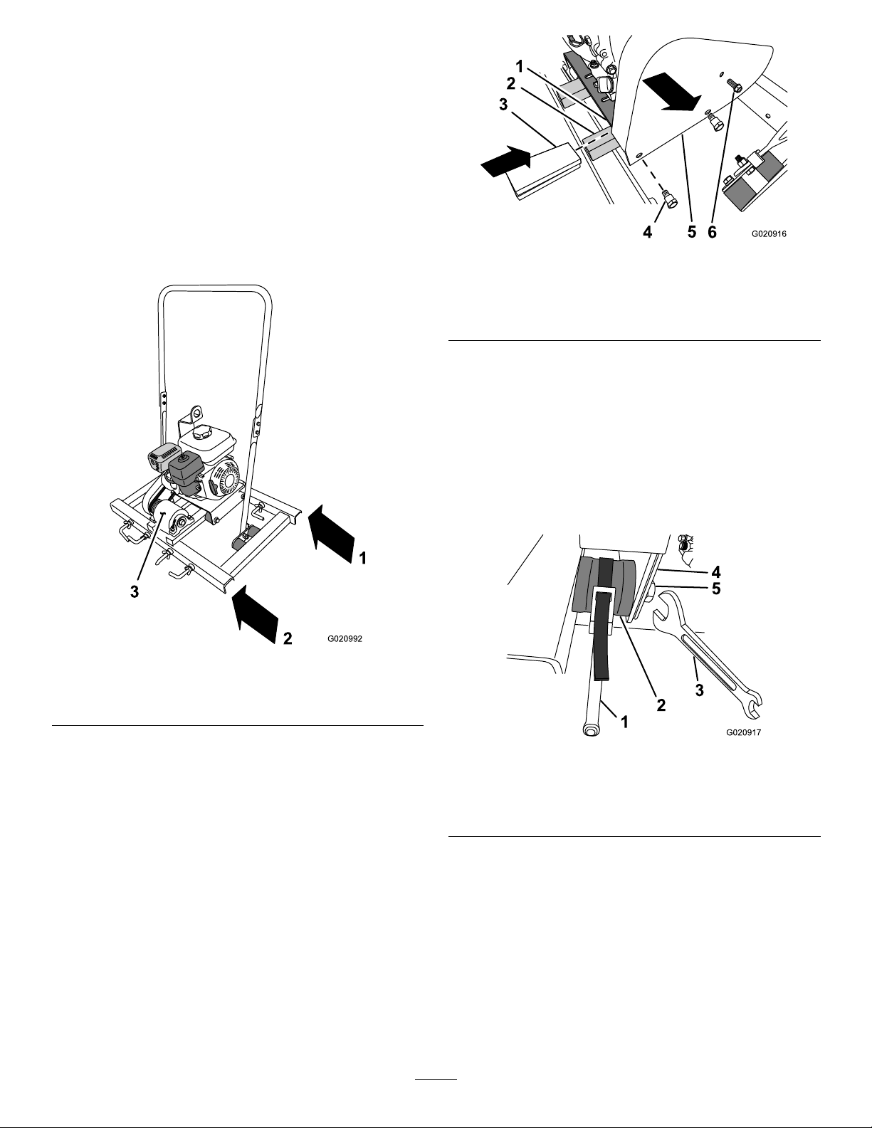
RemovingandInstallingthe BeltGuard
RemovingtheBeltGuard
1.Atthebackofthemachine,locatetheright-cross
channeloftheframe(Figure33andFigure34).
Note:Thebackofthemachineisonthesideopposite
fromtheeccentricguard.
Figure33
Figure34
1.Enginedeck
2.Right-crosschannel5.Beltguard
3.Spacer6.Bolt(1/4inch)
4.Shoulderbolt(3/8inch)
Note:Thespacerwillsupporttheenginewhenthe2
bolts(3/8inch)areremoved.
3.Removethebolt(1/4inch)fromthebeltguard(Figure
34).
4.Removethe2shoulderbolts(3/8inch)fromthebelt
guard,andremovethebeltguard(Figure34).
Note:Useastrapwrenchtokeeptheisolatorfrom
rotatingwhenremovingthe3/8inchbolt(Figure35).
1.Backofthemachine
2.Frontofthemachine
2.Inserta32to38mm(1-1/4to1-1/2inch)spacer
betweentheright-crosschannelandtheengineplate
(Figure34).
3.Eccentricguard
Figure35
1.Strapwrench
2.Isolator
3.Wrench
4.Beltguard
5.Bolt(3/8inch)
24
Page 25

InstallingtheBeltGuard
G020922
1
2
3
1
2
G020942
1.Alignthebeltguardoverthepulleys.
2.Applymediumstrength(serviceremovablethread
lockingcompoundtothethreadsofthebolt(1/4inch
and2shoulderbolts(3/8inch).
3.Alignthe(1/4inch)holeinthebeltguardwiththehole
inthebeltguardbracket(Figure34andFigure36).
4.Threadthebolt(1/4inch)throughthebeltguardand
intothebelt-guardbracket(Figure34andFigure36).
Note:Donottightenthe1/4inchbolt.
5.Aligntheholes(3/8inch)inthebeltguardwiththe
threadsintheisolators(Figure34andFigure35).
6.Securebeltguardtotheisolatorswiththe2shoulder
bolts(3/8inch)(Figure34).
Note:Useastrapwrenchkeeptheisolatorfrom
rotatingwhentighteningthe3/8inchbolt(Figure35).
7.Tightenthe1/4inchbolt.
8.Removethespacersthatarebetweentheright-cross
channelandtheengineplate(Figure34).
Figure36
ServicingtheBelt
ServiceInterval:Aftertherst25hours—Inspectand
adjustthebelt.
Monthly—Inspectandadjustthebelt.
InspectingtheBelt
1.Removethebeltguard;refertoRemovingtheBelt
Guard(page24).
2.Examinethebeltforwearordamage.Ifthebeltsare
wornordamaged,replacethebelts;refertoInspecting
theBelt(page25).
3.Examinethepulleysforwear,damageand
misalignment.
4.Lubricatetheclutch;refertoLubricatingtheClutch
(page23).
5.Installthebeltguard;refertoInstallingtheBeltGuard
(page25).
ReplacingtheBelt
RemovingtheBelt
1.Eccentricpulley3.Belt-guardbracket
2.Belt
3.Slipthebeltofftheclutchandremovefromthe
machine(Figure37).
Figure37
1.Belt
2.Clutch
1.Removethebeltguard;refertoRemovingtheBelt
Guard(page24).
2.Liftthebeltupandovertheshoulderoftheeccentric
pulley(Figure36).
Note:Rotatetheeccentricpulleybyhandtohelp
removethebelt.
25
Page 26

InstallingtheBelt
G020967
1
2
3
4
213 1
1 2 13
G020966
4
1.Alignthebeltovertheclutch(Figure37).
2.Pullthebelttowardtheeccentricpulley(Figure36).
3.Slipthebeltovertheshoulderoftheeccentricpulley
(Figure36).
Note:Rotatetheeccentricpulleybyhandtohelp
installthebelt.
AdjustingtheBelt
1.Attheclutch,alignthebeltagainstthexedcone.
Note:Useaatbladedscrewdrivertopositionthe
beltagainstthexedcone.
Figure39
1.Bolt3.Enginedeck
2.Nut4.Eccentricpulley
4.Adjustthegapbetweenthebeltandtheclutchas
follows:
•Movetheengineawayfromtheeccentricpulleyto
reducethegapbetweenthebeltandthesliding
cone(Figure39).
•Movetheenginetowardfromtheeccentricpulley
toincreasethegapbetweenthebeltandthe
slidingcone(Figure39).
5.Whenthegapmeasurementiswithinthe0.76to1.27
mm(0.03to0.05inch)range(Figure38),tightenthe
boltsandnutsthatsecuretheenginetotheenginedeck
to18N-m(13lb-ft).
6.Installthebeltguard;refertoInstallingtheBeltGuard
(page25).
Figure38
1.Fixedcone
2.Belt
2.Measurethegapbetweenthebeltandtheslidingcone
3.0.76to1.27mm(0.03to
0.05inch)gap
4.Slidingcone
(Figure38).Ifthegapis0.76to1.27mm(0.03to0.05
inch),skiptostep6.
3.Loosentheboltsandnutsthatsecuretheenginetothe
enginedeck(Figure39).
26
Page 27

Cleaning
CleaningtheMachine
Regularcleaningandwashingwillincreasethelifespanof
themachine.Cleanthemachineaftereachuse,beforethe
cementdries.
Ensurethatthefueltankcapandoilcap/dipstickaresecure
toavoidgettingwaterinthetank.
Usecarewhenusingahigh-pressuresprayer,becauseitcan
damagewarningdecals,instructionsigns,andtheengine.
Important:Lubricatetheeccentricbearingsafter
cleaning;refertoLubrication(page18).
Storage
Important:Youcanwashthemachinewithmild
detergentandwater.Donotpressurewashtheengine
oreccentricbearings.
1.Removeconcrete,sand,andaggregatefromthe
externalpartsofthemachine,especiallytheengine.
Cleandirtfromtheoutsideoftheengine'scylinder
headnsandhousing.
2.Servicetheaircleaner;refertoServicingtheAir
Cleaner(page19).
3.Greasethemachine;refertoGreasingtheMachine
(page18).
4.Lubricatetheclutch;refertoLubricatingtheClutch
(page23).
5.Changetheengineoil;refertoChangingtheEngine
Oil(page20).
6.Removethesparkplugandchecktheconditionof
each;refertoServicingtheSparkPlug(page21).
7.Forstorageover30days,conditionthefuelsystemas
follows:
Important:Donotuseanalcohol-basedstabilizer
(ethanolormethanol).
Note:Afuelstabilizer/conditionerismosteffective
whenmixedwithfreshfuelandusedatalltimes.
Donotstorestabilizerconditionedfuelforover90
days.
A.Addapetroleumbasedstabilizer/conditionerto
fuelinthetank.Followmixinginstructionsfrom
stabilizermanufacturer.
B.Starttheengineandrunituntilitstops.
C.Choketheengine.
D.Startandruntheengineuntilitwillnotstartagain.
E.Disposeoffuelproperly .Recycleasperlocal
codes.
8.Forstorageover90days,conditiontheengineas
follows:
A.Removethespark-plugwirefromthesparkplug
B.Removethesparkplugfromtheengineandpour
twotablespoonsofengineoilintothesparkplug
hole.
C.Placeragsoverthesparkplugholetocatchany
oilsprayandthenpulltherecoil-starthandleto
distributetheoilinsidethecylinder.
D.Installthesparkplug,butdonotinstallthe
spark-plugwire.
9.Checkandtightenallbolts,nuts,andscrews.Repairor
replaceanypartthatisdamagedordefective.
10.Paintallscratchedorbaremetalsurfaces.Paintis
availablefromyourAuthorizedServiceDealer.
27
Page 28

11.Storethemachineunitinaclean,drygarageorstorage
area.
12.Coverthemachinetoprotectitandkeepitclean.
28
Page 29

Troubleshooting
Problem
Theenginewillnotstart.
Theenginelackspowerorrunsrough.
PossibleCauseCorrectiveAction
1.Thefuel-valveleverisintheOff
position.
2.Thechokeisclosed.
3.Thechokeisopen.
4.TheengineOn/OffswitchisintheOff
position.
5.Theengineoillevelislow(engines
withtheoil-levelswitch).
6.Thefueltankisempty.6.Fillthefueltankwithfreshfuel.
7.Theenginecontainsbad/oldfuel.7.Drainthefueltankandcarburetor.
8.Thesparkplugisfouledorimproperly
gapped.
9.Thesparkplugiswetwithfuel(ooded
engine).
10.Thespark-plugwireislooseor
disconnected.
1.Theairlterisrestricted.1.Cleanorreplacetheairlter
2.Theenginecontainsbad/oldfuel.2.Drainthefueltankandcarburetor.
3.Thereiswaterorcontaminationinthe
fuel.
4.Thefuellineisrestricted.4.Cleanthefuellterandsedimentcup.
5.Thechokeisclosed
6.Thesparkplugiswornorhasbuildup
ontheelectrodes.
7.Thereistoomuchoilintheengine
crankcase.
1.Movethefuel-valvelevertotheOn
position.
2.Openthechokewhenstartingahot
engine.
3.Closethechokewhenstartingacold
engine.
4.RotatetheswitchtotheOnposition.
5.Filltheengine,withtherecommended
oil,totheproperlevel.
Fuelthemachinewithfreshgasoline.
8.Gaporreplacethesparkplug.
9.Removethesparkplug,dryit,and
installtheplug.Starttheenginewith
thethrottleintheMaxposition.
10.Removethespark-plugwire,cleanthe
spark-plugterminalandtheterminal
socketinthebootofthespark-plug
wire,andreinstallthespark-plugwire.
element(s).
Refuelwithfreshgasoline.
3.Drainthefueltankandcarburetor.
Fuelthemachinewithfreshgasoline.
5.Openthechoke.
6.Checktheelectrodegapandadjustor
replacethesparkplug.
7.Draintheoiltotheproperlevel.
Thebeltslipsorcomesoffthepulleys.
Theeccentricrotateswhenthethrottleof
theengineisintheidleposition.
throttleoftheengineisintherunposition.
throttleoftheengineisintherunposition.
1.Thebelttensionisinsufcient.
2.Thebeltisworn.2.Replacethebelt.
3.Theeccentricpulleyorclutchisworn.
4.Theeccentricpulleyismisalignedto
theclutch.
1.Thebelttensionisnotadjusted
correctly.
1.Thebelttensionisnotadjusted
correctly.
2.Theclutchisstuck.
1.Thebeltisworn.1.Replacethebelt. Theeccentricrotateslowlywhenthe
2.Thebelttensionisnotadjusted
correctly.
1.Adjustthebelttension.
3.ContactyourAuthorizedService
Dealer.
4.Alignthepulleytotheclutch.
1.Adjustthebelttension.
1.Adjustthebelttension. Theeccentricdonotrotatewhenthe
2.ContactyourAuthorizedService
Dealer.
2.Adjustthebelttension.
29
Page 30

Notes:
30
Page 31

Notes:
31
Page 32

Alimitedwarranty(seewarrantyperiodsbelow)
TheToroWarranty
Concrete,
Masonry,and
Compaction
Equipment
ConditionsandProductsCovered
TheT oroCompanyanditsafliate,T oroWarrantyCompany,pursuantto
anagreementbetweenthem,jointlywarrantyourT oroConcrete,Masonry ,
andCompactionEquipmentProductslistedbelowtobefreefromdefectsin
materialsorworkmanship.
Thiswarrantycoversthecostofpartsandlabor,butyoumustpay
transportationcosts.
Thefollowingtimeperiodsapplyfromthedateofpurchase:
ProductsWarrantyPeriod
ConcreteMixers
•SpindleBearingsLifetime*(originalowneronly)
MortarMixers1year
•DrumBearingsandSealsLifetime*(originalowneronly)
ForwardPlateCompactors
ReversiblePlates1year
RammerCompactors
MudBuggy1year
VibratingTrenchRoller2years
ConcreteSaws
MasonrySaws
PowerTrowels1year
Screeds
ConcreteVibrators
Whereawarrantableconditionexists,wewillrepairtheProductatnocost
toyouincludingdiagnosis,labor,andparts.
*
LifetimeWarranty-Ifthebearing(s)orseal(s)onyourmixerfail,itwillbereplacedunderwarranty ,
atnocostforpartsorlabor.
1year
2years
2years
1year
1year
1year
1year
InstructionsforObtainingWarrantyService
IfyouthinkthatyourT oroProductcontainsadefectinmaterialsor
workmanship,followthisprocedure
1.ContactanyAuthorizedServicingOutlettoarrangeserviceattheir
dealership.T olocateoneconvenienttoyou,accessourwebsiteat
www.T oro.com.Select“WheretoBuy”andselect“Contractor”under
producttype.Y oumayalsocallourtollfreenumberbelow .
2.Bringtheproductandyourproofofpurchase(salesreceipt)tothem.
3.IfforanyreasonyouaredissatisedwiththeServiceOutlet’sanalysis
orwiththeassistanceprovided,contactusat:
SWSCustomerCareDepartment
ToroWarrantyCompany
811 1LyndaleAvenueSouth
Bloomington,MN55420-1196
TollFree:800-888-9926
**
ToroAuthorizedRentalCustomerswhohavepurchasedproductsdirectlyfromT oroandhave
signedtheT oroRentalCustomerAgreementhavetheabilitytoperformtheirownwarrantywork.
PleasevisitT oro’sRentalPortalforelectronicwarrantyclamlingproceduresorcallthetollfree
numberabove.
**
:
OwnerResponsibilities
YoumustmaintainyourToroProductbyfollowingthemaintenance
proceduresdescribedintheOperator’sManual.Suchroutinemaintenance,
whetherperformedbyadealerorbyyou,isatyourexpense.Parts
scheduledforreplacementasrequiredmaintenance(“MaintenanceParts”),
arewarrantedfortheperiodoftimeuptothescheduledreplacementtime
forthatpart.Failuretoperformrequiredmaintenanceandadjustmentscan
begroundsfordisallowingawarrantyclaim.
ItemsandConditionsNotCovered
Notallproductfailuresormalfunctionsthatoccurduringthewarrantyperiod
aredefectsinmaterialsorworkmanship.Thisexpresswarrantydoesnot
coverthefollowing:
•Productfailureswhichresultfromtheuseofnon-T ororeplacement
parts,orfrominstallationanduseofadd-on,modied,orunapproved
accessories
•Productfailureswhichresultfromfailuretoperformrequired
maintenanceand/oradjustments
•ProductfailureswhichresultfromoperatingtheProductinanabusive,
negligentorrecklessmanner
•Partssubjecttoconsumptionthroughuseunlessfoundtobedefective.
Examplesofpartswhichareconsumed,orusedup,duringnormal
productoperationinclude,butarenotlimitedto,belts,wipers,spark
plugs,tires,lters,gaskets,wearplates,seals,O-rings,drivechains,
clutches.
•Failurescausedbyoutsideinuence.Itemsconsideredtobeoutside
inuenceinclude,butarenotlimitedto,weather,storagepractices,
contamination,useofunapprovedcoolants,lubricants,additives,or
chemicals,etc.
•Normal“wearandtear”items.Normal“wearandtear”includes,butis
notlimitedto,wornpaintedsurfaces,scratcheddecals,etc.
•Repairsnecessaryduetofailuretofollowrecommendedfuel
procedure(consultOperator'sManualformoredetails)
–Removingcontaminantsfromthefuelsystemisnotcovered
–Useofoldfuel(morethanonemonthold)orfuelwhichcontains
morethan10%ethanolormorethat15%MTBE
–Failuretodrainthefuelsystempriortoanyperiodofnon-use
overonemonth
•Anycomponentcoveredbyaseparatemanufacturer’swarranty
•Pickupanddeliverycharges
GeneralConditions
RepairbyanAuthorizedServicingOutletorSelf-ServiceasanAuthorized
RentalCustomerisyoursoleremedyunderthewarranty.
NeitherTheToroCompanynorToroWarrantyCompanyisliablefor
indirect,incidentalorconsequentialdamagesinconnectionwiththe
useoftheToroProductscoveredbythiswarranty,includingany
costorexpenseofprovidingsubstituteequipmentorserviceduring
reasonableperiodsofmalfunctionornon-usependingcompletionof
repairsunderthiswarranty .Allimpliedwarrantiesofmerchantability
andtnessforusearelimitedtothedurationofthisexpresswarranty.
Somestatesdonotallowexclusionsofincidentalorconsequential
damages,orlimitationsonhowlonganimpliedwarrantylasts,sothe
aboveexclusionsandlimitationsmaynotapplytoyou.
Thiswarrantygivesyouspeciclegalrights,andyoumayalsohaveother
rightswhichvaryfromstatetostate.
ExceptfortheenginewarrantycoverageandtheEmissionswarranty
referencedbelow,ifapplicable,thereisnootherexpresswarranty .The
EmissionsControlSystemonyourProductmaybecoveredbyaseparate
warrantymeetingrequirementsestablishedbytheU.S.Environmental
ProtectionAgency(EPA)ortheCaliforniaAirResourcesBoard(CARB).
RefertotheCaliforniaEmissionControlWarrantyStatementsuppliedwith
yourProductorcontainedintheenginemanufacturer’sdocumentationfor
details.
CountriesOtherthantheUnitedStatesorCanada
CustomerswhohavepurchasedT oroproductsoutsidetheUnitedStatesorCanadashouldcontacttheirT oroDistributor(Dealer)toobtainguarantee
policiesforyourcountry,province,orstate.IfforanyreasonyouaredissatisedwithyourDistributor'sserviceorhavedifcultyobtainingguarantee
information,contacttheT oroimporter.Ifallotherremediesfail,youmaycontactusatT oroWarrantyCompany.
AustralianConsumerLaw:AustraliancustomerswillnddetailsrelatingtotheAustralianConsumerLaweitherinsidetheboxoratyourlocalT oro
Dealer.
374-0288RevC
 Loading...