

Page 1

FormNo.3421-193RevB
PT-36PowerTrowel
ModelNo.68048—SerialNo.402000000andUp
ModelNo.68049—SerialNo.402000000andUp
ModelNo.68050—SerialNo.402000000andUp
ModelNo.68051—SerialNo.402000000andUp
Registeratwww.T oro.com.
OriginalInstructions(EN)
*3421-193*B
Page 2
WARNING
Introduction
CALIFORNIA
Proposition65Warning
Thisproductcontainsachemical
orchemicalsknowntotheStateof
Californiatocausecancer,birthdefects,
orreproductiveharm.
Theengineexhaustfromthisproduct
containschemicalsknowntotheStateof
Californiatocausecancer,birthdefects,
orotherreproductiveharm.
Useofthisproductmaycauseexposure
tochemicalsknowntotheStateof
Californiatocausecancer,birthdefects,
orotherreproductiveharm.
ItisaviolationofCaliforniaPublicResourceCode
Section4442touseoroperatetheengineonany
forest-covered,brush-covered,orgrass-covered
landwithoutasparkarrestermufermaintainedin
workingorder,ortheengineconstricted,equipped,
andmaintainedforthepreventionofre.Otherstates
orfederalareasmayhavesimilarlaws.GenuineT oro
sparkarrestersareapprovedbytheUSDAForestry
Service.
Thismachineisusedtocreateasmoothnishto
concreteslabs.
Readthisinformationcarefullytolearnhowtooperate
andmaintainyourproductproperlyandtoavoid
injuryandproductdamage.Youareresponsiblefor
operatingtheproductproperlyandsafely .
YoumaycontactT orodirectlyatwww.Toro.comfor
productandaccessoryinformation,helpndinga
dealer,ortoregisteryourproduct.
Wheneveryouneedservice,genuineToroparts,or
additionalinformation,contactanAuthorizedService
DealerorToroCustomerServiceandhavethemodel
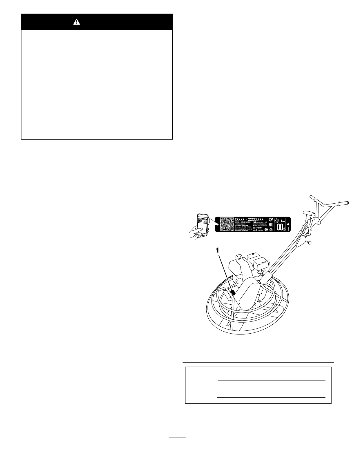
andserialnumbersofyourproductready.Figure
1illustratesthelocationofthemodelandserial
numbersontheproduct.Writethenumbersinthe
spaceprovided.
Important:Withyourmobiledevice,youcan
scantheQRcodeontheserialnumberdecal(if
equipped)toaccesswarranty,parts,andother
productinformation.
Becauseinsomeareastherearelocal,state,or
federalregulationsrequiringthatasparkarresterbe
usedontheengineofthismachine,asparkarresteris
availableasanoption.Ifyourequireasparkarrester,
contactyourAuthorizedServiceDealer.
Theenclosedengineowner'smanualissupplied
forinformationregardingtheUSEnvironmental
ProtectionAgency(EPA)andtheCaliforniaEmission
ControlRegulationofemissionsystems,maintenance,
andwarranty.Replacementsmaybeorderedthrough
theenginemanufacturer.
g239848
Figure1
1.Locationofthemodelandserialnumbers
ModelNo.
©2017—TheToro®Company
8111LyndaleAvenueSouth
Bloomington,MN55420
SerialNo.
Contactusatwww.Toro.com.
2
PrintedintheUSA
AllRightsReserved
Page 3

Thismanualidentiespotentialhazardsandhas
safetymessagesidentiedbythesafetyalertsymbol
(Figure2),whichsignalsahazardthatmaycause
seriousinjuryordeathifyoudonotfollowthe
recommendedprecautions.
Figure2
1.Safety-alertsymbol
Thismanualuses2wordstohighlightinformation.
Importantcallsattentiontospecialmechanical
informationandNoteemphasizesgeneralinformation
worthyofspecialattention.
Contents
Safety.......................................................................4
SafeOperatingPractices....................................4
SafetyandInstructionalDecals..........................6
ProductOverview.....................................................7
Controls.............................................................7
g000502
Specications....................................................9
Attachments/Accessories...................................9
Operation..................................................................9
CheckingtheEngine-OilLevel............................9
CheckingtheGearcaseOilLevel......................10
CleaningDebrisfromtheMachine....................10
FoldingandUnfoldingtheHandle.....................10
AddingFuel.......................................................11
StartingtheEngine...........................................13
ShuttingOfftheEngine.....................................13
OperatingtheMachine.....................................13
Maintenance...........................................................14
RecommendedMaintenanceSchedule(s)...........14
Pre-MaintenanceProcedures..............................14
DisconnectingtheSpark-PlugWire..................14
Lubrication..........................................................15
LubricatingtheBladeArms...............................15
EngineMaintenance...........................................15
ServicingtheAirCleaner..................................15
ServicingtheEngineOil....................................16
ServicingtheGearcaseOil...............................17
ServicingtheSparkPlug...................................18
BeltMaintenance................................................19
CheckingtheBelt,PulleyAlignment,Belt
Tension,andBelt-GuideGap........................19
RemovingtheBeltGuard..................................19
InstallingtheBeltGuard....................................19
RemovingtheBelt............................................20
InstallingtheBelt..............................................20
AligningthePulleys..........................................20
AdjustingtheDyna-Clutch................................20
AdjustingtheBeltGuide...................................21
ControlsSystemMaintenance.............................22
AdjustingtheTiltKnob......................................22
AdjustingtheProPitchLinkageRod..................22
TestingtheDyna-ClutchLever..........................23
AdjustingtheBlades.........................................23
AdjustingtheBladeArms..................................25
Storage...................................................................25
Troubleshooting......................................................26
3
Page 4

Safety
–Extinguishallcigarettes,cigars,pipes,and
othersourcesofignition.
Improperuseormaintenancebytheoperatororowner
canresultininjury.Toreducethepotentialforinjury,
complywiththesesafetyinstructionsandalwayspay
attentiontothesafetyalertsymbol,whichmeans
Caution,Warning,orDanger—personalsafety
instruction.Failuretocomplywiththeinstructionmay
resultinpersonalinjuryordeath.
SafeOperatingPractices
Thisproductiscapableofcausingseriousinjury .
Alwaysfollowallsafetyinstructionstoavoidserious
injuryordeath.
WARNING
Engineexhaustcontainscarbonmonoxide,
anodorless,deadlypoisonthatcankillyou.
Donotruntheengineindoorsorinan
enclosedarea.
Training
•ReadtheOperator'sManualandothertraining
material.Iftheoperator(s)ormechanic(s)cannot
readorunderstandtheinformation,itisthe
owner'sresponsibilitytoexplainthismaterialto
them.
•Becomefamiliarwiththesafeoperationofthe
equipment,operatorcontrols,andsafetysigns.
•Alloperatorsandmechanicsshouldbetrained.
Theownerisresponsiblefortrainingtheusers.
•Neverletchildrenoruntrainedpeopleoperateor
servicetheequipment.Localregulationsmay
restricttheageoftheoperator.
•Theowner/usercanpreventandisresponsiblefor
accidentsorinjuriesoccurringpeopleordamage
toproperty.
–Useonlyanapprovedcontainer
–Donotremovethefuelcaporllthefueltank
whiletheengineisrunningorhot.
–Donotaddordrainfuelinanenclosedspace.
–Donotstorethemachineorfuelcontainer
wherethereisanopename,spark,orpilot
light,suchasonawaterheaterorother
appliance.
–Ifyouspillfuel,donotattempttostartthe
engine;avoidcreatinganysourceofignition
untilthefuelvaporshavedissipated.
•Checkthattheshieldsareattachedand
functioningproperly.Donotoperateunlessthey
arefunctioningproperly.
Operation
•Useyourfullattentionwhileoperatingthe
machine.Donotengageinanyactivitythat
causesdistractions;otherwise,injuryorproperty
damagemayoccur.
•Neverrunanengineinanenclosedorpoorly
ventilatedarea.
•Operatethemachineonlyingoodlight,keeping
awayfromholesandhiddenhazards.
•Stoponlevelground,setthethrottletoslow,and
shutofftheenginebeforeleavingtheoperator's
positionforanyreason.
•Ensurethattheareaisclearofotherpeoplebefore
operatingthemachine.Shutoffthemachineif
anyoneentersthearea.
•Keepbystandersoutoftheoperatingarea.Stop
themachineifanyoneentersthearea.
•Keepyourfeetclearoftheplatecompactor.
•Donotoperatethemachinewhileill,tired,or
undertheinuenceofalcoholordrugs.
Preparation
•Wearappropriateclothingincludinghardhat,eye
protection,longpants,substantial,slip-resistant
footwear,andhearingprotection.Tiebacklong
hair,securelooseclothing,anddonotwearloose
jewelry.
•Inspecttheareawheretheequipmentistobe
usedandensurethatallobjectsareremovedfrom
theareabeforeuse.
•Useextracarewhenhandlingfuel.Theyare
ammableandvaporsareexplosive.
•Donotchangetheenginegovernorsettingor
overspeedtheengine.
•Usecarewhenloadingorunloadingthemachine
intoatrailerortruck.
•Donottouchpartswhichmaybehotfrom
operation.Allowthemtocoolbeforeattemptingto
maintain,adjust,orservice.
•Lightningcancausesevereinjuryordeath.If
lightningisseenorthunderisheardinthearea,do
notoperatethemachine;seekshelter.
4
Page 5

MaintenanceandStorage
•Lettheenginecoolbeforestoringanddonotstore
themachinenearanopename.
•Positionthemachineonalevelsurface,setthe
throttletoslow,andshutofftheengine.Waitfor
allmovementtostopbeforeadjusting,cleaning,
orrepairing.
•Cleandebrisfromdrives,mufers,andtheengine
tohelppreventres.Cleanupoilorfuelspills.
•Donotstorefuelnearamesordrainindoors.
•Neverallowuntrainedpersonneltoservicethe
machine.
•Carefullyreleasepressurefromcomponentswith
storedenergy.
•Disconnectthesparkplugbeforemakingany
repairs.
•Keephandsandfeetawayfrommovingparts.If
possible,donotmakeadjustmentswiththeengine
running.
•Keepallpartsingoodworkingconditionandall
hardwaretightened.Replaceallwornordamaged
decals.
•Keepnutsandboltstight.Keepequipmentin
goodcondition.
•Stopandinspecttheequipmentifyoustrike
anobject.Makeanynecessaryrepairsbefore
restarting.
•UseonlygenuineT ororeplacementpartsto
ensurethatoriginalstandardsaremaintained.
5
Page 6

SafetyandInstructionalDecals
Safetydecalsandinstructionsareeasilyvisibletotheoperatorandarelocatednearanyarea
ofpotentialdanger.Replaceanydecalthatisdamagedormissing.
93-9084
decal93-9084
1.Liftpoint
2.Tie-downpoint
117–4979
1.Entanglementhazard,belt—keepawayfrommovingparts;
keepallguardsandshieldsinplace
125–4933
1.Warning—readthe
Operator’sManual.
2.Warning—wearhearing
protection.
3.Warning—keep
bystandersawayfrom
themachine.
4.Chokinghazard—donot
runtheengineinan
unventilatedarea.
5.Explosionhazard—shut
offtheengineand
extinguishallames
beforerefueling.
decal125-4934
125–4934
1.ReadtheOperator’s
Manual.
2.Disengageclutch
decal117-4979
3.Engageclutch
decal125-4935
125–4935
Models68049and68051only
decal125-4933
1.Lowertheblades2.Raisetheblades
decal133-5619
133-5619
6
Page 7
ProductOverview
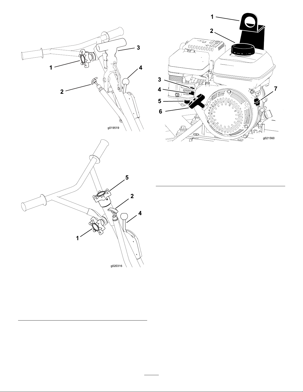
g019519
g021560
Figure4
1.Liftingpoint5.Sedimentcup
2.Fuel-tankcap6.Recoil-starterhandle
3.Chokelever7.EngineOn/Offswitch
4.Fuelvalve
Figure3
1.Handle-adjustmentknob
2.Throttlehandle5.Tilt-adjustmentknob
3.ProPitchhandle(Models
68049and68051only)
4.Dyna-Clutchlever
(Models68048and68050
only)
Controls
Recoil-StarterHandle
Pulltherecoil-starterhandletostarttheengine
(Figure4).
FuelValve
Closethefuelvalvewhentransportingorstoringthe
g020316
machine(Figure4).
ChokeLever
Usethechokelever(Figure4)tostartacoldengine.
Beforepullingtherecoil-starterhandle,movethe
chokelevertotheclosedposition.Oncetheengineis
running,movethechokelevertotheopenposition.
Note:Awarmenginerequireslittleornochoking.
EngineOn/OffSwitch
TheOn/Offswitch(Figure4)allowstheoperatorof
themachinetostartandshutofftheengine.This
switchislocatedonthefrontoftheengine.Rotatethe
On/OffswitchtotheOnpositiontostartandrunthe
7
Page 8

engine.RotatetheOn/OffswitchtotheOffpositionto
shutofftheengine.
ThrottleHandle
Pullthethrottlehandle(Figure3)toincreasethe
enginespeed,andpushthehandletodecreasethe
enginespeed.Turnthehandleclockwisetolock
thethrottleataspecicspeed.Turnthehandle
counterclockwisetounlockthethrottle.
Handle-AdjustmentKnob
Turntheknobcounterclockwisetoloosenandmove
thehandletothedesiredposition.Turntheknob
clockwisetotightenandlockthehandleinplace
(Figure3).
Dyna-ClutchLever
MovetheDyna-Clutchlever(Figure5)totheOn
position(up)toallowthebladestorotate.Movethe
levertotheOffposition(down)tostoptheblades.In
theeventthatyoureleasethehandlewhiletheblades
areturning,thecentrifugalforcefromtheswingofthe
handlewillthrowtheclutchlevertotheStopposition.
g019367
Figure6
1.Tripbutton2.Handle
Tilt-AdjustmentKnob
Models68048and68050Only
Turntheknobclockwisetoincreasetheangleofthe
blades(Figure6).Turntheknobcounterclockwiseto
attenordecreasetheangleoftheblades.
Figure5
1.Dyna-Clutchlever
ProPitch
Models68049and68051Only
Pullthehandletoincreasetheangleoftheblades
totheconcrete.Pressthetripbuttontoreleasethe
lock,andpushthehandletodecreasetheangleof
theblades.
TM
Handle
g019978
Figure7
1.Tilt-adjustmentknob
8
g021559
Page 9
Specications
Note:Specicationsanddesignaresubjectto
changewithoutnotice.
Models68048and6804968050and68051
Width
Length(operating)177cm(70inches)190.5cm(75
Height(operating)99cm(39inches)99cm(39inches)
Weight
Attachments/Accessories
Aselectionofapprovedattachmentsandaccessories
areavailableforusewiththemachinetoenhance
andexpanditscapabilities.ContactyourAuthorized
ServiceDealerorDistributororgotowww.T oro.com
foralistofallapprovedattachmentsandaccessories.
92cm(36.5inches)117cm(46inches)
102kg(225lb)112kg(245lb)
Operation
Note:Determinetheleftandrightsidesofthe
machinefromthenormaloperatingposition.
CheckingtheEngine-Oil
inches)
Level
ServiceInterval:Beforeeachuseordaily
Themachinecomesfromthefactorywithoilinthe
enginecrankcase.However,itmaybenecessaryto
addoil.Addonlyenoughoiltoraisetheleveltothe
Fullmarkonthedipstick;refertoServicingtheEngine
Oil(page16).
OilType:4-cycleengineoilthatmeetsorexceedsthe
requirementsforAPIservicecategorySJorhigher
Models
68048and68049
68050and68051
CrankcaseCapacity
0.58L(0.61USqt)
1.1L(1.2USqt)
Important:Ifyouruntheenginewhiletheoil
levelinthecrankcaseistoolowortoohigh,you
maydamagetheengine.
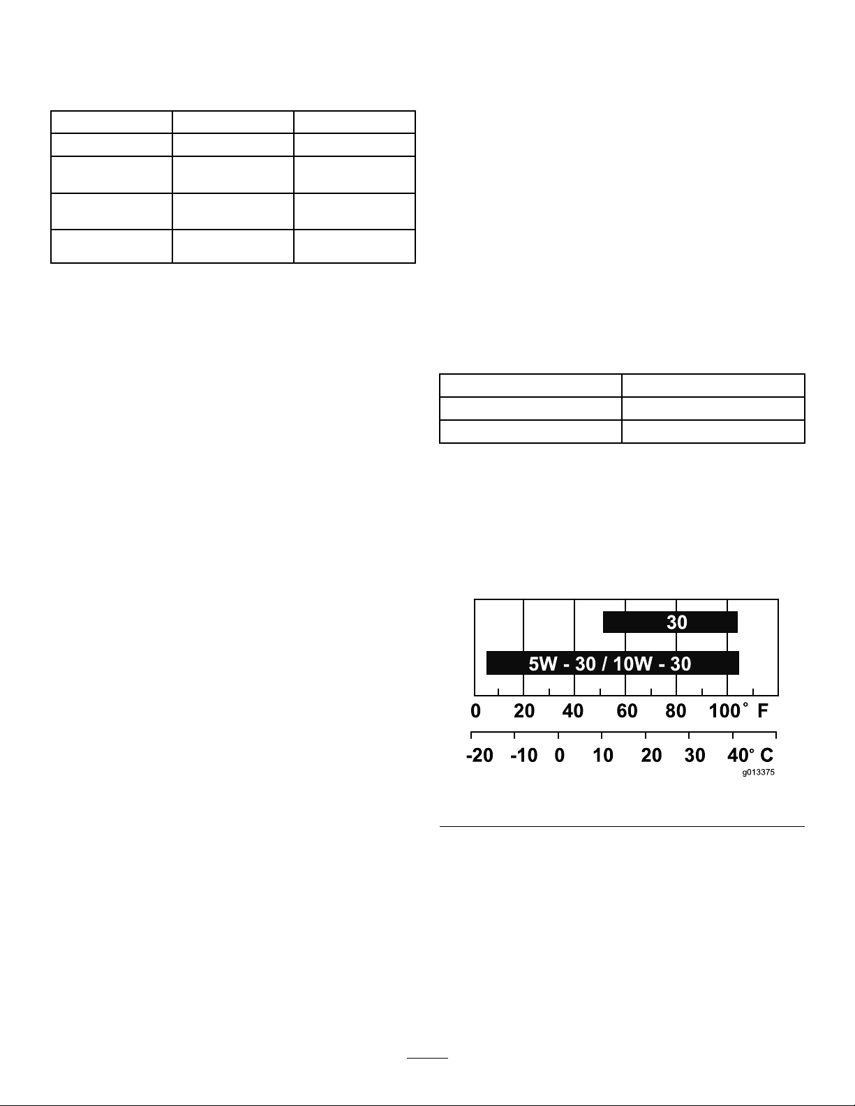
Note:UseSAE10W-30forgeneraluse.Youcan
usetheotherviscositiesshowninthechartwhen
theaveragetemperatureinyourareaiswithinthe
indicatedrange(Figure8).
Figure8
1.Positionthemachineonalevelsurface.
g013375
2.SettheDyna-ClutchlevertotheStopposition,
shutofftheengine,waitforallmovingpartsto
stop,andturnofftheengineswitch.
3.Cleanaroundthedipstick(Figure9)sothat
dirtcannotfallintothellportanddamagethe
engine.
9
Page 10

Figure9
g019746
Figure10
g021590
1.Fillport
2.Dipstick
4.Unscrewthedipstickandwipetheendclean
(Figure9).
5.Slidethedipstickfullyintothellport(Figure9)
withoutthreadingitintotheport.
6.Removethedipstickandlookattheend.Ifthe
engineoillevelislow,slowlypouronlyenough
oilintothellporttoraisetheleveltotheFull
markonthedipstick(Figure9).
7.Installandsecurethedipstick.
3.Oil-levelupperlimit
4.Oil-levellowerlimit
CheckingtheGearcaseOil Level
ServiceInterval:Beforeeachuseordaily
1.Positionthemachineonalevelsurface.
2.SettheDyna-ClutchlevertotheSTOPposition,
shutofftheengine,andwaitforallmovingparts
tostop.
3.Lookatthesightglassinthegearcaseplug
(Figure10).Theoillevelshouldbe3/4full.
Iftheoillevelisnotcorrect,refertoServicingthe
GearcaseOil(page17).
CleaningDebrisfromthe Machine
ServiceInterval:Beforeeachuseordaily
1.SettheDyna-ClutchlevertotheSTOPposition,
shutofftheengine,waitforallmovingpartsto
stop,andshutofftheengine.
2.Brushdirtanddebrisawayfromtheaircleaner
andengineopenings.
FoldingandUnfoldingthe Handle
1.Turnthehandle-adjustmentknob
counterclockwisetoloosenthehandle.
2.Placethehandletothedesiredpositionandturn
thehandle-adjustmentknobclockwisetotighten
thehandle(Figure11).
10
Page 11

Figure11
1.Handlefullyextended3.Handlefolded
2.Handle-adjustmentknob
DANGER
Incertainconditions,fuelisextremely
ammableandhighlyexplosive.Areor
explosionfromfuelcanburnyouandothers
andcandamageproperty.
•Fillthefueltankoutdoors,inanopenarea,
whentheengineiscold.Wipeupanyfuel
thatspills.
•Neverllthefueltankinsideanenclosed
trailer.
•Donotllthefueltankcompletelyfull.
Addfueltothefueltankuntilthelevelis6
g019366
to13mm(1/4to1/2inch)belowthebottom
ofthellerneck.Thisemptyspaceinthe
tankallowsfueltoexpand.
•Neversmokewhenhandlingfuel,andstay
awayfromanopenameorwherefuel
fumesmaybeignitedbyaspark.
AddingFuel
•Forbestresults,useonlyclean,fresh(lessthan
30daysold),unleadedgasolinewithanoctane
ratingof87orhigher((R+M)/2ratingmethod).
•Ethanol:Gasolinewithupto10%ethanol
(gasohol)or15%MTBE(methyltertiarybutyl
ether)byvolumeisacceptable.Ethanoland
MTBEarenotthesame.Gasolinewith15%
ethanol(E15)byvolumeisnotapprovedforuse.
Neverusegasolinethatcontainsmorethan10%
ethanolbyvolume,suchasE15(contains15%
ethanol),E20(contains20%ethanol),orE85
(containsupto85%ethanol).Usingunapproved
gasolinemaycauseperformanceproblemsand/or
enginedamagewhichmaynotbecoveredunder
warranty..
•Donotusegasolinecontainingmethanol.
•Donotstorefueleitherinthefueltankorfuel
containersoverthewinterunlessafuelstabilizer
isused.
•Donotaddoiltogasoline.
•Storefuelinanapprovedcontainerand
keepitoutofthereachofchildren.Donot
usefuelthathasbeenstoredformorethan
30days.
•Donotoperatewithoutentireexhaust
systeminplaceandinproperworking
condition.
11
Page 12

DANGER
Incertainconditionsduringfueling,static
electricitycanbereleasedcausingaspark
whichcanignitethefuelvapors.Areor
explosionfromfuelcanburnyouandothers
andcandamageproperty.
•Alwaysplacefuelcontainersontheground
awayfromyourvehiclebeforelling.
•Donotllfuelcontainersinsideavehicle
oronatruckortrailerbedbecauseinterior
carpetsorplastictruckbedlinersmay
insulatethecontainerandslowthelossof
anystaticcharge.
•Whenpractical,removefuel-powered
equipmentfromthetruckortrailerand
refueltheequipmentwithitswheelsonthe
ground.
•Ifthisisnotpossible,thenrefuelsuch
equipmentonatruckortrailerfroma
portablecontainerratherthanfromafuel
dispensernozzle.
•Ifafuel-dispensernozzlemustbeused,
keepthenozzleincontactwiththerimof
thefueltankorcontaineropeningatall
timesuntilfuelingiscomplete.
UsingFuelStabilizer/Conditioner
Useafuelstabilizer/conditionerinthemachineto
keepthefuelfreshduringstorageof90daysorless.
Ifyouarestoringthemachineforlonger,drainthefuel
tank;refertoStorage(page25).
Important:Donotusefueladditivescontaining
methanolorethanol.
Addthecorrectamountoffuelstabilizer/conditionerto
thefuel,andfollowthedirectionsofthemanufacturer.
Note:Fuelstabilizer/conditionerismosteffective
whenmixedwithfreshfuel.Tominimizethechanceof
varnishdepositsinthefuelsystem,usefuelstabilizer
atalltimes.
12
Page 13

FillingtheFuelTank
Models
68048and68049
68050and68051
1.SettheDyna-ClutchlevertotheSTOPposition,
shutofftheengine,waitforallmovingpartsto
stop,andturnofftheengineswitch.
2.Allowtheenginetocool.
3.Cleanaroundthefuel-tankcapandremoveit
(Figure12).
Note:Thecapistetheredtothefueltank.
FuelTankCapacity
3.1L(0.82USgallons)
5.3L(1.40USgallons)
StartingtheEngine
1.Setthethrottletofullspeedandsetthe
Dyna-ClutchlevertotheSTOPposition.
2.MovetheengineswitchtotheONpositionand
turnonthefuelvalve.
3.Movethechokelevertotheleftifyouare
startingacoldengine.
Note:Awarmorhotenginemaynotrequire
choking.
4.Pulltherecoil-starthandleslowlyuntilyoufeel
someresistance,thenpulltheitsharplytostart
theengine.
5.Aftertheenginestarts,graduallymovethe
choketotheright.Iftheenginestallsor
hesitates,movethechokeleftagainuntilthe
enginewarmsup.
6.Movethethrottlelevertodesiredsetting.
ShuttingOfftheEngine
1.Reducetheenginespeedtoidle.
2.Turntheengineswitchandfuelvalveoff.
3.Waitforallmovingpartstostopbefore
proceeding.
Figure12
1.Maximumfuellevel
4.Addunleadedfueltothefueltankuntilthe
levelisatthebottomofthemaximumfuellevel
(Figure12).
Important:Theextraspaceinthetank
allowsthefueltoexpand.Donotllthefuel
tankcompletelyfull.
5.Installthefuel-tankcapsecurely.
6.Wipeupanyspilledfuel.
OperatingtheMachine
Important:Usethemachineonconcretethathas
notsetcompletely,butensurethattheconcrete
hassetenoughtosupporttheweightofthe
machine.
1.Starttheengine.
2.Aftertheenginehaswarmedup,adjustthe
throttletoapproximatelyhalfspeed.
3.Adjustthebladestothedesiredposition.
g020679
•Foroating,setthebladesat,butwith
sometensiononthecable.
•Fornishing,setthepitchofthebladesto
approximately6to9mm(1/4to3/8inches),
orapproximately5to10°.
4.Holdthehandlermlywith1hand,andmove
theDyna-ClutchlevertotheOnpositiontostart
themovementoftheblades.
5.Guidethetrowelovertheconcreteinacircular
back-and-forthmotion.
Note:Ifthebladesstarttodigintotheconcrete
decreasetheamountofthepitch.
6.SettheDyna-ClutchlevertotheOffposition,
waitforanymovingpartstostopmoving,and
shutofftheengine;refertoShuttingOffthe
Engine(page13).
13
Page 14

Maintenance
RecommendedMaintenanceSchedule(s)
MaintenanceService
Interval
Aftertherst25hours
Beforeeachuseordaily
Every40hours
Every50hours
Every100hours
Every150hours
Every200hours
Every300hours
Yearlyorbeforestorage
MaintenanceProcedure
•Changetheengineoil.
•Checktheengine-oillevel.
•Checkthegearcaseoillevel.
•Cleandebrisfromtheaircleanerandengine.
•Lubricatethebladearms.
•Inspecttheaircleanerelements.
•Checkforloosefasteners.
•Checkthebelt,pulleyalignment,belttension,andbelt-guidegap.
•Cleantheairlterelements.Cleanthemmorefrequentlyindustyoperating
conditions.
•Changetheengineoil.
•Inspectandadjustthesparkplug;replaceitifnecessary .
•Changethegearcaseoil.
•Replacethesparkplug.
•Replacethepaperaircleanerelement.Replaceitmorefrequentlyindustyoperating
conditions.
•Touchupchippedpaint
Pre-Maintenance
Procedures
Disconnectingthe Spark-PlugWire
Beforeperforminganymaintenanceontheengine,
belts,orblades,disconnectthespark-plugwirefrom
thesparkplug(Figure13).
g019430
Figure13
1.Spark-plugwire
14
Page 15

Lubrication
EngineMaintenance
LubricatingtheBladeArms
ServiceInterval:Beforeeachuseordaily
GreaseType:General-purposegrease.
1.Cleanaroundeachgreasettingwitharagand
lifttheplasticcapoffeachgreasetting.
2.Pumpseveralshotsofgreaseintoeachtting
untilitstartstooozeoutofthebearing(Figure
14andFigure15).
Important:Pumpgreaseinslowlyand
carefullytopreventdamagetothebearing
seals.
ServicingtheAirCleaner
ServiceInterval:Beforeeachuseordaily—Inspect
theaircleanerelements.
Every50hours—Cleantheairlterelements.
Cleanthemmorefrequentlyindustyoperating
conditions.
Every300hours/Y early(whichevercomes
rst)—Replacethepaperaircleanerelement.
Replaceitmorefrequentlyindustyoperating
conditions.
Important:Donotoperatetheenginewithout
theair-cleanerassembly;extremeenginedamage
willoccur.
1.SettheDyna-ClutchlevertotheSTOPposition,
shutofftheengine,andwaitforallmovingparts
tostop.
2.Disconnectthewirefromthesparkplug.
3.Removethenutthatsecurestheair-cleaner
cover(Figure16BoxA).
3.Wipeupanyexcessgrease.
g019383
Figure14
g019396
Figure15
15
Page 16
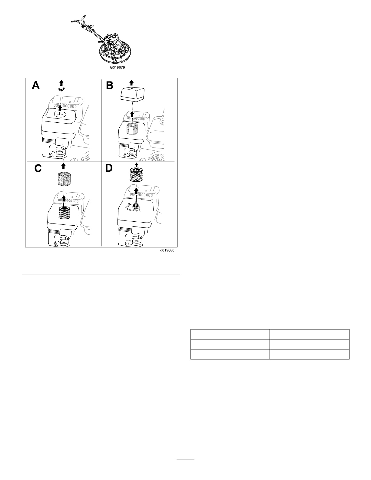
4.Removethecover(Figure16BoxB).
Note:Becarefultopreventdirtanddebrisfrom
fallingintothebase.
5.Removethefoamandpaperelementsfromthe
base(Figure16BoxC).
g019679
6.Removethefoamelementfromthepaper
element(Figure16BoxD).
7.Inspectthefoamandpaperelements,and
replacethemiftheyaredamagedorexcessively
dirty.
Note:Nevertrytobrushdirtoffthepaper
element;brushingforcesthedirtintothebers.
8.Cleanthefoamelementinwarm,soapywater
orinanonammablesolvent.
Note:Donotusefueltocleanthefoamelement
becauseitcouldcreateariskofreorexplosion.
9.Rinseanddrythefoamelementthoroughly .
10.Dipthefoamelementincleanengineoil,then
squeezeouttheexcessoil.
Note:Excessoilinthefoamelementrestricts
theairowthroughtheelementandmayreach
thepaperlterandclogit.
11.Wipedirtfromthebaseandthecoverwitha
moistrag.
Figure16
Note:Becarefultopreventdirtanddebrisfrom
g019680
enteringtheairductleadingtothecarburetor.
12.Installtheaircleanerelementsandensurethat
theyareproperlypositioned.
13.Securelyinstallthecoverwiththenut.
ServicingtheEngineOil
OilType:4-cycleengineoilthatmeetsorexceedsthe
requirementsforAPIservicecategorySJorhigher
Models
68048and68049
68050and68051
Important:Iftheoillevelinthecrankcaseistoo
lowortoohighandyouruntheengine,youmay
damagetheengine.
Viscosity:UseSAE10W-30forgeneraluse.You
canusetheotherviscositiesshowninthechartwhen
theaveragetemperatureinyourareaiswithinthe
indicatedrange(Figure8).
CrankcaseCapacity
0.58L(0.61USqt)
1.1L(1.2USqt)
16
Page 17

7.Removethedipstick(Figure9)andslowlypour
oilintothellholeuntiltheoilisbetweenthe
upperandlowerllmarksonthedipstick.
8.Installandsecurethedipstick.
9.Wipeupanyspilledoil.
ServicingtheGearcaseOil
Figure17
ChangingtheEngineOil
ServiceInterval:Aftertherst25hours
Every100hours
WARNING
Oilmaybehotaftertheenginehasbeenrun,
andcontactwithhotoilcancausesevere
personalinjury .
Avoidcontactingthehotengineoilwhenyou
drainit.
1.Positionthemachineonalevelsurface.
2.SettheDyna-ClutchlevertotheSTOPposition,
shutofftheengine,andwaitforallmovingparts
tostop.
3.Disconnectthewirefromthesparkplug.
4.Placeapanunderthedrainplugtocatchtheoil.
5.Removethedrainplug(Figure18).
g013375
ServiceInterval:Every150hours
OilType:80W-90gearoilthatmeetsorexceeds
APIservicecategoryGL-5.
Capacity:1.18L(1.25USqt)
1.SettheDyna-ClutchlevertotheSTOPposition,
shutofftheengine,andwaitforallmovingparts
tostop.
2.Disconnectthewirefromthesparkplug.
3.Placeapanunderthedrainplugtocatchtheoil.
4.Removethegearcaseplug(Figure18).
g021574
Figure19
Figure18
1.Drainplug
6.Replacetheplugwhentheoilhasdrained
completely.
Note:Disposeoftheusedoilatacertied
recyclingcenter.
1.Gearcaseplug
5.Tipthemachineanddraintheoilcompletelyout
ofthegearcase.
Note:Disposeoftheusedoilatacertied
recyclingcenter.
6.Returnthemachinetoanupright,levelposition.
g019417
7.Placea3.8cm(1-1/2inch)blockunder
thestationarybladeguard(outerring)so
thatthesideofthegearboxwiththeplugis
approximately6mm(1/4inch)higherthanthe
othersideofthegearbox.
8.Slowlypouroilintotheplugholeuntiltheoil
reachesthethreadsofthehole.
Note:Ifnecessary,useaexiblefunnel.
17
Page 18

9.Applythread-sealingcompoundtothethreads
oftheplug.
10.Installandtightenthepluguntilitissecure,and
returnthemachinetoanupright,levelposition.
Note:Theoillevelinthesightglassoftheplug
shouldbe3/4full(Figure20).
ServicingtheSparkPlug
ServiceInterval:Every100hours—Inspectand
adjustthesparkplug;replaceitif
necessary.
Every200hours—Replacethesparkplug.
UseanNGKBPR6ESsparkplugorequivalent.
1.SettheDyna-ClutchlevertotheSTOPposition,
shutofftheengine,andwaitforallmovingparts
tostop.
2.Disconnectthewirefromthesparkplug.
3.Cleanaroundthesparkplug.
4.Removethesparkplugfromthecylinderhead.
Important:Replaceacracked,fouled,or
dirtysparkplug.Donotcleantheelectrodes,
becausegritenteringthecylindercan
damagetheengine.
5.Setthegapontheplugto0.76mm(0.030inch);
refertoFigure21.
Figure20
g021590
g019300
Figure21
1.Sideelectrode
2.Centerelectrode4.0.76mm(0.030inch)gap
3.Insulator
6.Carefullyinstallthesparkplugbyhand(toavoid
crossthreading)untilitishandtight.
7.Tightenthesparkpluganadditional1/2turnif
itisnew;otherwise,tightenitanadditional1/8
to1/4turn.
Important:Aloosesparkplugcanbecome
veryhotandcandamagetheengine;
overtighteningasparkplugmaydamagethe
threadsinthecylinderhead.
8.Connectthewiretothesparkplug.
18
Page 19

BeltMaintenance
CheckingtheBelt,Pulley Alignment,BeltTension, andBelt-GuideGap
ServiceInterval:Every40hours
1.Removethebeltguard;refertoRemovingthe
BeltGuard(page19).
2.MovetheDyna-ClutchlevertotheSTOPposition.
3.Checktheconditionofthebeltforwearor
damage.
Note:Ifthebeltiswornordamaged,replace
thebelt;refertoRemovingtheBelt(page20)
andInstallingtheBelt(page20).
RemovingtheBeltGuard
1.Removethe2hex-washerheadbolts(5/16x1
inch)thatsecurethebeltguardtothebelt-guard
bracket(Figure22).
g024872
Figure22
4.MovetheDyna-ClutchlevertotheRUNposition.
5.Checkthatthebeltisalignedstraightbetween
pulleys.
Note:Ifthebeltdoesnotrunstraightbetween
pulleys,alignthepulleys;refertoAligningthe
Pulleys(page20).
6.Checkthatthebelthasenoughtensiontoatten
itbetweentheenginepulleyandthebelttension
pulley.
Note:Ifbelttensionistoolow,adjustthe
tensionofthebelt-tensionpulley;referto
AdjustingtheDyna-Clutch(page20).
7.Measurethegapbetweenthebeltandthebelt
guide.Theairgapshouldbeapproximately6
mm(1/4inch).
Note:Iftheairgapislargerorsmallerthan6
mm(1/4inch),adjustthebeltguide(Figure26);
refertoAdjustingtheBeltGuide(page21).
8.Installthebeltguard;refertoInstallingtheBelt
Guard(page19).
1.Hex-washerheadbolt3.Belt-coverbracket
2.Beltcover
2.Pullthebeltguardawayfromtheengineand
thenup(Figure22).
InstallingtheBeltGuard
1.Aligntheholesinthebeltguardwiththeholesin
thebelt-coverbracket(Figure22).
2.Securethebeltguardtothebracketwiththe2
hex-washerheadbolts(5/16x1inch).
19
Page 20
RemovingtheBelt
AligningthePulleys
1.Positionthemachineonalevelsurface,place
theDyna-ClutchleverintheSTOPposition,shut
offtheengine,anddisconnectthespark-plug
wire.
2.Removethebeltguard;refertoRemovingthe
BeltGuard(page19).
3.Slipthebeltoffthebelt-tensionpulley(Figure
23).
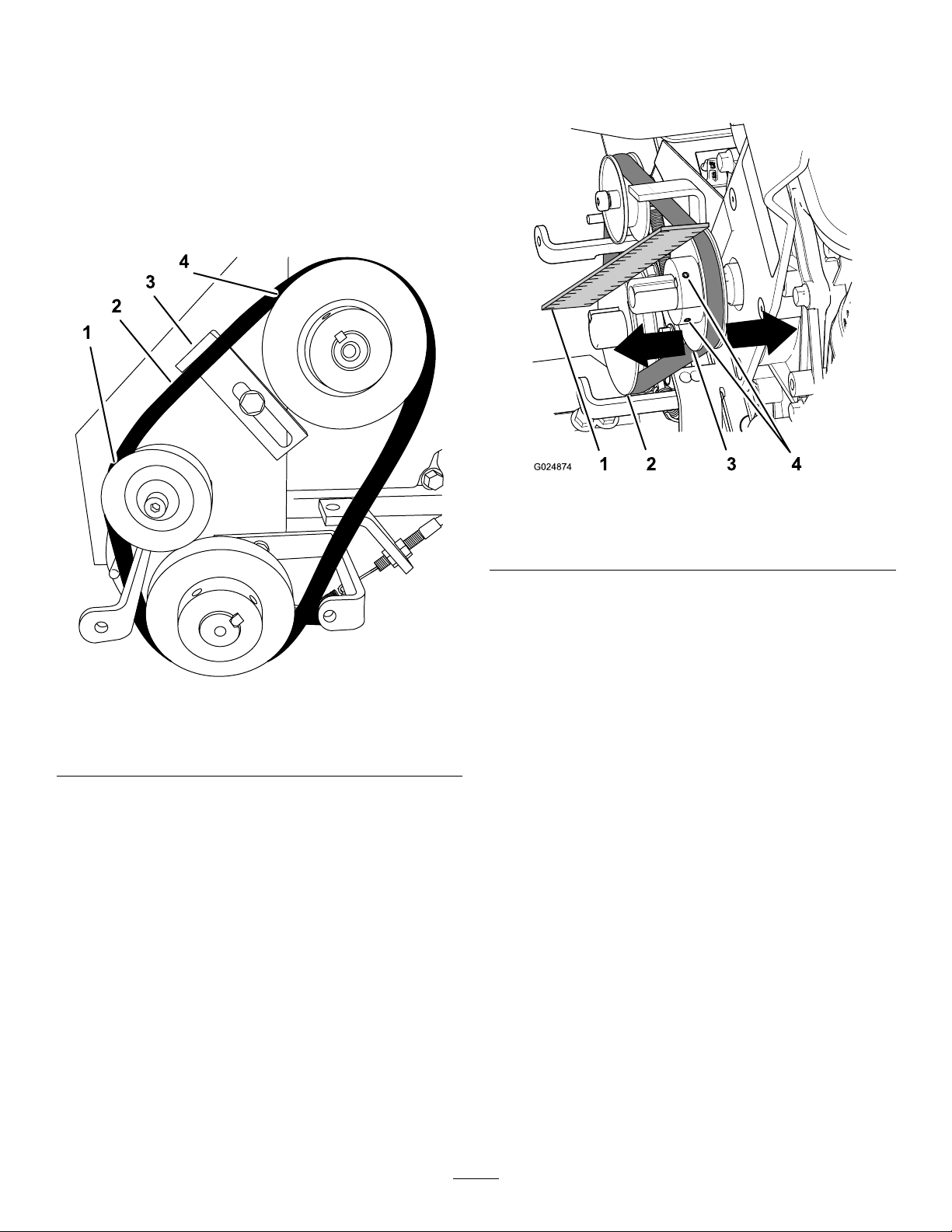
1.Placeastraight-edgeruleracrosstheengine
pulleyandthegearboxpulley(Figure24).
Figure24
1.Straightedge
2.Gearboxpulley4.Setscrew
3.Enginepulley
g024874
Figure23
1.Belt-tensionpulley
2.Belt4.Enginepulley
4.Slipthebeltoffthegearboxpulley(Figure23).
5.Slipthebeltofftheenginepulleyandremove
thebelt(Figure23).
3.Gearboxpulley
InstallingtheBelt
1.EnsuretheDyna-ClutchleverintheSTOP
position.
2.Alignthebeltovertheenginepulley(Figure23).
3.Alignthebeltoverthegearboxpulley(Figure
23).
4.Slipthebeltoverthebelt-tensionpulley(Figure
23).
5.Installthebeltguard;refertoInstallingtheBelt
Guard(page19).
2.Ifthepulleysareoutofalignment,performthe
followingsteps:
A.Loosenthe2setscrewsthatsecurethe
enginepulleytotheengineshaft(Figure
g241621
24).
B.Gentlytaptheenginepulleytowardor
awayfromtheengineuntilthegearboxand
enginepulleysaligntothestraight-edge
ruler(Figure24).
C.Tightenthe2setscrewsthatsecurethe
enginepulleytotheengineshaft(Figure
24).
AdjustingtheDyna-Clutch
Important:Thisadjustmentprocedureaffectsthe
operationoftheDyna-Clutchandiscriticaltothe
safeoperationofthemachine.
Adjustthetension-pulleyspringasneededtotighten
thebelt.
1.MovetheDyna-ClutchlevertotheSTOPposition;
refertoDyna-ClutchLever(page8).
2.Loosenthe2jamnutsthatsecurethebarrelof
theclutchcabletotheclutchbracket,androtate
thenutstoeitherendofthreadsonthebarrel
(Figure25).
20
Page 21
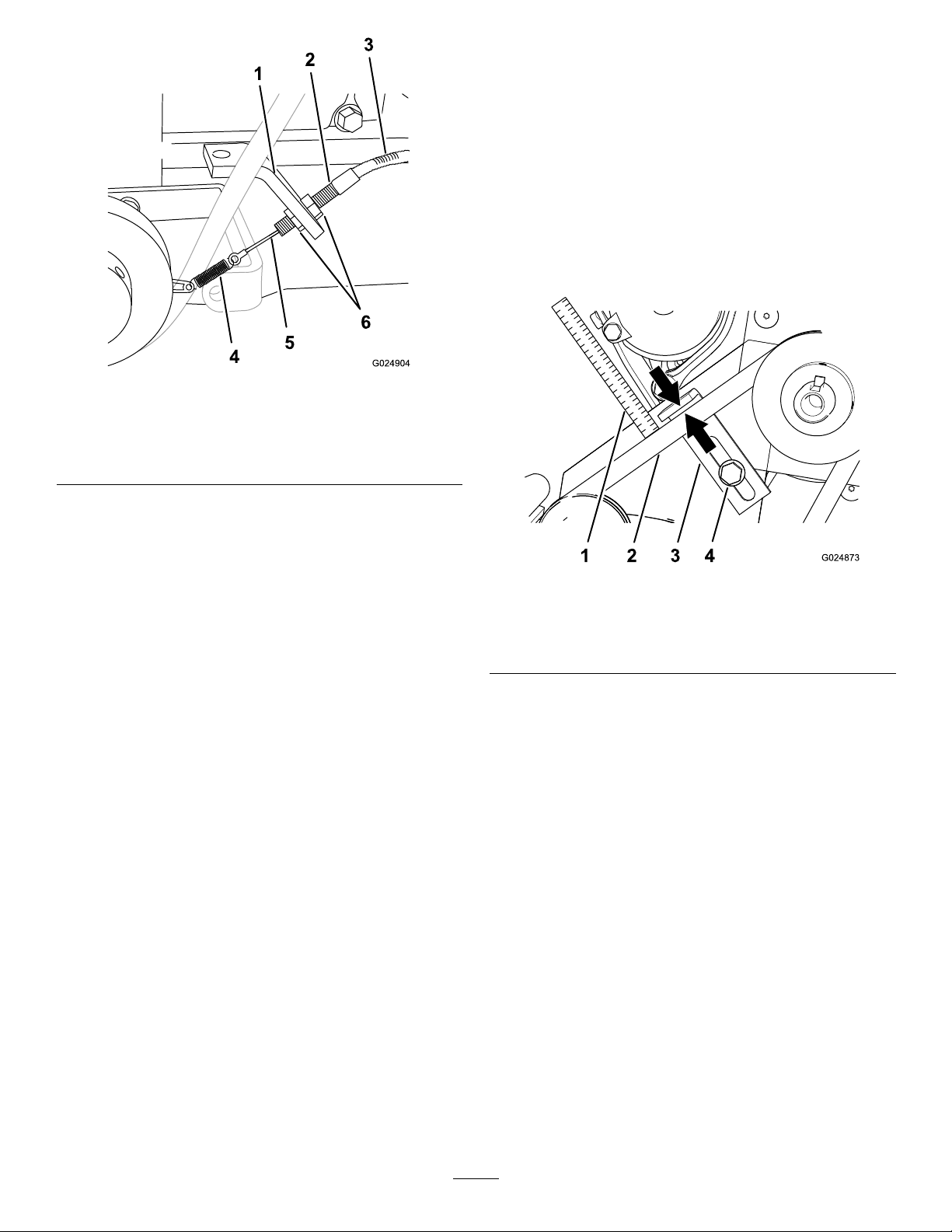
Figure25
1.Clutchbracket4.Spring
2.Barrel
3.Cablehousing
Note:Ifthebladescontinuetorotatewhenthe
Dyna-ClutchisintheSTOPposition,thereistoo
muchtensionontheclutchcable.Shutoffthe
engineandrepeatstep7untilthebladesdo
notrotatewhentheengineisrunningandthe
Dyna-ClutchisintheSTOPposition.
AdjustingtheBeltGuide
1.PlacetheDyna-ClutchleverintheRUNposition.
2.Measuretheairgapbetweenthebeltandthe
beltguide(Figure26).
g024904
5.Cable
6.Locknuts
3.Graspthebarrelwith1handandliftthecable
housinglightly(Figure25).
Note:Liftingthecablehousingatthebarrel
shouldremovetheslackfromthecablebut
applynotensiontothespring.
4.Whileholdingtensiononthecable,useyour
otherhand,rotatethejamnutsuntilthenutsare
ushtotheclutchbracket(Figure25).
5.Tightenthejamnutstosecurethebarreltothe
bracket(Figure25).
6.Checkthetensionofthecontrolcable.Repeat
steps2through4untilthereistensiononthe
Dyna-Clutchcablebutnotensiononthespring.
Note:Ifthereistoomuchtensiononthecable
andspring,theDyna-Clutchwillnotrelease
completely.Ifthereisnotenoughtensiononthe
cable,thecablemaydisconnectfromthepulley
bracket.
7.Ifyouneedtomakeanercableadjustment,
performthefollowing:
A.Loosenthe2jamnutsslightly(Figure25).
Figure26
1.6mm(1/4inch)
measures-airgap
2.Belt4.Hex-headbolt
3.Beltguide
Theairgapshouldbeapproximately6mm(1/4
inch).Ifanadjustmentneedstobedone,performthe
following:
1.Loosenthehex-angeheadboltthatsecures
thebeltguidetotheengineplate(Figure26).
2.Whilekeepingthetopofthebeltguideparallel
tothebelt,movethebeltguidetowardoraway
fromthebeltuntiltheairgapiscorrect(Figure
26).
3.Tightenthehex-angeheadboltthatsecures
thebeltguidetotheengineplate(Figure26).
g024873
B.Rotatethejamnutstoclockwisetoincrease
cabletensionorcounterclockwiseto
decreasetension(Figure25).
C.Tightenthejamnutstosecurethebarrelto
theclutchbracket(Figure25).
8.StartthemachineandsetDyna-Clutchtothe
RUNpositionforafewmoments,thenmovethe
Dyna-ClutchtotheSTOPposition.
21
Page 22
ControlsSystem
AdjustingtheProPitch
Maintenance
AdjustingtheTiltKnob
1.SettheDyna-ClutchlevertotheStopposition,
shutofftheengine,andwaitforallmovingparts
tostop.
2.Disconnectthewirefromthesparkplug.
3.Attachanoverheadlifttotheliftingpointonthe
machineandliftitoffoftheground.
4.Turnthetiltknobuntilthereisenoughcable
slacktoaccessthetiltlocknut(Figure27).
LinkageRod
1.SettheDyna-ClutchlevertotheStopposition,
shutofftheengine,andwaitforallmovingparts
tostop.
2.Disconnectthewirefromthesparkplug.
3.Attachanoverheadlifttotheliftingpointonthe
machineandliftifoffoftheground.
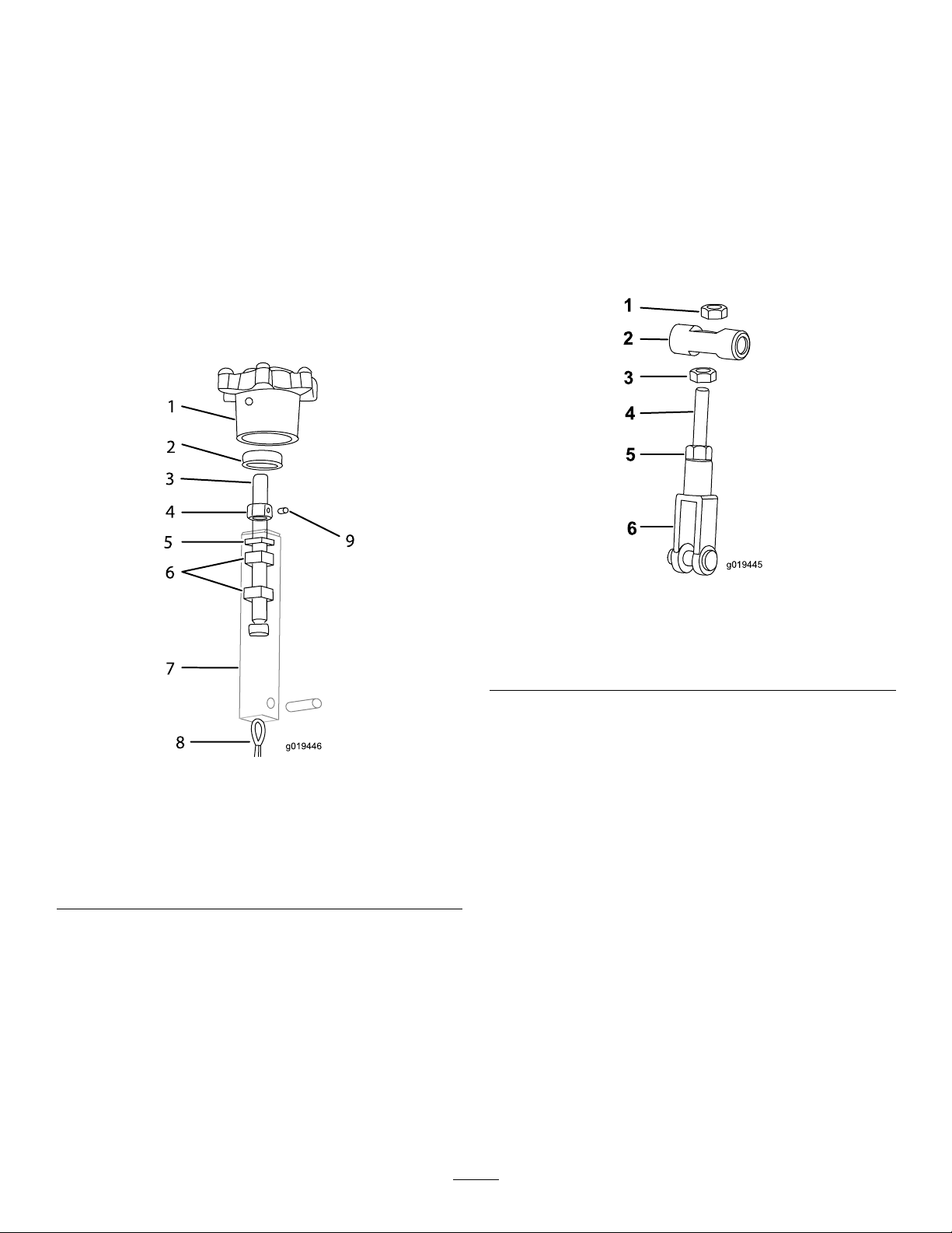
4.Loosenthenutontheupperendofthelinkage
rodtoallowslackintheliftcable(Figure28).
Figure27
1.Tiltknob6.Nut
2.Bearing7.Tiltblock
3.Tiltrod8.Tiltcable
4.Tiltlocknut
5.Washer
5.Tightenthelocknutagainstthebearingthen
loosenitslightly .Setitwiththesetscrew(Figure
27).
6.Adjustthenutsinsidethetiltblocktotakeup
anycableslack.
9.Setscrew
g019445
Figure28
1.Nut4.Linkagerod
2.Swivel
3.Nut6.Yokeend
5.PositiontheProPitchhandleinthefulltilt
position.
g019446
6.Adjustthenutonthebacksideoftheswivel
attheupperendofthelinkageroduntilyou
achievethepropergapofapproximately0.4
mm(1/64inch)betweenthetiltleverandthe
gearcase.
7.Tightenthenutontheoutsideoftheswivelto
lockthelinkagerodintoposition.
5.Nut
Note:Replacethecablesiffulltiltisnolonger
obtainable.
22
Page 23

TestingtheDyna-Clutch Lever
TestingtheDyna-ClutchOperation
Ensurethattheareaisclearofanydebrisor
bystandersbeforebeginningthetestingprocedures.
1.Startthetrowel,engagetheDyna-Clutchlever,
andrunthemachineforafewmoments.
2.MovetheDyna-ClutchlevertotheStopposition.
3.Watchthebladesforanysignofcontinued
rotation.
Ifthebladesdonotstop,thereistoomuch
tensiononthecableandspring.Shutoffthe
engineanddecreasetheamountoftension
toallowtheDyna-Clutchlevertodisengage
completely.
Ensurethatthereisstillenoughtensiononthecable
andspringtopreventpartsfromcomingunhooked
duringoperation.Ifthetendencyforthebladesto
rotatewhentheDyna-Clutchleverisdisengaged
cannotbeadjustedoutofthesystemwithouttakingall
tensionoffofthecableandspring,carefullyinspect
thedrivebeltandDyna-Clutchleversystemforwear
ordamage.Ensurethatallpartsareoperatingfreely .
IftheDyna-Clutchleverdoesnotstoptheblades,see
anAuthorizedServiceDealer.
TestingtheDyna-ClutchLever Adjustment
Important:Ensurethatthetestingofthe
Dyna-Clutchleverisdoneisaclearandopenarea.
Important:Clearthetestareaofbystanders.
1.MovetheDyna-ClutchlevertotheSTOPposition;
refertoDyna-ClutchLever(page8).
2.Startthetrowel.
3.MovethefuelvalvetotheOFFposition(Figure
29).
Figure29
1.Fuelvalve
4.Holdontothehandleandengagethe
Dyna-Clutchlever;refertoDyna-ClutchLever
(page8).
5.Letgoofthehandle.
TheDyna-Clutchlevershouldswitchtothe
STOPpositionwithin1rotation.Ifitdoesnot,
keepclearoftheareaandwaitforthemachine
torunoutoffuel.
2.Offposition
Note:IftheDyna-Clutchdoesnotstopthe
machinewithin1rotation,adjusttheDyna-Clutch
orbringthemachinetoanauthorizedservice
location;refertoAdjustingtheDyna-Clutch
(page20).
6.MovetheDyna-ClutchlevertotheSTOPposition.
AdjustingtheBlades
Adjustthebladestoremoveexcessiveshakingofthe
machine.
1.Disconnectthesparkplugwireandmovethe
Dyna-ClutchlevertotheSTOPposition.
2.Place3or4blocksofequalheightunderthe
stationarybladeguard(outerring)toraisethe
bladesoffoftheoor.
g025040
Important:Youmustmovethefuelvalve
totheOFFpositionbeforecontinuingthis
procedure.
Note:Ensurethattheblocksareclearofthe
bladessothatthebladescanberotatedwithout
touchingtheblocks.
23
Page 24

Figure32
g019517
Figure30
1.Stationarybladeguard
2.Block
3.Measurefromtheoortotheleadingedgeof
theblade.Notethemeasurement.
4.Placeamarkonthebladeandonthespoton
theoorfromwherethemeasurementwas
taken(Figure31).
1.Ruler
2.Spotonoorfromrst
measurement
3.Secondblade
7.Comparethe2measurements.
Iftheheightofthesecondbladeisnotwithin0.8
mm(1/32inch)oftheheightoftherstblade,
adjustthesecondblade.
8.Loosenthelocknutsontheblade(Figure33).
g019516
Figure31
1.Spotontheoorwherethe
measurementwastaken
2.Ruler
3.Blade
5.Rotatethebladesuntilthenextbladeisin
thesamepositionasthepreviouslymeasured
blade.
6.Measurethesecondbladefromthespot
previouslymarkedontheoortothesecond
bladesleadingedge(Figure32).
g019518
Figure33
1.Rodendbearing4.Bladearmlever
g019517
2.Thrustplate5.Bladearm
3.Locknuts
9.Adjustthebladearmleverupordownas
necessarytomakethesecondbladeheight
thesameheightoftherstbladethatwas
measured.
10.Tightenthelocknuts.
11.Repeatasnecessaryfortheremainingblades.
24
Page 25
AdjustingtheBladeArms
Adjustthebladearmsifthemachinestillshakes
excessivelyafterthebladeshavebeenadjusted.
1.Placethemachineonaatsurface.
2.Disconnectthesparkplug.
3.Turnthetiltadjustmentknobcounterclockwise
untilallofthetensionisoffofthetiltadjustment
cableandthebladesareatagainsttheoor.
Bladearmsshouldbeunbentandattothe
oor.Ifabladeisbent,continuethisprocedure
toadjustthebladearm.Ifbladesareunbent
andattotheoor,examinethemachinefor
otherwornparts.
Note:Donotscrewtheknobcompletelyout
ofthehandle.
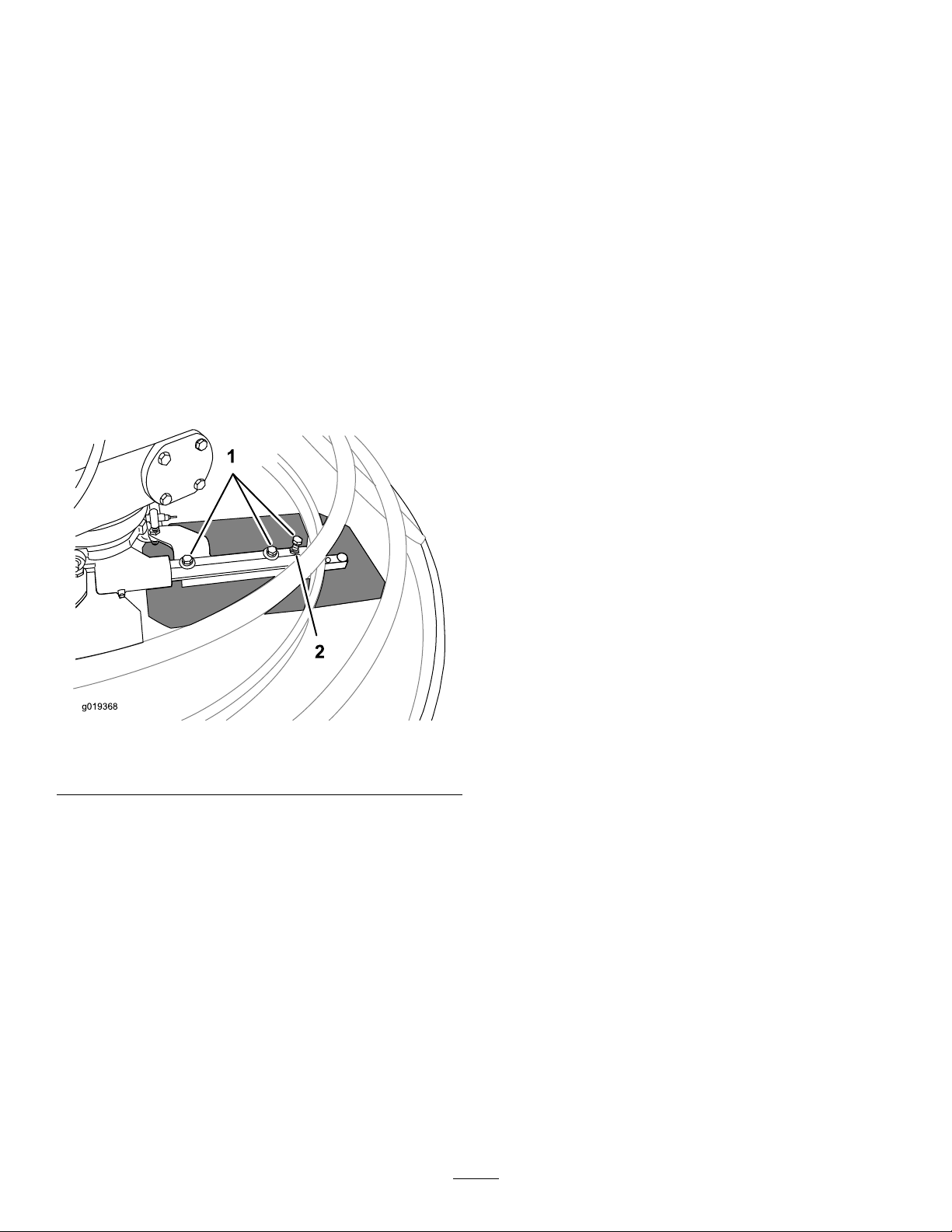
4.Loosenthebolts3to4turns(Figure34).
Storage
1.SettheDyna-ClutchlevertotheStopposition,
shutofftheengine,anddisconnectthe
spark-plugwire.
2.Removedirtandgrimefromtheentiremachine.
Important:Youcanwashthemachinewith
milddetergentandwater.Donotpressure
washthemachine.Avoidexcessiveuseof
water,especiallyneartheengine.
3.Servicetheaircleaner;refertoServicingtheAir
Cleaner(page15).
Changetheengineoil;refertoChangingthe
EngineOil(page17).
4.Forstorageover30days,preparethemachine
asfollows:
A.Addapetroleumbased
stabilizer/conditionertofuelinthe
tank.Followthemixinginstructionsfrom
stabilizermanufacturer.Donotusean
alcohol-basedstabilizer(ethanolor
methanol).
Figure34
1.Bolts2.Locknut
5.Loosenthelocknutandtightentheoutermost
boltuntilthebladelaysatagainsttheoor.
6.Tightenthelocknutandbolts.
7.Repeatforotherbladesasnecessary.
Ifthebladearmcannotbeadjustedtolayat,replace
thebladearm.
Ifthemachinecontinuesshakingexcessivelyafter
thebladearmshavebeenadjusted,examinethe
remainderofthemachineforanyotherwornparts.
Note:Afuelstabilizer/conditionerismost
effectivewhenmixedwithfreshfueland
usedatalltimes.
B.Runtheengineuntilitstopsfromrunning
outoffuel.
C.Choketheengine.
D.Startandruntheengineuntilitwillnotstart
again.
g019368
E.Disposeoffuelproperly.Recycleasper
localcodes.
Important:Donotstore
stabilizer/conditionedfuelover90days.
5.Checkandtightenallbolts,nuts,andscrews.
Repairorreplaceanypartthatisdamaged.
6.Paintallscratchedorbaremetalsurfaces.Paint
isavailablefromyourAuthorizedServiceDealer.
7.Storethemachineinaclean,drygarageor
storagearea.
8.Coverthemachinetoprotectitandkeepitclean.
25
Page 26

Troubleshooting
Problem
Thetrowelbladeturnswhentherecoilis
pulled.
Thetrowelbladesarewearingunevenly.
Thetrowelbounces,rocks,ordigsintothe
concrete.
Thetiltknobisdifculttoturn.
PossibleCauseCorrectiveAction
1.Theclutchisengaged.
2.Theclutchisnotproperlyadjusted.
3.Thebeltguidebracketisbent.
1.Thebladearmisbent.
2.Thebladearmneedtobeadjusted.
3.Thetiltmechanismneedstobe
adjusted.
4.Therodendbearingsarewornor
needstobeadjusted.
1.Thebladearmisbent.
2.Thebladearmneedstobeadjusted.
3.Thearmbearingsareworn.
4.Theoutputshaftisbent.4.SeeanAuthorizedServiceDealer.
1.Thetiltrodandnutareseized.1.Lubricatethetiltrodthreads.
2.Thetiltpivotisnotseatedproperly.
3.Thetiltlocknutneedstobeadjusted.
4.Thethrustplateiswornorhasseized.
5.Thetiltleveriswornorbent.
6.TheProPitchcamisbentorworn.
1.DisengagetheClutch.
2.SeeAdjustingtheDyna-ClutchLever.
3.SeeanAuthorizedServiceDealer.
1.SeeAdjustingtheBladeArms.
2.SeeAdjustingtheBladeArms.
3.SeeAdjustingtheBladeArms.
4.SeeAdjustingtheBladeArms.
1.SeeAdjustingtheBladeArms.
2.SeeAdjustingtheBladeArms.
3.SeeanAuthorizedServiceDealer.
2.SeeAdjustingtheTiltKnob.
3.SeeAdjustingtheTiltKnob.
4.Lubricatethethrustplate.Seean
AuthorizedServiceDealer .
5.SeeanAuthorizedServiceDealer.
6.SeeAdjustingthePro-PitchLinkage
Rod.SeeanAuthorizedService
Dealer.
TheDyna-Clutchleverisdifcultto
engage.
Thebeltslips.
Thegearcaseisemittingagrindingnoise.1.Thebearingsareworn.
Theenginedoesnotstart.
Theenginerunsrough.
1.Thetensionneedstobeadjusted.
2.TheDyna-Clutchleverisworn.2.SeeanAuthorizedServiceDealer.
3.Thecablehasseized.
1.Thetensionontheclutchspringneeds
tobeadjusted.
2.Thebeltisworn.
1.Thechokeisopen.
2.Thefueltankisempty.2.Fillthetankwithfreshfuel.
3.Thesparkplugwireislooseor
disconnected.
1.Thechokeislefton.1.Openthechoke.
2.Theairlterisclogged.
3.
Thefuellineisclogged.
4.Thereiswaterorcontaminantsinthe
fuel.
5.Thesparkplugsarewornorhave
buildupontheelectrodes.
1.SeeAdjustingtheDyna-ClutchLever.
3.SeeanAuthorizedServiceDealer.
1.SeeAdjustingtheDyna-ClutchLever.
2.SeeAdjustingtheTransmissionDrive
BeltTension.
1.SeeanAuthorizedServiceDealer.
1.Closethechokewhenstartingacold
engine.
3.Checktheelectrodegapandcleanor
replacethesparkplug.
2.Cleanorreplacetheairlter.See
ServicingtheAirCleaner.
3.
Cleanthesedimentcup.
4.Drainandllthetankwithfreshfuel.
5.Checktheelectrodegapandcleanor
replacethesparkplug.
26
Page 27

Notes:
Page 28

CaliforniaProposition65WarningInformation
Whatisthiswarning?
Youmayseeaproductforsalethathasawarninglabellikethefollowing:
WARNING:CancerandReproductiveHarm—www.p65Warnings.ca.gov.
WhatisProp65?
Prop65appliestoanycompanyoperatinginCalifornia,sellingproductsinCalifornia,ormanufacturingproductsthatmaybesoldinorbroughtinto
California.ItmandatesthattheGovernorofCaliforniamaintainandpublishalistofchemicalsknowntocausecancer,birthdefects,and/orother
reproductiveharm.Thelist,whichisupdatedannually,includeshundredsofchemicalsfoundinmanyeverydayitems.ThepurposeofProp65isto
informthepublicaboutexposuretothesechemicals.
Prop65doesnotbanthesaleofproductscontainingthesechemicalsbutinsteadrequireswarningsonanyproduct,productpackaging,orliteraturewith
theproduct.Moreover,aProp65warningdoesnotmeanthataproductisinviolationofanyproductsafetystandardsorrequirements.Infact,the
CaliforniagovernmenthasclariedthataProp65warning“isnotthesameasaregulatorydecisionthataproductis‘safe’or‘unsafe.’”Manyofthese
chemicalshavebeenusedineverydayproductsforyearswithoutdocumentedharm.Formoreinformation,gotohttps://oag.ca.gov/prop65/faqs-view-all
AProp65warningmeansthatacompanyhaseither(1)evaluatedtheexposureandhasconcludedthatitexceedsthe“nosignicantrisklevel”;or(2)
haschosentoprovideawarningbasedonitsunderstandingaboutthepresenceofalistedchemicalwithoutattemptingtoevaluatetheexposure.
Doesthislawapplyeverywhere?
Prop65warningsarerequiredunderCalifornialawonly.ThesewarningsareseenthroughoutCaliforniainawiderangeofsettings,includingbutnot
limitedtorestaurants,grocerystores,hotels,schools,andhospitals,andonawidevarietyofproductsAdditionally,someonlineandmailorder
retailersprovideProp65warningsontheirwebsitesorincatalogs.
.
HowdotheCaliforniawarningscomparetofederallimits?
Prop65standardsareoftenmorestringentthanfederalandinternationalstandards.TherearevarioussubstancesthatrequireaProp65warning
atlevelsthatarefarlowerthanfederalactionlimits.Forexample,theProp65standardforwarningsforleadis0.5μg/day,whichiswellbelow
thefederalandinternationalstandards.
Whydon’tallsimilarproductscarrythewarning?
•ProductssoldinCaliforniarequireProp65labellingwhilesimilarproductssoldelsewheredonot.
•AcompanyinvolvedinaProp65lawsuitreachingasettlementmayberequiredtouseProp65warningsforitsproducts,butothercompanies
makingsimilarproductsmayhavenosuchrequirement.
•TheenforcementofProp65isinconsistent.
•CompaniesmayelectnottoprovidewarningsbecausetheyconcludethattheyarenotrequiredtodosounderProp65;alackofwarningsfora
productdoesnotmeanthattheproductisfreeoflistedchemicalsatsimilarlevels.
WhydoesToroincludethiswarning?
Torohaschosentoprovideconsumerwithasmuchinformationaspossiblesothattheycanmakeinformeddecisionsabouttheproductstheybuyand
use.T oroprovideswarningsincertaincasesbasedonitsknowledgeofthepresenceofoneormorelistedchemicalswithoutevaluatingthelevelof
exposure,asnotallthelistedchemicalprovideexposurelimitrequirements.WhiletheexposurefromToroproductsmaybenegligibleorwellwithinthe
“nosignicantrisk”range,outofanabundanceofcaution,T orohaselectedtoprovidetheProp65warnings.Moreover,ifTorodoesnotprovidethese
warnings,itcouldbesuedbytheStateofCaliforniaorbyprivatepartiesseekingtoenforceProp65andsubjecttosubstantialpenalties.
RevA
 Loading...