

Page 1
FormNo.3374-363RevA
G019180
CS-1andCS-2ConcreteSaw
ModelNo.68045—SerialNo.313000001andUp
ModelNo.68046—SerialNo.313000001andUp
Registeratwww.T oro.com.
OriginalInstructions(EN)
*3374-363*A
Page 2
WARNING
1
G019181
Introduction
CALIFORNIA
Proposition65Warning
Thisproductcontainsachemicalorchemicals
knowntotheStateofCaliforniatocausecancer,
birthdefects,orreproductiveharm.
Theengineexhaustfromthisproduct
containschemicalsknowntotheStateof
Californiatocausecancer,birthdefects,
orotherreproductiveharm.
Useofthisproductmaycauseexposureto
chemicalsknowntotheStateofCalifornia
tocausecancer,birthdefects,orother
reproductiveharm.
DANGER
Theremaybeburiedpower,gas,and/ortelephone
linesintheworkarea.Shockorexplosionmay
occurifyoucutintothem.
Thismachineisdesignedtoatsawasphaltandconcrete.It
isnotintendedtocutwoodanyothermaterialotherthan
asphaltandconcrete.
Readthisinformationcarefullytolearnhowtooperateand
maintainyourproductproperlyandtoavoidinjuryand
productdamage.Youareresponsibleforoperatingthe
productproperlyandsafely .
YoumaycontactTorodirectlyatwww .Toro.comforproduct
andaccessoryinformation,helpndingadealer,ortoregister
yourproduct.
Wheneveryouneedservice,genuineToroparts,oradditional
information,contactanAuthorizedServiceDealerorToro
CustomerServiceandhavethemodelandserialnumbers
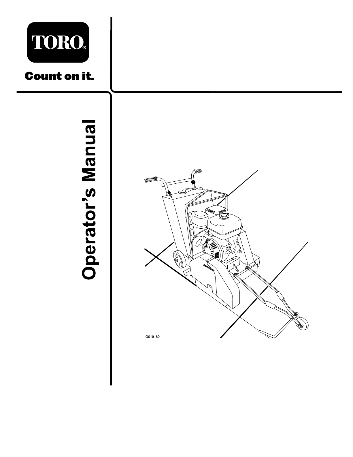
ofyourproductready.Figure1showsthelocationofthe
modelandserialnumbersontheproduct.Writethenumbers
inthespaceprovided.
Havethepropertyorworkareamarkedforburied
linesanddonotdiginmarkedareas.Contactyour
localmarkingserviceorutilitycompanytohavethe
propertymarked(forexample,intheUnitedStates,
call811forthenationwidemarkingservice).
Becauseinsomeareastherearelocal,state,orfederal
regulationsrequiringthatasparkarresterbeusedonthe
engineofthismachine,asparkarresterisincorporatedwith
themuferassembly.
GenuineTorosparkarrestersareapprovedbytheUSDA
ForestryService.
Important:Thisengineisequippedwithaspark
arrestermufer.ItisaviolationofCaliforniaPublic
ResourceCodeSection4442touseoroperatetheengine
onanyforest-covered,brush-covered,orgrass-covered
landwithoutasparkarrestermufermaintainedin
workingorder,ortheengineconstricted,equipped,and
maintainedforthepreventionofre.Otherstatesor
federalareasmayhavesimilarlaws.
Figure1
1.Modelandserialnumberplate
ModelNo.
SerialNo.
Thismanualidentiespotentialhazardsandhassafety
messagesidentiedbythesafetyalertsymbol(Figure2),
whichsignalsahazardthatmaycauseseriousinjuryordeath
ifyoudonotfollowtherecommendedprecautions.
©2012—TheToro®Company
8111LyndaleAvenueSouth
Bloomington,MN55420
Contactusatwww.T oro.com.
2
PrintedintheUSA.
AllRightsReserved
Page 3

Safety
Figure2
1.Safetyalertsymbol
Thismanualuses2otherwordstohighlightinformation.
Importantcallsattentiontospecialmechanicalinformation
andNoteemphasizesgeneralinformationworthyofspecial
attention.
Contents
Introduction..................................................................2
Safety...........................................................................3
SafeOperatingPractices...........................................3
SafetyandInstructionalDecals.................................5
ProductOverview..........................................................7
Controls................................................................8
Specications........................................................10
Attachments/Accessories........................................10
Operation....................................................................11
BeforeyouStart.....................................................11
AdjustingtheHandleBar(Model68046)....................11
RemovingandInstallingtheSawBlade......................11
AdjustingtheCuttingDepth....................................14
AligningthePointer................................................15
AddingFuel...........................................................16
ServicingtheEngineOil..........................................18
StartingandStoppingtheEngine..............................19
CuttingtheJob-SiteSurface.....................................20
ChangingtheCuttingPosition..................................22
TransportingtheMachine........................................25
Maintenance.................................................................26
RecommendedMaintenanceSchedule(s)......................26
Lubrication...............................................................27
GreasingtheMachine.............................................27
LubricatetheElevationScrew..................................27
EngineMaintenance..................................................28
ServicingtheAirFilter............................................28
ChangingtheEngineOil.........................................29
ServicingtheFuelSystem........................................30
ServicingtheSparkPlug..........................................31
ServicingtheSparkArrester.....................................32
BeltMaintenance......................................................33
ServicingtheDriveBelts.........................................33
SawBladeMaintenance...............................................38
CheckingtheConditionandFunction.......................38
Cleaning...................................................................40
CleaningtheMachine..............................................40
Storage........................................................................40
StoringtheMachine................................................40
Troubleshooting...........................................................42
Improperuseormaintenancebytheoperatororowner
canresultininjury.Toreducethepotentialforinjury,
complywiththesesafetyinstructionsandalways
payattentiontothesafetyalertsymbol,which
means:
instruction.Failuretocomplywiththeinstructionmay
resultinpersonalinjuryordeath.
Caution
,
W ar ning
,or
Danger
—personalsafety
SafeOperatingPractices
Thisproductiscapableofamputatinghandsandfeet.Always
followallsafetyinstructionstoavoidseriousinjuryordeath.
WARNING
Engineexhaustcontainscarbonmonoxide,an
odorless,deadlypoisonthatcankillyou.
Donotruntheengineindoorsorinanenclosed
area.
WARNING
Machiningorhandlingstone,masonry,concrete,
metal,andothermaterialscangeneratedust,mists,
andfumescontainingchemicals,suchassilica,
knowntocauseseriousorfatalinjuryorillness,
suchasrespiratorydisease,silicosis,cancer,birth
defects,orotherreproductiveharm.
•Controldust,mist,andfumesatthesource
wherepossible.Watershouldbeusedfordust
suppressionwhenfeasible.
•Usegoodworkpracticesandfollowthe
recommendationsofthemanufactureror
suppliers,OSHA,andotheroccupationaland
tradeassociations.
•Alwaysfollowrespiratoryprecautions.
•Whenthehazardsfrominhalationcannotbe
eliminated,theoperatorandanybystanders
shouldweararespiratorapprovedbyOSHAfor
thematerialbeinghandled.
Training
•ReadtheOperator'sManualandothertrainingmaterial.If
theoperator(s)ormechanic(s)cannotreadEnglish,itis
theowner'sresponsibilitytoexplainthismaterialtothem.
•Becomefamiliarwiththesafeoperationoftheequipment,
operatorcontrols,andsafetysigns.
•Alloperatorsandmechanicsshouldbetrained.The
ownerisresponsiblefortrainingtheusers.
3
Page 4

•Neverletchildrenoruntrainedpeopleoperateorservice
theequipment.Localregulationsmayrestricttheageof
theoperator.
•Theowner/usercanpreventandisresponsiblefor
accidentsorinjuriesoccurringtohimselforherself,other
peopleorproperty.
Preparation
•Decidewhetherwetcuttingordrycuttingisperformed
andevaluatethejobsitematerial(s)todeterminewhat
bladeapplicationisneededtoproperlyandsafelyperform
thejob.Onlyusebladesapprovedforthecutting
operationbythemanufacturerofthesawblade.
•Wearappropriateclothingincludinghardhat,faceshield,
safetyglasses,longpants,safetyshoes,respiratorordust
mask,andhearingprotection.Longhair,looseclothing,
orjewelrymaygettangledinmovingparts.
•Inspectthejobsitewheretheequipmentistobeused
andremoveallobjectssuchasloosesitematerials,rocks,
woodproducts,toolsandhardwarewhichcanbethrown
bythemachine.
•Useextracarewhenhandlinggasolineandotherfuels.
Theyareammableandvaporsareexplosive.
–Useonlyanapprovedcontainertostoreandtransport
fuel.
–Neverremovethegascaporaddfuelwiththeengine
running.Allowtheenginetocoolbeforerefueling.
Donotsmokewhilefuelingthemachine.
–Neverrefuelordrainthemachineindoors.
•Checkthattheguardsareattachedandfunctioning
properly.Donotoperateunlesstheyarefunctioning
properly.
Operation
•Neverrunanengineinanenclosedarea.
•Onlyoperateingoodlight,keepingawayfromholesand
hiddenhazards.
•Ensurethatthebladeiselevatedabovethejob-site
surfacebeforestartingtheengine.Onlystarttheengine
fromtheoperator’sposition.
•Elevatethebladeabovethejob-sitesurfaceaftereach
cuttingpass.
•Ensurethatthebladeiselevatedwhenmovingthe
machinetothejobsite,fromthejobsite,andtoanew
cuttingpath.
•Neveroperatewiththeguardsnotsecurelyinplace.
•Donotchangetheenginegovernorsettingorover-speed
theengine.
•Beforeleavingtheoperatorpositionforanyreason,
elevatethebladeabovethesitesurface,reducethethrottle
toidle,andpressthestopswitch.
•Keephandsandfeetawayfromtheblade.
•Lookbehindanddownbeforebackinguptobesureof
aclearpath.
•Keeppetsandbystandersaway.
•Usecaremovingthemachinebetweenjobsites.Slow
downwhenandusecautionwhenmakingturnsand
whencrossingroadsandsidewalks.
•Donotoperatethemachineundertheinuenceof
alcoholordrugs.
•Usecarewhenloadingorunloadingthemachineintoa
trailerortruck.
•Ensurethattheareaisclearofotherpeoplebefore
operatingthemachine.Stopthemachineifanyoneenters
thearea.
•Neverleavearunningmachineunattended.Always
elevatetheblade,stoptheengineandverifytheblade
hasstoppedrotating.
•Neverjerkthecontrols;useasteadymotion.
•Watchfortrafcwhenoperatingnearorcrossing
roadways.
•Donottouchpartswhichmaybehotfromoperation.
Allowthemtocoolbeforeattemptingtomaintain,adjust,
orservice.
•Ensurethatyouoperatethemachineinareaswhere
therearenoobstaclesincloseproximitytotheoperator.
Failuretomaintainadequatedistancefromtrees,walls,
andotherbarriersmayresultininjuryasthemachine
backsupduringoperationiftheoperatorisnotattentive
tothesurroundings.Onlyoperatetheunitinareaswhere
thereissufcientclearancefortheoperatortosafely
maneuvertheproduct.
•Locatethepinchpointareasmarkedonthemachineand
keephandsandfeetawayfromtheseareas.
•Lightningcancausesevereinjuryordeath.Iflightning
isseenorthunderisheardinthearea,donotoperate
themachine;seekshelter.
MaintenanceandStorage
•Elevatethebladeabovethejob-sitesurfaceandstop
theengine.Waitforthebladetostopbeforeadjusting,
cleaning,orrepairing.
•Cleandebrisfromtheblade,bladeguard,mufers,and
enginetohelppreventres.Cleanupoilorfuelspillage.
•Lettheenginecoolbeforestoringanddonotstorenear
ame.
•Donotstorefuelnearamesordrainindoors.
•Parkthemachineonlevelground.Neverallowuntrained
personneltoservicethemachine.
•Usejackstandstosupportcomponentswhenrequired.
•Carefullyreleasepressurefromcomponentswithstored
energy.
•Removethesparkplugwirebeforemakinganyrepairs.
4
Page 5
•Keephandsandfeetawayfrommovingparts.Ifpossible,
donotmakeadjustmentswiththeenginerunning.
•Keepallpartsingoodworkingconditionandallhardware
tightened.Replaceallwornordamageddecals.
–Neverrefuelthemachineindoors.
–Neverstorethemachineorfuelcontainerinside
wherethereisanopename,suchasnearawater
heaterorfurnace.
•Keepnutsandboltstight.Keepequipmentingood
condition.
•Nevertamperwithsafetydevices.
•Keepthemachinefreeofgrass,leaves,orotherdebris
buildup.Cleanupoilorfuelspillage.Allowthemachine
tocoolbeforestoring.
•Useextracarewhenhandlinggasolineandotherfuels.
Theyareammableandvaporsareexplosive.
–Useonlyanapprovedcontainertostorefuel.
–Neverremovethegascaporaddfuelwhenthe
engineisrunning.Allowtheenginetocoolbefore
refueling.Donotsmoke.
SafetyandInstructionalDecals
Safetydecalsandinstructionsareeasilyvisibletotheoperatorandarelocatednearanyareaofpotential
danger.Replaceanydecalthatisdamagedorlost.
–Neverllacontainerwhileitisinsideavehicle,the
cargoboxofatruck,oranysurfaceotherthanthe
ground.
–Keepcontainernozzleincontactwiththetankduring
lling.
•Stopandinspecttheequipmentifyoustrikeanobject.
Makeanynecessaryrepairsbeforerestarting.
•UseonlygenuineTororeplacementpartstoensurethat
originalstandardsaremaintained.
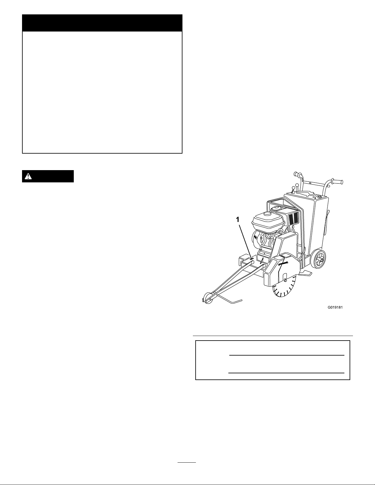
117–4979
1.Rotatingbelt—Keepguardinplace
1.Warning—readthe
Operator’sManual.
2.Warning—keephands
awayfromhotsurfaces.
125–4921
3.Entanglementhazard,
belt—keephandsaway
frommovingparts;keep
allguardsinplace.
5
Page 6
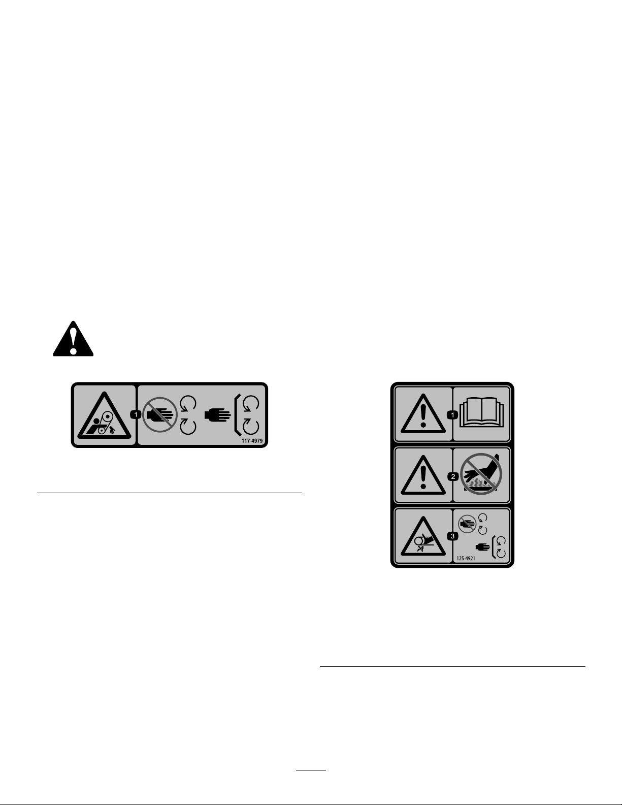
125–4922
00
00
125–4925
1.Cutting/dismembermenthazardofhand,circular
blade—stoptheblade;keephandsawayfrommoving
parts;keepallguardsinplace.
1.Warning—readthe
Operator’sManual.
2.Warning—keephands
awayfrommovingparts;
keepallguardsinplace.
3.Warning—weareye,head,
hearing,andrespiratory
protection.
4.Raiseblade
5.Lowerblade
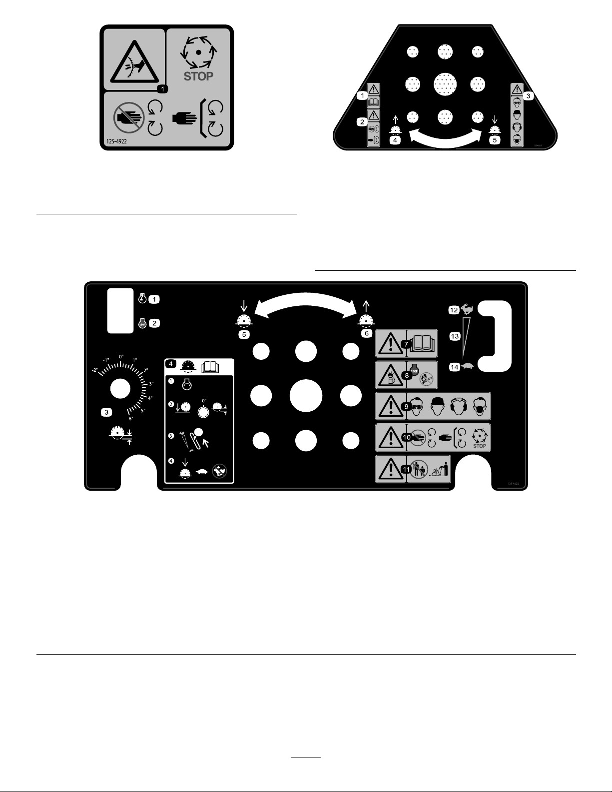
125–4920
1.Engine—run
2.Engine—stop9.Warning—weareye,head,hearing,andrespiratoryprotection.
3.Adjustcuttingheight
4.ReadtheOperator’sManual—1)Starttheengine;2)Setthe
bladeheightto0inches;3)Setthebladespeedtofast;
4)Whenloweringthebladeforcutting,setthespeedtoslow.
5.Lowertheblade12.Fast
6.Raisetheblade13.Variablespeed
7.Warning—readtheOperator’sManual.14.Slow
8.Explosionhazard,fueling—stoptheengineandkeepames
awaywhenfueling.
10.Warning—keepawayfrommovingparts;keepallguardsin
place;waitformovingpartstostop.
11.Warning—keepbystandersawayfromthemachine.
6
Page 7
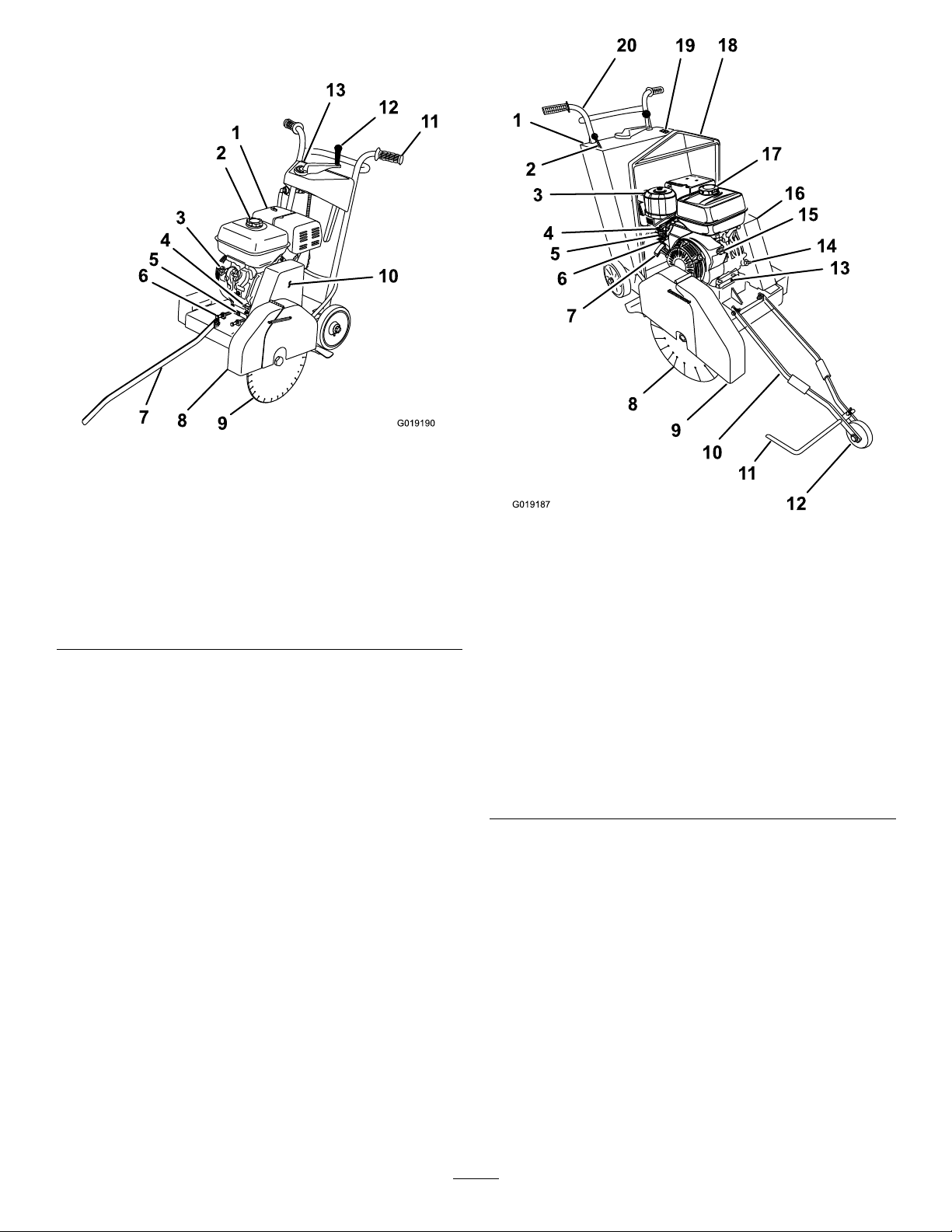
ProductOverview
G019190
2
3
4
5
6
7
8
9
10
11
12
13
1
G019187
1
2
3
4
5
6
8
9
11
12
13
14
15
16
17
18
19
20
10
7
Figure3
Overview(Model68045)
1.Airltercover
2.Fueltankcap
3.Engineswitch10.Beltguard
4.Oilllercap/dipstick
5.Oildrainbolt
6.Belttensionbolt
7.Forwardpointer
8.Bladeguard
9.Sawblade
11.Handlebar
12.Elevationcrank
13.Operatorpanel
Figure4
Overview(Model68046)
1.Operatorpanel
2.Throttlelever12.Pointerwheel
3.Airltercover13.Oildrainbolt
4.Chokelever14.Oilllercap/dipstick
5.Fuelvalvelever
6.Sedimentcup
7.Recoilstarthandle17.Fueltankcap
8.Sawblade18.Liftingbale
9.Bladeguard
10.Pointerfork
11.Forwardpointer
15.Engineswitch(engine
location)
16.Beltguard
19.Engineswitch(operator
panellocation)
20.Handlebar
7
Page 8
Controls
1
2
3
4
G019199
STOP
G019198
12
3 4
5
6
7
G019202
1
2
3
4
5
6
G020236
1 2
3
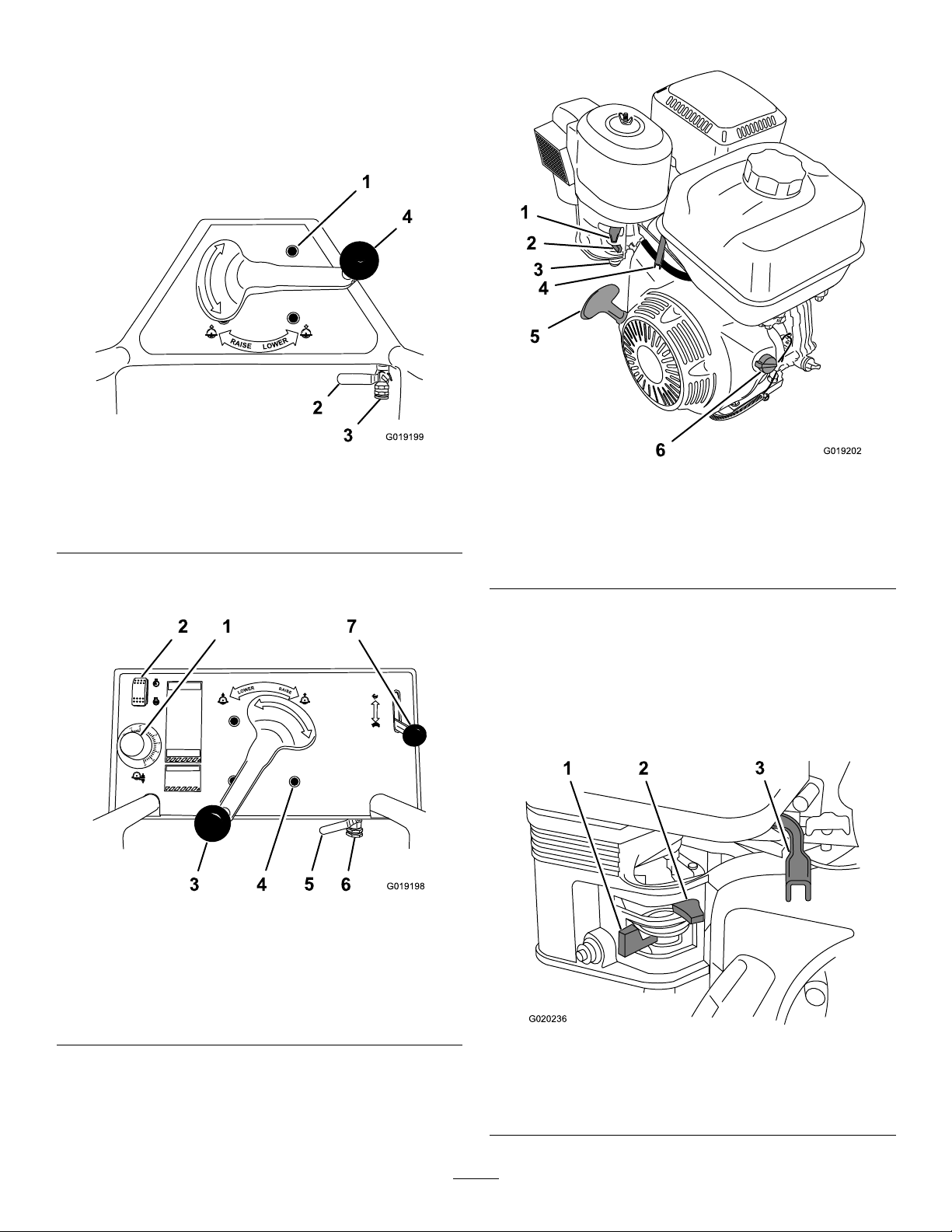
Becomefamiliarwithallthecontrols(Figure5,Figure6,and
Figure7)beforeyoustarttheengineandoperatethemachine.
OperatorPanel(Model68045)
EngineControls
Figure5
OperatorPanel(Model68045)
1.Indexhole3.Waterconnector
2.Watervalvehandle4.Elevationcrank
OperatorPanel(Model68046)
Figure6
OperatorPanel(Model68046)
Figure7
EngineControls(Models68045and68046)
1.Chokelever
2.Fuelvalvelever5.Recoilstarthandle
3.Sedimentcup
4.Throttlelever
6.Engineswitch
FuelValve
Thefuelvalve(Figure8)islocatedunderneaththechoke
lever.TheleverforthefuelvalvemustbemovedtotheOn
positionbeforeattemptingtostarttheengine.Onceyouhave
nishedusingthemachineandyouhaveturnedtheengine
off,movetheleverforthefuelvalvetotheOffposition.
1.Bladedepthgauge5.Watervalvehandle
2.Engineswitch6.Waterconnector
3.Bladeelevationcrank7.Throttle
4.Indexhole
Figure8
EngineControls
1.Fuelvalve3.Throttlelever
2.Chokelever
8
Page 9
ChokeLever
G019203
1
OFF
ON
g018808
1
STOP
G019204
1 2
3
Thechokelever(Figure8)isrequiredwhenstartingacold
engine.Beforepullingontherecoilstarterhandle,move
thechokelevertotheclosedposition.Oncetheengineis
running,movethechokelevertotheopenposition.Do
notusethechokeiftheengineisalreadywarmeduporthe
airtemperatureishigh.
ThrottleLever(Model68045)
Thethrottlelever(Figure8)controlsthespeed(RPM)of
theengine.Itislocatednexttothechokelever.Itsetsthe
engineRPMandthereforecanincreaseanddecreasethe
rotationspeedofthesawblade.Forbestperformanceitis
recommendedyousetthiscontroltothefastposition.
ThrottleControl(Model68046)
Important:Model68046only—donotusethethrottle
leverontheengine.Damagetothethrottlelinkagemay
occurtotheoperatorpanelthrottlecontrol.
Thethrottlecontrolislocatedontheoperatorpanel
(Figure9),andcontrolsthespeed(RPM)oftheengine.It
setstheengineRPMandthereforecanincreaseanddecrease
therotationspeedofthesawblade.Forbestperformanceit
isrecommendedyousetthiscontroltothefastposition.
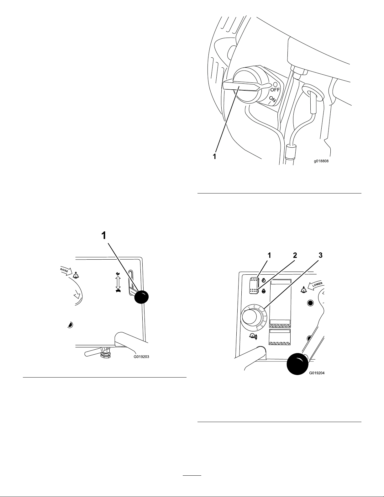
Figure10
1.EngineOn/Offswitch
EngineSwitch(Model68046)
Theengineswitchislocatedontheoperatorpanel(Figure11).
Usetheengineswitchtostoptheengineduringroutine
machineoperationandwhenshuttingthemachineOffin
anemergencysituation.
Figure9
EngineOn/OffSwitch
TheOn/Offswitch(Figure10)allowstheoperatorofthe
machinetostartandstoptheengine.Thisswitchislocated
onthefrontoftheengine.Itismarkedl(ON)andO(OFF).
Tostartthemachine,youmustrstmovethiscontroltothe
Onposition.Whenyouwanttostoptheengine,movethis
switchtotheOffposition.
Figure11
EngineSwitchandBladeDepthGauge(Model68046)
1.Runengine3.Bladedepthgauge
2.Stopengine
RecoilStarter
Tostarttheengine,pullontherecoilstarthandle(Figure7)
quicklytoturntheengineover.Thecontrolsontheengine
9
Page 10

describedabovemustallbesetcorrectlyfortheengineto
start.
OilAlertSystem
TheOilAlertsystemisdesignedtopreventenginedamage
causedbyaninsufcientamountofoilinthecrankcase.
Beforetheoillevelinthecrankcasecanfallbelowasafelimit,
theOilAlertsystemwillautomaticallystoptheengine(the
engineswitchwillremainintheONposition).Iftheengine
stopsandwillnotrestart,checktheengineoillevelbefore
troubleshootinginotherareas.
BladeDepthGauge(Model68046)
Thebladedepthgauge(Figure11)isusedtoindicatethesaw
bladeelevationabovethejobsitesurfaceandblade-cutdepth
intothejob-sitesurface.
Specications
Note:Specicationsanddesignaresubjecttochange
withoutnotice.
Model68045Model68046
Length
Width
Height
Weight
ArborSpeed
(Max.)
ArborDiameter
BladeDiameter
/CuttingDepth
(Max)
92.7cm(36.5inch)†120.1cm(47.3inch)
67.5cm(26.6inch)67.6cm(26.6inch)
87.4cm(34.4inch)93.3cm(36.75inch)
80Kg(175lb)141Kg(310lb)
55.3Hz(3200RPM)55.3Hz(3200RPM)
25.4mm(1inch)25.4mm(1inch)
356mm(14inch)
blade/1 17mm(4.63
inch)depth
†
‡
356mm(14inch)
blade/117mm
(4.63inch)depth
406mm(16inch)
blade/143mm
(5.63inch)depth
457mm(18inch)
blade/168mm
(6.63inch)depth
†Pointerintheupposition.
‡Handlesinthemidposition.
Attachments/Accessories
AselectionofToroapprovedattachmentsandaccessoriesare
availableforusewiththemachinetoenhanceandexpand
itscapabilities.ContactyourAuthorizedServiceDealeror
Distributororgotowww .T oro.comforalistofallapproved
attachmentsandaccessories.
10
Page 11
Operation
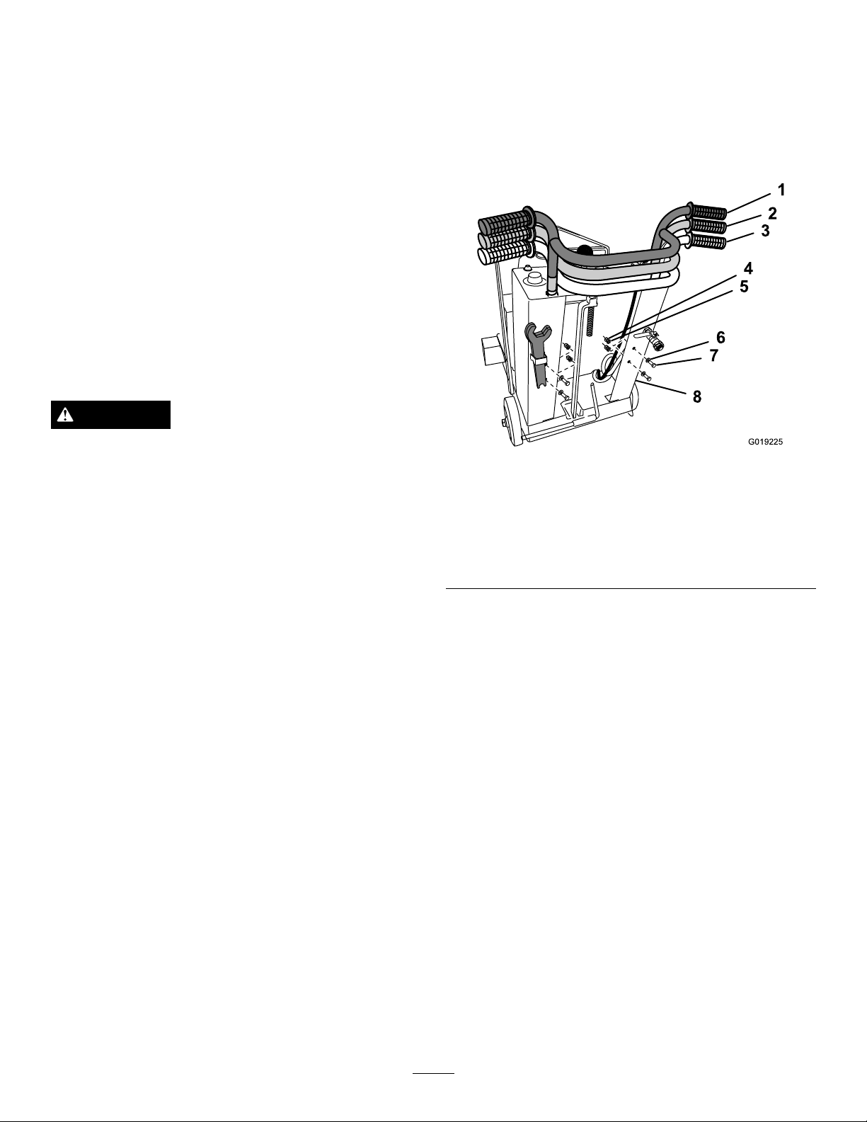
G019225
1
2
3
4
5
6
7
8
Important:Beforeoperating,checkthefuelandoil
level,andremovedebrisfromthemachine.Also,ensure
thattheareaisclearofpeopleanddebris.Y oushould
alsoknowandhavemarkedthelocationsofallutility
lines.
Note:Determinetheleftandrightsidesofthemachine
fromthenormaloperatingposition.
Model68045:Useforsurfacesawingasphaltandconcrete
ofsmallerjobssuchasoorandpavementrepair,expansion
jointcutting,conduitchannelcutting,andotheratwork.
Model68046:Useforsurfacesawingasphaltandconcreteof
jobsthatrequireprecisioncuttingincludingoors,walkways,
ramps,andotheratsurfaces.
BeforeyouStart
DANGER
Identifyandmarkthelocationandrouteofwater,
gas,andelectricallines.Lossoflifeordamageto
propertymayoccuriftheseutilitiesarecut.
AdjustingtheHandleBar (Model68046)
RaisingandLoweringtheHandleBar
1.Locatetheboltsthatsecurethehandlebarstotheback
oftheconsole(Figure12).
Figure12
HandleBarAdjustment(Model68046)
•Usethecorrectbladeforthematerialbeingcut.
•Ensurethatthearbor,collars,andarbornutare
undamaged.
•Installthebladewithbotharborwrenches.
•Whenwetcutting,ensurethatthewaterjetsproduce
adequatewaterow .
•Alignthepointer(s)withthesawblade.
•Removeallequipmentandloosedebrisfromthejobsite
cuttingpath.Removelooseconcrete,asphalt,orboth
fromthecuttingpath.
•Reviewallthemachine’ ssafetydecals.
•Wearahard-hat,respiratorordustmask,hearing
protection,andeyeprotectionwhenoperatingthe
machine.
•Ensurethatyouarefamiliarwithsafetyregulationsand
shutdownproceduresdescribedintheOperator’sManual.
•Ensurethatallguardsareinplaceandingoodcondition.
•Ensurethatthebladeishasnodamageorunusualwear,
andissecuretothearbor.
•Ensurethateveryone,includingchildrenandanimals,
maintainadistanceofatleast50feet(15m)fromthe
machine.Debriscanbethrownoutandinjurepeople
andanimals.
1.Highposition5.Lockwasher
2.Middleposition6.Flatwasher
3.Lowposition7.Bolt
4.Nut
2.Removethebolts,nuts,andwashersthatsecurethe
handlebartotheconsole(Figure12).
3.Raiseorlowerthehandlebar(Figure12).
4.Aligntheholesinthehandlebarwiththemounting
holesintheconsole.
5.Securethehandlebartotheconsolewiththebolts,
nuts,andwashersremovedinstep2(Figure12).
8.Console
RemovingandInstallingthe SawBlade
Important:Beforeremovingorinstallingthesawblade,
removethesparkplugwirefromthesparkplug.
Note:Ensurethatthefollowingconditionsaremetwhen
installingthesawblade:
•Ensurethatthebladeisratedfor3200RPMorgreater
beforeinstallingitonthemachine.
•Checkthecoolingrequirementsforthebladeandcutting
operation.
Alwaysusewaterwithawet-cuttingdiamondblade.A
dry-cuttingbladecanbeusedwithorwithoutwater.
11
Page 12
•Ensurethatthebladespecicationandsizematchesthe
G019281
1
G019213
1
2
1
G019214
cuttingapplication.Checkwiththeblademanufacturer
fortheproperapplication.
•Ensurethatthebladeisnotdamagedwithanyofthe
followingconditions:
–Worncore
–Crackedcore
–Missingsegments
–Wornarborhole
–Worndrive-pinhole
RemovingtheBlade
1.RaisethesawbladetotheStartElevation;referto
stepCinChangingCutDepth(page14).
2.Parkthemachineonalevelsurfaceandturnoffthe
engine;refertoStoppingtheEngine(page19).
3.Ensurethatthemachinesurfacesarecool.
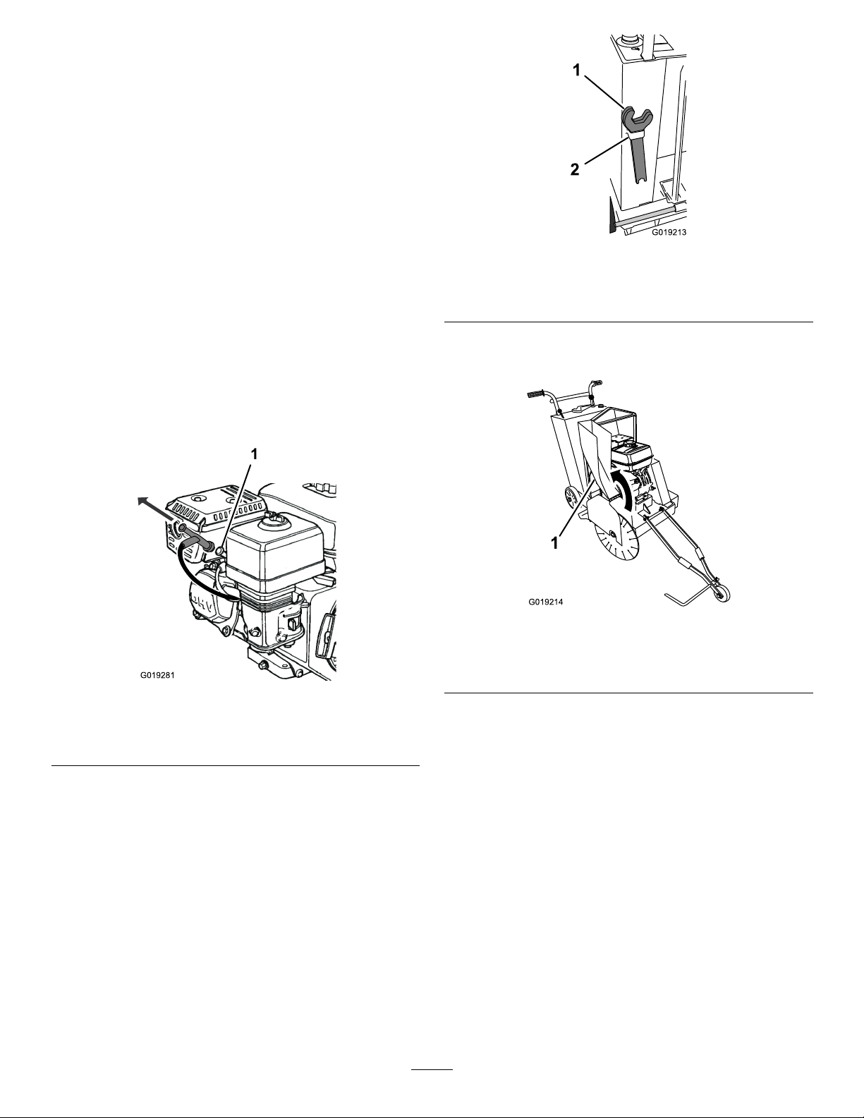
4.Disconnectthesparkplug(
Figure13).
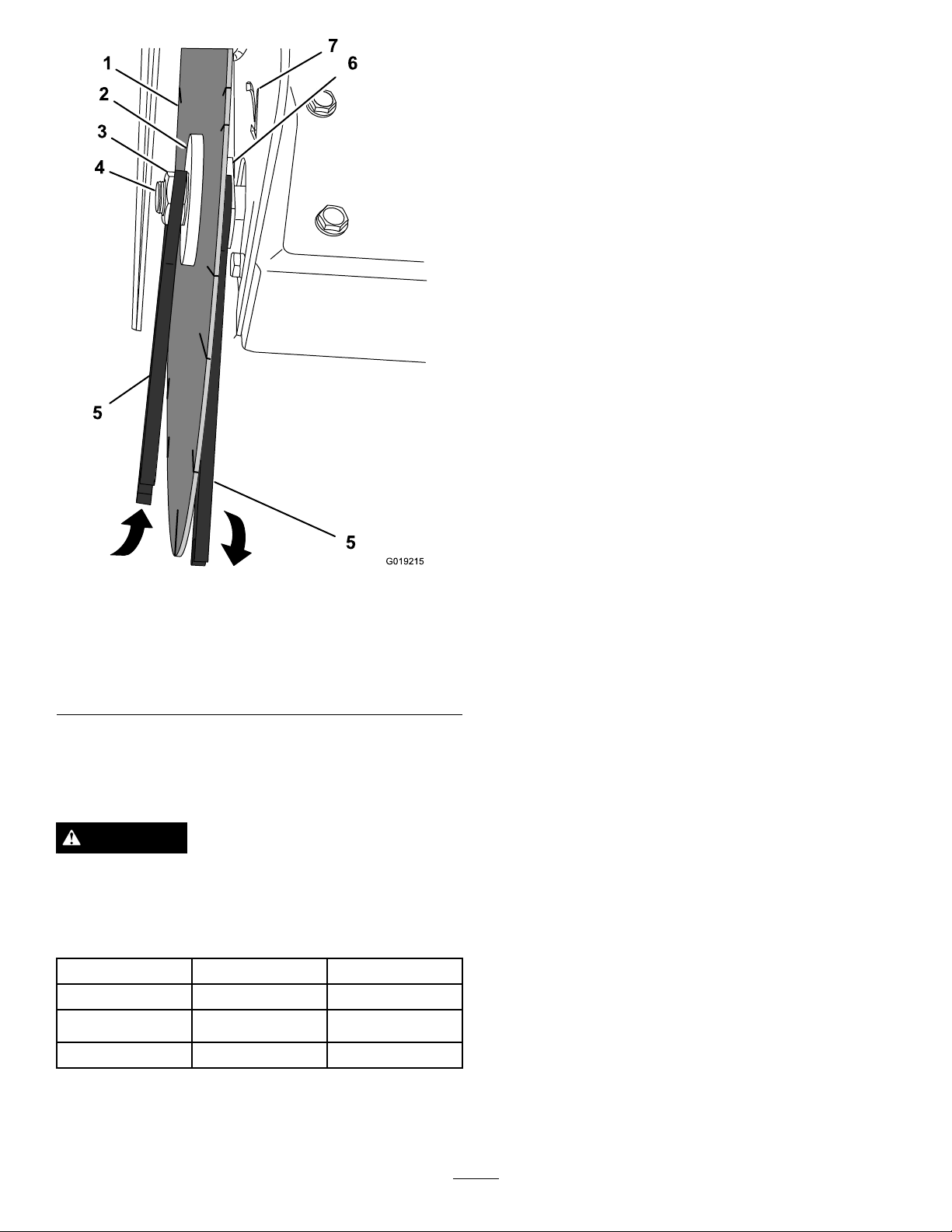
Figure14
ArborWrenchStorage
1.Wrenches
2.Storagebracket
6.Rotatetheforwardsectionofthebladeguardopen
(Figure15).
Figure15
BladeGuard
1.Forwardbladeguardsection
Figure13
DisablingtheEngine
1.Sparkplugwire
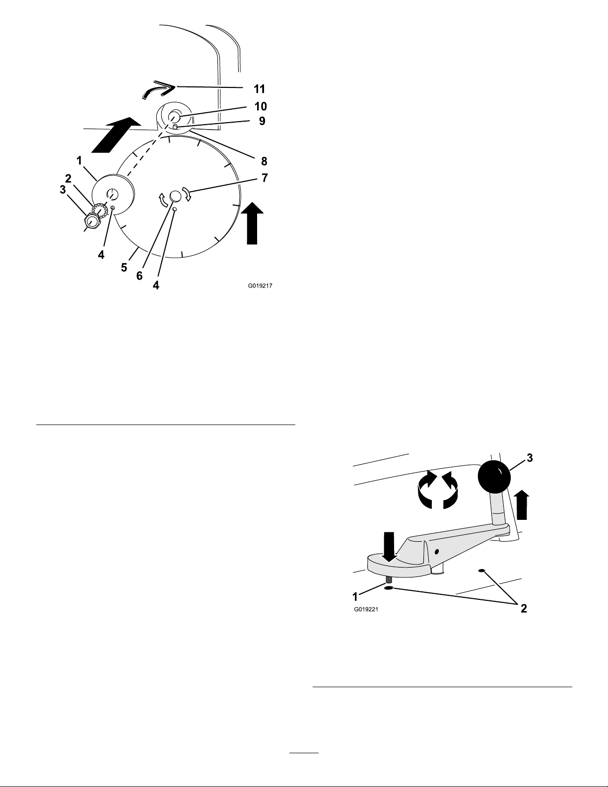
7.Placeonewrenchontheatsoftheinnercollarand
placetheotherwrenchonthearbornut.Removethe
arbornutbyrotatingitcounterclockwise(Figure16).
5.Removethe2wrenchesfromthestoragebracketatthe
back-leftsideoftheoperatorpanel(Figure14).
12
Page 13
G019215
1
2
3
4
5
5
6
7
B.Ensurethatthemachinesurfacesarecool.
C.Disconnectthesparkplug(
Figure13).
D.Removethe2arborwrenchesfromthestorage
bracketattheback-leftsideoftheoperatorpanel;
refertoRemovingtheBlade(page12).
E.Opentheforwardsectionofthebladeguard;
referto
RemovingtheBlade(page12).
F.Inspecttheoutercollar,innercollar,drivepin,
andarborfordamage.Cleanthecollarclamping
surfaces,drivepin,andarborwithacleanrag.
G.Inspecttheinnercollarandensurethatitis
mountedtightonthearbor.
H.Removeanyburrsonthearbor,collarclamping
surfacesandsawbladeclampingsurfaces.
I.Inspectthebladeguardandthewatertubesinside
thebladeguardfordamage.
2.Installthebladeasfollows:
A.Ensurethattherotationarrowonthesawblade
pointsinthesamedirectionastherotationarrow
ontheouterbladeguardside.
Note:Ensurethatthebladeelevationisraised
adequatelytoinstalltheblade.
Figure16
BladeandArbor
1.Sawblade
2.Outercollar
3.Arbornut7.Arborrotationarrow
4.Arbor
5.Wrench
6.Innercollar
arborandmovethebladetowardtheinnercollar
Figure17).
(
B.Alignthearborholeinthesawbladetothe
8.Removethelockwasher,outercollar,andsawblade.
RefertoInstallingtheBlade(page13)
InstallingtheBlade
DANGER
Donotrunthemachinewithlooseormissingarbor
parts.
Important:Alwaysusethepropersizebladeguardand
splashguard.
BladeGuardSize
35.56cm(14in)StandardOptional
40.64cm(16in)Optional
Model68045Model68046
45.72cm(18in)Standard
1.Dothefollowingbeforeinstallingthesawblade:
A.Parkthemachineonalevelsurfaceandturnoff
theengine;refertoStoppingtheEngine(page19).
13
Page 14
G019217
1
2
3
4
5
6
4
8
9
10
11
7
H.Placeonearborwrenchontheatsoftheinner
G019221
1
2
3
collarandplacetheotherwrenchonthearbor
nut.Tightenthearbornutbyrotatingitclockwise.
3.Lowerthefrontbladeguardsection,stowthearbor
wrenchedinstoragebracket,andconnectthespark
plug.
4.Starttheengineandallowthemachineto
runatfullthrottlefor30seconds;referto
StartingtheEngine(page19).
5.Stoptheengine.
AdjustingtheCuttingDepth
Important:Forcutdepthlimits,refertothemachine
Specications(page10).
Note:Rotatetheelevationcrankclockwisetoraisetheblade;
rotatetheelevationcrankcounterclockwisetolowertheblade.
ChangingCutDepth
Figure17
BladeInstallation
1.Outercollar7.Rotationarrow(sawblade)
2.Lockwasher8.Innercollar
3.Arbornut9.Drivepin
4.Drive-pinhole10.Arbor
5.Sawblade11.Rotationarrow(blade
guard)
6.Arborhole
C.Alignthedrive-pinholeinthebladetothedrive
pinthatisprotrudingfromtheinnercollar.Seat
thebladeagainsttheinnercollar(Figure17).
Important:Ensurethatthesawbladehasa
sliptwiththearboranddrivepin.Ifthere
isexcessivemovementbetweentheblade
andthearborandpin,replacethewornparts
beforeoperatingthemachine.
Note:Checkthatthewatertubesinsidetheblade
guardareclearoftheblade.
Important:Eachrevolutionofthebladeelevationcrank
raisesorlowersthebladeapproximately11mm(7/16
inch).
1.AdjustthesawbladetotheStartElevationbydoing
thefollowing:
A.Alignthemachinetothecuttingpathofthe
job-sitesurface.
B.Usingthebladeelevationcrank(Figure18),rotate
thecrankcounterclockwisetolowertheblade
untiltheittouchesthejob-sitesurface.
Note:Thebladeisatthe+0mm(+0inch)
elevation.
D.Aligntheoutercollartothearborandmoveit
towardtheblade(
Figure17).
E.Alignthedrive-pinholeintheoutercollarwiththe
drivepinprotrudingthroughthesawblade,and
thenseatthecollaragainsttheblade(Figure17).
F.Rotatetheoutercollarandsawbladeinthe
oppositedirectionoftherotationarrowonthe
bladeguardtoremoveanyresidualdrivepin
1.Indexpin3.Elevationcrank
2.Index-pinhole
Figure18
Elevationcrank
backlash
G.Installthelockwasherandarbornut(
Figure17).
C.Rotatetheelevationcrank1revolutionclockwise
toraisethebladeelevation(Figure18).The
machineisattheStartElevation.
14
Page 15
Note:TheStartElevationiswhenthesaw
STOP
G019222
21
3
4
bladeisat+11mm(+7/16inch)abovethe
job-sitesurface.Raisethesawbladetothestart
elevationwhenmovingthemachine,maintaining
themachine,andstartingandstoppingtheengine
2.Adjustthecutdepthofthesawbladeasfollows:
•Rotatetheelevationcrankclockwisetoraisethe
bladeelevation.
•Rotatetheelevationcrankcounterclockwiseto
lowerthebladeelevation.
AdjustingtheBlade-DepthGauge
(Model68046)
1.Adjustthebladeelevationtothe+0mm(+0
inch)elevation;refertostepsAandBin
ChangingCutDepth(page14).
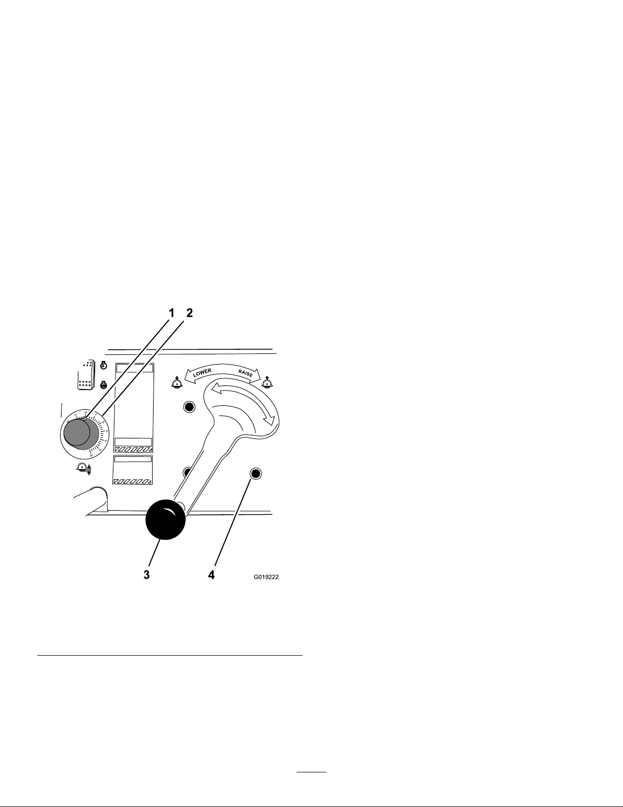
2.Rotatethedialoftheblade-depthgaugeuntilthe
pointer(white)isalignedwiththe“-0”markonthe
gauge(Figure18).
LockingtheBladeElevation
Thebladeelevationcanbelockedwhenmaintainingtheblade
elevationisdesirable.Lockthebladeelevationasfollows:
1.Raiseorlowerthesawbladebyrotatingtheelevation
crankuntilthedesiresbladeelevationisachieved
(Figure18).
2.Ifnecessary,rotatetheelevationcranktoalignthe
indexpininthebottomofthecrankhandlewitha
index-pinholeintheoperatorpanel(Figure18).
3.Pulltheelevationcrankuptoengagetheindexpinin
thehole(Figure18).
Note:Tounlockthebladeelevation,pushdownthe
elevationcranktodisengagetheindexpinfromthe
indexhole.
AligningthePointer
Note:Model68045hasafrontpointer.Model68046hasa
frontandbackpointer.
1.EnsurethatthesawbladeisattheStartElevation;
refertostepCinChangingCutDepth(page14).
Figure19
BladeDepthGauge
1.Dialandpointer3.Elevationcrank
2.Blade-depthgauge4.Index-pinhole
2.Parkthemachineonalevelsurfaceandturnoffthe
engine;refertoStoppingtheEngine(page19).
3.Ensurethatthemachinesurfacesarecool.
Note:Ensurethatthebladeisinstalled;referto
InstallingtheBlade(page13).
AligningtheFrontPointer
Note:Thefrontpointeralignmentprocedurerequiresa1.2
m(4ft)minimumlengthofmasonline.
1.Lowertheforwardpointer.
2.Pullalengthofmasonlineacrossthesurfaceofthe
saw-bladecoreandextendittotheendofthepointer
(onestraightline)asshowningureFigure20.
3.Adjustthepointerpositionasfollows:
•Model68045—Alignthefrontpointerbycarefully
bendingthebarofthepointeruntilitisaligned
withthemasonline(Figure20).
3.RaisethesawbladetotheStartElevation;referstep
CinChangingCutDepth(page14).
Note:Refertothebladedepthgaugewhenraising
andloweringthesawblade(Figure19).
15
Page 16

G019226
1
2
3
Figure20
G019228
1
2
3
4
5
6
G019231
1
2
3
4
6
7
5
PointerAlignment(Model68045)
1.Pointer
2.Mason’sline
3.Saw-bladecore
•Model68046—Alignthefrontpointerbydoing
thefollowing:
A.Loosenthumbscrewthatsecurestheforward
pointertothepointerfork(
Figure21
ForwardPointerAlignment(Model68046)
1.Pointerfork4.3–6mm(1/8–1/4inch)
2.Thumbscrew5.Masonline
3.Forwardpointer
6.Saw-bladecore
Figure21).
Figure22
RearPointerAlignment(Model68046)
1.Forwardpointer
2.Sawblade
3.Rearpointer
4.Chalkline
5.3–6mm(1/8–1/4inch)
6.Thumbscrew
7.Console
2.Alignthesawbladeandtheforwardpointertotheline
markingthejobsitesurface(
Figure22).
3.Atthebackoftheconsole,loosenthumbscrewthat
securesthepointertothebackofthebaseandrotate
thepointerdown(Figure22).
4.Slidethepointerleftorrighttoalignittotheline
markingthejobsitesurface,andelevatethepointer3–6
mm(1/8–1/4inch)abovethesitesurface(Figure22).
5.Tightenthethumbscrewthatsecuresthepointerto
baseofthemachine(Figure22).
B.Slidethepointerleftorrighttoalignit
withthemasonline,andelevated3–6mm
(1/8–1/4inch)abovethejobsitesurface
(Figure21).
C.Tightenthethumbscrewthatsecures
theforwardpointertothepointerfork
(Figure21).
AddingFuel
•Forbestresults,useonlyclean,fresh,unleadedgasoline
withanoctaneratingof87orhigher((R+M)/2rating
method).
•Oxygenatedfuelwithupto10%ethanolor15%MTBE
byvolumeisacceptable.
•DoNotuseethanolblendsofgasoline(suchasE15
AligningtheRearPointer(Model68046)
Note:Therearpointeralignmentprocedurerequiresa3m
(10ft)minimumlengthofchalkline.
Note:Alignthefrontpointerbeforealigningtherear
pointer;refertoAligningtheFrontPointer(page15).
1.Marka3m(10ft)orlongerlineonthejobsitesurface
bysnappingachalklineonthesurface(
Figure22).
orE85)withmorethan10%ethanolbyvolume.
Performanceproblemsand/orenginedamagemayresult
whichmaynotbecoveredunderwarranty.
•DoNotusegasolinecontainingmethanol.
•DoNotstorefueleitherinthefueltankorfuelcontainers
overthewinterunlessafuelstabilizerisused.
•DoNotaddoiltogasoline.
16
Page 17

DANGER
WARNING
Incertainconditions,gasolineisextremely
ammableandhighlyexplosive.Areorexplosion
fromgasolinecanburnyouandothersandcan
damageproperty.
•Fillthefueltankoutdoors,inanopenarea,
whentheengineiscold.Wipeupanygasoline
thatspills.
•Neverllthefueltankinsideanenclosedtrailer.
•Donotllthefueltankcompletelyfull.Add
gasolinetothefueltankuntilthelevelis1/4to
1/2inch(6to13mm)belowthebottomofthe
llerneck.Thisemptyspaceinthetankallows
gasolinetoexpand.
•Neversmokewhenhandlinggasoline,andstay
awayfromanopenameorwheregasoline
fumesmaybeignitedbyaspark.
•Storegasolineinanapprovedcontainerand
keepitoutofthereachofchildren.Neverbuy
morethana30-daysupplyofgasoline.
•Donotoperatewithoutentireexhaustsystemin
placeandinproperworkingcondition.
Gasolineisharmfulorfatalifswallowed.Long-term
exposuretovaporscancauseseriousinjuryand
illness.
•Avoidprolongedbreathingofvapors.
•Keepfaceawayfromnozzleandgastankor
conditioneropening .
•Keepgasawayfromeyesandskin.
Important:Donotmixoilwithgasoline.
RecommendedFuel
UnleadedGasoline
U.S.
Except
U.S.
Pumpoctanerating87orhigher
Researchoctanerating92orhigher
Pumpoctanerating87orhigher
UsingStabilizer/Conditioner
Useafuelstabilizer/conditionerinthemachinetoprovide
thefollowingbenets:
•Keepsgasolinefreshduringstorageof90daysorless.
Forlongerstorageitisrecommendedthatthefueltank
bedrained.
DANGER
Incertainconditionsduringfueling,static
electricitycanbereleasedcausingasparkwhich
canignitethegasolinevapors.Areorexplosion
fromgasolinecanburnyouandothersandcan
damageproperty.
•Alwaysplacegasolinecontainersontheground
awayfromyourvehiclebeforelling.
•Donotllgasolinecontainersinsideavehicleor
onatruckortrailerbedbecauseinteriorcarpets
orplastictruckbedlinersmayinsulatethe
containerandslowthelossofanystaticcharge.
•Whenpractical,removegas-poweredequipment
fromthetruckortrailerandrefueltheequipment
withitswheelsontheground.
•Ifthisisnotpossible,thenrefuelsuch
equipmentonatruckortrailerfromaportable
container,ratherthanfromagasolinedispenser
nozzle.
•Cleanstheenginewhileitruns.
•Eliminatesgum-likevarnishbuildupinthefuelsystem,
whichcauseshardstarting.
Important:Donotusefueladditivescontaining
methanolorethanol.
Addthecorrectamountofgasstabilizer/conditionertothe
gas.
Note:Afuelstabilizer/conditionerismosteffectivewhen
mixedwithfreshgasoline.Tominimizethechanceofvarnish
depositsinthefuelsystem,usefuelstabilizeratalltimes.
FillingtheFuelTank
Note:Thefueltankcapacityis6.1liter(1.61USGallon).
1.Parkthemachineonalevelsurface,stoptheengine,
andallowtheenginetocool.
2.Cleanaroundthefueltankcapandremoveit
(
Figure23).
•Ifagasolinedispensernozzlemustbeused,
keepthenozzleincontactwiththerimofthe
fueltankorcontaineropeningatalltimesuntil
fuelingiscomplete.
17
Page 18

G019224
Figure23
0 20 40 60
80
10 0°F
-20 -10 0 10 20 30 40 °C
5W–30 · 10 W– 30
30
1
G019298
1
2
G018670
3
1.Fueltankcap
3.Addunleadedgasolinetothefueltank,untilthelevelis
1/4to1/2inchbelowthebottomofthellerneck.
Important:Thisspaceinthetankallowsgasoline
toexpand.Donotllthefueltankcompletelyfull.
Note:SAE10W-30isrecommendedforgeneraluse.Other
viscositiesshowninthechartmaybeusedwhentheaverage
temperatureinyourareaiswithintheindicatedrange.
CheckingtheEngineOilLevel
Important:Runningtheenginewithlowoillevelcan
causeenginedamage.Thistypeofdamageisnot
coveredbywarranty.
Theengineisequippedwithanoilalertsystemthatwill
automaticallystoptheenginebeforetheoillevelfalls
belowthesafelimit.
1.Ifthesawbladeisinstalled,dothefollowing:
A.Ensurethatthesawbladeisatthe
StartElevation;refertostep
AdjustingtheCuttingDepth(page14).
B.Removethesawblade;referto
RemovingtheBlade(page12).
2.Leveltheenginebyraisingorlowering
itwiththeelevationcrank;referto
AdjustingtheCuttingDepth(page14).
3.Cleanaroundtheoildipstick.
4.Removetheoilller/dipstickandwipeitclean
(Figure25).
Cin
4.Installthefueltankcapsecurely.
5.Wipeupanygasolinethatmayhavespilled.
ServicingtheEngineOil
ServiceInterval:Beforeeachuseordaily—Checktheengine
oillevel.
Important:Use4-strokemotoroilthatmeetsofexceeds
therequirementsforAPIservicecategory
equivalent).AlwayschecktheAPIservicelabelonthe
oilcontainertobesureitincludestheSJorlater(or
equivalent).
Figure24
RecommendedOilViscosity
SJ or later
(or
Figure25
OilFiller/DipStick
1.Oilllercap/dipstick
2.Fillerport
3.DrainPlug
5.Inserttheoilller/dipstickintothellerneckas
showningureFigure26,butdonotthreaditinto
thellerneck.
1.Oilviscosityrangeforambientoperatingtemperatures
18
Page 19

1
2
G018669
Figure26
G019270
MaximumandMinimumOilLevels
1.Upperoillimit2.Loweroillimit
Note:Onmodel68046machines,donotusethe
throttlecontrolleverontheengine.
4.Ontheengine,movetheleverofthefuelvalveto
theOnposition—allthewaytotheright;referto
FuelValve(page8).
5.Tostartacoldengine,movethechokelevertothe
Closedposition—allthewaytotheleft;referto
ChokeLever(page9).
Note:T orestartawarmengine,leavethechokelever
intheOpenposition(allthewaytotheright).
6.Ontheengine,rotatetheengineswitchtotheOn
position;refertoEngineOn/OffSwitch(page9).
7.Pulltherecoilstarthandlelightlyuntilyoufeel
resistance,thenpullthehandlebriskly .Returnthe
starterhandlegently(Figure27).
6.Removetheoilller/dipstickfromthellerportand
lookattheendofthedipstick.Theoillevelshouldbe
tothetopoftheupperlimitrange(Figure26).
Important:Donotoverllthecrankcasewithoil
becausetheenginemaybedamaged.
7.Iftheoillevelislow ,slowlypouronlyenoughoilinto
theenginecrankcasetoraisetheleveltotheupperlimit.
8.Threadthedipstickintothellerporthandtight.
9.Ifthemachineisbeingoperated,installthesawblade;
reference
InstallingtheBlade(page13).
StartingandStoppingthe Engine
StartingtheEngine
1.RaisethesawbladetotheStartElevation;referto
stepCinAdjustingtheCuttingDepth(page14).
2.Model68046—Ontheoperatorpanel,press
theengineswitchtotheRunposition;referto
EngineSwitch(Model68046)(page9).
3.Positionthethrottleasfollows:
•Model68045—Ontheengine,movethethrottle
leverawayfromtheMIN.position,1/3of
thewaytowardtheMAXposition;referto
ThrottleLever(Model68045)(page9).
•Model68046—Ontheoperatorpanel,move
thethrottlecontrolawayfromtheSlowposition,
1/3ofthewaytowardtheFastposition;referto
ThrottleControl(Model68046)(page9).
Figure27
StartingtheEngine
8.IfthechokeleverissettotheClosedpositionto
starttheengine,graduallymovethechokeleverback
towardtheOpenpositionastheenginewarmsup.
Iftheenginestallsorhesitates,movethechokelever
backtowardstheClosedpositionuntiltheengineruns
smooth.Allowtheenginetowarmup,thenmovethe
chokelevertotheOpenposition.
StoppingtheEngine
WARNING
Inanemergencysituation,stoptheengine
immediately.
Important:Duringnormaloperation,iftheenginehas
beenworkinghardorishot,letitrunforaminutebefore
stoppingtheengine.Thishelpstocooltheengine
beforestopping .
Duringnormaloperatingconditions,shutdowntheengine
asfollows:
19
Page 20

1.RaisethesawbladetotheStartElevation;referto
AdjustingtheCuttingDepth(page14)
CuttingtheJob-SiteSurface
2.EnsurethatthechokeleverisintheOffposition;refer
toChokeLever(page9).
3.Dothefollowingtostoptheengine:
•Model68045
A.Ontheengine,movethethrottle
levertotheMIN.position;referto
ThrottleLever(Model68045)(page9).
B.RotatetheengineswitchtotheOffposition;
refertoEngineOn/OffSwitch(page9).
•Model68046
A.Ontheoperatorpanel,movethethrottle
controltotheSlowposition;referto
ThrottleControl(Model68046)(page9).
B.Ontheoperatorpanel,presstheengine
switchtotheStopposition;referto
EngineSwitch(Model68046)(page9).
C.Ontheengine,rotatetheengine
switchtotheOffposition;referto
EngineOn/OffSwitch(page9).
4.MovetheleveronthefuelvalvetotheOffposition;
refertoFuelValve(page8).
EmergencyStop
Inanemergencysituation,shutdownthemachineasfollows:
•Model68045—Ontheengine,rotatetheengineswitchto
theOffposition;refertoEngineOn/OffSwitch(page9).
•Model68046—Ontheoperatorpanel,Press
theengineswitchtotheStopposition;referto
EngineSwitch(Model68046)(page9).
CAUTION
•Operatethemachinewiththesafetyguardsin
placeandingoodcondition.
•Donotoperatethemachinewithablade
diameterlargerthanthespeciedcapacity;refer
Specications(page10).
to
•DonotexceedthemaximumRPMofthe
blade;refertothemaximumarborspeedin
Specications(page10).
•Checkthebladecoolingrequirements.
Wet-cuttingdiamondbladesmustbeusedwith
coolant.Drycuttingbladescanbeusedwith
orwithoutcoolant.
•Donotmakelongcontinuouscutswhendry
cutting.Neverdrycutformorethan30seconds
atatime.Allowthebladetocoolbetweeneach
pass.
•Donotdrycutwithabladerecommendedfor
wetcutting .
•Donotforcethebladeintothematerial;allow
thebladetocutatitsownrate.
•Donotcutorgrindwiththesideofblade.Do
notcutacurveofradius.
•Inspecttheconditionofthesawbladedailyfor
excessivecorewear,cracks,missingsegments,
arborholewear,anddriveholewear.Replace
wornordamagedblades.
•Usecarewhenloweringathebladeintoan
existingcut.Ensurethatthebladeisaligned
withthecut.
ConnectingtheWaterSupply
1.Ensurethatthewatersupplytothehoseisturnedoff.
2.Atthebackofthemachineandbelowtheoperator’s
console,locatethewatershutoffvalveandcoupling
(Figure28).
20
Page 21

G019273
1
2
3
4
Figure28
G019280
1
4
2
3
2
3
WaterShutoffV alveandConnector
1.Offposition3.Shutoffvalveandcoupling
2.Onposition
4.Watersupplyhose
3.Ensurethatthehandlefortheshutoffvalveisinthe
Offposition(
Figure28).
4.Alignthehosewiththecouplingandthreadthe
couplingandhosetogether(
5.Tightenthecoupling.
CuttingOperation
Prepareforthecuttingoperationbydoingthefollowing:
1.RaisethesawbladetotheStartElevationandlock
thebladeelevationbyengagingtheindexpinofthe
crankhandlewithanindexholeintheoperatorpanel;
refertoAdjustingtheCuttingDepth(page14)and
LockingtheBladeElevation(page15).
2.Iftheforwardpointerisstowedintheupposition,
rotatetheextendedposition(Figure29).
Figure28).
Figure29
ForwardPointer(Models68045and68046)
1.Model680453.Extendedposition
2.Stowedposition
4.Model68046
3.Movethemachinetoalignthepointer(s)andsawblade
tothecuttingpathofthejob-sitesurface.
4.Ifwetsawing,dothefollowing:
A.Connectthewaterline;referto
ConnectingtheWaterSupply(page20).
B.Ensurethatthehandleofthewatershutoffvalve
isintheOffpositionandwatersupplytothe
hoseisturnedon.
5.Starttheengine;referto
StartingtheEngine(page19).
Note:Allowtheenginetowarmupuntilitruns
smoothlywiththechokeleverintheOpenposition.
6.Adjusttheenginespeedasfollows:
Note:Allsawingisdoneatfullenginespeed.
•Model68045—Movethethrottlelevertothe
MAXposition.
•Model68046—Movethethrottlecontroltothe
Fastposition.
7.Ifwetsawing,rotatethehandleofthewatershutoff
valvetotheOnposition(
Figure28).
Important:Ensurethatwaterisowingtothe
sawblade.
Beginthecuttingpassbydoingthefollowing:
21
Page 22

Important:Forcutsdeeperthan102mm(4inch),
G019282
1 2
3
4
severalcuttingpassesshouldbemadein38mm(1–1/2
inch)to51mm(2inch)stepsuntilthedesiredcutdepth
isreached.
1.Unlockthebladeelevationbypushingtheelevation
crankdowntodisengagetheindexpin.Rotatethe
elevationcrankcounterclockwisetolowerthesaw
bladetotouchthejob-sitesurface.
Note:Thebladeisat+0mm(+0inch)elevation.
Note:Formodel68046machines,rotate
thedialofthebladedepthgaugetoalign
themarkwithzero;refertostep2
inAdjustingtheBlade-DepthGauge(Model68046)(page15).
2.Slowlyrotatetheelevationcrankcounterclockwiseto
lowerthesawbladeintothecuttingpathofthejob-site
surface.
3.Whenthesawbladeisatthedesiredcuttingdepth,
aligntheindexpinintheelevationcrankwithanindex
holeintheoperatorpanelandlockthebladeelevation;
refertoLockingtheBladeElevation(page15).
Important:Avoidexcessivesidepressureor
twistingofthebladewhileitisinthecut.Use
onlyenoughsidepressureonthehandlebarofthe
machinetoaligntheittothecuttingpath.
4.Pushthemachinesteadilyforward.Feedthemachine
intothecutasfastasthesawbladewillallow .Ifthe
bladeclimbsoutofthecut,reducetheforward-feed
forceorreducethedepthofthecut.
ChangingtheCuttingPosition
Usethisproceduretocongureamachinewiththebladeon
therightsidetoamachinewiththebladeontheleftside,or
changethesawbladepositionfromtheleftsidetotheright.
Note:Theillustrationsbelowshowchangingtheblade
positionfromaleft-handinstallationtoaright-hand
installation.
PreparingtheMachineforthePosition
Change
1.Preparethemachineforthepositionchangebydoing
thefollowing:
A.RaisethesawbladetotheStartElevation;refer
tostepCinChangingCutDepth(page14).
B.Parkthemachineonalevelsurfaceandturnoff
theengine;refertoStoppingtheEngine(page19).
C.Ensurethatthemachinesurfacesarecool.
D.Disconnectthesparkplug(
2.Removethebladeasfollows:
A.Removethe2wrenchesfromthestorage
bracketattheback-leftsideoftheoperator
panelandremovethesawblade;referto
RemovingtheBlade(page12).
B.Assembletheoutercollar,lockwasher,andarbor
nuttothearbor.Tightenthenut.
Figure13).
Note:Exertenoughfeedforceonthemachinesothat
theenginebeginstolabor,butthebladeRPMdoesnot
slow .Iftheenginebeginstostall,reducethefeedforce
tothemachineuntilthefullbladeRPMisrestored.
Finishthecuttingpassbydoingthefollowing:
1.Attheendofthecuttingpass,unlocktheblade
elevationandraisethesawbladetotheStartElevation;
refertoAdjustingtheCuttingDepth(page14).
2.Lockthebladeelevation;referto
LockingtheBladeElevation(page15).
3.Ifwetsawing,rotatethehandleofthewatershutoff
valvetotheOffposition(Figure28).
4.Adjusttheenginespeedandallowittoidleatminimum
enginespeedfor5minutesasfollows:
•Model68045—MovethethrottlelevertotheMIN
position.
•Model68046—Movethethrottlecontroltothe
Slowposition.
Note:Idlingtheenginebeforeshuttingtheitoff
improvestheengineservicelife.
5.Shutofftheengine;referto
StoppingtheEngine(page19).
ChangingtheWaterHosePosition
Repositionthewaterhoseasfollows:
1.Releasetheinnerandouterserratedsegmentsfromthe
hoseclampthatsecuresthewaterhosetothebarbed
ttinginthebladeguard(Figure30).
Figure30
WaterHoseandFitting
1.Sawbladeguard
2.Barbedtting
3.Hoseclamp
4.Waterhose
22
Page 23

2.Removethewaterlinefromthebarbedtting.
G019283
1 2
G019285
1
3
4
2
1
2
G019286
Note:Removethehoseclampfromthewaterline
andretainit.
3.Routethewaterlineasfollows:
•Model68045—Routethewaterhosetothe
oppositesideofthemachine.
•Model68046
A.Pushthewaterhoseinthroughtheopening
atthebottom-forwardcorneroftheconsole
Figure31).
(
Figure31
ReroutingtheWaterHose
1.Leftposition
2.Rightposition
Figure32
BladeGuardRemoval
1.Forwardboltandwashers3.Rotationarrow
2.Bladeguard4.Rearboltandwashers
B.Supportthebeltguardandremovetherearbolt
andwashersthatsecurestheguardtothebase.
Removetheguard(Figure32).
C.Removetheboltsandwashersthatsecurethe
shaftguardtothebaseofthemachine,and
removetheguard(Figure33).
B.Frominsidetheconsole,pushthewater
hoseoutthroughtheopeningatthe
bottom-forwardcorneroftheconsoleonthe
oppositeside(Figure31).
ChangingtheGuardPosition
1.Removethebladeguardandshaftguardasfollows:
A.Usingawrenchfromthemachine,removethe
forwardboltandwashers,locatedinsidethebelt
guard,thatsecuretheguardtothebaseofthe
machine(Figure32).
ShaftGuardRemoval
1.Shaftguard
2.Installthebladeguardasfollows:
Important:
Left-hand
thatthearrowonoutsideofthebladeguard
indicates
23
counterclockwise
Figure33
2.Boltandwashers
bladeinstallation—ensure
rotation.
Page 24

Important:
G019287
1 2
3
4
1
2
3
4
5
6
G019288
Right-hand
bladeinstallation—ensure
thatthearrowonoutsideofthebladeguard
indicates
clockwise
rotation.
A.Positionthebladeguardattheoppositesideof
themachine.
B.Alignthecutoutinthebladeguardwiththearbor.
C.Alignthemountingholesofthebladeguardwith
theholesinthebaseofthemachine.
D.Looselyassembletherearboltandwashers,
removedinstep1–A,tothebladeguardandinto
thebaseofthemachine.
E.Securetheguardandtothebasewiththeforward
boltandwashersthatwereremovedinstep1–B.
F.Tightentherearbolt.
A.Removethebolt,washers,andnutthatsecure
thepointertothemountingtabonbaseofthe
machine(Figure35).
Figure35
PointerPositionChange(Model68045)
3.Installthewaterlineasfollows:
A.Sliptheclamp,removedinstep
ofChangingtheWaterHosePosition(page22),
overthefreeendofthewaterhose(Figure34).
Figure34
WaterHoseAssembly
1.Hoseclamp
2.Waterhose4.Bladeguard
3.Barbedtting
B.Aligntheendofthewaterhosetothebarbed
ttinginthebladeguard(Figure34).
1.Nut
2
2.Washer5.Washer
3.Right-handposition6.Bolt
4.Left-handposition
B.Alignthepointertotheothersideofthemachine
(
Figure35).
C.Aligntheholeinthepointerwiththemounting
tabonthebase.
D.Securethepointertothebasewiththebolt,
washersandnutremovedinstep
A(Figure35).
2.Installthesawblade;referto
InstallingtheBlade(page13).
3.Alignthepointer(s);referto
AligningtheFrontPointer(page15).
ChangingtheForwardandRearPointer
Position(Model68046)
1.Changethepositionoftheforwardpointerasfollows:
A.Attheforwardpointer,loosenthethumbscrew
thatsecuresthepointertothepointerfork
(Figure36).
C.Centertheclampoverthettingandsqueezethe
clamptight.
4.Installtheshaftguardasfollows:
A.Alignthemountingholesintheshaftguardwith
theholesinthebase.
B.Securetheshaftguardtothebaseofthemachine
withtheboltsremovedinstep1–C.
ChangingtheForwardPointerPosition
(Model68045)
1.Changethepositionoftheforwardpointerasfollows:
24
Page 25

1
2
3
4
2
5
G019289
TransportingtheMachine
PreparetheMachineforTransport
1.Removethesawblade.
2.Rotatetheelevationcrankcounterclockwisetolower
themachinetothelowestelevationheight.
3.MovetheleveronthefuelvalvetotheOffposition—all
thewaytotheleft;refertoFuelValve(page8).
4.Raiseandsecuretheforwardpointertothestowed
position(
5.Model68046—stowtherearpointer(Figure22).
LiftingtheMachine
Movethemachineontothetransportvehicleasfollows:
•Usingarampthatisratedfortheweightofthemachine,
pushtheituptherampandontothevehicle.
•Liftthemachineontothetransportvehicle.
Note:Model68046—Ifaliftingequipmentofadequate
capacityisavailable,securethecable,chain,orstrapto
theliftingbaleandliftthemachine.
Figure29).
Figure36
PointerPositionChange(Model68046)
SecuringtheMachineforTransport
Dothefollowingtopreventmovementofthemachineon
1.Forwardpointer ,left-hand
position
2.Thumbscrewandcross
tube
3.Forwardpointer,
right-handposition
4.Rearpointer,right-hand
position
5.Rearpointer,right-hand
position
thetransportvehicle:
•Securethemachinewithcabling,straps,orchainstothe
transportvehicle.
•Protectthemachinebypaddingthecabling,straps,and
chainswherecontactwiththesurfacesofthemachine
occurs.
B.Removethepointerfromthecrosstubeinthe
pointerforkandinsertitintothecrosstubeatthe
•Secureblockingtothebedofthetransportvehicle,and
aroundthebaseofthemachine.
oppositesideofthefork(Figure36).
C.Tightenthethumbscrew .
2.Changethepositionoftheforwardpointerasfollows:
A.Attherearpointer,loosenthethumbscrewthat
securesthepointertothecrosstubeonthebase
ofthemachine(
Figure36).
B.Removethepointerfromthecrosstubeand
insertitintotheoppositeendofthecrosstube
(Figure36).
C.Tightenthethumbscrew .
3.Installthesawblade;referto
InstallingtheBlade(page13).
4.Aligntheforwardandrearpointersasdescribedin
AligningthePointer(page15).
25
Page 26

Maintenance
Note:Determinetheleftandrightsidesofthemachinefromthenormaloperatingposition.
Important:Themachinemaybetippedbackwardoronitssidetofacilitateaccessforcleaningorservice,butno
longerthan2minutes.Ifthemachineisheldinthispositionfortoolong,theenginecanbedamagedbygasoline
drainingintothecrankcase.Shouldthishappen,performanextraoilchangeontheengine.Thenturntheengine
overafewrevolutionswiththerecoilstarthandlebeforestartingtheengineagain.
RecommendedMaintenanceSchedule(s)
MaintenanceService
Interval
Aftertherst50hours
Beforeeachuseordaily
Aftereachuse
Every25hours
Every40hours
Every50hours
Every100hours
Every300hours
MaintenanceProcedure
•Changetheoil.
•Checktheengineoillevel.
•Greasethemachine.
•Lubricatetheelevationscrew .
•Checktheairltercondition.Checkmorefrequentlyifoperatingconditionsaredusty.
•Checktheconditionofthesawbladeconditionforwearanddamage.
•Cleanthemachine.
•Changetheoilwhenoperatedunderheavyloadsorinhightemperatures.
•Checkthepulleysecurityandalignment,andthedrivebelttension.Replacethe
damagedbeltsasneeded.
•Servicethecyclonehousing/lter.Cleanthehousing/ltermorefrequentlywhen
operatingthemachineindustyconditions.
•Cleantheairlter.Cleanmorefrequentlyifoperatingconditionsaredusty.
•Changetheoil.
•Cleanthesedimentcup.
•Checkthesparkplug.
•Cleanthesparkarrester.
•Replacetheairlter.Changetheairltermorefrequentlyifoperatingconditions
aredusty.
•Replacethesparkplug.
Yearlyorbeforestorage
Every2years
Important:Refertoyour
•Changetheoil.
•Cleanthefuelsedimentcup.
•Replacealldrivebelts.Replacethebeltsifanyshowsanysignsofwear,cracks,
glazing,ordamage.
Engine Operator's Man ual
foradditionalmaintenanceprocedures.
26
Page 27

Lubrication
G019290
G019303
3
2
1
GreasingtheMachine
ServiceInterval:Beforeeachuseordaily
GreaseType:General-purposegrease.
1.Greasethetiltbearingandarborbearingblocksby
doingthefollowing:
A.Elevatethebladetoitshighestposition.
B.Atthefrontofthemachine,ndthegrease
ttingsforthetiltbearingandarborbearing
blocksthatarelocatedbeneaththebaseofthe
machine(Figure37).
LubricatetheElevationScrew
ServiceInterval:Beforeeachuseordaily
1.Usingarag,wipetheelevationscrewandtiltarmclean
ofexcesslubricant,dirt,anddust.
Figure38
LubricatingtheBladeElevationScrew
Figure37
C.Cleanthegreasettingswitharag.
D.Connectagreaseguntoeachtting.
E.Pumpgreaseintothettingsuntileithergrease
beginstooozeoutofthebearingsor3pumps.
F.Wipeupanyexcessgrease.
Important:Pumpgreaseinslowlyand
carefullytopreventdamagetothebearing
seals.
G.LowerthesawbladeelevationtotheStart
Elevation.
1.Tiltarm3.Dry-graphitelubricant
(120-4817)
2.Elevationscrew
2.Slowlyrotatetheelevationcrankwhileapplyingacoat
ofdry-graphitelubricant(Toropartnumber120-4817)
orequivalentonthethreadsoftheelevationscrew .
2.Greasethewheelbearingsasfollows:
A.Locatethegreasettingsattherearwheels
(
Figure37).
B.Cleanthegreasettingswitharag.
C.Connectagreaseguntoeachtting.
D.Pumpgreaseintothettingsuntilgreasebeginsto
oozeoutofthebearings(approximately3pumps).
E.Wipeupanyexcessgrease.
Important:Pumpgreaseinslowlyand
carefullytopreventdamagetothebearing
seals.
27
Page 28

EngineMaintenance
5.Aligntheairintakescreenofthecyclonehousingwith
theopeningintheairltercover.Carefullyassemble
thecyclonehousingthelterhousing(
Figure39).
ServicingtheAirFilter
ServiceInterval:Beforeeachuseordaily—Checktheair
ltercondition.Checkmorefrequently
ifoperatingconditionsaredusty.
Every50hours—Servicethecyclonehousing/lter.
Cleanthehousing/ltermorefrequentlywhen
operatingthemachineindustyconditions.
Every50hours—Cleantheairlter.Cleanmore
frequentlyifoperatingconditionsaredusty.
Every300hours/Yearly(whichevercomes
rst)—Replacetheairlter.Changetheairltermore
frequentlyifoperatingconditionsaredusty.
Thecycloneairltercollectsthelargestcontaminantparticles,
whichcollectinthecontainer.Whenyoucanseealayerof
dirtatthebottomofthecontainer,cleanthecyclonehousing,
airchannels,andairintakescreen.
ServicingtheCycloneAirFilter
1.Removethe3screwsthatsecurethecyclonehousing
totheairlterhousing.
Note:Ensurethattheslotinthecyclonecoverthat
isadjacenttheairintakescreenisalignedwiththetab
inthebottomoftheairltercover;Donotuseforce;
alignitinplace.
6.Securethecyclonehousingtotheairltercoverwith
thescrewsremovedinstep1(Figure39).
CleaningtheAirFilter
Important:Iftheengineislowonpower,produces
blacksmokeorrunsunevenly,theairltermaybe
restricted.
1.Removethewingnutandliftofftheairltercoverand
cyclonehousing(
Figure40).
2.Removethecyclonehousingwiththeairintakescreen,
andremovetheairguide(Figure39).
Figure39
1.Airltercover
2.Screw4.Cyclonehousingwithair
Note:Theairguidemayremainintheairltercover
whenthecyclonehousingisremoved.Grasptheair
guideandcarefullypulldowntoremoveit.
3.Cleanthecomponentsusingwaterandabrush.Dry
carefully.
4.Seattheairguideintothecyclonehousing.
3.Airguide
intakescreen
Figure40
1.Wingnut
2.Airltercoverandcyclone
housing
3.Foampre-lter
Important:Replacethefoampre-lterorthe
air-lterelementorbothifdamaged.
2.Removethefoampre-lter.Cleanitasfollows:
A.Cleanthepre-lterusingwarmsoapywater.
B.Rinsethepre-lterincleanwater,squeezethe
waterout,andallowtheltertodry.
C.Soakitwithnewengineoil.
4.Air–lterelement
5.Stud
28
Page 29

D.Gentlywindthelterinanabsorbentclothand
squeezeoutexcessoil.
3.Removethewingnutontopoftheairlterand
removethepaperlter(Figure40).
4.Taptheair-lterelementagainstaxedsurfaceseveral
timestoremovedirt.Ifthepaperlterisstilldirtyor
damaged,replacethelterelement.
Important:Donotusecompressedairtoblow
outthepaperelement,thiscandamageit.
ChangingtheEngineOil
ServiceInterval:Aftertherst50hours/Monthly
(whichevercomesrst)—Changetheoil.
Every100hours/Every6months(whichevercomes
rst)—Changetheoil.
Every25hours—Changetheoilwhenoperatedunder
heavyloadsorinhightemperatures.
Yearlyorbeforestorage—Changetheoil.
Note:Replacetheair-lterelementevery300hours.
5.Aligntheair-lterelementonthelowerair-lter
housingandsecureitwiththewingnutremovedin
step3(Figure40).
6.Positionthefoampre-lterovertheair-lterelement
(Figure40).
7.Aligntheair-ltercoverandcyclonehousingwiththe
studandlowerair-lterhousing,andsecurethecover
withthewingnutremovedinstep
1(Figure40).
ReplacingtheAirFilter
1.Removethewingnutandliftofftheairltercoverand
cyclonehousing(Figure40).
2.Removethewingnutontopoftheairlterandremove
thepre-lterandair-lterelement(Figure40).
3.Alignthenewpre-lterandair-lterelementwiththe
lowerair-lterhousingandsecureitwiththewingnut
removedinstep2(Figure40).
4.Aligntheair-ltercoverandcyclonehousingwiththe
studandlowerair-lterhousing,andsecurethecover
withthewingnutremovedinstep1(Figure40).
DrainingtheEngineOil
Draintheengineoilasfollows:
1.EnsurethatthesawbladeisattheStartElevation;
refertostepCinAdjustingtheCuttingDepth(page14).
2.Starttheengineandletitrunveminutes;referto
StartingtheEngine(page19).
Note:Thiswarmstheoilsoitdrainsbetter.
3.Removethesawblade;referto
RemovingtheBlade(page12)
4.Lowerthefrontoftheenginebyrotating
theelevationcrankcounterclockwise;referto
AdjustingtheCuttingDepth(page14).
5.Placeadrainpanwitha1.9liter(2USquart)capacity
undertheoil-drainportoftheengine(
Figure41).
29
Page 30

G019297
1
2
3
4
5
Figure41
0 20 40 60
80
10 0°F
-20 -10 0 10 20 30 40 °C
5W–30 · 10 W– 30
30
1
G019298
DrainingtheEngineOil
1.Oil-drainport4.Drainpan,1.9liter(2US
2.Washer
3.Drainplug
quart)
5.Oilllcap/dipstick
Figure42
RecommendedOilViscosity
1.Oilviscosityrangeforambientoperatingtemperatures
Note:SAE10W-30isrecommendedforgeneraluse.Other
viscositiesshowninthechartmaybeusedwhentheaverage
temperatureinyourareaiswithintheindicatedrange.
1.Leveltheenginebyraisingitwiththeelevationcrank;
refertoAdjustingtheCuttingDepth(page14).
2.Removetheoilllcap/dipstickandslowlypour
approximately80percentofthespeciedamountof
oilintotheengine(Figure41).
3.Slowlyaddadditionaloiltobringtheoillevel
totheupperlimitmarkonthedipstick.Refer
toCheckingtheEngineOilLevel(page18).
4.Installtheoilllcap/dipstick.
5.Installthesawblade;referto
InstallingtheBlade(page13).
ServicingtheFuelSystem
6.Removethedrainplugandwasher,anddraintheoil
(Figure41).
7.Whentheoilhasdrainedcompletely,installthedrain
plugwithanewwasher,andwipeupanyspilledoil
(Figure41).
Note:Disposeoftheusedoilatacertiedrecycling
CleaningtheSedimentCup
ServiceInterval:Every100hours/Every6months
(whichevercomesrst)—Cleanthe
sedimentcup.
Yearlyorbeforestorage—Cleanthefuelsedimentcup.
center.
Underneaththefuelvalveisasedimentcuptocatchdirtin
thefuel.
FillingtheEngineCrankcasewithOil
1.RaisethesawbladetotheStartElevation;referto
Fillthecrankcasewithoilasfollows:
Important:Use4-strokemotoroilthatmeetsofexceeds
therequirementsforAPIservicecategory
SJ or later
(or
equivalent).AlwayschecktheAPIservicelabelonthe
oilcontainertobesureitincludestheSJorlater(or
equivalent).
stepCinChangingCutDepth(page14).
2.Parkthemachineonalevelsurfaceandturnoffthe
engine;referto
StoppingtheEngine(page19).
3.Ensurethatthemachinesurfacesarecool.
4.MovetheleverofthefuelvalvetotheOffposition,all
thewaytotheleft(Figure43).
5.Unscrewthesedimentcup.Removethefuellterand
O-ring(
Figure43).
Note:MakesurenottomisplacetheO-ring
30
Page 31

2
3
4
1
G019333
3.Pullthesparkplugwireofftheterminalofthespark
G019300
1 2
4
3
plug(Figure44).
Figure44
Figure43
SedimentCupandFuelFilter
1.Fuelvalve(Off)3.Fuellter
2.O-Ring4.Sedimentcup
Note:DonotcleantheO-ringinsolvent.
6.Cleanthefuellterandsedimentcupusinga
nonammablesolventanddrycarefully .
7.WipetheO-ringwithaclean,drycloth.
8.Installthefuellterinthebottomofthecarburetor
Figure43).
(
9.AligntheO-ringintothegrooveinthesedimentcup
andinstallthesedimentcuptofuelvalvehousing.
10.MovetheleverofthefuelvalvetotheOnposition(all
thewaytotheright)andcheckforleaks.Ifitleaks,
replacetheO-ring.
ServicingtheSparkPlug
1.Sparkplug
2.Wire
4.Cleanaroundthesparkplug.
5.Rotatethesparkplugcounterclockwiseusinga20mm
(13/16inch)sparkplugwrenchtoremovetheplug
andsealingwasher.
CheckingtheSparkPlug
Note:Useagappingtool/feelergaugetocheckandadjust
theairgap.Installanewsparkplugifnecessary.
1.Lookatthecenterofthesparkplug(Figure45).Ifyou
seelightbrownorgrayontheinsulator,theengineis
operatingproperly.
Important:NeverCleanthesparkplug.Always
replacethesparkplugwhenithasablackcoating,
wornelectrodes,anoilylm,orcracks.
ServiceInterval:Every100hours/Every6months
(whichevercomesrst)—Checkthe
sparkplug.
Every300hours/Yearly(whichevercomes
rst)—Replacethesparkplug.
Type:BPR6ES(NKG)orW20EPR-U(DENSO),or
equivalent
AirGap:0.7–0.8mm(0.28–0.031inch)
Note:Usea20mm(13/16inch)sparkplugwrenchfor
removingandinstallingthesparkplug.
RemovingtheSparkPlug
1.Parkthemachineonalevelsurfaceandturnoffthe
engine;refertoStoppingtheEngine(page19).
2.Ensurethatthemachinesurfacesarecool.
Figure45
SparkPlugAirGap
1.Sideelectrode
2.Centerelectrode4.0.7–0.8mm(028–.031
3.Insulator
inch)measuredairgap
range
2.Withagappingtoolforsparkplugsorfeelergauge,
measurethegapbetweenthesideelectrodeandcenter
electrode.
1.Checkthegapbetweenthecenterandsideelectrodes
(Figure45)ifthegapisnotcorrect.
31
Page 32

2.Ifthemeasuredairgapisnotwithinthespeciedair
G019331
10
10
1
2
3
4
5
6
7
8
9
11
12
gaprange,dothefollowing:
A.Ifthegapistoosmall,carefullybendtheside
electrodeawayfromthecenterelectrodeuntilthe
gapbetweentheelectrodesiswithinthemeasured
airgaprange.
B.Ifthegapistoolarge,carefullybendtheside
electrodetowardfromthecenterelectrodeuntil
thegapbetweentheelectrodesiswithinthe
measuredairgaprange.
InstallingtheSparkPlug
Important:Ensurethattheairgapbetweentheside
andcenterelectrodesarecorrectbeforeinstallingthe
sparkplug.
1.Threadthesparkplugclockwiseintothesparkplug
holebyhand.
Note:Avoidcrossthreadingthesparkplugwiththe
threadsofthesparkplughole
2.Rotatesparkplugclockwiseusinga20mm(13/16
inch)sparkplugwrenchuntiltheplugandsealing
washerareseated.
ServicingtheSparkArrester
ServiceInterval:Every100hours/Every6months
(whichevercomesrst)—Cleanthespark
arrester.
CleaningtheSparkArrester
1.Removethesparkarrestorasfollows:
A.Removethetwo8mmnutsandremovethe
muferfromtheengineexhaustport(Figure46).
3.Tightentheplugasfollows:
•Wheninstallinganin-servicesparkplug,tighten
thepluganadditional1/8–1/4turn.
•Wheninstallinganewsparkplug,tightentheplug
anadditional1/2turn.
4.Installthesparkplugwirepushingthewireontothe
terminaloftheplug.
MuferandSparkArrester
1.Exhaustdeector
2.Muferprotector8.Stud
3.6mmscrew
4.Mufer
5.Exhaustpipe11.Exhaustport
6.Nut12.4mmscrew
Note:Retaintheexhaust-pipegasketforthe
sparkarresterinstallation.
Figure46
7.Exhaust-pipegasket
9.Sparkarrester
10.5mmscrew
B.Removethethree4mmscrewsfromtheexhaust
deector,andremovethedeectorfromthe
muferprotector(Figure46).
C.Removethe6mmscrewandfour5mmscrews
fromthemuferprotectorandremovethe
muferprotectorfromthemufer(Figure46).
D.Removethe5mmscrewsfromthesparkarrester,
2.Useabrushtoremovecarbondepositsfromthespark
andremovethesparkarresterfromthemufer
(
Figure46).
arresterscreen.Replacethesparkarresterifithas
breaksorholes(Figure47).
32
Page 33

1
2
G019332
BeltMaintenance
4
3
2
1
5
2
1
G019304
ServicingtheDriveBelts
ServiceInterval:Every40hours—Checkthepulleysecurity
andalignment,andthedrivebelttension.
Replacethedamagedbeltsasneeded.
Figure47
CleaningtheSparkArrester
1.Sparkarresterscreen
Note:Becarefulnottodamagethescreen.
3.Installthesparkarresterasfollows:
A.Aligntheholesofthesparkarrestertothespark
arrestermountingpointsinthemufer.
B.Securethesparkarrestertothemuferwiththe5
mmscrewsremovedinstep
(Figure46).
C.Alignthemuferprotectortothemuferand
secureitwiththe6mmscrewand5mmscrews
removedinstep1-C(Figure46).
D.Aligntheexhaustdeectorwiththemufer
protectorandsecureitwiththe4mmscrews
removedinstep1-B(Figure46).
E.Aligntheexhaustpipegaskettothestudsofthe
exhaustportandushwiththeport.
2.Brush
1-D.
Every2years—Replacealldrivebelts.Replacethe
beltsifanyshowsanysignsofwear,cracks,glazing,
ordamage.
RemovingtheBeltGuard
1.Parkthemachineonalevelsurfaceandturnoffthe
engine;refertoStoppingtheEngine(page19).
2.Ensurethatthemachinesurfacesarecool.
3.Pullthesparkplugwireofftheterminalofthespark
plug(Figure44).
4.Loosentheboltsthatsecuretherearmountingpointof
thebeltguardtothebaseofthemachine(
Figure48).
F.Alignmountingpointsoftheexhaustpipewith
thestudsoftheexhaustportandsecureitwith
thenutsremovedinstep
1-A(Figure46).
Figure48
BeltGuardRemoval
1.Bolt4.Beltguard
2.Washer5.Rearmountingpoint
3.Forwardmountingpoint
5.Removetheforwardboltsthatsecuretheforward
mountingpointofthebeltguardtobase(Figure48).
6.Slidethebeltguardforwardandlifttheguardto
removeit(Figure48).
33
Page 34
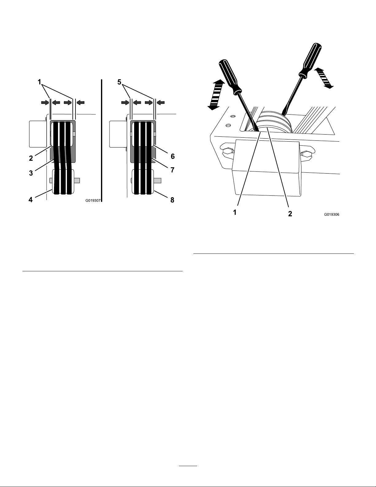
CheckingthePulleysandDriveBelts
G019307
4
7
1
2
3
5
6
8
G019306
1
2
1.Removethebeltguard;referto
RemovingtheBeltGuard(page33).
2.Checkthatthearborpulleyiscenteredinthe
openinginthebaseofthemachine.Ifthe
arborpulleyismisaligned,refertostep3in
AligningthePulleys(page36)(Figure49).
(Figure50).Ifthepulleyislooseonthearbor,
alignandsecurethepulley;refertostep3in
AligningthePulleys(page36).
Figure49
PulleyAlignment
1.Unequalspacingdistance5.Equalspacingdistance
2.Misalignedarborpulley6.Alignedarborpulley
3.Misaligneddrivebelts7.Aligneddrivebelts
4.Misaligneddrive-shaft
pulley
3.Checkpulleyalignmentbylookingatthesidesof
thebelts,eachshouldruninastraightlineoverand
betweeneachpulley(Figure49).Ifthebeltsand
pulleysaremisaligned,alignthepulleys;referto
AligningthePulleys(page36).
Note:Drivebeltmisalignmentisanindicationofa
pulley(s)thatarenotsecuretothearbororthedrive
shaftoftheengineorboth.
4.Checkthatthepulleysaresecureasfollows:
Note:Usemoderateforcewhencheckingthesecurity
ofthepulleys.Belttensionmayneedtobereduced
tocheckforaloosepulley .
A.Checkthatthedrive-shaftpulleyissecuretothe
engineshaftbygraspingthepulleyandpushit
towardtheengineandawayfromtheengine.If
thepulleyislooseonthedriveshaftoftheengine,
alignandsecurethepulley;refertostep5in
AligningthePulleys(page36).
8.Aligneddrive-shaftpulley
Figure50
LowerPulleyCheck
1.Lowerpulley
2.Openinginthebase
5.Checkthetensionofthedrivebeltsbydoingthe
following:
Note:Thebestdrivebelttensionforthemachineis
thelowesttensionatwhichthebeltswillnotslipunder
fullload.
A.Layastraightedgeoneachbeltandacrossthe
driveshaftandarborpulleys(Figure51).
B.Checkthatthearborpulleyissecuretothe
arborbypryingbetweentheopeninginthe
baseandendsofpulleywithascrewdriver
34
Page 35

G019310
1
2
Figure51
G01931 1
1
2
3
MeasuringBeltT ension
AdjustingtheDriveBeltTension
1.Removethebeltguard;referto
RemovingtheBeltGuard(page33).
2.Loosentheenginemountinghardwareasfollows:
•Model68045
A.Elevatethebladetoitshighestposition.
B.Loosenthebolts,washers,andnutsthat
securetheenginetothebaseofthemachine
Figure52).
(
1.Straightedge2.Deect5mmat2kg(.19
inchat4.2lb)
B.Withyournger,pushdownonthedrivebelt,
midwaybetweenthepulleys(Figure51).
Note:Checkthetensionofall3drivebelts.
C.Eachbeltshoulddeectapproximately5mm
at2kg(0.19inchat4.2lb)fromthestraight
edge(Figure51).Ifthebelttensionistoolow
ortoohigh,adjustthebelttension;referto
AdjustingtheDriveBeltTension(page35).
6.Installthebeltguard;referto
InstallingtheBeltGuard(page35).
7.Installthesparkplugwirepushingthewireontothe
terminaloftheplug.
InstallingtheBeltGuard
1.Alignthebeltguardoverthedrivebeltsandpulleys
andlowerittothebaseofthemachine.
2.Slidetheguardbacksothattherearangeoftheguard
isunderneaththeboltheadsattherearmounting
pointsoftheguard.
Figure52
BeltT ensioning(Model68045)
1.Tensionbolt3.Boltandnut
2.Jamnut
Note:Thenutsandwashersthatsecurethe
motorarelocatedatthebottomsideofthe
baseofthemachine.
•Model68046—Loosentheboltsandwashersthat
securetheengine-deckplatetothebaseofthe
machine(Figure53).
3.Securetheguardatthefrontmountingpoints
withtheboltsremovedduringstep
5in
RemovingtheBeltGuard(page33)
4.Tightentheboltsthatsecurethebeltguardtothebase
ofthemachineattherearmountingpoints.
35
Page 36

G019312
1
1
2
3
4
Figure53
1
2
3
G019313
BeltT ensioning(Model68046)
1.Bolt3.Jamnut
2.Tensionbolt4.Engine-deckplate
AligningthePulleys
1.Removethebeltguard;referto
RemovingtheBeltGuard(page33).
2.Reducethebelttension;refertoadjustthebelttension
instep4inAdjustingtheDriveBeltTension(page35).
3.Ifthearborpulleyismisalignedintheopeningofthe
baseofthemachineorlooseonthearbor(Figure49),
dothefollowing:
A.Pulltherecoilstarthandleoftheengineuntilthe
setscrewholeinthecenterV -beltgrooveofthe
pulleyisaccessible(Figure54).
3.Loosenthejamnutsthatsecurethetensionbolts
(Figure52andFigure53).
4.Adjustthebelttensionasfollows:
•Toincreasethebelttension,rotatethetension
Figure54
PulleySetScrew
boltclockwise.
•Toreducethebelttension,rotatethetensionbolt
counterclockwiseandslidetheengineforward.
1.Setscrewandcenter
V-beltgroove
2.Arborpulley
3.Belt
5.Checkthebelttension;refertostep5in
CheckingthePulleysandDriveBelts(page34).
Note:Ensurethatthepulleysarealignedandthe
engineisparallelwiththeframe(notangledtoward
theside).
6.Tightenthejamnutsforthetensionbolts.
7.Tightentheenginemountingboltsasfollows:
A.Model68045—Tightentheboltsandnutsthat
securetheenginetothebaseofthemachineto48
N-m(35ft-lb)(Figure52).
B.Loosenthesetscrew(Figure54).
C.Centerthealignmentofarborpulleyinthe
openingofthebaseofthemachinebyprying
betweentheopeninginthebaseandendsof
pulleywithascrewdriver.
D.Tightenthesetscrew(
Figure54).
4.Placeastraightedgeacrossthefaceofthedrive-shaft
pulleyandthearborpulley.Bothpulleysmustbe
alignedushwiththestraightedge(Figure55).
B.Model68046—Tightentheboltsthatsecurethe
enginedeckplatetothebaseofthemachineto48
N-m(35ft-lb)(
8.Installthebeltguard;referto
Figure53).
InstallingtheBeltGuard(page35).
9.Installthesparkplugwirepushingthewireontothe
terminaloftheplug.
36
Page 37

G019314
1
1
1
2
3
4
Drive-shaftPulleyAlignment
G019317
1
2
3
4
5
6
7
8
9
10
11
A.Whilesupportingthearborshaft,removethe
bolts,washers,andnutsthatsecurethearbor
bearingblockstothebottomsideofthebaseof
themachine(Figure56).
Figure55
1.Alignmentpoints
2.Straightedge
3.Drive-shaftpulley
4.Arborpulley
5.Ifthedrive-shaftpulleyisnotaligneddothefollowing:
A.Pulltherecoilstarthandleoftheengineuntilthe
setscrewholeinthecenterV -beltgrooveofthe
drive-shaftpulleyisaccessible.
B.Loosenthesetscrew .
C.Usingasoft-facemallet,tapthepulleyleftorright
alongthedriveshaftuntilthedrive-shaftpulley
andthearborpulleyarealignedtothestraight
Figure55).
edge(
D.Tightenthesetscrew.
E.Increasethebelttension;refertostep4in
AdjustingtheDriveBeltTension(page35)and
step5in
CheckingthePulleysandDriveBelts(page34)
6.Installthebeltguard;referto
InstallingtheBeltGuard(page35).
7.Installthesparkplugwirepushingthewireontothe
terminaloftheplug.
Figure56
B.Slipthebeltsoverthedriveshaftpulley
(Figure56).
C.Removethearborandbeltsfromthebaseofthe
machine(Figure56).
D.Removeanddiscardthedamagedorunserviceable
beltsfromthearborpulley.
7.Installthearborandbeltsasfollows:
A.Alignthenewbelts(orcombinationofnewand
serviceablebelts)overthearborpulley(
Figure56).
ReplacingtheDriveBelts
1.Elevatethebladetoitshighestposition;referto
AdjustingtheCuttingDepth(page14).
2.Ifinstalled,removethesawblade;referto
RemovingtheBlade(page12).
3.Removethebeltguard;referto
RemovingtheBeltGuard(page33).
4.Loosentheenginemountinghardwareasdescribedin
step2ofAdjustingtheDriveBeltTension(page35).
5.Loosenthebelttensionboltandjamnut,slidethe
engineforwardtoloosenbelts;refertoFigure52and
Figure53.
6.Removethebeltsasfollows:
beltsthroughthearborpulleyopeningandalign
thearborbearingblockstothemountingholes
inthebase(Figure56).
C.Securethearborbearingblockstothebasewith
thebolts,washersandnutsremovedinstep6-A.
D.Slipthebeltsoverthedrive-shaftpulley
(Figure56).
8.Checkthealignmentofthepulleys;referto
AligningthePulleys(page36).
9.Tensionthebelts;referto
AdjustingtheDriveBeltTension(page35).
10.Installthebeltguard;referto
InstallingtheBeltGuard(page35).
B.Frombeneaththebaseofthemachine,routethe
37
Page 38

SawBladeMaintenance
G019320
G019321
G019329
G019322
CheckingtheConditionandFunction
ServiceInterval:Beforeeachuseordaily—Checktheconditionofthesawbladeconditionforwearanddamage.
Important:Thewearandlossofthesaw-bladesegmentscansignicantlyimpairtheefciencyandperformanceof
themachine.Therefore,itisimportanttomakefrequentchecksoftheconditionofallofsegmentsandreplacethe
bladeifthesegmentsarewornexcessivelyordamaged.
Note:Amongthemostcriticalelementsofthemachineisthesawblade.Theyarealsothemostsubjecttowearanddamage.
Inthecourseofatsawingaproject-sitesurface,theynotonlymakecontactwiththeconcrete,asphalt,orboth,theyalso
encounterembeddedmetalobjects,suchasconcretewiremesh,rebar,andanchorbolts.
BladeTroubleshootingT able
SymptomPossibleCauseSolution
UnevenSegmentWear
CrackedSegments
WetCutting:insufcientwater(usuallyon
onesideoftheblade).
Equipmentdefects.Replacebadbearingsand/orwornarbor.
Cuttingheadmisaligned.Checkthatthesawbladealignmentis
Bond/matrixistoohardformaterialbeing
cut.
•Flushthewatersystem.
•Checkthewaterowtobothsidesofthe
blade.
Alignarbortothebaseofthemachine.
squareverticallyandhorizontally.
Installtheproperbladepertheblade
manufacturerrecommendation.
SegmentLoss
BladeWobbles
Bladeoverheatingduetoinadequate
coolant(waterorair).
Coreiswornfromundercutting.Seethetroubleshootingsymptomforblade
Bond/matrixistoohardformaterialbeing
cut.
Bladeiscuttingout-of-round,causinga
poundingmotion.
Bladeangesarenotthesamediameter
and/ortheangesaredamagedcausing
blademisalignment.
Blademountedonadamagedorworn
machine.
BladeoperatingimproperRPM.UseatachometertosetthebladeRPMto
Bladecollarsarenotthesamediameter.Replacethecollarsthatarenotidenticalin
Bladeisbentasaresultofdropping
twisting.
•WetCutting:Checkthewaterlines
tomakesureowis7.5–19liter/minute
(2–5gallon/minute)onbothsidesofthe
blade,andthattherearenoblockages.
•DryCutting:Runthebladefreeofthe
cutperiodicallytoaircool.
coreundercutting.
Installtheproperbladepertheblade
manufacturerrecommendation.
Replacebadbearings;alignthearbor;
replacewornbladecollars.
Replacethebladecollarthatarenot
identicalindiameterofthataredamaged.
Checkforbadarborbearings,loose
bearingblock,orbentarbor .
matchthespeciedRPMoftheblade.
diameterorthataredamaged.
Donotusethebentblade.Contactthe
blademanufacturer.
38
Page 39

BladeTroubleshootingTable(cont'd.)
G019323
G019328
G019324
G019325
G019326
G019327
BladeWillNotCut
CrackedCore
UndercuttingtheCore
Bond/matrixistoohardformaterialbeing
cut.
Bladehasbecomedull.
Failuretoinitiallybreak-inanewbladeon
thespecicmaterialbeingcut.
Bond/matrixistoohardformaterialbeing
cut.
Excessivecuttingpressure;jammingor
twistingthebladeinthecut.
Bladeoverheatingduetoinadequate
coolant(waterorair).
Abrasivewearingoffthecorefasterthan
thesegments.
Installtheproperbladepertheblade
manufacturerrecommendation.
Dressorsharpenbycuttingsofterabrasive
materialtoexposethediamonds.
Beak-inthebladeonthematerialtobecut.
Installtheproperbladepertheblade
manufacturerrecommendation.
Machineoperatorshouldusesteadyeven
feedpressureandbecarefultocutina
straightline.
•WetCutting:Checkthewaterlines
tomakesureowis7.5–19liter/minute
(2–5gallon/minute)onbothsidesofthe
blade,andthattherearenoblockages.
•DryCutting:Runthebladefreeofthe
cutperiodicallytoaircool.
•Usewatertoushthenes
thataregeneratedduringcutting.
•Useabladewithawear-retardantcore.
ArborHoleOut-of-round
BladeWornOut-of-round
LossofBladeTension
Bladecollarisnotproperlytightened.Wrenchtightenthearbornutandmake
certainthebladeisadequatelysecureto
preventrotation
Collarsaredirty.Cleantheinnerandoutercollars.Replace
ifwornordamaged.
Bladeisnotproperlyinstalled.Tightenthearbornutandcheckthatthe
drivepinisfunctioningproperly.
Arborbearingsworn.
Replacethearborbearingsand/orarboras
required.
Surgesoccurbecauseengineisnot
properlyadjusted.
Bladearborholeisdamagedfromblade
beingincorrectlyinstalled.
Bladeisslippingontheshaft.
Adjusttheengineaccordingtotheengine
Owner’sManual.
Replacethewornarborand/orcollars.
Replacethewornblade.
Tightenthearbornutandcollars,andcheck
thatthedrivepinisfunctioningproperly.
Bond/matrixistoohardformaterialbeing
cut.
Bladeusedismisalignedonthemachine.
Installtheproperbladepertheblade
manufacturerrecommendation.
Checkthatthesawbladealignmentis
squareverticallyandhorizontally.
Bond/matrixistoohardformaterialbeing
Useabladewithasofterbond/matrix.
cut.
Thecoreofthebladeisoverheating.Checkthewaterlinesandthewaterow
anddistribution.
ThebladeisrunningattheincorrectRPM.UseatachometertosetthebladeRPMto
matchthespeciedRPMoftheblade.
Thebladeisincorrectlymountedbetween
thecollars.
•Checkthatthedrivepinis
functioningproperly .
•Tightenthearbornut.
Thebladecollarsareundersizedornotthe
samediameter.
Replacethecollarsthatarenotthe
recommendedsizeorarenotidenticalin
diameter.
39
Page 40

Cleaning
Storage
CleaningtheMachine
Regularcleaningandwashingwillincreasethelifespanof
themachine.Cleanthemachineaftereachuse,beforethe
dirthardens.
Ensurethatthefueltankcapandoilcap/dipstickaresecure
toavoidgettingwaterinthetank.
Usecarewhenusingahigh-pressuresprayerbecauseitcan
damagewarningdecals,instructionsigns,andtheengine
Important:Lubricatethearborbearingsaftercleaning;
refertoGreasingtheMachine(page27).
StoringtheMachine
Forstorageover30days,preparetheunitasfollows:
1.Removedirtandgrimefromtheexternalpartsof
theentireunit,especiallytheengine.Cleandirtand
sawdustchipsfromtheoutsideoftheenginecylinder
headnsandblowerhousing.
Important:Y oucanwashtheunitwithmild
detergentandwater.
2.Conditionthefuelsystemasfollows:
A.Addapetroleumbasedstabilizer/conditionerto
fuelinthetank.Followmixinginstructionsfrom
stabilizermanufacturer.(1oz.perUSgallon).
Donotuseanalcoholbasedstabilizer(ethanol
ormethanol).
Important:Donotstore
stabilizer/conditionedgasolineover90
days.
Note:Fuelstabilizer/conditionerismost
effectivewhenmixedwithfreshgasolineandused
atalltimes.
B.Runtheenginetodistributeconditionedfuel
throughthefuelsystem(5minutes).
C.Stoptheengine,allowittocool,anddrainthe
fueltankusingapumptypesiphon.Disposeof
fuelproperly;recycleasperlocalcodes.
D.Starttheengineandrunituntilitstops.
E.Choketheengine.
F.Startandruntheengineuntilitwillnotstartagain.
3.Cleanthesedimentcup;referto
CleaningtheSedimentCup(page30).
4.Servicetheaircleaner;referto
ServicingtheAirFilter(page28).
5.Changetheenginecrankcaseoil;referto
ChangingtheEngineOil(page29).
6.Removethesparkplugandcheckthecondition;refer
toServicingtheSparkPlug(page31).
7.Conditiontheengineasfollows:
A.Removethesparkplugandpourtwotablespoons
ofengineoilintothesparkplughole;referto
RemovingtheSparkPlug(page31).
B.Pulltherecoilstarthandleslowlytocrankthe
engineanddistributetheoilinsidethecylinder.
C.Installthesparkplug;referto
InstallingtheSparkPlug(page32).
Note:Donotinstallthewireonthesparkplug.
8.Greasethebearingsforthearborandrearwheel
andlubricatethethreadsofthebladeelevation
40
Page 41

screw;refertoGreasingtheMachine(page27)and
LubricatetheElevationScrew(page27).
9.Checkandtightenallbolts,nuts,andscrews.Repairor
replaceanypartthatisdamaged.
10.Paintallscratchedorbaremetalsurfaces.Paintis
availablefromyourAuthorizedServiceDealer.
11.Storetheunitinaclean,drygarageorstoragearea.
12.Covertheunittoprotectitandkeepitclean.
41
Page 42

Troubleshooting
Note:SawswiththeHondaGXseriesenginesareequippedwiththeOilAlert®System.
OilAlert®isaregisteredtrademarkofHONDAGIKENKOGYOKABUSHIKIKAISHACORPORATION.
Theenginewillnotstart.
Problem
1.Ontheoperatorpanel,theengine
switchisintheStopposition
2.ThefuelvalveisOff.2.Movethefuel-valvelevertotheOn
3.Thechokeisclosed
4.Thechokeisopen.
5.Ontheengine,On/Offswitchisinthe
Offposition.
6.Theengineoillevelislow(OilAlert
modelengines)
7.Thefueltankisempty.7.Filltankwithfreshfuel.
8.Badfuel:enginestoredwithouttreating
ordrainingthegasoline,orrefueled
withbadgasoline.
9.Thesparkplugisfouledorimproperly
gapped.
10.Thesparkplugiswetwithfuel(ooded
engine).
11.Thesparkplugwireislooseor
disconnected.
PossibleCauseCorrectiveAction
1.PresstheengineswitchtotheRun
position.
position.
3.Openthechokewhenstartingahot
engine.
4.Closethechokewhenstartingacold
engine.
5.RotatetheswitchtotheOnposition.
6.Fillwiththerecommendedoiltothe
properlevel.
8.Drainthefueltankandcarburetor.
Refuelwithfreshgasoline.
9.Gaporreplacethesparkplug.
10.Removethesparkplug,dryit,and
installtheplug.Starttheenginewith
thethrottleintheMAXposition.
11.Removethesparkplugwire,cleanthe
sparkplugterminalandtheterminal
socketinbootofthesparkplugwire,
andreinstallthesparkplugwire.
Theenginelackspowerorrunsrough.
Thebeltslipsorcomesoffthepulleys.
1.Theairlterisrestricted.1.Cleanorreplacetheairlterelement(s).
2.Badfuel:enginestoredwithouttreating
ordrainingthegasoline,orrefueled
withbadgasoline.
3.Thereiswaterorcontaminantsinthe
fuel.
4.Thefuellineisrestricted.4.Cleanthefuellterandsedimentcup.
5.Thechokeislefton.5.Openthechoke.
6.Thesparkplugsarewornorhave
buildupontheelectrodes.
7.Toomuchoilintheenginecrankcase.7.Draintheoiltotheproperlevel.
1.Thebelttensionisinsufcient.
2.Thebeltisworn.2.Replacethebelt.
3.Thepulley(s)areworn.3.ContactyourAuthorizedService
4.Thepulley(s)aremisaligned.4.Alignthepulley(s).
2.Drainthefueltankandcarburetor.
Refuelwithfreshgasoline.
3.Drainthefueltankandcarburetor.
Refuelwithfreshgasoline.
6.Checktheelectrodegapandcleanor
replacethesparkplug.
1.Adjustthebelttension.
Dealer.
42
Page 43

Notes:
43
Page 44

Alimitedwarranty(seewarrantyperiodsbelow)
TheToroWarranty
Concrete,Masonry,
andCompaction
Equipment
ConditionsandProductsCovered
TheT oroCompanyanditsafliate,T oroWarrantyCompany,pursuantto
anagreementbetweenthem,jointlywarrantyourT oroConcrete,Masonry ,
andCompactionEquipmentProductslistedbelowtobefreefromdefects
inmaterialsorworkmanship.
Thiswarrantycoversthecostofpartsandlabor,butyoumustpay
transportationcosts.
Thefollowingtimeperiodsapplyfromthedateofpurchase:
ProductsWarrantyPeriod
ConcreteMixers
•SpindleBearingsLifetime*(originalowneronly)
MortarMixers1year
•DrumBearingsandSealsLifetime*(originalowneronly)
ForwardPlateCompactors
ReversiblePlates1year
RammerCompactors
MudBuggy1year
VibratingTrenchRoller2years
ConcreteSaws
MasonrySaws
PowerTrowels1year
Screeds
ConcreteVibrators
Whereawarrantableconditionexists,wewillrepairtheProductatnocost
toyouincludingdiagnosis,labor,andparts.
*
LifetimeWarranty-Ifthebearing(s)orseal(s)onyourmixerfail,itwillbereplacedunderwarranty,
atnocostforpartsorlabor.
1year
2years
2years
1year
1year
1year
1year
InstructionsforObtainingWarrantyService
IfyouthinkthatyourT oroProductcontainsadefectinmaterialsor
workmanship,followthisprocedure
1.ContactanyAuthorizedServicingOutlettoarrangeserviceattheir
dealership.Tolocateoneconvenienttoyou,accessourwebsiteat
www.T oro.com.Select“WheretoBuy”andselect“Contractor”under
producttype.Y oumayalsocallourtollfreenumberbelow.
2.Bringtheproductandyourproofofpurchase(salesreceipt)tothem.
3.IfforanyreasonyouaredissatisedwiththeServiceOutlet’s
analysisorwiththeassistanceprovided,contactusat:
SWSCustomerCareDepartment
ToroWarrantyCompany
811 1LyndaleAvenueSouth
Bloomington,MN55420-1 196
TollFree:800-888-9926
**
ToroAuthorizedRentalCustomerswhohavepurchasedproductsdirectlyfromToroandhave
signedtheToroRentalCustomerAgreementhavetheabilitytoperformtheirownwarrantywork.
PleasevisitToro’ sRentalPortalforelectronicwarrantyclamlingproceduresorcallthetollfree
numberabove.
**
:
OwnerResponsibilities
YoumustmaintainyourT oroProductbyfollowingthemaintenance
proceduresdescribedintheOperator’sManual.Suchroutine
maintenance,whetherperformedbyadealerorbyyou,isatyourexpense.
Partsscheduledforreplacementasrequiredmaintenance(“Maintenance
Parts”),arewarrantedfortheperiodoftimeuptothescheduled
replacementtimeforthatpart.Failuretoperformrequiredmaintenance
andadjustmentscanbegroundsfordisallowingawarrantyclaim.
ItemsandConditionsNotCovered
Notallproductfailuresormalfunctionsthatoccurduringthewarranty
periodaredefectsinmaterialsorworkmanship.Thisexpresswarranty
doesnotcoverthefollowing:
•Productfailureswhichresultfromtheuseofnon-Tororeplacement
parts,orfrominstallationanduseofadd-on,modied,orunapproved
accessories
•Productfailureswhichresultfromfailuretoperformrequired
maintenanceand/oradjustments
•ProductfailureswhichresultfromoperatingtheProductinan
abusive,negligentorrecklessmanner
•Partssubjecttoconsumptionthroughuseunlessfoundtobe
defective.Examplesofpartswhichareconsumed,orusedup,during
normalproductoperationinclude,butarenotlimitedto,belts,wipers,
sparkplugs,tires,lters,gaskets,wearplates,seals,O-rings,drive
chains,clutches.
•Failurescausedbyoutsideinuence.Itemsconsideredtobeoutside
inuenceinclude,butarenotlimitedto,weather,storagepractices,
contamination,useofunapprovedcoolants,lubricants,additives,or
chemicals,etc.
•Normal“wearandtear”items.Normal“wearandtear”includes,butis
notlimitedto,wornpaintedsurfaces,scratcheddecals,etc.
•Anycomponentcoveredbyaseparatemanufacturer’swarranty
•Pickupanddeliverycharges
GeneralConditions
RepairbyanAuthorizedServicingOutletorSelf-ServiceasanAuthorized
RentalCustomerisyoursoleremedyunderthewarranty.
NeitherTheToroCompanynorToroWarrantyCompanyisliablefor
indirect,incidentalorconsequentialdamagesinconnectionwith
theuseoftheToroProductscoveredbythiswarranty ,including
anycostorexpenseofprovidingsubstituteequipmentorservice
duringreasonableperiodsofmalfunctionornon-usepending
completionofrepairsunderthiswarranty.Allimpliedwarranties
ofmerchantabilityandtnessforusearelimitedtotheduration
ofthisexpresswarranty.Somestatesdonotallowexclusionsof
incidentalorconsequentialdamages,orlimitationsonhowlong
animpliedwarrantylasts,sotheaboveexclusionsandlimitations
maynotapplytoyou.
Thiswarrantygivesyouspeciclegalrights,andyoumayalsohaveother
rightswhichvaryfromstatetostate.
ExceptfortheenginewarrantycoverageandtheEmissionswarranty
referencedbelow,ifapplicable,thereisnootherexpresswarranty .The
EmissionsControlSystemonyourProductmaybecoveredbyaseparate
warrantymeetingrequirementsestablishedbytheU.S.Environmental
ProtectionAgency(EPA)ortheCaliforniaAirResourcesBoard(CARB).
RefertotheCaliforniaEmissionControlWarrantyStatementsuppliedwith
yourProductorcontainedintheenginemanufacturer’sdocumentationfor
details.
CountriesOtherthantheUnitedStatesorCanada
CustomerswhohavepurchasedT oroproductsoutsidetheUnitedStatesorCanadashouldcontacttheirT oroDistributor(Dealer)toobtainguarantee
policiesforyourcountry,province,orstate.IfforanyreasonyouaredissatisedwithyourDistributor'sserviceorhavedifcultyobtainingguarantee
information,contacttheT oroimporter.Ifallotherremediesfail,youmaycontactusatT oroWarrantyCompany.
AustralianConsumerLaw:AustraliancustomerswillnddetailsrelatingtotheAustralianConsumerLaweitherinsidetheboxoratyourlocalT oro
Dealer.
374-0288RevB
 Loading...