

Page 1
FormNo.3377-557RevB
1
G021551
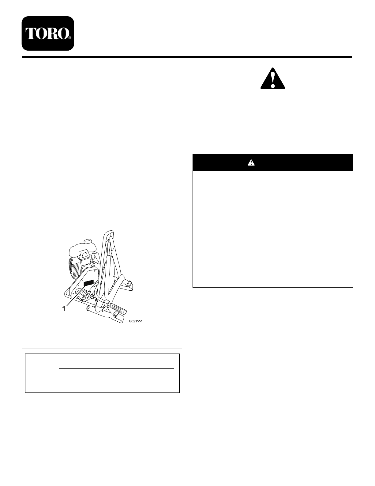
VIB-2.5BPConcreteVibrator
ModelNo.68043—SerialNo.313000001andUp
Operator'sManual
Introduction
Thisconcretevibratorisdesignedforvibratingand
consolidatingconcreteproductsbyremovingairpocketsand
voids.
Readthisinformationcarefullytolearnhowtooperateand
maintainyourproductproperlyandtoavoidinjuryand
productdamage.Youareresponsibleforoperatingthe
productproperlyandsafely.
YoumaycontactTorodirectlyatwww .Toro.comforproduct
andaccessoryinformation,helpndingadealer,ortoregister
yourproduct.
Wheneveryouneedservice,genuineT oroparts,oradditional
information,contactanAuthorizedServiceDealerorToro
CustomerServiceandhavethemodelandserialnumbersof
yourproductready.Figure1identiesthelocationofthe
modelandserialnumbersontheproduct.Writethenumbers
inthespaceprovided.
Figure2
1.Safetyalertsymbol
Thismanualuses2wordstohighlightinformation.
Importantcallsattentiontospecialmechanicalinformation
andNoteemphasizesgeneralinformationworthyofspecial
attention.
WARNING
CALIFORNIA
Proposition65Warning
Thisproductcontainsachemicalorchemicals
knowntotheStateofCaliforniatocausecancer,
birthdefects,orreproductiveharm.
Theengineexhaustfromthisproduct
containschemicalsknowntotheStateof
Californiatocausecancer,birthdefects,
orotherreproductiveharm.
Useofthisproductmaycauseexposureto
chemicalsknowntotheStateofCalifornia
tocausecancer,birthdefects,orother
reproductiveharm.
ThissparkignitionsystemcomplieswithCanadianICES-002.
Becauseinsomeareastherearelocal,state,orfederal
Figure1
1.Modelandserialnumberlocation
regulationsrequiringthatasparkarresterbeusedonthe
engineofthismachine,asparkarresterisavailableas
anoption.Ifyourequireasparkarrester,contactyour
AuthorizedToroServiceDealer.
GenuineTorosparkarrestersareapprovedbytheUSDA
ModelNo.
ForestryService.
Important:ItisaviolationofCaliforniaPublic
SerialNo.
ResourceCodeSection4442touseoroperatetheengine
onanyforest-covered,brush-covered,orgrass-covered
Thismanualidentiespotentialhazardsandhassafety
messagesidentiedbythesafetyalertsymbol(Figure2),
whichsignalsahazardthatmaycauseseriousinjuryordeath
ifyoudonotfollowtherecommendedprecautions.
landwithoutasparkarrestermufermaintainedin
workingorder,ortheengineconstricted,equipped,and
maintainedforthepreventionofre.Otherstatesor
federalareasmayhavesimilarlaws.
Theenclosed
Engine Owner's Man ual
issuppliedfor
informationregardingtheUSEnvironmentalProtection
Agency(EPA)andtheCaliforniaEmissionControl
©2013—TheT oro®Company
8111LyndaleAvenueSouth
Bloomington,MN55420
Registeratwww.T oro.com.
OriginalInstructions(EN)
PrintedintheUSA
AllRightsReserved
*3377-557*B
Page 2

Regulationofemissionsystems,maintenance,and
warranty.Replacementsmaybeorderedthroughthe
enginemanufacturer.
SafeOperatingPractices
Alwaysfollowallsafetyinstructionstoavoidseriousinjury
ordeath.
Contents
Introduction..................................................................1
SafeOperatingPractices...........................................2
SafetyandInstructionalDecals.................................4
Setup............................................................................5
1FillingtheEnginewithOil......................................5
2InstallingtheThrottleArm.....................................6
ProductOverview..........................................................7
Controls................................................................8
Specications.........................................................9
Operation.....................................................................9
ReadtheInstructionManual.....................................9
Attachments/Accessories.........................................9
AddingFuel............................................................9
CheckingtheEngineOilLevel.................................11
InstallingtheHeadontotheShaft.............................11
RemovingtheHeadfromtheShaft...........................13
ConnectingtheShafttotheMachine.........................14
StartingandStoppingtheEngine..............................14
UsingtheMachine..................................................14
OperatingTips......................................................15
Maintenance.................................................................16
RecommendedMaintenanceSchedule(s)......................16
PreparingtheMachineforMaintenance.....................16
LubricatingtheShaft...............................................16
ServicingtheAirCleaner.........................................17
ChangingtheEngineOil.........................................17
ServicingtheSparkPlug..........................................18
ServicingtheSparkArrester.....................................20
ServicingtheFuelSystem........................................20
ServicingtheBelt...................................................21
Storage........................................................................22
PreparingtheMachineforStorage............................22
Troubleshooting...........................................................23
Safety
Improperlyusingormaintainingthemachinecanresult
ininjury.T oreducethepotentialforinjury,complywith
thesesafetyinstructionsandalwayspayattentiontothe
safetyalertsymbol(Figure2)whichmeansCaution,
Warning,orDanger—personalsafetyinstruction.
Failuretocomplywiththeinstructionmayresultin
personalinjuryordeath.
WARNING
Engineexhaustcontainscarbonmonoxide,an
odorless,deadlypoisonthatcankillyou.
Donotruntheengineindoorsorinanenclosed
area.
Training
•ReadtheOperator'sManualandothertrainingmaterial.If
theoperator(s)ormechanic(s)cannotreadorunderstand
theinformation,itistheowner'sresponsibilitytoexplain
thismaterialtothem.
•Becomefamiliarwiththesafeoperationoftheequipment,
operatorcontrols,andsafetysigns.
•Alloperatorsandmechanicsshouldbetrained.The
ownerisresponsiblefortrainingtheusers.
•Neverletchildrenoruntrainedpeopleoperateorservice
theequipment.Localregulationsmayrestricttheageof
theoperator.
•Theowner/usercanpreventandisresponsiblefor
accidentsorinjuriestopeopleordamagetoproperty.
Preparation
Becomefamiliarwiththesafeoperationoftheequipment,
operatorcontrols,andsafetysigns.
•Useonlyaccessoriesandattachmentsapprovedbythe
manufacturer.
•Wearpersonalprotectiveequipmentandappropriate
clothingincluding:
–safetyglasses
–hearingprotection
–safetyshoes
–longpants
–shirtwithlongsleevesthataretightatthewrists
–tight-ttinggloveswithoutdrawstringsorloosecuffs
•Securelonghair,looseclothing,orjewelrythatmayget
tangledinmovingparts.
•Operatingtheequipmentsafelyrequiresthefullattention
oftheoperator.Donotwearradioormusicheadphones
whileoperatingthemachine.
•Useextracarewhenhandlingfuels.Theyareammable
andthevaporsareexplosive.Usethefollowingpractices
whenhandlingfuel:
–Useonlyanapprovedfuelcontainer.
–Neverremovethefuelcaporaddfuelwiththeengine
running.
–Allowtheenginetocoolbeforerefueling.
–Donotsmoke.
2
Page 3

–Neverrefuelordrainthemachineindoors.
MaintenanceandStorage
–Replacethefuelcapandtightenitsecurely.
–Keepthecontainernozzleincontactwiththetank
duringlling.
–Neverllacontainerwhileitisinsideavehicle,trunk,
pick-upbed,oranysurfaceotherthantheground.
–Neverstorethemachineorfuelcontainerinside
wherethereisanopename,suchasnearawater
heaterorfurnace.
–Iffuelisspilled,wipeitofftheengineandequipment.
Operation
•Neverrunanengineinanenclosedorpoorlyventilated
area.
•Onlyoperatethemachineingoodlightingconditions.
•Beforestartingthemachine,makesurethatthereareno
personsorobstaclesnearorunderthemachine.
•Shutofftheenginebeforeleavingthemachineforany
reason.Neverleavearunningmachineunattended.
Alwaysstoptheengineandverifythatallmovingparts
havestopped.
•Avoidprolongedbreathingofexhaustfumes.Engine
exhaustfumescancausesicknessordeath.
•Donotoperatethemachineundertheinuenceof
alcoholordrugs.
•Donottouchpartswhichmaybehotfromoperation.
Allowthemtocoolbeforeattemptingtomaintain,adjust,
orservicethemachine.
•Ensurethatalltheguardsandshieldsaresecurelyinplace
beforeoperatingthemachine.
•Beforeperformingmaintenance,dothefollowing:
–Placethemachineonlevelground.
–Stoptheengine.Waitforallmovementtostopbefore
adjusting,cleaning,orrepairingthemachine.
–Lettheenginecoolbeforeperformingmaintenance
orstoringthemachine.
–Disengageallpowerandoperationcontrols.
•Donotlubricate,service,orrepairthemachinewhileitis
running.
•Keepequipmentmaterialsclearfromthemuferand
enginetohelppreventres.Cleanupanyoilorfuel
spillage.
•Neverallowuntrainedpersonneltoservicethemachine.
•Keephands,feet,andclothingawayfrommovingparts.
Ifpossible,donotmakeadjustmentswiththeengine
running.
•Keepallpartsingoodworkingconditionandallhardware
tightened.Replaceallwornordamageddecals.
•Removeanybuildupofgrease,oil,ordebrisfromthe
machine.
•Stopandinspectthemachineifaforeignobjectcausesan
obstruction.Makeanynecessaryrepairsbeforestarting
themachine.
•Donottamperwithsafetydevices.
•Keepallnuts,bolts,screws,andhoseclampssecurely
tightened.Keepequipmentingoodcondition.
•UseonlygenuineTororeplacementpartstoensurethat
theoriginalstandardsaremaintained.
•Ifthemachinestrikesaforeignobjectorifthemachine
startsmakinganunusualnoiseorvibration,stopthe
engine.Waitforallmovingpartstocometoacomplete
stopandcool.Vibrationisgenerallyawarningoftrouble.
Inspectforcloggingordamage.Cleanandrepairand/or
replacedamagedparts.
•Donotchangetheenginegovernorsettingoroverspeed
theengine.
•Lightningcancausesevereinjuryordeath.Ifyousee
lightningorhearthunderinthearea,donotoperatethe
machine;seekshelter.
3
Page 4
SafetyandInstructional
Decals
Important:Safetyandinstructiondecalsarelocated
nearareasofpotentialdanger.Replacedamageddecals.
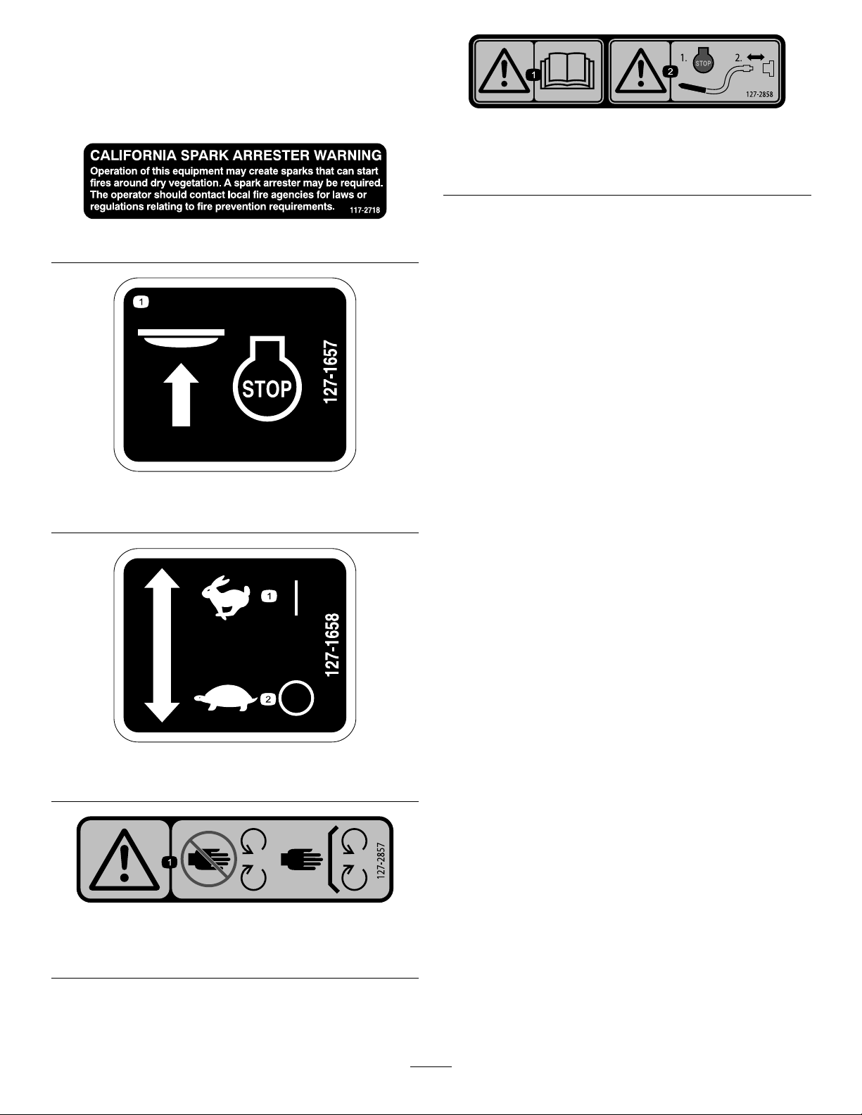
127–2858
1.Pushtostoptheengine.
1.Warning—readthe
Operator’sManual.
117–2718
127–1657
2.Warning—1)Stopthe
engine;2)Disconnectthe
shaft.
127–1658
1.Fast—on
1.Warning—keepawayfrommovingparts;keepallguards
andsafetiesinplace.
2.Slow—off
127–2857
4
Page 5
Setup
G021529
3
4
G0 215 30
1
2
1
FillingtheEnginewithOil
NoPartsRequired
Procedure
Important:Use4-cycleengineoilthatmeetsorexceeds
therequirementsforAPIservicecategory
or higher
Crankcasecapacity:0.25L(0.26USqt)
Important:Iftheoillevelinthecrankcaseistoolow
ortoohighandyouruntheengine,youmaydamage
theengine.Thistypeofdamageisnotcoveredbythe
warranty.
.
SJ , SL, SM,
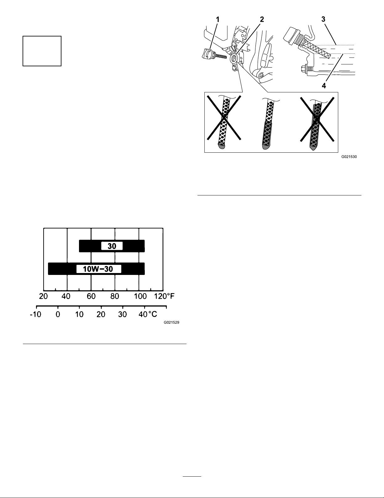
Figure4
1.Oilllhole3.Oil-levelupperlimit
2.Dipstick
4.Oil-levellowerlimit
Note:UseSAE10W-30forgeneraluse.YoucanuseSAE
30whentheaveragetemperatureinyourareaiswithinthe
indicatedrange(Figure3).
Figure3
1.Removethedipstick(Figure4)andslowlypouroilinto
thellholeuntiltheoilreachestheupper-limitmark
(bottomedgeoftheoil-llhole)onthedipstick.
2.Replaceandsecurethedipstick.
3.Wipeupanyspilledoil.
5
Page 6
2
G021558
1
2
4
3
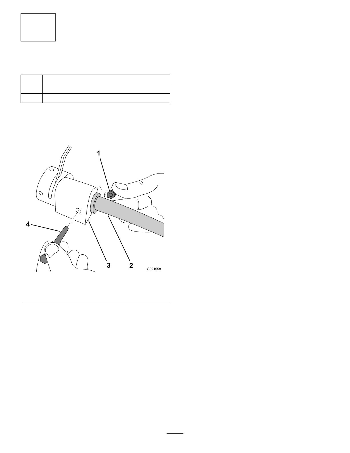
InstallingtheThrottleArm
Partsneededforthisprocedure:
1Throttlearm
1Bolt
1Locknut
Procedure
1.Aligntheinnercoreofthehandlewiththecoreadapter
onthethrottlecontrolbox(Figure5),andinsertitfully.
Figure5
1.Locknut3.Throttlecontrolbox
2.Throttlearm4.Bolt
Note:Ensurethattheatareaonthetubeisonthe
bottom.
2.Inserttheboltthroughthethrottlecontrolbox,and
secureitwiththelocknut(
3.Connectthemaleelectricalconnectorfromtheengine
switchonthethrottlearmtothefemaleconnectoron
theengine.
Note:Ensurethattheconnectorsareconnected
securely.
Figure5).
6
Page 7
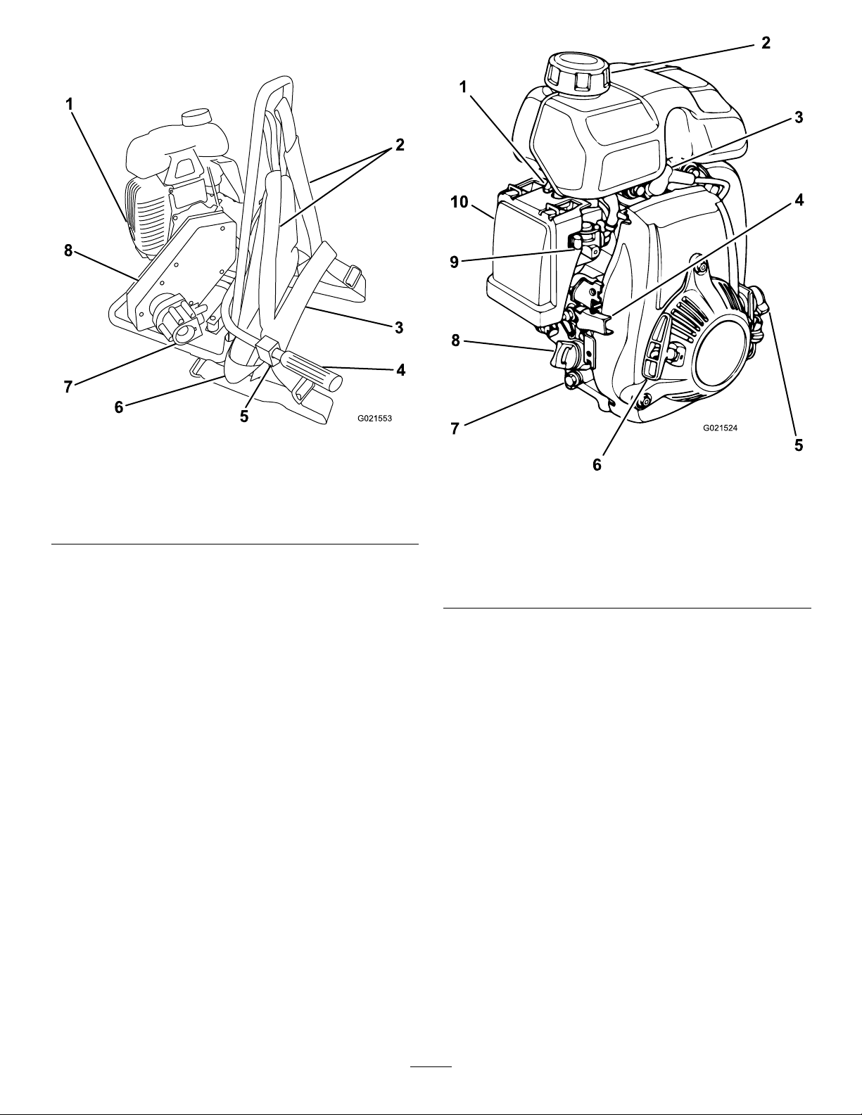
ProductOverview
G021553
1
2
3
4
7
8
6
5
1
2
4
6
7
8
10
5
9
3
G021524
Figure6
1.Mufer
2.Shoulderstraps
3.Cheststrap7.Shaftcoupling
4.Throttlegrip8.Beltguard
5.Enginestopbutton
6.Waiststrap
Figure7
1.Chokelever
2.Fuelcap
3.Spark-plugwire
4.Throttle9.Fuelvalve
5.On/Offswitch
6.Recoil-starthandle
7.Oildrainplug
8.Dipstick
10.Aircleaner
7
Page 8
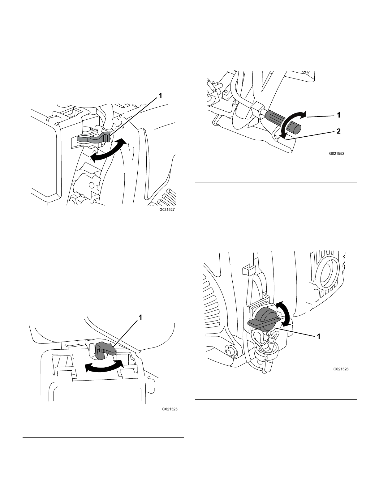
Controls
G021527
1
1
G021525
G021552
2
1
G021526
1
FuelValve
Thefuelvalve(Figure8)islocatedtotherightofandbelow
thechokelever.MovetheleverforthefuelvalvetotheOn
positionbeforeattemptingtostarttheengine.Whenyou
havenishedusingthemachine,stoptheengineandmove
thefuelvalvelevertotheOffposition.
ThrottleGrip
Thethrottlelever(Figure10)controlsthespeed(rpm)ofthe
engine.Itislocatedattheendofthethrottlearm.Itsets
theenginespeedandthereforecanincreaseanddecreasethe
vibrationspeedofthehead.Forbestperformance,setthis
controltothefastpositionwhenusingthemachine.
Figure10
Figure8
1.Fuelvalve
ChokeLever
Usethechokelever(Figure9)tostartacoldengine.Before
pullingtherecoil-starthandle,movethechokelevertothe
closedposition(right).Oncetheengineisrunning,movethe
chokelevertotheopenposition(left).Donotusethechoke
iftheengineisalreadywarmeduportheairtemperatureis
high.
1.Slow(idle)
2.Fast
EngineOn/OffSwitch
TheOn/Offswitch(Figure11)allowstheoperatorofthe
machinetostartandstoptheengine.RotatetheOn/Off
switchtotheOnposition(clockwise)tostartandrunthe
engine.RotatetheOn/OffswitchtotheOffposition
(counterclockwise)tostoptheengine.
1.Chokelever
Figure9
1.On/Offswitch
Figure11
Recoil-startHandle
Tostarttheengine,pulltherecoil-starthandle(Figure7)
quickly.Ensurethattheenginecontrolsdescribedaboveare
allsetcorrectly.
8
Page 9

EngineStopButton
G021593
1
G0 231 52
Theenginestopbutton(Figure12)islocatedunderthe
throttlearmandnearthethrottlegrip.Pressitifyouneedto
stoptheenginequickly.
Operation
ReadtheInstructionManual
Figure13
Symbollocatedonthenon-serviceableserial-numberplate
Figure12
1.Enginestopbutton
Oil-levelSwitch
Theoil-levelswitchislocatedinsidetheengine,anditwillnot
allowtheenginetorunwhentheoillevelisbelowthesafe
operatinglimit.
Specications
WeightLengthWidthHeight
5.5kg
(12.1lb)
33cm
(13inches)
34.9cm
(14inches)
58.4cm
(23inches)
1.Warning–T oreducetheriskofinjury ,usermustreadand
understandtheinstructionmanual.
Attachments/Accessories
AselectionofToroapprovedattachmentsandaccessoriesis
availableforusewiththemachinetoenhanceandexpand
itscapabilities.ContactyourAuthorizedServiceDealeror
Distributororgotowww .Toro.comforalistofallapproved
attachmentsandaccessories.
AddingFuel
•Forbestresults,useonlyclean,fresh,unleadedgasoline
withanoctaneratingof87orhigher((R+M)/2rating
method).
•Oxygenatedfuelwithupto10%ethanolor15%MTBE
byvolumeisacceptable.
•Donotuseethanolblendsofgasoline(suchasE15
orE85)withmorethan10%ethanolbyvolume.
Performanceproblemsand/orenginedamagemayresult
whichmaynotbecoveredunderwarranty.
•Donotusegasolinecontainingmethanol.
•Donotstorefueleitherinthefueltankorfuelcontainers
overthewinterunlessitcontainsafuelstabilizer.
•Donotaddoiltogasoline.
9
Page 10

DANGER
1
2
G021528
WARNING
Incertainconditions,fuelisextremelyammable
andhighlyexplosive.Areorexplosionfromfuel
canburnyouandothersandcandamageproperty.
•Fillthefueltankoutdoors,inanopenarea,when
theengineiscold.Wipeupanyfuelthatspills.
•Neverllthefueltankinsideanenclosedtrailer.
•Donotllthefueltankcompletelyfull.Add
fueltothefueltankuntilthelevelisnohigher
thanthescreenonthelterinthefueltank.
Thisemptyspaceinthetankallowsthefuelto
expand.
•Neversmokewhenhandlingfuel,andstayaway
fromanopenameorwherefuelfumesmaybe
ignitedbyaspark.
•Storefuelinanapprovedcontainerandkeepit
outofthereachofchildren.Neverbuymore
thana30-daysupplyoffuel.
•Donotoperatewithouttheentireexhaust
systeminplaceandinproperworkingcondition.
Fuelisharmfulorfatalifswallowed.Long-term
exposuretovaporscancauseseriousinjuryand
illness.
•Avoidprolongedbreathingofvapors.
•Keepyourfaceawayfromthenozzleandthe
fueltankorconditioneropening .
•Keepfuelawayfromyoureyesandskin.
Important:Donotmixoilwithfuel.
RecommendedFuel
UnleadedGasoline
U.S.
Except
U.S.
Pumpoctanerating87orhigher
Researchoctanerating92orhigher
Pumpoctanerating87orhigher
UsingFuelStabilizer/Conditioner
Useafuelstabilizer/conditionerinthemachinetokeepthe
fuelfreshduringstorageof90daysorless.Ifyouarestoring
themachineforlonger,drainthefueltank;refertoDraining
theFuelTankandCarburetor(page20).
DANGER
Incertainconditionsduringfueling,static
electricitycanbereleased,causingasparkwhich
canignitethefuelvapors.Areorexplosionfrom
fuelcanburnyouandothersandcandamage
property.
•Alwaysplacefuelcontainersonthegroundaway
fromyourvehiclebeforelling .
•Donotllfuelcontainersinsideavehicleoron
atruckortrailerbedbecauseinteriorcarpets
orplastictruckbedlinersmayinsulatethe
containerandslowthelossofanystaticcharge.
•Whenpractical,removefuel-poweredequipment
fromthetruckortrailerandfueltheequipment
ontheground.Ifthisisnotpossible,then
fuelsuchequipmentonatruckortrailerfrom
aportablecontainerratherthanfromafuel
dispensernozzle.
•Ifyoumustuseafueldispensernozzle,keepthe
nozzleincontactwiththerimofthefueltank
orcontaineropeningatalltimesuntilfuelingis
complete.
Important:Donotusefueladditivescontaining
methanolorethanol.
Addthecorrectamountoffuelstabilizer/conditionertothe
fuel,andfollowthedirectionsofthemanufacturer.
Note:Fuelstabilizer/conditionerismosteffectivewhen
mixedwithfreshfuel.Tominimizethechanceofvarnish
depositsinthefuelsystem,usefuelstabilizeratalltimes.
FillingtheFuelTank
Capacity:0.77L(0.20USgallon)
1.Placethemachineonalevelsurface,stoptheengine,
andallowtheenginetocool;refertoStoppingthe
Engine(page14).
2.Cleanaroundthefuelcap,andremoveit.
1.Fuel-levelmark
Figure14
2.Maximumfuellevel
10
Page 11

3.Addunleadedgasolinetothefueltank,untilthelevelis
G021529
3
4
G0 215 30
1
2
atthefuel-levelmark,asshowninFigure14.
Important:Thisspaceinthetankallowsthefuel
toexpand.Donotllthefueltankcompletelyfull.
4.Installthefuelcapsecurely(Figure14).
5.Wipeupanyfuelthatmayhavespilled.
CheckingtheEngineOilLevel
ServiceInterval:Beforeeachuseordaily
Important:Use4-cycleengineoilthatmeetsorexceeds
therequirementsforAPIservicecategory
or higher
Crankcasecapacity:0.25L(0.26USqt)
Important:Iftheoillevelinthecrankcaseistoolow
ortoohighandyouruntheengine,youmaydamage
theengine.Thistypeofdamageisnotcoveredbythe
warranty.
Note:UseSAE10W-30forgeneraluse.YoucanuseSAE
30whentheaveragetemperatureinyourareaiswithinthe
indicatedrange(
.
Figure15).
SJ , SL, SM,
Figure16
1.Fillport
2.Dipstick
5.Slidethedipstickfullyintothellportwithout
threadingitintotheport(Figure16).
3.Oil-levelupperlimit
4.Oil-levellowerlimit
Figure15
1.Placethemachineonaat,levelsurface,andstopthe
engine;refertoStoppingtheEngine(page14).
2.Allowtheenginetocool.
3.Cleanaroundthedipstick.
4.Removethedipstickandwipetheendclean(Figure16).
6.Removethedipstickandlookattheend.Iftheengine
oillevelislow ,slowlypouronlyenoughoilintothell
porttoraisetheleveltotheFullmarkonthedipstick
(Figure16).
Note:T oroPremiumEngineOilisavailablefrom
yourAuthorizedToroDealer.
7.Replaceandsecurethedipstick(Figure16).
InstallingtheHeadontothe Shaft
Note:Theheadandshaftaresoldseparately.Thereisa
varietyofsizesavailablefromyourAuthorizedT oroDealer.
1.Holdthethreadedendoftheshaftinapipevise,and
coatthethreadsoftheshaftwithathreadsealantto
preventwaterfromenteringthehead(Figure17).
11
Page 12

A
B
G021363
Figure17
2.Bringthethreadedendoftheheadtogetherwiththe
shaft,andthreadthemtogetherbyhand.
Note:Theheadandshafthavereverse,orleft-hand
threads.
3.Placeapipewrenchascloseaspossibletotheendof
thehead,asshowninFigure17B,toavoidloosening
anypartsofthehead.
Important:Ifanypartsoftheheadareloose,they
couldcomeoffandgetlostintheconcrete.
4.Usethepipewrenchtoturntheheadcounterclockwise
totightenitontotheshaftuntilitistight.
12
Page 13

AvailableShafts
ShaftModel
68117
68118
68119
68120
68121
68122
68123
68124
68125
68126
AvailableHeads
HeadModelDiameterLength
68110
(requiresa
narrowshaft)
6811 12.5cm
681123.2cm
681133.8cm
681144.4cm
681155.1cm
681166.4cm
1.9cm
(3/4inch)
(1inch)
(1-1/4inch)
(1-1/2inch)
(1-3/4inch)
(2inch)
(2-1/2inch)
30.5cm
(12inches)
33.0cm
(13inches)
33.0cm
(13inches)
35.6cm
(14inches)
35.6cm
(14inches)
35.6cm
(14inches)
33.0cm
(13inches)
Centrifugal
Force(at10,600
rpm)
0.50kN
(112lbf)
0.81kN
(183lbf)
1.91kN
(430lbf)
3.38kN
(760lbf)
4.89kN
(1100lbf)
6.45kN
(1450lbf)
10.36kN
(2330lbf)
Length
0.91m(3ft)—narrow,forusewithnarrowheadmodel68110
2.13m(7ft)—narrow,forusewithnarrowheadmodel68110
3.05m(10ft)—narrow,forusewithnarrowheadmodel68110
4.27m(14ft)—narrow,forusewithnarrowheadmodel68110
0.91m(3ft)
1.53m(5ft)
2.13m(7ft)
3.05m(10ft)
4.27m(14ft)
6.40m(21ft)
Radiusof
Inuence
10.2cm
(4inches)
12.7cm
(5inches)
17.8cm
(7inches)
35.6cm
(14inches)
45.7cm
(18inches)
55.9cm
(22inches)
63.5cm
(25inches)
CapacityOperating
3.06cubic
m/hour(4cubic
yards/hour)
4.59cubic
m/hour(6cubic
yards/hour)
6.12cubic
m/hour(8cubic
yards/hour)
9.18cubic
m/hour(12cubic
yards/hour)
18.35cubic
m/hour(24cubic
yards/hour)
26.76cubic
m/hour(35cubic
yards/hour)
29.05cubic
m/hour(38cubic
yards/hour)
Weight
1.36kg
(3lb)
1.36kg
(3lb)
1.81kg
(4lb)
2.72kg
(6lb)
3.63kg
(8lb)
4.08kg
(9lb)
4.99kg
(11lb)
RemovingtheHeadfromthe Shaft
Removetheheadfromtheshaftintheoppositeorderof
installingit;refertoInstallingtheHeadontotheShaft(page
11).
13
Page 14

ConnectingtheShafttothe
G021364
A
B
Machine
Note:Theheadandshaftaresoldseparatelyfromthe
machine.Thereisavarietyofsizesavailablefromyour
AuthorizedToroDealer.
1.EnsurethattheOn/OffswitchisintheOffposition.
2.Rotatethecouplinglevercounterclockwise,andinsert
theshaftintothecoupling(
Figure18A).
Note:IfthechokeleverissettotheClosedposition
tostarttheengine,graduallymoveitbacktowardthe
Openpositionastheenginewarmsup.Iftheengine
stallsorhesitates,movethechokeleverbacktowardthe
Closedpositionuntiltheenginerunssmooth.Allow
theenginetowarmup,thenmovethechokeleverto
theOpenposition;referto
ChokeLever(page8).
StoppingtheEngine
1.MovethethrottlegriptotheIdleposition;referto
ThrottleGrip(page8).
2.Removethemachinefromyourback,andplaceiton
aat,levelsurface.
Figure18
3.Whentheshaftisfullyinserted,rotatethecoupling
leverclockwise,backtotheoriginalposition(Figure
18B).
Important:Ensurethatthecouplingleverlocks
theshaftinplacesothattheshaftdoesnotbecome
detachedduringoperation.
StartingandStoppingthe Engine
StartingtheEngine
1.Placethemachineonanelevated,at,levelsurface.
Note:Thiswillmakeiteasiertogetthemachineonto
yourbackafterstartingit.
2.Ensurethatthemachine,shaft,andheadaresecurely
attached.
3.EnsurethatthethrottlegripisintheSlow(idle)
positionandthattheheadisinapositionwhereitwill
notinjureanyoneorcausedamagetoproperty.
4.MovethefuelvalvelevertotheOnposition;referto
FuelValve(page8).
5.Positionthechokeleverasfollows:
•Tostartacoldengine,movethechokelevertothe
Closedposition—allthewaytotheright(open);
refertoChokeLever(page8).
•Tostartawarmengine,movethechokeleverto
theOpenposition—allthewaytotheleft(closed).
6.RotatetheengineOn/OffswitchtotheOnposition;
refertoEngineOn/OffSwitch(page8).
7.Pulltherecoil-starthandlelightlyuntilyoufeel
resistance,thenpullthehandlebriskly.Returnthe
starterhandlegently.
3.MovethefuelvalvetotheOffposition;referto
Valve(page8),androtatetheengineOn/Offswitch
totheOffposition;refertoEngineOn/OffSwitch
(page8).
Note:Ifyouneedtostoptheengineimmediately ,use
theenginestopbuttonlocatedunderthethrottlearm;
referto
EngineStopButton(page9).
UsingtheMachine
Important:Donotoperatethevibratorheadoutof
theconcretemixformorethanafewminutes.The
wetconcretekeepstheheadattheproperoperating
temperature.
1.Starttheengine;referto
2.Usingtheshoulder,chestandwaiststraps,strapthe
machinetoyourback.
Note:Adjustthestrapssothatyouarecomfortable
andthemachineissecure.
3.Whileholdingtheexibleshaftinyourlefthand,use
yourrighthandtocontrolthethrottlegrip.
Note:Thethrottlegriphas2positions:Slow(idle)
andFast.
4.Insertthevibratorheadverticallyintotheconcrete,and
allowtheweightofittosinkittothedesireddepth.
Note:Forcingthevibratorheadmaycauseitto
becomestuckbetweenpiecesofrebar.
5.Keepthevibratorheadinplacefor5to15seconds,
andthenslowlyliftitup.
Note:Allowabout15secondsformovingthevibrator
a61cm(2foot)distanceupandoutoftheconcrete.
Usingaslightupanddownmovementwillclosethe
holeformedbythevibratorhead.
6.Removethevibratorquicklywhenitisnearthetop
oftheconcrete.
7.Insertthevibratoratadistance1.5timestheradiusof
inuenceawayfromthelastinsertionpoint,andrepeat
theprocedure(
Figure19).
StartingtheEngine(page14).
Fuel
14
Page 15

5
4
1
2
3
G021592
Figure19
1.Insertionpoints4.Distancebetween
2.Concrete5.Radiusofinuence
3.Forms
8.Whenyouarenishedusingthemachine,stopthe
engine,andwipethemachineclean.
Note:Youcanspraywaterontheheadandshaft,but
becarefulnottodamagetheengine.
insertionpoints
OperatingTips
•Matchthevibratorpowerunit,shaft,andheadtothejob.
Selectthelargestvibratorsuitableforthejob.Selectthe
shortestshaftpossibletodothejobtoassuremaximum
powertothevibratorhead.
•Forthehighestefciency,avoidmakingsharpbendsin
theexibleshaft.
•Donotusethevibratortomovetheconcretelaterally.
Doingsowillcausesegregation.Useashovelinstead.
•Limitpoursto2feethigh;thiswillresultinlessresistance
forairtoescape.
•Allowthevibratortopenetrate3to6inchesintothe
precedinglayertoknitthe2layerstogether,preventing
liftlines.
•Fliptheshaftaround(sothatthecouplerendisatthe
head,andviceversa)periodicallytoextendtheservicelife.
Note:Thenarrowshaftsarenotreversible;referto
AvailableShafts(page13).
15
Page 16

Maintenance
1
G021549
RecommendedMaintenanceSchedule(s)
MaintenanceService
Interval
Aftertherst25hours
Beforeeachuseordaily
Every25hours
Every40hours
Every100hours
Every300hours
Beforestorage
Yearly
Yearlyorbeforestorage
Important:Refertoyour
MaintenanceProcedure
•Changetheengineoil.
•Checktheengineoillevel.
•Checktheaircleanerfordirty,loose,ordamagedparts,andcleanorreplacethem
ifnecessary.
•Lubricatetheshaftwithlithium-basedgrease.
•Replacetheair-cleanerelement(morefrequentlywhenoperatingthemachinein
dustyordirtyoperatingconditions).
•Changetheengineoil.
•Checkthesparkplug.
•Cleanthesparkarrester.
•Inspectthebeltandbelttension,andadjustorreplacethebeltasneeded.
•Replacethesparkplug.
•Emptythefueltankbeforerepairsasdirectedandbeforeannualstorage.
•RefertoyourEngineOperator'sManualforanyadditionalyearlymaintenance
procedures.
•Drainthefueltankandcarburetor.
Engine Operator's Man ual
foradditionalmaintenanceprocedures.
PreparingtheMachinefor Maintenance
1.Stoptheengineandwaitforallmovingpartstostop.
2.Disconnectthespark-plugwirefromthesparkplug
(Figure20)beforeperforminganymaintenance
procedure.
Figure20
1.Spark-plugwire
3.Afterperformingthemaintenanceprocedure(s),
connectthespark-plugwiretothesparkplug.
WARNING
Tippingthemachinemaycausethefuelto
leak.Gasolineisammableandexplosiveand
cancausepersonalinjury.
Runtheenginedryorremovethegasoline
withahandpump;neversiphon.
LubricatingtheShaft
ServiceInterval:Every40hours—Lubricatetheshaftwith
lithium-basedgrease.
Lubricatetheexibleshafttopreventdryspotsthatcause
overheating.
1.Disconnecttheexibleshaftfromthevibratorhead
andthepowerunit.
2.Removetheinnercoreandwipeitclean(Figure21A).
16
Page 17

A
G021331
1 2
3
G021535
Figure22
1.Air-cleanercover3.Air-cleanerhousing
2.Air-cleanerelement
3.Coatthecorewith1.5mm(1/16inch)oflithium-based
4.Installthecoreintotheshaftcasing(Figure21C).
5.Installtheshaftontothepowerunit.
6.Installtheheadontotheshaft.
ServicingtheAirCleaner
ServiceInterval:Every25hours/Y early(whichevercomes
1.Performthepre-maintenanceprocedures;referto
Figure21
grease(Figure21B).
Note:Over-lubricatingthecorewillshortenthelife
oftheshaft.
rst)—Checktheaircleanerfordirty,
loose,ordamagedparts,andcleanor
replacethemifnecessary.
Every100hours/Y early(whichevercomes
rst)—Replacetheair-cleanerelement(more
frequentlywhenoperatingthemachineindustyor
dirtyoperatingconditions).
PreparingtheMachineforMaintenance(page16).
3.Replacetheair-cleanerelement.
4.Installtheair-cleanercover.
ChangingtheEngineOil
ServiceInterval:Aftertherst25hours
Every100hours
ToroPremiumEngineOilisavailablefromyourAuthorized
ToroDealer.
Important:Use4-cycleengineoilthatmeetsorexceeds
therequirementsforAPIservicecategory
or higher
Crankcasecapacity:0.25L(0.26USqt)
Important:Iftheoillevelinthecrankcaseistoolow
ortoohighandyouruntheengine,youmaydamage
theengine.Thistypeofdamageisnotcoveredbythe
warranty.
Note:UseSAE10W-30forgeneraluse.YoucanuseSAE
30whentheaveragetemperatureinyourareaiswithinthe
indicatedrange(Figure23).
.
SJ , SL, SM,
2.Pressthebuttonontheair-cleanercover(Figure22)
andopenthecover.
17
Page 18

G021529
Figure23
1
G021550
2
3
4
G0 215 30
1
2
DrainingtheEngineOil
WARNING
Oilmaybehotaftertheenginehasbeenrun,and
contactwithhotoilcancauseseverepersonalinjury.
FillingtheEngineCrankcasewithOil
1.Removethedipstick(Figure25)andslowlypouroil
intothellholeuntiltheoilreachestheupper-limit
mark(bottomedgeoftheoil-llhole)onthedipstick.
Avoidcontactingthehotengineoilwhenyoudrain
it.
1.Stoptheengineandwaitforallmovingpartstostop.
2.Disconnectthewirefromthesparkplug;referto
PreparingtheMachineforMaintenance(page16).
3.Placeadrainpanundertheoil-drainholeoftheengine
(Figure24).
Figure24
1.Oil-drainplug2.Oil-drainhole
4.Removethedrainplugandcatchtheoilintheoil-drain
pan(Figure24).
Figure25
1.Oil-llhole3.Oil-levelupperlimit
2.Dipstick
4.Oil-levellowerlimit
2.Replaceandsecurethedipstick.
3.Wipeupanyspilledoil.
ServicingtheSparkPlug
ServiceInterval:Every100hours/Y early(whichevercomes
rst)—Checkthesparkplug.
Every300hours/Every2years(whichevercomes
rst)—Replacethesparkplug.
Type:NGKCR5HSBorequivalent
Gap:0.6to0.7mm(0.024to0.028inch)
Note:Usea5/8inch(16mm)spark-plugwrenchfor
removingandinstallingthesparkplug.
5.Whentheoilhasdrainedcompletely,installthedrain
plugwithanewwasher(
Figure24).
Note:Disposeoftheusedoilatacertiedrecycling
center.
18
Page 19

RemovingtheSparkPlug
1
2
G021531
G019300
1 2
4
3
CheckingtheSparkPlug
1.Placethemachineonalevelsurfaceandturnoffthe
engine;refertoStoppingtheEngine(page14).
2.Ensurethatthemachinesurfacesarecool.
3.Pullthespark-plugwireofftheterminalofthespark
plug.
4.Cleanaroundthesparkplug.
5.Rotatethesparkplugcounterclockwiseusinga5/8
inch(16mm)spark-plugwrenchtoremovetheplug
andthesealingwasher(Figure26).
Note:Useagappingtool/feelergaugetocheckandadjust
thegap.Installanewsparkplugifnecessary.
1.Lookatthecenterofthesparkplug(
Figure27).Ifyou
seelightbrownorgrayontheinsulator,theengineis
operatingproperly.
Important:Nevercleanthesparkplug.Always
replacethesparkplugwhenithasablackcoating,
wornelectrodes,anoilylm,orcracks.
Figure27
1.Sideelectrode
2.Centerelectrode4.0.6to0.7mm(0.024to
3.Insulator
0.028inch)
1.Spark-plugwrench
2.Useagappingtoolforsparkplugsorafeelergaugeto
measurethegapbetweenthesideelectrodeandcenter
electrode(Figure27).
3.Ifthegapisnotwithinthespeciedrange,dothe
following:
A.Ifthegapistoosmall,carefullybendtheside
Figure26
2.Wire
electrodeawayfromthecenterelectrodeuntil
thegapbetweentheelectrodesis0.6to0.7mm
(0.024to0.028inch).
B.Ifthegapistoolarge,carefullybendtheside
electrodetowardthecenterelectrodeuntilthe
gapbetweentheelectrodesis0.6to0.7mm(0.024
to0.028inch).
InstallingtheSparkPlug
Important:Ensurethatthegapbetweenthesideand
centerelectrodesiscorrectbeforeinstallingthespark
plug.
1.Threadthesparkplugclockwiseintothespark-plug
holebyhand.
Note:Avoidcross-threadingthesparkplugwiththe
threadsofthespark-plughole.
2.Rotatethesparkplugclockwiseusinga5/8inch(16
mm)spark-plugwrenchuntiltheplugandsealing
washerareseated(
Figure26).
3.Tightenthesparkplugasfollows:
19
Page 20

•Wheninstallinganin-servicesparkplug,tighten
1
2
3
4
5
G021533
1
2
G019332
G021532
1
2
thepluganadditional1/8to1/4turn.
•Wheninstallinganewsparkplug,tightentheplug
anadditional1/2turn.
4.Pushthespark-plugwireontotheterminalofthespark
plug(Figure26).
ServicingtheSparkArrester
CleaningtheSparkArrester
ServiceInterval:Every100hours
Note:Asparkarresterisavailableasanoption.Ifyou
requireasparkarrester,contactyourAuthorizedToroService
Dealer.
GenuineTorosparkarrestersareapprovedbytheUSDA
ForestryService.
WARNING
Iftheenginehasbeenrunning,themuferwillbe
hot.
Avoidcontactingthemufer.
1.Removethe3bolts(5mm),andremovethemufer
protector(Figure28).
Figure29
1.Screen
4.Installthesparkarresterandmuferprotectorinthe
reverseorderofdisassembly.
2.Brush
ServicingtheFuelSystem
DrainingtheFuelTankandCarburetor
ServiceInterval:Yearlyorbeforestorage—Drainthefuel
tankandcarburetor.
1.Placethemachineonalevelsurfaceandstopthe
engine;referto
2.Ensurethattheengineandtheexhaustsystemsurfaces
arecool.
3.Placeanapprovedgasolinecontainerbelowthe
carburetor(Figure30).
Note:Useafunneltoavoidspillingfuel.
StoppingtheEngine(page14).
Figure28
1.Mufer3.Bolts(5mm)5.Sparkarrester
2.Specialscrew4.Mufer
2.Removespecialscrewfromthesparkarrester,and
removethesparkarresterfromthemufer(Figure28).
3.Useabrushtocarefullyremovecarbondepositsfrom
thespark-arresterscreen(Figure29).
Note:Replacethesparkarresterifithasbreaksor
holes.
protector
Figure30
1.Carburetor
20
2.Drainbolt
Page 21

4.Removethecarburetordrainbolt(Figure30).
G021554
1
2
2
G021555
1
5.MovethefuelvalvelevertotheOnposition.
6.Afterallthefuelhasdrainedintothecontainer,install
thedrainboltandtightenitsecurely.
ServicingtheBelt
CheckingandAdjustingtheBelt
Tension
ServiceInterval:Every100hours—Inspectthebeltandbelt
tension,andadjustorreplacethebeltas
needed.
1.Placethemachineonalevelsurfaceandstopthe
engine;refertoStoppingtheEngine(page14).
2.Removethe5screwsthatsecurethebeltguardtothe
beltmountingplate(
1.Plasticwasher(5)2.Screw(5)
3.Removethebeltguard.
4.Layastraightedgealongthedrivebelt,fromonepulley
totheother.
5.Withyournger,pushonthebeltwith6.8kg(15lb)
ofpressure,midwaybetweenthepulleys(Figure32).
Figure31).
Figure31
Figure32
1.Flexof1cm(13/32inch)
6.Measurethedistancefromthebelttothestraightedge.
Thedistanceshouldbeapproximately1cm(13/32
inch).
7.Ifthebelttensionisnotcorrect,adjustitasfollows:
A.Loosenthe3boltsthatsecurethelowerpulleyto
thebeltmountingplate.
B.Pivotthelowerpulleycounterclockwisetotighten
thebelt,orclockwisetoloosenthebelt.
C.Whenthebelttensioniscorrect,tightenthebolts.
8.Installthebeltguardwiththe5screwsandplastic
washers(
Figure31).
2.Bolts
ReplacingtheBelt
1.Placethemachineonalevelsurfaceandstopthe
engine;refertoStoppingtheEngine(page14).
2.Removethe5screwsthatsecurethebeltguardtothe
beltmountingplate,andremovethebeltguard.
3.Removethe3boltsthatsecurethelowerpulleytothe
beltmountingplate.
4.Installanewbeltontheupperpulley .
5.Alignthebeltoverthelowerpulley,andinstallthe
21
lowerpulleywiththe3bolts.
6.Adjustthebelttension;refertoCheckingandAdjusting
theBeltTension(page21).
7.Installthebeltguardwiththe5screwsandplastic
washers
Figure31.
Page 22

Storage
Storethemachineinacool,clean,dryplace.
PreparingtheMachinefor Storage
WARNING
Gasolinevaporscanexplode.
•Donotstoregasolinemorethan30days.
•Donotstorethemachineinanenclosurenear
anopename.
•Allowtheenginetocoolbeforestoringit.
1.Onthelastrefuelingoftheyear,addfuelstabilizerto
thefuelasdirectedbytheenginemanufacturer.
2.Runthemachineuntiltheenginestopsfromrunning
outoffuel.
3.Primetheengineandstartitagain.
4.Allowtheenginetorununtilitstops.Whenyoucan
nolongerstarttheengine,itissufcientlydry.
5.Disconnectthewirefromthesparkplug.
6.Removethesparkplug,add30ml(1oz.)ofoilthrough
thesparkplughole,andpullthestarterropeslowly
severaltimestodistributeoilthroughoutthecylinder
topreventcylindercorrosionduringtheoff-season.
7.Installthesparkplugandtightenitwithatorque
wrenchto20N-m(15ft-lb).
8.Tightenallnuts,bolts,andscrews.
22
Page 23

Troubleshooting
Problem
Theenginedoesnotstart.
Theenginestartshardorlosespower.
PossibleCauseCorrectiveAction
1.ThefuelvalveisintheOffposition.1.Movethefuel-valvelevertotheOn
2.Thechokeisopen.
3.Thechokeisclosed.
4.TheOn/Offswitchontheengineisin
theOffposition.
5.Theengineoillevelislow .5.Filltheenginetotheproperlevelwith
6.Thewireisnotconnectedtothespark
plug.
7.Thefuelcapventholeisplugged.7.Cleanthefuelcapventholeorreplace
8.Thesparkplugispitted,fouled,or
incorrectlygapped.
9.Thesparkplugiswetwithfuel(ooded
engine).
10.Thefueltankisemptyorthefuel
systemcontainsstalefuel.
1.Thefuelcapventholeisplugged.1.Cleanthefuelcapventholeorreplace
2.Theairlterelementisdirtyandis
restrictingtheairow.
3.Thesparkplugispitted,fouled,or
incorrectlygapped.
4.Theengineoillevelistoolow,toohigh,
orexcessivelydirty .
5.Thefueltankcontainsstalefuel.5.Drainandllthefueltankwithfresh
position.
2.Closethechokewhenstartingacold
engine.
3.Openthechokewhenstartingahot
engine.
4.RotatetheswitchtotheOnposition.
therecommendedoil.
6.Connectthewiretothesparkplug.
thefuelcap.
8.Checkthesparkplugandadjustthe
gapifnecessary .Replacethespark
plugifitispitted,fouled,orcracked.
9.Removethesparkplug,dryit,and
installtheplug.Starttheenginewith
thethrottleintheMaxposition.
10.Drainand/orllthefueltankwith
freshgasoline.Iftheproblempersists,
contactanAuthorizedServiceDealer .
thefuelcap.
2.Cleantheairlterpre-cleanerand/or
replacethepaperairlter.
3.Checkthesparkplugandadjustthe
gapifnecessary .Replacethespark
plugifitispitted,fouled,orcracked.
4.Checktheengineoil.Changetheoilif
itisdirty;addordraintheoiltoadjust
theoilleveltotheFullmarkonthe
dipstick.
gasoline.
Theenginerunsrough.
Thedrivebeltiswornorburned,orit
jumpsoffofthepulley .
Themachineorenginevibrates
excessively.
1.Thechokeislefton.1.Openthechoke.
2.Thewireisnotconnectedtothespark
plug.
3.Theairlterelementisdirtyandis
restrictingtheairow.
4.Thesparkplugispitted,fouled,or
incorrectlygapped.
5.Thereistoomuchoilintheengine
crankcase.
1.Thedrive-belttensionneeds
adjustment.
2.Thedrivebeltmaybestretched.2.Replacethedrivebelt.
3.Thepulleysareoutofalignment.3.ContactyourAuthorizedService
1.Theenginemountingboltsareloose.1.Tightentheenginemountingbolts.
2.Connectthewiretothesparkplug.
3.Cleanorreplacetheairlterelement.
4.Checkthesparkplugandadjustthe
gapifnecessary .Replacethespark
plugifitispitted,fouled,orcracked.
5.Draintheoiltotheproperlevel.
1.Adjustthedrive-belttension.
Dealer.
23
Page 24

Alimitedwarranty(seewarrantyperiodsbelow)
TheT oroWarranty
Concrete,Masonry,
andCompaction
Equipment
ConditionsandProductsCovered
TheToroCompanyanditsafliate,ToroWarrantyCompany,pursuantto
anagreementbetweenthem,jointlywarrantyourT oroConcrete,Masonry,
andCompactionEquipmentProductslistedbelowtobefreefromdefects
inmaterialsorworkmanship.
Thiswarrantycoversthecostofpartsandlabor,butyoumustpay
transportationcosts.
Thefollowingtimeperiodsapplyfromthedateofpurchase:
ProductsWarrantyPeriod
ConcreteMixers
•SpindleBearingsLifetime*(originalowneronly)
MortarMixers1year
•DrumBearingsandSealsLifetime*(originalowneronly)
ForwardPlateCompactors
ReversiblePlates1year
RammerCompactors
MudBuggy1year
VibratingTrenchRoller2years
ConcreteSaws
MasonrySaws
PowerTrowels1year
Screeds
ConcreteVibrators
Whereawarrantableconditionexists,wewillrepairtheProductatnocost
toyouincludingdiagnosis,labor,andparts.
*
LifetimeW arranty-Ifthebearing(s)orseal(s)onyourmixerfail,itwillbereplacedunderwarranty ,
atnocostforpartsorlabor.
1year
2years
2years
1year
1year
1year
1year
InstructionsforObtainingWarrantyService
IfyouthinkthatyourToroProductcontainsadefectinmaterialsor
workmanship,followthisprocedure
1.ContactanyAuthorizedServicingOutlettoarrangeserviceattheir
dealership.Tolocateoneconvenienttoyou,accessourwebsiteat
www.T oro.com.Select“WheretoBuy”andselect“Contractor”under
producttype.Youmayalsocallourtollfreenumberbelow.
2.Bringtheproductandyourproofofpurchase(salesreceipt)tothem.
3.IfforanyreasonyouaredissatisedwiththeServiceOutlet’s
analysisorwiththeassistanceprovided,contactusat:
SWSCustomerCareDepartment
ToroWarrantyCompany
811 1LyndaleAvenueSouth
Bloomington,MN55420-1196
TollFree:800-888-9926
**
ToroAuthorizedRentalCustomerswhohavepurchasedproductsdirectlyfromT oroandhave
signedtheT oroRentalCustomerAgreementhavetheabilitytoperformtheirownwarrantywork.
PleasevisitT oro’sRentalPortalforelectronicwarrantyclamlingproceduresorcallthetollfree
numberabove.
**
:
OwnerResponsibilities
YoumustmaintainyourT oroProductbyfollowingthemaintenance
proceduresdescribedintheOperator’sManual.Suchroutine
maintenance,whetherperformedbyadealerorbyyou,isatyourexpense.
Partsscheduledforreplacementasrequiredmaintenance(“Maintenance
Parts”),arewarrantedfortheperiodoftimeuptothescheduled
replacementtimeforthatpart.Failuretoperformrequiredmaintenance
andadjustmentscanbegroundsfordisallowingawarrantyclaim.
ItemsandConditionsNotCovered
Notallproductfailuresormalfunctionsthatoccurduringthewarranty
periodaredefectsinmaterialsorworkmanship.Thisexpresswarranty
doesnotcoverthefollowing:
•Productfailureswhichresultfromtheuseofnon-Tororeplacement
parts,orfrominstallationanduseofadd-on,modied,orunapproved
accessories
•Productfailureswhichresultfromfailuretoperformrequired
maintenanceand/oradjustments
•ProductfailureswhichresultfromoperatingtheProductinan
abusive,negligentorrecklessmanner
•Partssubjecttoconsumptionthroughuseunlessfoundtobe
defective.Examplesofpartswhichareconsumed,orusedup,during
normalproductoperationinclude,butarenotlimitedto,belts,wipers,
sparkplugs,tires,lters,gaskets,wearplates,seals,O-rings,drive
chains,clutches.
•Failurescausedbyoutsideinuence.Itemsconsideredtobeoutside
inuenceinclude,butarenotlimitedto,weather,storagepractices,
contamination,useofunapprovedcoolants,lubricants,additives,or
chemicals,etc.
•Normal“wearandtear”items.Normal“wearandtear”includes,butis
notlimitedto,wornpaintedsurfaces,scratcheddecals,etc.
•Anycomponentcoveredbyaseparatemanufacturer’swarranty
•Pickupanddeliverycharges
GeneralConditions
RepairbyanAuthorizedServicingOutletorSelf-ServiceasanAuthorized
RentalCustomerisyoursoleremedyunderthewarranty.
NeitherTheToroCompanynorT oroWarrantyCompanyisliablefor
indirect,incidentalorconsequentialdamagesinconnectionwith
theuseoftheToroProductscoveredbythiswarranty,including
anycostorexpenseofprovidingsubstituteequipmentorservice
duringreasonableperiodsofmalfunctionornon-usepending
completionofrepairsunderthiswarranty .Allimpliedwarranties
ofmerchantabilityandtnessforusearelimitedtotheduration
ofthisexpresswarranty.Somestatesdonotallowexclusionsof
incidentalorconsequentialdamages,orlimitationsonhowlong
animpliedwarrantylasts,sotheaboveexclusionsandlimitations
maynotapplytoyou.
Thiswarrantygivesyouspeciclegalrights,andyoumayalsohaveother
rightswhichvaryfromstatetostate.
ExceptfortheenginewarrantycoverageandtheEmissionswarranty
referencedbelow,ifapplicable,thereisnootherexpresswarranty.The
EmissionsControlSystemonyourProductmaybecoveredbyaseparate
warrantymeetingrequirementsestablishedbytheU.S.Environmental
ProtectionAgency(EP A)ortheCaliforniaAirResourcesBoard(CARB).
RefertotheCaliforniaEmissionControlWarrantyStatementsuppliedwith
yourProductorcontainedintheenginemanufacturer’sdocumentationfor
details.
CountriesOtherthantheUnitedStatesorCanada
CustomerswhohavepurchasedT oroproductsoutsidetheUnitedStatesorCanadashouldcontacttheirT oroDistributor(Dealer)toobtainguarantee
policiesforyourcountry ,province,orstate.IfforanyreasonyouaredissatisedwithyourDistributor'sserviceorhavedifcultyobtainingguarantee
information,contacttheT oroimporter .Ifallotherremediesfail,youmaycontactusatT oroWarrantyCompany.
AustralianConsumerLaw:AustraliancustomerswillnddetailsrelatingtotheAustralianConsumerLaweitherinsidetheboxoratyourlocalT oro
Dealer.
374-0288RevB
 Loading...