

Page 1
FormNo.3379-369RevA
G018845
TR-34DTrenchRoller
ModelNo.68039—SerialNo.313000001andUp
Registeratwww.T oro.com.
OriginalInstructions(EN)
*3379-369*A
Page 2
WARNING
G018852
1
1185562
1196599
G019139
1
2
1
3
CALIFORNIA
Proposition65Warning
Thisproductcontainsachemicalorchemicals
knowntotheStateofCaliforniatocausecancer,
birthdefects,orreproductiveharm.
Dieselengineexhaustandsomeofits
constituentsareknowntotheStateof
Californiatocausecancer,birthdefects,
andotherreproductiveharm.
Figure1
Important:Thisengineisnotequippedwithaspark
arrestermufer.ItisaviolationofCaliforniaPublic
ResourceCodeSection4442touseoroperatetheengine
onanyforest-covered,brush-covered,orgrass-covered
land.Otherstatesorfederalareasmayhavesimilarlaws.
Introduction
Thismachineisintendedforuseinvarioussoilfor
landscapingandconstructionwork.Itisdesignedtoperform
aspecializedfunction.
Readthisinformationcarefullytolearnhowtooperateand
maintainyourproductproperly,andtoavoidinjuryand
productdamage.Youareresponsibleforoperatingthe
productproperlyandsafely .
YoumaycontactTorodirectlyatwww .Toro.comforproduct
andaccessoryinformation,helpndingadealer,ortoregister
yourproduct.
Wheneveryouneedservice,genuineToroparts,oradditional
information,contactanAuthorizedServiceDealerorToro
CustomerServiceandhavethemodelandserialnumbersof
yourproductready .
modelandserialnumbersontheproduct.Writethenumbers
inthespaceprovided.
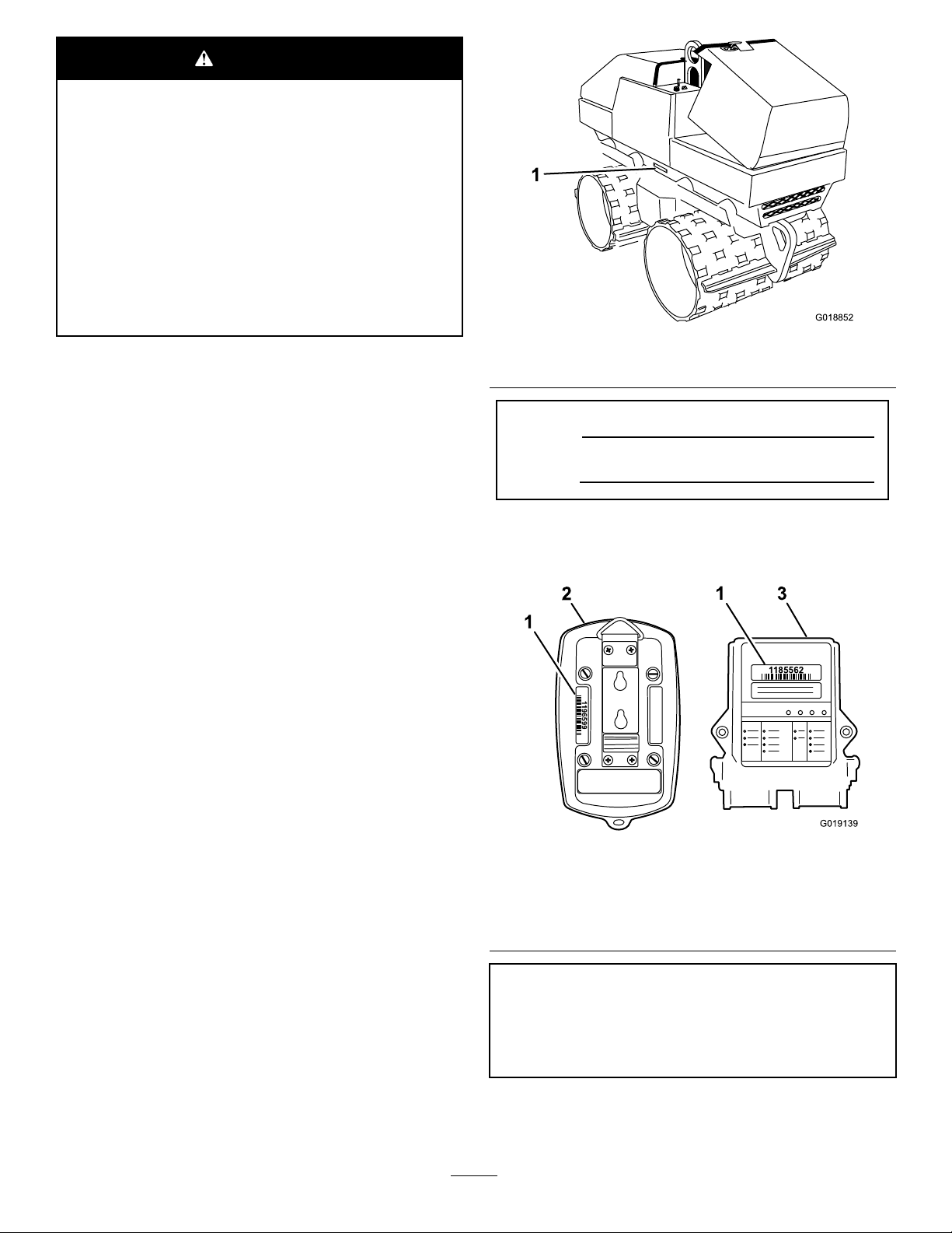
Figure1identiesthelocationofthe
1.Modelandserialnumberlocation
ModelNo.
SerialNo.
Figure2showsthelocationoftheidenticationnumberson
radio-controltransmitterandradio-controlreceiver.Writethe
numbersinthespaceprovided.
Figure2
1.Transmitterserialnumber
tag
2.Radio-controltransmitter4.Receiverserialnumber
3.Radio-controlreceiver
tag
TransmitterSerialNo._____________________________
ReceiverSerialNo._______________________________
©2013—TheToro®Company
8111LyndaleAvenueSouth
Bloomington,MN55420
Contactusatwww.T oro.com.
2
PrintedintheUSA
AllRightsReserved
Page 3

Thismanualidentiespotentialhazardsandhassafety
messagesidentiedbythesafetyalertsymbol(Figure3),
whichsignalsahazardthatmaycauseseriousinjuryordeath
ifyoudonotfollowtherecommendedprecautions.
Figure3
1.Safetyalertsymbol
Thismanualuses2otherwordstohighlightinformation.
Importantcallsattentiontospecialmechanicalinformation
andNoteemphasizesgeneralinformationworthyofspecial
attention.
3
Page 4

Contents
Introduction..................................................................2
Safety...........................................................................5
SafeOperatingPractices...........................................5
StabilityData..........................................................7
SlopeChart............................................................8
TiltChart...............................................................9
SafetyandInstructionalDecals................................10
ProductOverview.........................................................13
Controls...............................................................14
Specications........................................................21
Operation....................................................................21
Pre-startChecklist..................................................22
Fuel......................................................................22
AccessingtheMachine............................................24
EngineOilandHydraulicFluid................................25
StartingandStoppingtheEngine..............................27
StoppingtheMachine.............................................28
UsingtheParkingBrake..........................................28
MovingaNon-functioningMachine.........................30
LiftingtheMachine................................................30
PreparingtheMachineforTransport.........................31
MovingandVibratingOperation..............................32
RecoveringtheMachineAfteraTip-over
Event................................................................35
Maintenance.................................................................39
RecommendedMaintenanceSchedule(s)......................39
PremaintenanceProcedures........................................40
Lubrication...............................................................40
GreasingtheMachine.............................................40
EngineMaintenance..................................................41
ChangingtheEngineOilandFilter...........................41
ServicingtheAirFilter............................................44
EngineHardware...................................................45
FuelSystemMaintenance...........................................46
ReplacingtheFuelFilter/WaterSeparator
Canister.............................................................46
DrainingtheFuelTank...........................................47
FuelLinesandFuelInjectors...................................48
ElectricalSystemMaintenance....................................49
ServicingtheBattery...............................................49
ElectricalandElectronic..........................................51
CoolingSystemMaintenance......................................53
ServicingtheCoolingSystem...................................53
HydraulicSystemMaintenance....................................54
ReplacingtheHydraulicFilter..................................54
ChangingtheHydraulicFluid...................................55
CheckingtheHydraulicLines...................................56
HydraulicandFuelTankAccess...................................57
RemovingtheRight-sidePanel.................................57
InstallingtheRight-sidePanel..................................57
EccentricMaintenance...............................................58
ChangingtheEccentricLubricant.............................58
Cleaning...................................................................59
RemovingDebrisfromtheMachine..........................59
CleaningtheChassis...............................................59
Storage........................................................................60
RemovingtheMachinefromStorage.........................60
Troubleshooting...........................................................61
4
Page 5

Safety
Improperuseormaintenancebytheoperatororowner
canresultininjury.Toreducethepotentialforinjury,
complywiththesesafetyinstructionsandalways
payattentiontothesafetyalertsymbol,which
means:
instruction.Failuretocomplywiththeinstructionmay
resultinpersonalinjuryordeath.
SafeOperatingPractices
Caution
,
W ar ning
,or
Danger
—personalsafety
–Neveraddfueltothemachineordrainfuelfromthe
machineindoors.
–Allowtheenginetocoolbeforefuelingthemachine.
–Donotsmokewhilefuelingthemachine.
•Checkthattheoperator'spresencecontrols,safety
switches,andshieldsareattachedandfunctioning
properly.Donotoperateunlesstheyarefunctioning
properly.
•Beforecompactingsoil,havetheareamarkedfor
undergroundutilities.
Thisproductiscapableofcrushingoramputatinghandsand
feet.Alwaysfollowallsafetyinstructionstoavoidserious
injuryordeath.
WARNING
Engineexhaustcontainscarbonmonoxide,an
odorless,deadlypoisonthatcankillyou.
Donotruntheengineindoorsorinanenclosed
area.
Training
•ReadtheOperator'sManualandothertrainingmaterial.If
theoperator(s)ormechanic(s)cannotreadEnglish,itis
theowner'sresponsibilitytoexplainthismaterialtothem.
•Becomefamiliarwiththesafeoperationoftheequipment,
operatorcontrols,andsafetysigns.
•Alloperatorsandmechanicsshouldbetrained.The
ownerisresponsiblefortrainingtheusers.
•Neverletchildrenoruntrainedpeopleoperateorservice
theequipment.Localregulationsmayrestricttheageof
theoperator.
•Theowner/usercanpreventandisresponsiblefor
accidentsorinjuriesoccurringtohimselforherself,other
peopleorproperty.
Preparation
•Evaluatetheterraintodeterminetheproperandsafe
actionstoperformthejob.Onlyuseaccessoriesand
attachmentsapprovedbythemanufacturer.
•Wearappropriateclothingincludinghardhat,safety
glasses,longpants,safetyshoes,andhearingprotection.
Longhair,looseclothingorjewelrymaygettangledin
movingparts.
•Inspecttheareawheretheequipmentistobeusedand
removeallobjectssuchastools,buildingmaterials,and
personalitemswhichcanbedamagedbythemachine.
•Useextracarewhenhandlingfuels.Theyareammable
andvaporsareexplosive.
–Useonlyanapprovedcontainerforstoringand
transportingfuel.
–Neverremovethefuelcaporaddfueltothemachine
withtheenginerunning.
Operation
•Neverrunanengineinanenclosedarea.
•Nevercarrypeople,animals,orequipmentontopofthe
machine.
•Onlyoperateingoodlight,keepingawayfromholesand
hiddenhazards.
•Besurealltractioncontrolsareinneutralandparking
brakeisengagedbeforestartingtheengine.
•Slowdownanduseextracareonhillsides.Soilconditions
affectthemachine'sstability.
•Neverparkonahill.
•Neveroperatethemachinewiththevibrationfunction
On,andmovingacrossthesideofahill.
•Donotoperateinstandingwater.
•Donotparkthemachineforanextendedperiodina
trench,ditch,orlow-lyingareathatmightllwithwater.
Liftormovethemachinetoalevel,welldrainedsurface.
•Donotoperateattheedgeofembankmentsorroads
becausethemachinemaytipover.
•Slowdownandusecautionwhenmakingturnsand
crossingroadsandsidewalks.
•Usecarewhenapproachingblindcorners,shrubs,trees,
orotherobjectsthatmayobscurevision.
•Stoponlevelground,engageparkingbrake,shutoffthe
enginebeforeleavingtheoperator'spositionforany
reason.
•Lookbehindanddownbeforebackinguptobesureof
aclearpath.
•Ensurethattheareaisclearofotherpeoplebefore
operatingthemachine.Stopthemachineifanyoneenters
thearea.
•Nevercarrypassengersandkeeppetsandbystanders
away.
•Keepfeetclearofdrums.
•Hearingprotectionisrequiredwhenoperatingthis
equipment.
•Donotoperatethemachineundertheinuenceof
alcoholordrugs.
•Locatethepinchpointareasmarkedonthemachineand
keephandsandfeetawayfromtheseareas.
5
Page 6

•Forfootprotection,wearsteeltoeshoesortoepads.
•Neveroperatewiththeguardsnotsecurelyinplace.Be
sureallinterlocksareattached,adjustedproperly,and
functioningproperty.
•Donotexceedtheratedoperatingcapacityofthe
machine,asthemachinemaybecomeunstablewhichmay
resultinlossofcontrol.
•Donotchangetheenginegovernorsettingoroverspeed
theengine.
•Usecarewhenloadingorunloadingthemachineintoa
trailerortruck.
•Neverleavethemachinerunningunattended.Always
stoptheengine,settheparkingbrake,andremovethe
keybeforeleaving.
•Neverjerkthecontrols;useasteadymotion.
•Watchfortrafcwhenoperatingnearorcrossing
roadways.
•Donottouchpartswhichmaybehotfromoperation.
Allowthemtocoolbeforeattemptingtomaintain,adjust,
orservice.
•Checkforoverheadclearances(i.e.branches,doorways,
electricalwires)beforedrivingunderanyobjectsanddo
notcontactthem.
•Ensurethatyouoperatethemachineinareaswhere
therearenoobstaclesincloseproximitytotheoperator.
Failuretomaintainadequatedistancefromtrees,walls,
andotherbarriersmayresultininjuryasthemachine
backsupduringoperationiftheoperatorisnotattentive
tothesurroundings.Onlyoperatetheunitinareaswhere
thereissufcientclearancefortheoperatortosafely
maneuvertheproduct.
•Lightningcancausesevereinjuryordeath.Iflightning
isseenorthunderisheardinthearea,donotoperate
themachine;seekshelter.
SlopeOperation
Slopesareamajorfactorrelatedtoloss-of-controland
tip-overaccidents,whichcanresultinsevereinjuryordeath.
Allslopesrequireextracaution.
•Donotparkthemachineonahillsideorslope.
•Ifpossible,avoiddrivingthemachineacrossaslope.
Whencrossingaslopeisnecessary,drivethemachine
straightuptheslope,acrossthetop,andthenstraight
downtheslope.
•Slowdownandusecautionwhenmakingturnsandwhen
changingdirectionsonslopes.
•Donotoperatethemachineonhillsidesorslopes
exceedingtheanglesrecommendedinStabilityData
(page7).SeealsotheSlopeChart(page8)andTiltChart
(page9).
•Neveroperatethemachinewiththevibrationfunction
On,andmovingupordownagradethatisgreaterthan
45percent(24°).
•Neveroperatethemachinewiththevibrationfunction
Off,andmovingupordownagradethatisgreaterthan
55percent(29°).
•Neveroperatethemachinewiththevibrationfunction
Off,andmovingacrossthesideofahillwithagradethat
isgreaterthan18percent(10°).
•Removeobstaclessuchasrocks,treelimbs,etc.fromthe
workarea.Watchforholes,ruts,orbumps,asuneven
terraincouldoverturnthemachine.Tallgrasscanhide
obstacles.
•UseonlyToro-approvedattachments.Attachmentscan
changethestabilityandtheoperatingcharacteristics
ofthemachine.Warrantymaybevoidedifusedwith
unapprovedattachments.
•Keepallmovementsonslopesslowandgradual.Donot
makesuddenchangesinspeedordirection.
•Avoidstartingorstoppingonaslope.Ifthemachine
losestraction,ensurethatthevibrationfunctionisturned
totheOffpositionandproceedslowly ,straightdown
theslope.
•Avoidturningonslopes.Ifyoumustturn,turnslowly .
•Donotoperateneardrop-offs,ditches,orembankments.
Themachinecouldsuddenlyturnoverifadrumgoes
overtheedgeofaclifforditch,orifanedgecavesin.
•Donotoperateonwetgrass.Reducedtractioncould
causesliding.
MaintenanceandStorage
•Parkthemachineonalevelsurface,settheparking
brake,stoptheengine,andremovethekey .W aitforall
movementtostopbeforeadjusting,cleaning,orrepairing.
•Cleandebrisfromthedrives,mufer,andengineto
helppreventres.Cleanupfuel,oil,andhydraulicuid
spillage.
•Lettheenginecoolbeforestoringanddonotstorenear
ame.
•Donotstorefuelnearamesordrainindoors.
•Neverallowuntrainedpersonneltoservicethemachine.
•Usejackstandstosupportcomponentsofthemachine
whenrequired.
•Carefullyreleasepressurefromcomponentswithstored
energy.
•Disconnectthebatterybeforemakinganyrepairs.
Disconnectthenegativeterminalrstandthepositive
last.Reconnectpositiverstandnegativelast.
•Keephandsandfeetawayfrommovingparts.Ifpossible,
donotmakeadjustmentswiththeenginerunning.
•Chargebatteriesinanopenwellventilatedarea,away
fromsparkandames.Unplugthechargerbefore
connectingordisconnectingitfromthebattery.Wear
protectiveclothinganduseinsulatedtools.
6
Page 7
•Keepallpartsingoodworkingconditionandallhardware
tightened.Replaceallwornordamageddecals.
•Keepnutsandboltstight.Keepequipmentingood
condition.
•Nevertamperwithsafetydevices.
•Keepthemachinefreefromthebuildupofmud,rocks,
orotherdebris.Cleanupoilorfuelspillage.Allowthe
machinetocoolbeforestoring.
•Useextracarewhenhandlingfuels.Theyareammable
andvaporsareexplosive.
–Useonlyanapprovedcontainer.
•Batteryacidispoisonousandcancauseburns.Avoid
contactwithskin,eyes,andclothing.Protectyourface,
eyes,andclothingwhenworkingwithabattery.
•Batterygasescanexplode.Keepcigarettes,sparksand
amesawayfromthebattery.
•Keepyourbodyandhandsawayfrompinholeleaks
ornozzlesthatejecthighpressurehydraulicuid.Use
cardboardorpapertondhydraulicleaks;neveruse
yourhands.Hydraulicuidescapingunderpressurecan
penetrateskinandcauseinjuryrequiringsurgerywithina
fewhoursbyaqualiedsurgeonorgangrenemayresult.
–Neverremovethefuelcaporaddfuelwhenthe
engineisrunning.Allowtheenginetocoolbefore
refueling.Donotsmoke.
–Neverrefuelthemachineindoors.
–Neverstorethemachineorfuelcontainerinside
wherethereisanopename,suchasnearawater
heaterorfurnace.
–Neverllafuelcontainerwhileitisinsideavehicle,
trunk,cargoboxofatruck,oranysurfaceotherthan
theground.
–Keepcontainernozzleincontactwiththetankduring
lling.
•Stopandinspecttheequipmentifyoustrikeanobject.
Makeanynecessaryrepairsbeforerestarting.
•UseonlygenuineTororeplacementpartstoensurethat
originalstandardsaremaintained.
StabilityData
Thefollowingtableslistthemaximumsloperecommended
forthemachineinthepositionslistedinthetables.Slopes
overthelisteddegreeinthestabilitydatatablemaycausethe
machinetobecomeunstable.
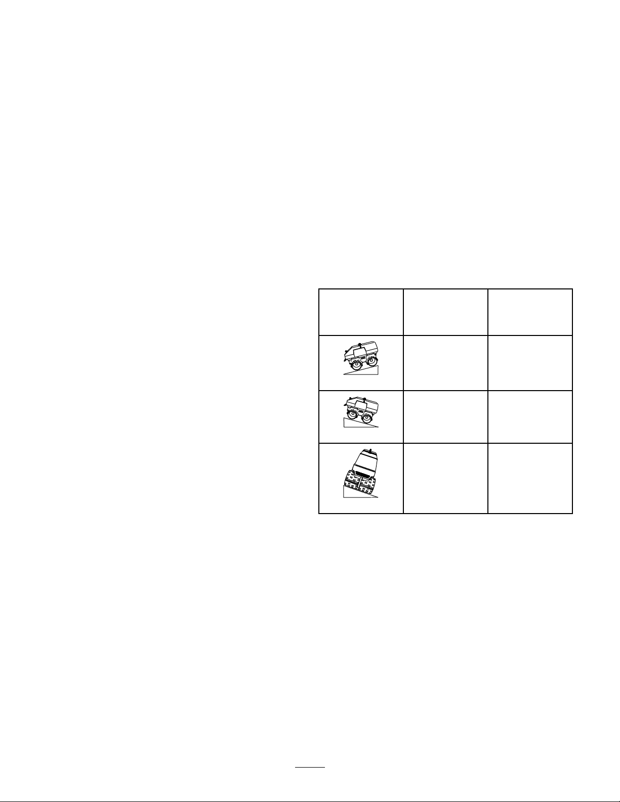
StabilityDataTable
SlopeOperation
Type:
Uphill
Downhill
Operational
Limit:
VibrationOff
Grade(Degrees)
55%(29°)45%(24°)
55%(29°)45%(24°)
18%(10°)0%(0°)
Operational
Limit:
VibrationOn
Grade(Degrees)
7
Acrossthehill
Page 8
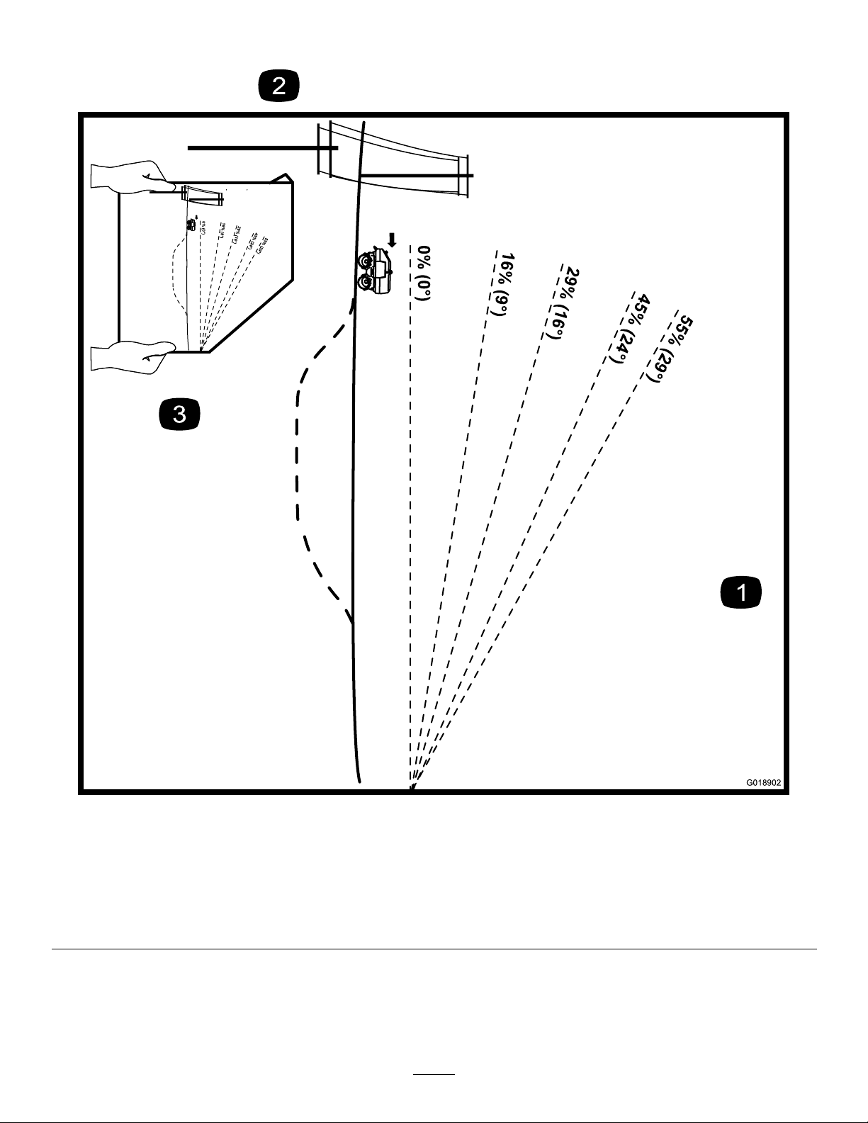
SlopeChart
0% (0°)
0% (0°)
G018902
Figure4
Thispagemaybecopiedforpersonaluse.
1.Todeterminethemaximumslopeyoucansafelyoperatethemachine,refertotheStabilityDatasection.Usethegradeindicator
todeterminethegradeofinclinebeforeoperating.Donotoperatethismachineonagradegreaterthanthatspeciedinthe
StabilityDatasection.Foldalongtheappropriatelinetomatchtheobservedgrade.
2.Alignthisedgewithaverticalsurfacesuchasautilitypole,tree,building,etc.
3.Exampleofhowtocomparegradewithfoldededge.
Note:Fortiltlimits,refertoFigure5.
8
Page 9
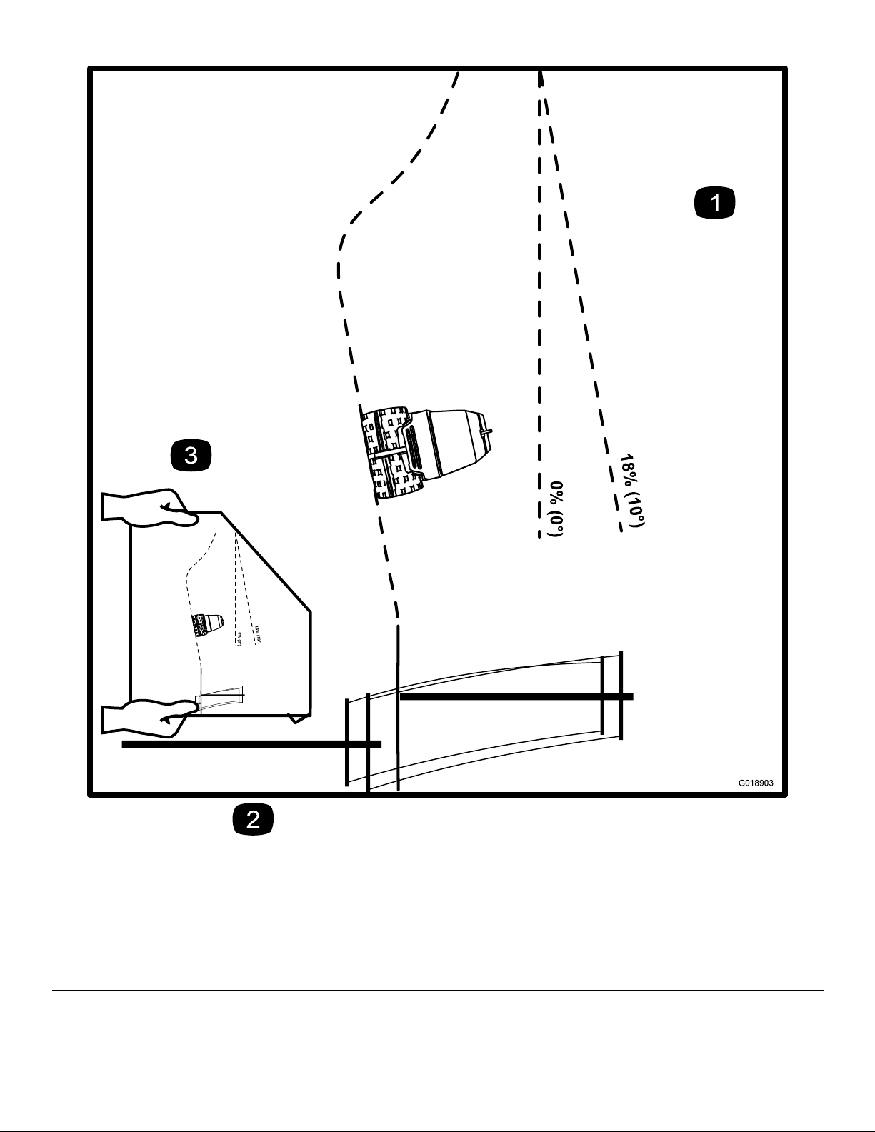
TiltChart
0% (0°)
G018903
0% (0°)
18% (10°)
Figure5
Thispagemaybecopiedforpersonaluse.
1.Todeterminethemaximumtiltyoucansafelyoperatethemachine,refertotheStabilityDatasection.Usethetiltindicatorto
determinethedegreeofslopebeforeoperating.Donotoperatethismachineonaslopegreaterthanthatspeciedinthe
StabilityDatasection.Foldalongtheappropriatelinetomatchtherecommendedslope.
2.Alignthisedgewithaverticalsurfacesuchasautilitypole,tree,building,etc.
3.Exampleofhowtocompareslopewithfoldededge.
Note:Forslopelimits,refertoFigure4.
9
Page 10

SafetyandInstructionalDecals
Safetydecalsandinstructionsareeasilyvisibletotheoperatorandarelocatednearanyareaofpotential
danger.Replaceanydecalthatisdamagedorlost.
1.Remote-controlmode9.Fast—travelspeed
2.Manualmode
3.Warning—emergencystop
4.Pulluptoruntheengine
5.Pressdowntostoptheengine13.Fast—enginespeed
6.Forwardvibration
7.Reversevibration15.Enginespeedcontrol
8.Vibrationdirectiontoggle
10.Slow—travelspeed18.Right-forwardtraction
11.VibrationOn
12.Travel-speed/vibration20.Warning—readtheOperator’sManual.
14.Slow—enginespeed
16.Left-forwardtraction
127–1660
17.Left-reversetraction
19.Right-reversetraction
21.Explosionhazard,fuel—stopthe
engineandextinguishallamesbefore
refueling.
22.Warning—wearhearingprotection;
weareyeprotection.
23.Warning—keepawayfrommoving
parts;keepguardsandshieldsin
place.
24.Warning—keepbystandersawaywhen
operatingthemachine.
10
Page 11
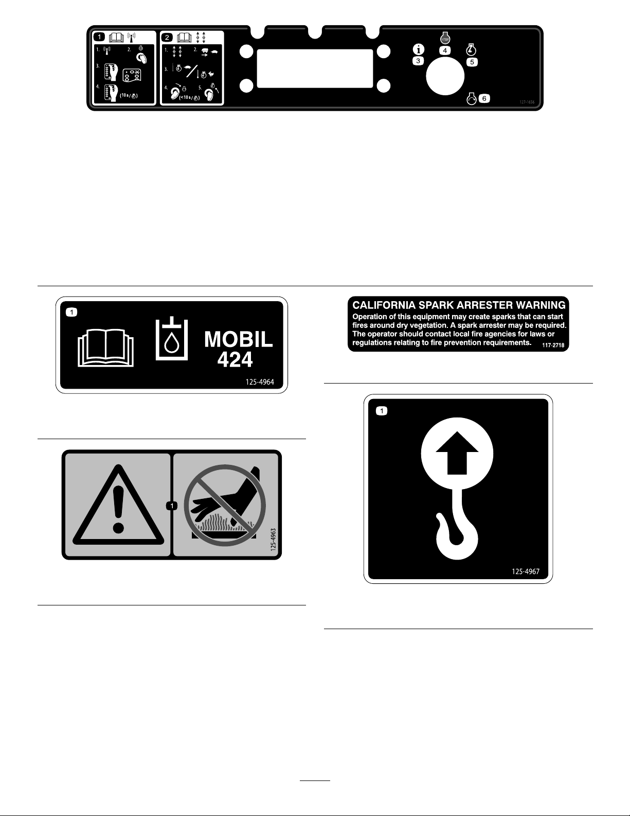
127–1656
1.ReadtheOperator’sManualforinformationonthe
radio-controlmode—1)Positiontheswitchtotheradio-control
mode;2)Rotatethekeytotheengine-stopposition;3)Press
thelink/startbuttononce—waitfortheactive-linklightto
illuminate;4)Pressthelink/startbuttontostarttheengine.
2.ReadtheOperator’sManualforinformationonthemanual
mode—1)Positiontheswitchtothemanualmode;2)Position
thetractionswitchtoslow;3)Iftheengineiswarm,position
theengine-speedswitchtoslow;iftheengineiscold,
positiontheengine-speedswitchtofast;4)Turnthekeyto
theengine-startpositionfor10secondsorlesstostartthe
engine,thenreleasethekeytotheengine-runposition.
3.LEDdisplay6.Engine—start
125–4964
1.ReadtheOperator’sManualforoilinformation.
4.Engine—stop
5.Engine—run
117–2718
125–4963
1.Warning—keephandsawayfromhotsurfaces
125–4967
1.Liftpoint
11
Page 12
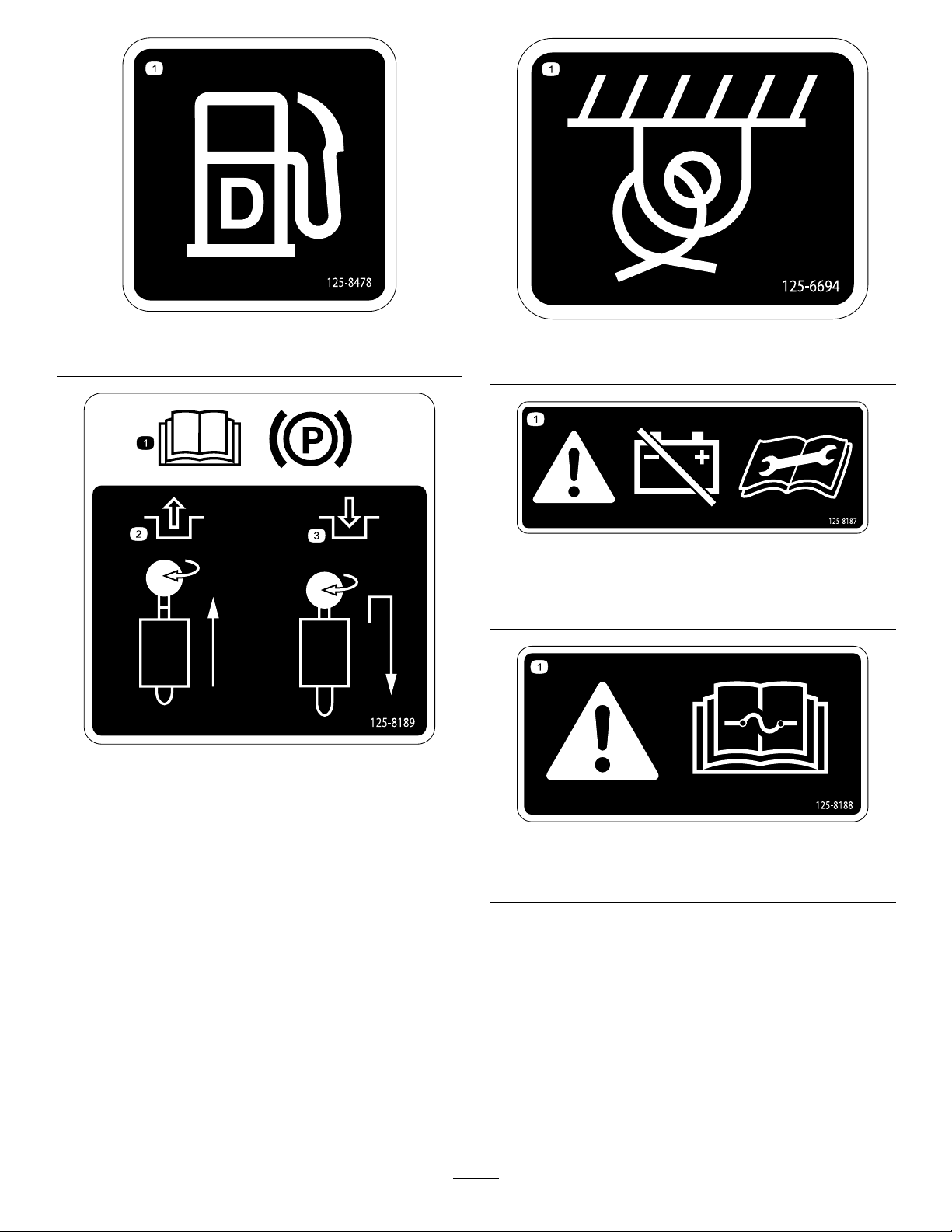
1.Dieselfuel
125–8478
1.Tiedownlocation
125–6694
125–8187
1.Warning—disconnectthebatterandconsulttheOperator’s
Manualbeforeperformingserviceormaintenanceonthe
machine.
125–8189
1.ReadtheOperator’s
Manualforinformation
onoperatingtheparking
brake.
2.Toreleasetheparking
brake,pulltheknob
upfully ,rotateit90°
clockwise,andthengently
releasetheknob.
3.Tosettheparkingbrake,
pulltheknobupslightly ,
rotateit90°clockwise,
andthengentlyrelease
theknob.
125–8188
1.Warning—readtheOperator’sManualforinformationon
fuses.
12
Page 13
ProductOverview
G018905
1
2
3
4
5
6
5
7
5
8
9
10
11
G018906
1
2
3
4
5
6
7
9
10
8
11
7
12
4
7
G018925
1
2
3
5
6
8
9
10
11
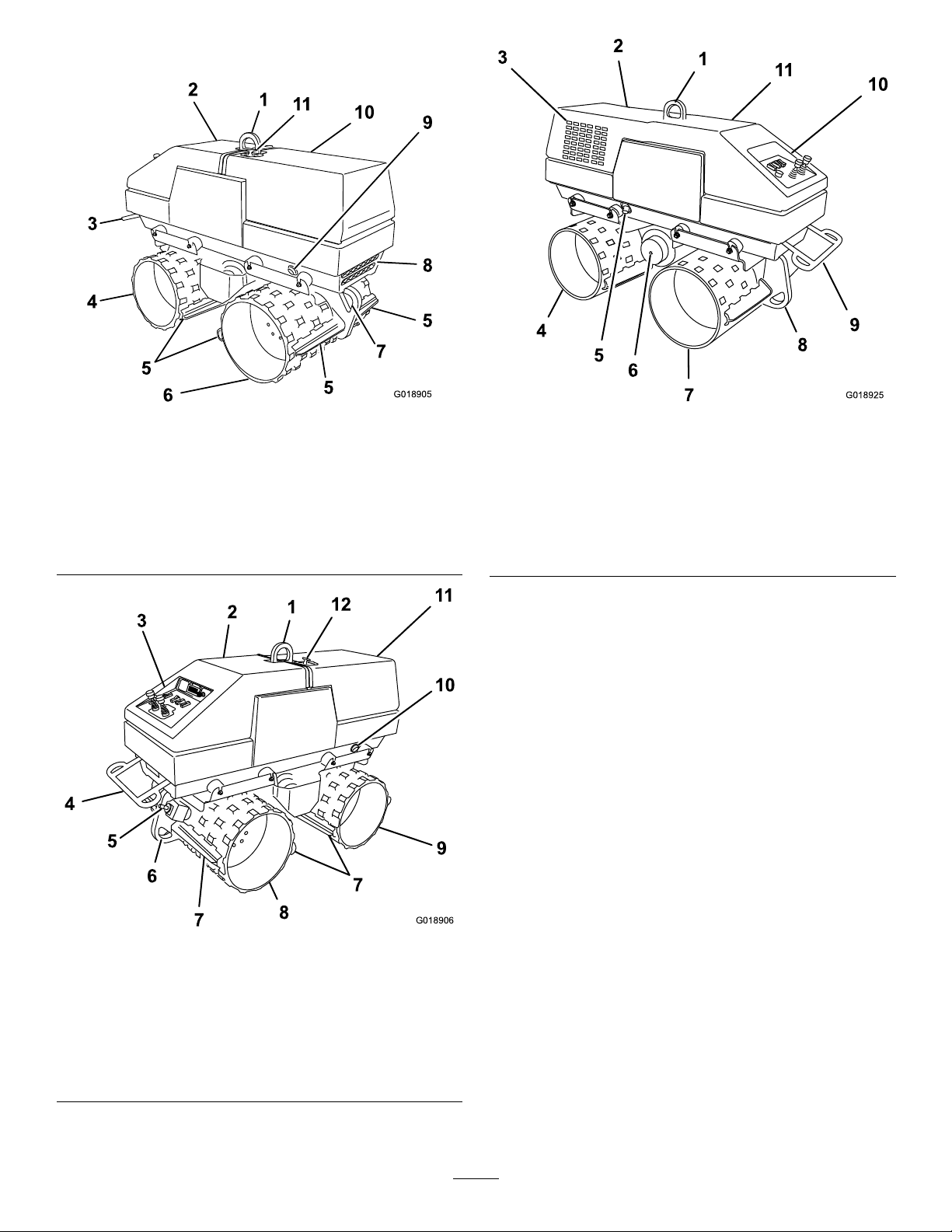
Figure6
1.Liftingring
2.Rearhood8.Airinlet
3.Safetybar9.Oil-coolerduct
4.Right-reardrum10.Fronthood
5.Scraperbar
6.Right-frontdrum
7.Forward,tie-downring
11.Hood-latchhandle
Figure8
1.Liftingring7.Left-reardrum
2.Fronthood8.Rear,tie-downring
3.Enginegrill
4.Left-frontdrum10.Controlpanel
5.Engine-exhaustpipe11.Rearhood
6.Eccentricoilplug
9.Safetybar
1.Liftingring
2.Rearhood8.Right-reardrum
3.Controlpanel9.Right-frontdrum
4.Safetybar10.Oil-coolerduct
5.Parkingbrake11.Fronthood
6.Rear,tie-downring12.Hood-latchhandle
Figure7
7.Drumscraper
13
Page 14
Controls
STOP
!
!
G018909
7
13
12
11
10
9
8
5
4
32
6
1
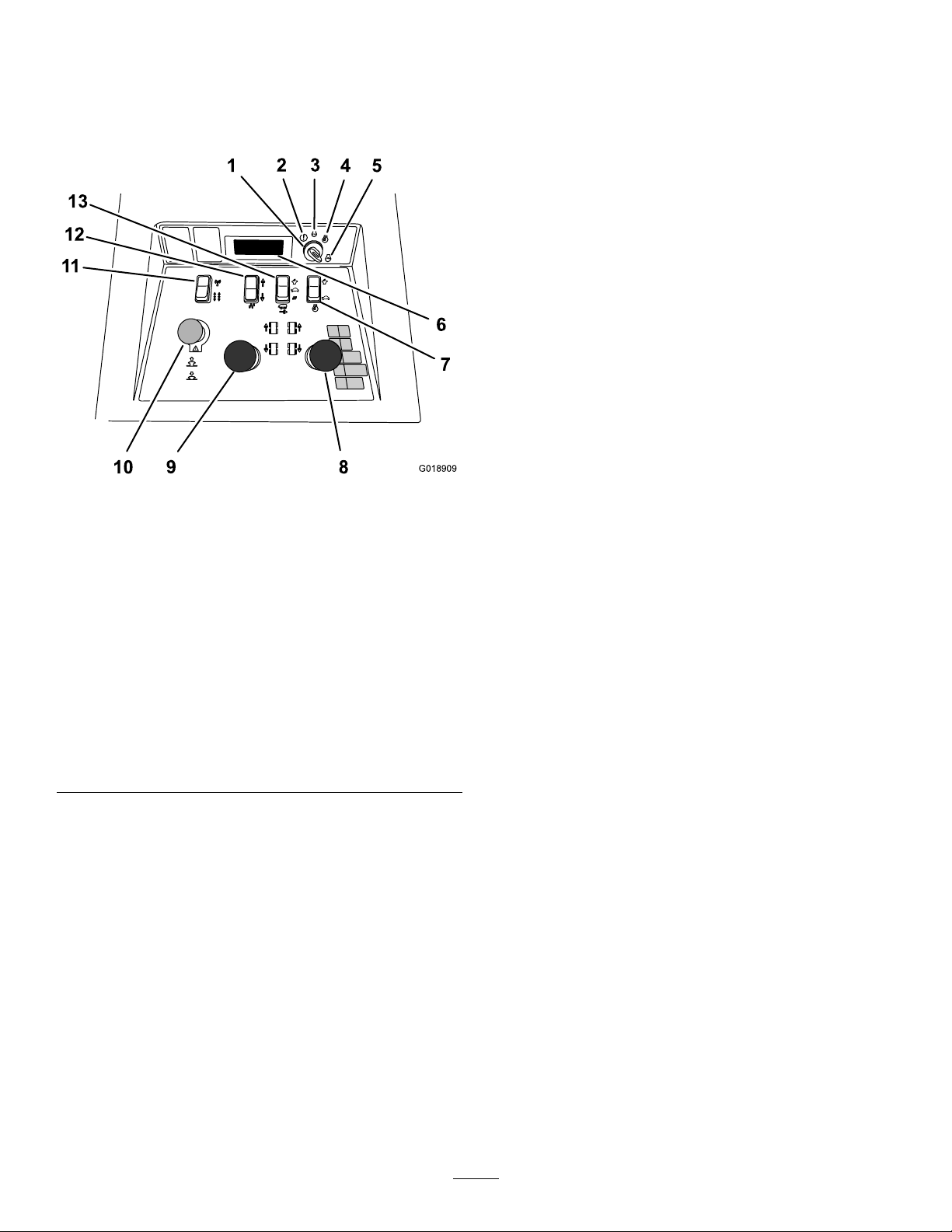
Becomefamiliarwithallthecontrols(Figure9andFigure17)
beforeyoustarttheengineandoperatethemachine.
ControlPanel
Displaywhenthekeyswitchisintheinformation
position—hourmeter—faults/warnings—software
version:Toviewoperationinformationforthemachine,
rotatethekeyswitchtotheinformationposition
(counterclockwisefromtheOffposition).
•Hourmeter
•Faultmessages
•Faulthistory
•Warnings
•Softwareversion
Note:Operationinformationisstoredinnonvolatile
memory.Intheeventthatbatterypowerislost,this
informationremainsintact.Uponrestoringbatterypower,
thestoredoperationinformationisavailablefordisplay.
HourMeter
Thehourmeterdisplayindicatesthetotalnumberofhours
themachinehasrun.
Figure9
1.Keyandkeyswitch8.Right,traction-control
2.Information9.Left,traction-control
3.Engine—stop10.Emergency-stopbutton
4.Engine—run11.Modeswitch
5.Engine—start12.Vibration-directionswitch
6.LEDdisplay
7.Engine-speedswitch(fast
|slow)
LEDDisplay
(forward/reverse)
(forward/reverse)
(remote-controlmode|
manualmode)
(forward|reverse)
13.Travel-speed/vibration
switch(fast|slow|
vibrationOn)
Locationandoperation:TheLEDdisplayislocated
onthecontrolpanel.Thedisplayisembeddedintothe
electronicignitioncontrolblock,andiscontrolledthrough
themicroprocessor.Thedisplayprovidestheoperatoror
mechanicoperatinginformationaboutthesystemsonthe
machine.Thefollowingsectiondescribestheinformation
showninthedisplay .
Displaywhilestarting-up—voltage:Duringengine
start-up,thedisplayshowsthebatteryvoltagelevel.Rotatethe
keyswitchtotheStartpositiontodisplaythebatteryvoltage.
Displaywhilerunningthemachine—rpm:Whenthe
engineisrunning,thedisplayshowstheenginerpm.After
startingthemachine,thekeyswitchwillrotatebackto
engine-runpositionandtheenginerpmisindicatedinthe
display.
RotatethekeyswitchtotheAccessorypositiontodisplay
thehourmeterinformation.
FaultMessages
Thefaultmessagesdenethesituationsthatcausetheengine
ofthemachinetoshutdownornotstart.Thesesafeguards
includeengineprotectcircuitsorothermachineprotection
devices.Faultmessageswillbeshownonthedisplayandwill
indicatewhateventhasshutdowntheengine.
Rotatethekeyswitchtotheinformationpositiontoviewthe
faultmessagesshouldtheyoccur.
•LOWOIL—thismessagedisplayswhentheproperoil
pressureisnotachievedormaintained(monitoredbythe
oilpressureswitch).
•CYLHEADTEMP—thismessagedisplayswhen
thetemperatureofthecylinderheadexceedsthesafe
operatingtemperature(monitoredbythetemperature
switchinthecylinderhead).
•TILT—thismessagedisplayswhenthemachinetipangle
isexceeded(monitoredbythetipswitch).
•ESTOP—thismessagedisplayswhentheemergency
stopbuttononthecontrolpanelisdepressed,andhas
notbeenreset(monitoredbytheemergencystopbutton
position).
Note:TheLEDdisplayalwaysindicatesthelastfault
messagethatoccurred.Thenonvolatilememoryinthe
microprocessoralwaysrequiresaninput,thereforethelast
messagewillbedisplayedevenafterthefaulthasbeen
corrected.
14
Page 15
FaultHistory
G018951
1 2
3
4
5
6
G018947
2
1
Themicroprocessorrecordsthelast20faultmessagestothe
nonvolatilememory;accessthefaulthistoryasfollows:
1.RotatethekeyswitchtotheInformationpositionto
displaythehourmeter,lastfault,andsoftwareversion
level.
2.Duringthedisplayofthelastfault,quicklyrotatethe
keyswitchtotheOffposition,andthenrotatethekey
switchtotheInformationposition.
Note:Thedisplaywillshowthelast20faults,beginningwith
themostrecent.Toturnoffthedisplayatanytime,turnthe
keyswitchtotheOffposition.
Warnings
Warningmessagesaredenedasmessagesthatindicatethe
electricalsystemisnotoperatingcorrectly.Warningmessages
willashinthedisplaywhenthemachineisrunninginthe
manualoperatormode.The3warningmessagesareas
follows:
Note:IftheVRegLortheBatLowmessageisindicatedin
thedisplay ,stoptheengine.IfaVRegLwarningmessageis
indicated,refertoyourEngineOperator'sManual.IfaBatLow
warningmessageisindicated,checkthealternatoroutput
voltageandchargeorreplacethebattery.
•VREG—thevoltageregulatorlowmessageindicatesthat
theelectricalsystemisnotchargingcorrectly.
•BATLOW—thebatterylowmessageindicatesthe
voltagelevelofthebatteryislow .Thismessagewill
displaywhenthebatteryoutputis10voltsorless.
•RPMLOW—therevolutionsperminutelowmessage
indicatestheenginespeedisbelowtheminimumspeed
(monitoredbyalternatoroutput).
SoftwareVersion
Thesoftwareversiondisplayindicatesrevisionlevelofthe
softwareforthemicroprocessor.
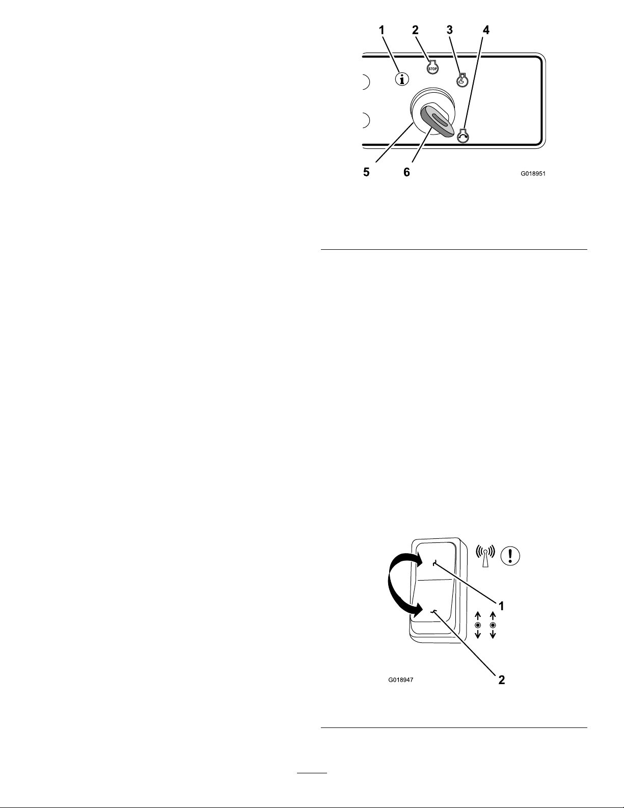
Figure10
1.Information
2.Engine—Off
3.Engine—run6.Key
4.Engine—start
5.Keyswitch
•Stoptheenginebyrotatingthekeyswitchtothe
engine-Offposition(Figure10).
•Displaythehourmeter,thelastfaultmessage,and
thesoftwareversionbyrotatingthekeyswitchtothe
Informationposition(Figure10).
ModeSwitch
Usethemodeswitchtocontrolthereceptionofcommands
fromtheremote-controltransmitter.Selectingtheswitchto
theradio-controlmodeormanual-modepositionchanges
intendedmachineformofoperation(Figure11).
Important:Prolongthebatterylifeofthemachineby
selectingthemodeswitchtothe
whenthemachineisnotinuse.
Note:Selectthemodeswitchtotheradio-controlmode
positiontooperatethemachinewiththeremote-control
transmitter.
Selectthemodeswitchtothemanual-modepositionto
operatethemachinewiththecontrolpanel.
man ual mode
position
Todisplaythesoftwareversioninformation,rotatethekey
switchtotheInformationposition.
KeySwitch
Usethekeyswitchtostartandruntheengine,stopthe
engine,andpowertheaccessorydisplay.Thekeyswitchhas4
positions:Information,Off,Run,andStart.
•Starttheenginebyrotatingthekeyswitchtothe
engine-startposition,andthenreleasingthekeywhen
enginestarts;thekeyitwillmoveautomaticallytothe
engine-runposition(
Figure10).
Figure11
1.Radio-controlmode2.Manualmode
15
Page 16

VibrationDirectionSwitch
2
1
G018948
3
1
2
G018949
2
1
G018950
G021430
G018946
1
2
Usethevibrationdirectionswitchtoselectthedirection
eccentricrotationwhenthevibrationfunctionactive(Figure
12).
Figure12
1.Vibrateforward
2.Vibratereverse
Important:Performmachineoperationssuchas
movingthemachineandvibrationfunctionswiththe
engine-speedswitchinthefast,engine-speedposition.
Figure14
1.Fast,engine-speed
2.Slow,engine-speed
•Vibrationmovementinaforwarddirection.
•Vibrationmovementinthereversedirection.
Travel-speed/VibrationSwitch
Important:Selecttheslow,travel-speedsettingwhen
movingthemachineinandoutofthetrench,when
loadingthemachineontoatransportvehicle,andwhen
unloadingthemachinefromatransportvehicle.
Usethetravel-speedswitchtocontroltravelspeedofthe
machine(vibrationOff)oractivatethemachine-vibration
function(Figure13).
Note:Thevibrationfunctionisinoperativewhenmoving
themachineinthefast-travelspeedortheslow-travelspeed
settings.
EmergencyStopButton
Usetheemergencystopinanysituationwhentheimmediate
stopofthemachineisrequired.Pressingtheemergencystop
buttonwillshutthemachineoffimmediately.
Theemergencystopbuttonislocatedonthecontrolpanel
andislabeled
belowthered-coloredbutton.
Performthefollowingstepstostopthemachineinan
emergencysituation,andresetthemachinewhenthe
emergency-stopconditioniscorrected:
1.Presstheemergencystopbuttondowntoimmediately
shutoffthemachine(Figure15).
Figure13
1.Fast-travel(vibration-off)3.VibrationOn(slowtravel)
2.Slow-travel(vibration-off)
Engine-speedSwitch
Usetheengine-speedswitchtochangetheengineRPM
betweentheslowandfast,engine-speedsettings(
Figure14).
Figure15
1.Emergencystopposition
2.Resetfornormaloperation
2.Pulltheemergencystopbuttonuptoresumenormal
machineoperation(
16
Figure15).
Page 17

TractionControls
G019077
1 2
ENG INE S PEE D
TRAVE L SPEE D
R
L
VIBE ON
REV
FWD
TRAVE L
G018910
1
2
3
4
5
6
7
8
9
10
11
12
13
14
Remote-controlTransmitter
Movetheleftandright,traction-controlleverstomanually
movethemachineintheforwardorreversedirection
Important:Keeptheremote-controltransmitterdry.
Donotpressurewashtheremote-controltransmitter.
(straight,leftorright)(Figure16).
Figure16
RadioSet
Aradiosetisamatchedaddresscodeandradiofrequency
foraradio-controltransmitterandtheradio-controlreceiver.
Theaddresscodesandradiofrequencyfortheradiosetare
unique,andmustmatchforthemachinetofunctionproperly.
Thisrelationshipassuresthatthetransmittercancontrolonly
onereceiver/machine,andthatmultiplecompactorscanbe
usedonthejobsitewithoutinterference.Refertothe7digit
serialnumbersthatyourecordedonpagetitledIntroduction
(Figure2).
1.Link/startbutton(green)8.Emergency-stop/power-Off
2.Lowbatterylight
(remote-control
transmitter)
3.Left,forward-traction
button(uparrow)
4.Left,reverse-traction
button(downarrow)
5.Slow,travel-speedbutton
(vibrationOff)
6.Reversevibrationbutton
(vibrationOn)
7.Slow,engine-speedbutton
(notfunctional)
Figure17
button
9.Fast,engine-speedbutton
(notfunctional)
10.Forwardvibrationbutton
(vibrationOn)
11.Fast,travel-speedbutton
(vibrationOff)
12.Right,reverse-traction
button(downarrow)
13.Right,forward-traction
button(uparrow)
14.Activelinklight(ashes)
Link/StartButton
Pressthelink/startbutton(greenbutton)toestablisharadio
linkbetweentheremote-controltransmitterandtheradio
receiverinthemachineandtostarttheengineinthemachine
(
Figure17).
Note:Thelink/startbuttonisthetopbutton(centeredleft
andright)ontheremote-controltransmitter.
Functions:
1.Establishalinktotheradioreceiverofthemachine.
2.Starttheengineofthemachine.
17
Page 18
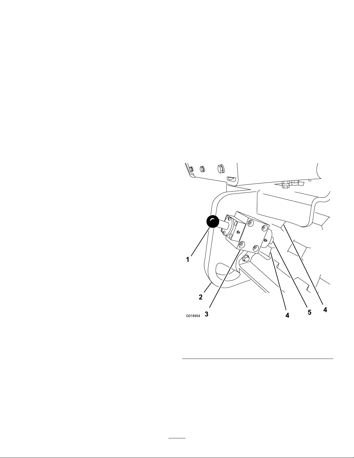
Traction-controlButtons
G018954
1
2
4
5
4
3
Emergency-stop/Power-OffButton
Pressandholdthetraction-controlbuttonstomovethe
machineintheforwardorreversedirection(straight,leftor
right)(Figure17).
Important:T ostopthemovementofthemachine,
releasethetraction-controlbuttons.
•Movethemachineforward.
•Movethemachinebackward.
•Turnthemachineleft.
•Turnthemachineright.
TravelSpeedButtons
Important:Usetheslow-travelspeedsettingwhen
movingthemachineinandoutoftrenches,when
loadingthemachineontoatrailer,andwhenunloading
themachinefromatrailer.
Usethetravelspeedbuttonsontheremote-control
transmittertocontrolthetravelspeedofthemachine
(vibrationOff)oractivatethevibrationfunctionofthe
machine(Figure17).
Note:Thevibrationfunctionisinoperativewhenmovingthe
machineinthefasttravel-speedsettingorslowtravel-speed
setting.
Presstheemergency-stop/power-Offbutton(redbutton)
turnoffthemachineinanemergencysituationorduring
normaloperation(Figure17).
Note:Theemergancy-stop/power-Offbuttonisthebottom
button(centeredleftandright)ontheremote-control
transmitter.
•Turnoffthemachineoffimmediatelyinanemergency
situation.
•Turnoffthemachineduringnormaloperation.
ParkingBrake
Theparkingbrakemechanismisaspringloadedplunger
thatrestsagainstthesurfaceofthedrumwhenthebrakeis
engaged.Usethebrakeknobtoengageanddisengagethe
parkingbrakeofthemachine;refertoUsingtheParking
Brake(page28).
•Movethemachineatminimum-travelspeed.
•Movethemachineatmaximum-travelspeed.
•Stopthevibrationfunction(pressandreleaseeitherthe
sloworfast,travel-speedbutton).
VibrationOnButtons
UsethevibeOnbuttonstoselectthedirectioneccentric
rotationwhenthevibrationfunctionactive(Figure17).
Note:Tostopthevibrationfunctionwiththeremote-control
transmitter,presstheslow,travel-speedbutton;refertoTravel
SpeedButtons(page18).
•Vibrateinaforwarddirection.
•Vibrateinareversedirection.
EngineSpeedButtons
Theengine-speedbuttonsontheremote-controltransmitter
donotfunction.Theenginespeedisautomaticallycontrolled
bythemicroprocessorinthemachinewhenoperatinginthe
remote-controlmode.
Figure18
1.Brakeknob4.Drumpad
2.Rear,tie-downring5.Plunger
3.Parkingbrake
Whenthemachineisstartedwiththeremote-control
transmitter,theenginewillstartattheslow-enginespeed,
after1secondtheenginewillautomaticallyacceleratetothe
fast-enginespeedandsustainthatspeed.
18
Page 19
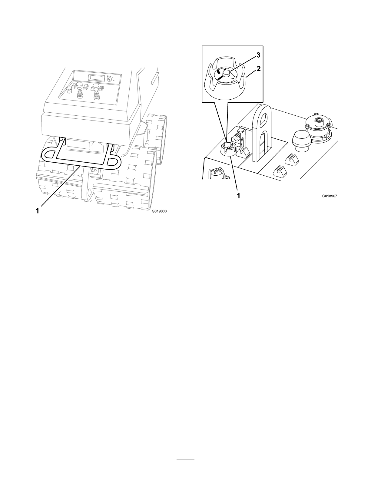
Anti-crushBar
G019000
1
G018967
2
1
3
FuelGauge
Theanti-crushbarisasafetydevicethatislocatedattherear
ofthemachine,andbelowthecontrolpanel.Whentriggered,
theanti-crushbarpreventsthemachinefromreversetravel
intheeventthattheoperatorbecomesentrappedbehindthe
machine.
Thefuelgaugeispartofthefuel-tankcap,andindicatesthe
leveloffuelinthefueltank.
Figure20
1.Anti-crushbar
Figure19
1.Fuel-tankcapandfuel
gauge
2.Fuel-tankcap
3.Fuelgauge
19
Page 20
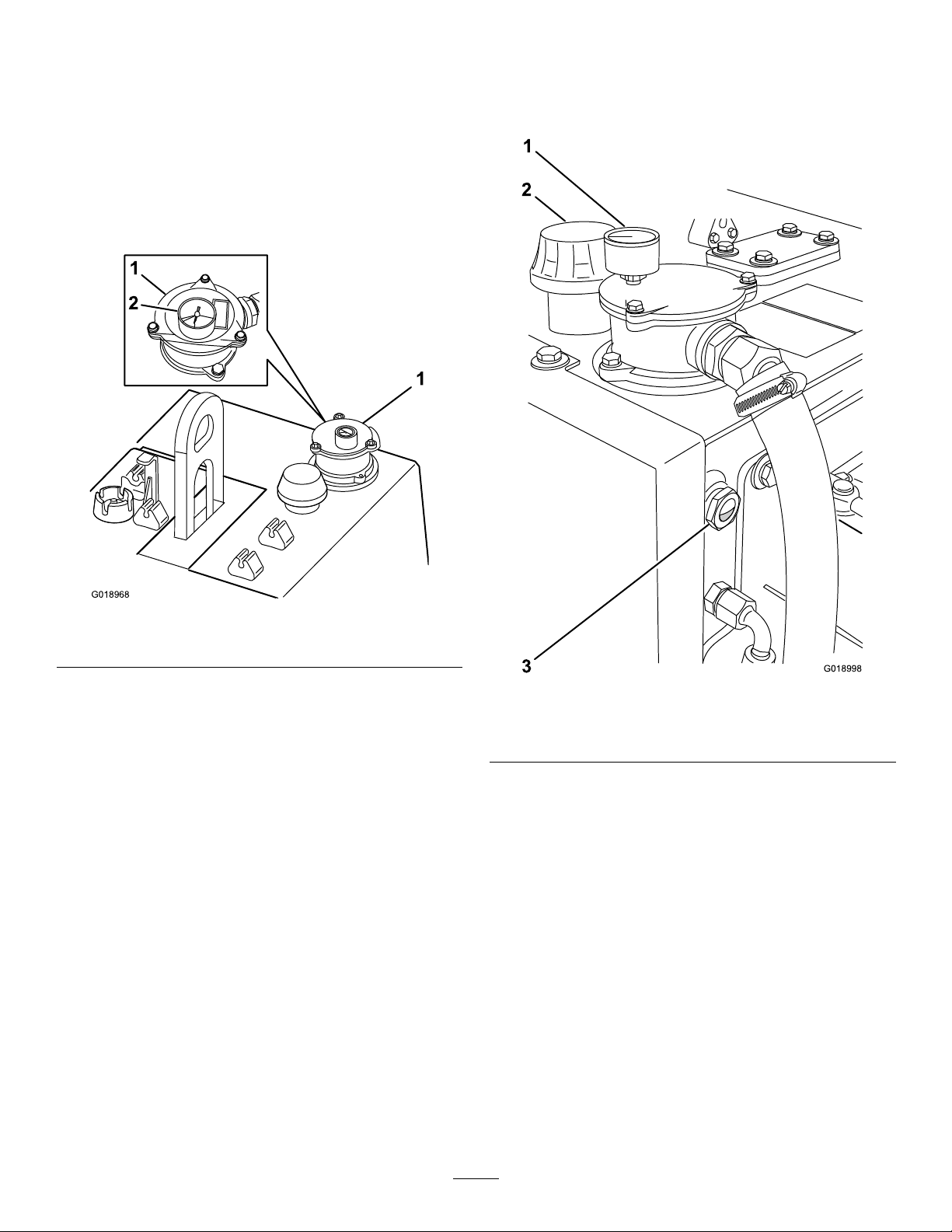
Hydraulic-lterGauge
G018968
1
1
2
G018998
1
2
3
Hydraulic-tankGauge
Thehydraulic-ltergaugeindicatesthepressureofhydraulic
uidowingthroughthehydrauliclter.
Thepressurerangesforthehydraulic-ltergaugeareas
follows:
•Normal(green):0to137kPa(0to20PSI)
•Caution(yellow):137to172kPa(20to25PSI)
•Servicethelter(red):172to689kPa(25to100PSI)
Usethehydraulic-tankgaugetoobservethelevelofhydraulic
uidinthetank.Thetankgaugeislocatedontheleft-rear
sideofthehydraulictank.
Figure21
1.Hydraulic-lterhousing2.Hydraulic-ltergauge
Figure22
1.Hydraulic-ltergauge
2.Cap/breather
3.Hydraulic-tankgauge
20
Page 21

Specications
Note:Specicationsanddesignaresubjecttochange
withoutnotice.
Model68039
Width
Length
Height
Weight
Engineoilcapacity
Fuelcapacity
Hydraulictankcapacity
VibrationSpecications
DescriptionValue
VibrationFrequency
CentrifugalForce69.87kN(15709lb)
TotalAppliedForce
StaticLinearPressure85N/cm(48psi)
DynamicLinearPressure
TotalAppliedLinearPressure
StaticAppliedPadfoot
Pressure
DynamicAppliedPadfoot
Pressure
TotalAppliedPadfootPressure647.5N/cm(443.3psi)
33.3Hz(2000vpm)
82.7kN(18609lb)
432N/cm(247psi)
516N/cm(295psi)
516N/cm(73.06psi)
127N/cm(370psi)
86cm(34inch)
167.7cm(66inch)
119cm(46.4inch)
1406Kg(3100lb)
0.95L(2qt)
11.3L(3USgallon)
49L(13USgallon)
Operation
WARNING
•Nevermovethemachineacrossaslopegreater
than18%grade(10°).
•Neverparkthemachineonahill.
CAUTION
•Beforestartingthemachine,makesurethat
therearenopersonsnearthemachineor
obstaclesunderthemachine.
•Exposuretoloudnoisecancausehearing
impairmentorloss.Wearearprotectionwhen
operatingthemachine.
•Themachinecaninjureyourfeet.Keepfeet
clearofdrumsandwearfootprotection,steeltoe
shoes,ortoepadswhenoperatingthemachine.
Important:Usersmustbetrainedtooperatethe
machine.Readthe
Owner’ s Man ual.
Important:Beforeoperatingthemachine,checkthe
fuelandoillevel,andremovedebrisfromthemachine.
Ensurethattheareaisclearofpeopleanddebris.Y ou
shouldalsoknowandhavemarkedthelocationsofall
utilitylines.
Operator’ s Man ual
and
Engine
Learntooperatethemachinesafely.
Note:Determinetheleftandrightsidesofthemachine
fromthenormaloperatingposition.
21
Page 22

Pre-startChecklist
FillingtheFuelTank
1.Checktheengineoillevel.
2.Checktheengineairlterelement.
3.Checktheenginefuellevel.
Note:Alwaysuseclean,freshfueltopreventdamage
tothefuelinjectioncomponents.
4.Checkthehydraulicuidlevel.
5.Checkthehardwareforlooseness.
6.Checkthehosesforloosettingsandsignsofaleak.
7.CheckthattheEmergencyStopbuttonisnotdamaged,
andthatthebottommovesupanddown.
8.CheckthattheAnti-crushbar,switch,andactuation
componentsarenotdamaged,andthatallpartsmove
andworkproperly .
Fuel
Useonlyclean,freshdieselfuelwithanultralow(<15ppm)
sulfurcontent.Theminimumcetaneratingforthedieselfuel
shouldbe40.Purchasefuelinquantitiesthatcanbeused
within30daystoensurefuelfreshness.
Fueltankcapacity:11.5L(3USgallon)
Important:Donotusekeroseneorgasolineinsteadof
dieselfuel.Failuretoobservethiscautionwilldamage
theengine.
•Outsideairtemperaturesabove20°F(-7°C),use
summergradedieselfuel(No.2-D)
Note:Useofsummergradefuelabove20°F(-7°C)will
contributetowardlongerfuelpumplifeandincreased
power.
•Outsideairtemperaturesbelow20°F(-7°C),usewinter
grade(No.1-DorNo.1-D/2-Dblend)
Note:Useofwintergradefuelatlowertemperatures
provideseasierstartingandreducefuellterplugging.
WARNING
Fuelisharmfulorfatalifswallowed.Long-term
exposuretovaporscancauseseriousinjuryand
illness.
•Avoidprolongedbreathingofvapors.
•Keepyourfaceawayfromnozzleandfueltank
orfuelcontaineropening .
•Keepfuelawayfromyoureyesandskin.
DANGER
Undercertainconditions,dieselfuelandfuel
vaporsarehighlyammableandexplosive.Are
orexplosionfromfuelcanburnyouandothersand
cancausepropertydamage.
•Useafunnelandllthefueltankoutdoors,in
anopenarea,whentheengineisoffandiscold.
Wipeupanyfuelthatspills.
•Donotllthefueltankcompletelyfull.Add
fueltothefueltankuntilthelevelis1/4to1/2
in.(6to13mm)belowthebottomoftheller
neck.Thisemptyspaceinthetankallowsthe
fueltoexpand.
•Neversmokewhenhandlingfuel,andstayaway
fromanopenameorwherefuelfumesmaybe
ignitedbyaspark.
•Neverllthefueltankinsideanenclosedtrailer.
•Donotoperatewithoutentireexhaustsystemin
placeandinproperworkingcondition.
DANGER
Incertainconditionsduringfueling,static
electricitycanbereleasedcausingasparkwhich
canignitethefuelvapors.Areorexplosionfrom
fuelcanburnyouandothersandcandamage
property.
•Alwaysplacefuelcontainersonthegroundaway
fromyourvehiclebeforelling.
•Donotllfuelcontainersinsideavehicleoron
atruckortrailerbedbecauseinteriorcarpets
orplastictruckbedlinersmayinsulatethe
containerandslowthelossofanystaticcharge.
•Whenpractical,removeequipmentfromthe
truckortrailerandrefueltheequipmentwithits
wheelsontheground.
•Ifthisisnotpossible,thenfuelsuchequipment
onatruckortrailerfromaportablecontainer,
ratherthanfromafueldispensernozzle.
•Ifafueldispensernozzlemustbeused,keepthe
nozzleincontactwiththerimofthefueltank
orcontaineropeningatalltimesuntilfuelingis
complete.
Important:Storefuelinaclean,safety-approved
containerandkeepthecapinplace.
1.Removethecapforthefueltankbyturningthecap
counterclockwiseandtheliftingthecapupuntilthe
quantitysensorisclearofthellerneckofthefuel
tank.(
Figure23).
22
Page 23

Note:Donotallowthedirtanddebristoenterthe
G019002
1 2
3
4
G019027
2
1
3
5
4
fueltankortoaccumulateonthequantitysensor.
Figure23
2.Opentheforwardhood;referto
OpeningtheHood
(page24).
3.Ensurethatthefuellevelinthetankisgreaterthat
one-thirdfull.
4.Removethefuelcapandsensorassembly(Figure24).
Note:Donotallowthedirtanddebristoenterthe
fueltankoraccumulateonthequantitysensor.
1.Fuelcap
2.Quantitysensor
3.Fillerneck(fueltank)
4.Hoodclip
2.Fillthetankwithfueluntilthelevelis6to13mm(1/4
to1/2inch)belowthebottomofthellerneck.
3.Installthefueltankcapbyinsertingthequantitysensor
ofthefuelcapthroughthellerneck.
4.Tightenthefuelcapclockwisehandtight(Figure23).
PrimingtheFuelSystem
Bleedthefuelsystembeforestartingtheengineifanyofthe
followingconditionsoccur:
•Initialstartupofanewmachine.
•Enginehasceasedrunningduetolackoffuel.
•Maintenancehasbeenperformeduponfuelsystem
components(e.g.,lterreplaced).
Note:Whenperformed,theengineshouldstartafter
primingthefuelsystem.However,ifenginedoesnotstart,
airmaybetrappedbetweeninjectionpumpandinjectors;
contactyourAuthorizedServiceDealer.
1.Removethekey,andallowtheenginetocool.
Figure24
1.Fuelreturnline4.Hoodclip
2.Fuel-shutoffvalve5.Fuelcap/sensor
3.Fuel/waterseparator
5.Atthefuelpump,operatetheprimingleveruntilfuel
isheardowingbackintothefueltankthroughthe
fuelreturnline.(
Figure25).
23
Page 24

2
3
4
1
G019026
Figure25
G019041
1
4
5
7
2
3
6
1.Fuelline3.Fuelpump
2.Fuelpriminglever
4.Oillter
AccessingtheMachine
OpeningtheHood
Opentheforwardhoodasfollows:
1.Attheforwardhood,pivotthelatchhandleforthe
hoodtotheverticalposition(Figure26).
6.Installthefuelcapandsensorassembly(Figure24).
7.Closetheforwardhood;refertoClosingtheHood
(page25).
Figure26
1.Forwardhood5.Rearhood
2.Latchhandle(stowed)
3.Latchhandle(vertical)
4.Forwardhoodopening
2.Rotatethelatchhandleclockwise(Figure26).
3.Graspthelatchhandletightly,andpulluprmlyto
unseatthehoodfromthehoodclips(Figure26).
6.Hoodclip
7.Rearhoodopening
4.Rotatethehoodup(Figure26).
Opentherearhoodasfollows:
Note:Ensurethattheforwardhoodisopenbeforeopening
therearhood.
1.Grasptheforwardedgeoftherearhood.
2.Pulluprmlyonthehoodtounseatitfromthehood
clips(
Figure26).
3.Rotatethehoodup(Figure26).
24
Page 25

ClosingtheHood
1
2
3
4
5
6
G019012
Note:Iftherearhoodandtheforwardhoodareopen,the
rearhoodmustbeclosedbeforeclosingtheforwardhood.
Closetherearhoodasfollows:
1.Grasptheforwardedgeoftherearhood.
3.Opentheforwardhood;referto
OpeningtheHood
(page24).
4.Cleanaroundtheoildipstickanddipsticktting
(Figure28).
2.Rotatethehooddown(
Figure26).
3.Pushdownrmlyonthehoodtoseatitintothehood
clips.
Closetheforwardhoodasfollows:
Note:Ensurethattherearhoodisclosedbeforeclosing
theforwardhood.
1.Graspthelatchhandle,androtatethehooddown
(Figure26).
2.Pushdownrmlyonthehoodtoseatitintothehood
clips.
3.Rotatethelatchhandlecounterclockwise(
4.Pivotthehandledowntothestowedposition(Figure
26).
EngineOilandHydraulicFluid
CheckingtheLeveloftheEngineOil
ServiceInterval:Beforeeachuseordaily
OilType:Detergentdieselengineoil(alltrademarkoils
whichfullatleastoneofthefollowingspecications:
ACEA-B2/E2orhigher,orAPIserviceCH-4orhigher)
CrankcaseCapacity:1.9L(2qt)
Figure26).
Figure28
1.Oil-llercap
2.Oil-llerneck
3.Dipsticktting
4.Dipstick
5.Minoil-level
6.Maxoil-level
5.Pulloutthedipstickandwipethemetalendclean.
6.Slidethedipstickintothedipsticktting.
7.Pullthedipstickoutandlookatthemetalend.
8.IftheoillevelisbelowtheMin-levelmarkonthe
dipstick(
Figure28),performthefollowingsteps:
Viscosity:RefertoFigure27.
Figure27
1.Parkthemachineonalevelsurface.
2.Stoptheengine,removethekey,andallowtheengine
tocool.
A.Cleanaroundtheoil-llercap,andremovethe
cap(Figure28).
B.Slowlypourenoughoilintotheoil-lltubeto
raisethelevelonthedipsticktobetweentheMinandMax-oillevel(Figure28).
C.Installtheoil-llercap(Figure28).
9.
Important:Donotoverllthecrankcasewithoil
becausetheenginemaybedamaged.
10.Insertthedipstickintothedipsticktting,andseatthe
dipstickrmly.
11.Closethehood;referto
ClosingtheHood(page25).
25
Page 26

CheckingtheHydraulicFluidLevel
G019024
1
2
3
ServiceInterval:Beforeeachuseordaily
HydraulicTankCapacity:49L(13USgallons)
•ToroPremiumTransmission/HydraulicTractor
Fluid(refertoyourAuthorizedToroDealerformore
information)
•ToroPremiumAllSeasonHydraulicFluid(referto
yourAuthorizedToroDealerformoreinformation)
•IfeitheroftheaboveTorouidsarenotavailable,you
mayuseMobiluid424multipurposetractorlubricant.
Important:Alwaysusethecorrecthydraulicuid.
Unspecieduidswilldamagethehydraulicsystem.
Note:Thehydraulicuidspecicationsmustfallwithin
thelistedrangeforallofthefollowingmaterialproperties
andtheuidshouldmeetthelistedindustrystandards.
Torowillnotassumeresponsibilityfordamagecaused
byimpropersubstitutions,souseonlyproductsfrom
reputablemanufacturerswhowillstandbehindtheir
recommendations.
HydraulicFluidTable—
MaterialProperties
Viscosityindex,ASTMD2270
cStat40°C(104°F):55to62 Viscosity,ASTMD445
cStat110°C(230°F):9.1to
9.8
140to152
1.Breather/cap3.Sightgauge
2.Hydraulictankllerneck
Figure29
5.Checkthattheuidleveldisplayedinthesightgauge
PourPoint,ASTMD97-37to-43°C(-35to-46°F)
IndustryStandards
APIGL-4,AGCOPoweruid821XL,FordNewHolland
FNHA-2-C-201.00,KubotaUDT,JohnDeereJ20C,Vickers
35VQ25andVolvoWB-101/BM.
Note:Manyhydraulicuidsarealmostcolorless,making
itdifculttospotleaks.Areddyeadditiveforthe
hydraulicsystemoilisavailablein2/3oz.(20ml)bottles.
Onebottleissufcientfor4-6gal(15-22l)ofhydraulic
oil.Orderpartno.44-2500fromyourAuthorizedT oro
Dealer.
1.Parkthemachineonalevelsurface.
2.Stoptheengine,removethekey,andallowtheengine
tocool.
3.Opentherearhood;refertoOpeningtheHood(page
24).
4.Cleantheareaaroundthecap/breatherandllerneck
ofthehydraulictank.Cleanthehydraulictanksight
gauge(Figure29).
indicatesa6.35to12.5mm(0.25to0.50inch)air
bubbleseenatthetopofthegauge(Figure29).
6.Ifthehydraulicuidlevelislow,performthefollowing
steps:
DANGER
Thebreather/capisdesignedtopressurize
thehydraulictankto34.5kPa(5PSI).Loosen
thecapslowlytoavoidinjurywheneveradding
uidormaintainingthehydraulicsystem.
A.Placearagoverthehydraulictankbreather/cap,
andslowlyturnthecapcounterclockwiseto
removethebreather/cap.
B.Addfreshhydraulicuidtothetankthroughthe
hydraulictankllerneck.
Note:Addhydraulicuiduntiltheuidlevel
indicatesa6.35to12.5mm(0.25to0.50inch)air
bubbleseenatthetopofthesightgauge.
C.Installthebreather/caponthehydraulictank
llerneck.
7.Closetherearhood;referto
25).
26
ClosingtheHood(page
Page 27

StartingandStoppingthe
StoppingtheEngine—ManualMode
Engine
Startandstopthemachineineitherthemanualmode(at
thecontrolpanel)orintheremote-controlmode(withthe
remote-controltransmitter).
StartingtheEngine—ManualMode
Important:Iftheengineisrunathighspeedswhen
thehydraulicsystemiscold(i.e.,whentheambient
airtemperatureisnearfreezingorlower),hydraulic
systemdamagecouldoccur.Whenstartingtheengine
incoldconditions,allowthehydraulicsystemtowarm
byoperatingtheengineatslow-enginespeedfor2to5
minutesbeforeswitchingtothefast-enginespeed.
1.Ensurethatthehandleofthefuel-shutoffvalvetothe
Onposition.(Figure24).
2.Atthecontrolpanel,pressthemodeswitchtothe
manual-modeposition;referto
3.Presstheengine-speedswitchtotheslow,engine-speed
position;refertoEngine-speedSwitch(page16)
4.Insertthekeyintothekeyswitch,androtatethekey
clockwisetotheStartposition.
Important:Donotengagethestarterformore
than10secondsatatime.Iftheenginefailsto
start,allowa30-secondcooldownperiodbetween
attempts.Failuretofollowtheseinstructionscan
burnoutthestartermotor.
5.Releasethekeywhenenginestarts.
ModeSwitch(page15).
Theseinstructionsdescribehowtostoptheengineatthe
controlpanelundernormaloperatingcircumstances.
1.Ensurethatthemodeswitchisselectedtothe
manual-controlposition;refertoModeSwitch(page
15)
2.Pressthetravel-speed/vibrationswitchtothe
slow,travel-speedposition(vibrationOff);referto
Travel-speed/VibrationSwitch(page16).
3.Presstheengine-speedswitchtotheslowposition;
refertoEngine-speedSwitch(page16).
Note:Iftheenginehasbeenworkinghardorishot,
allowthemachinetorunattheslow-enginespeed
settingfora1or2minutesbeforeturningtheignition
keyoff.Thishelpscooltheenginebeforeitisstopped.
Inanemergency,stoptheengineimmediately.
4.RotatethekeyswitchcounterclockwisetotheOff
position;refertoKeySwitch(page15).
StoppingtheEngine—Remote-control
Mode
Theseinstructionsdescribehowtostoptheenginewith
theradio-controltransmitterundernormaloperating
circumstances.
1.Ontheradio-controltransmitter,presstheslow,
travel-speedbutton(vibrationOff);refertoTravel
SpeedButtons(page18).
Note:Thekeyitwillmoveautomaticallytothe
engine-runposition.
StartingtheEngine—Remote-control
Mode
Important:Whentheambientairtemperatureis
nearfreezingorlower,starttheengineinthemanual
modeandallowthehydraulicsystemtowarmbefore
operatingthemachineintheremote-controlmode;refer
toStartingtheEngine—ManualMode(page27).
1.Atthecontrolpanel,pressthemodeswitchtothe
remote-controlmodeposition;refertoModeSwitch
(page15).
2.EnsurethatthekeyswitchisrotatedtotheOff
position;refertoKeySwitch(page15).
3.Attheradio-controltransmitter,presstheOnbutton
oncetoestablisharadiolinkwiththemachine.
4.PressandholdtheOnbuttonagaintostarttheengine.
Note:Theenginespeedisautomaticallycontrolled
bythemicroprocessoronthemachine.Theengine
willstartandoperateattheslow-enginespeedforone
second,andthenautomaticallyacceleratetheengine
tothefast-enginespeed.
Note:Iftheenginehasbeenworkinghardorishot,
allowthemachinetorunfora1or2minutesbefore
turningtheignitionkeyoff.Thishelpscooltheengine
beforeitisstopped.Inanemergency,stoptheengine
immediately.
2.Ontheradio-controltransmitter,pressthe
emergency-stop/power-offbutton(theredbutton);
refertoEmergency-stop/Power-OffButton(page18).
Note:Storetheradio-controltransmitterinasafe,dryplace
(thetransmitterstoragecompartmentundertherearhood).
EmergencyStop—ManualMode
Important:Theemergencystopbuttononthecontrol
panelwillstoptheengineinboththemanualmodeand
theremote-controlmode.
Thisinstructiondescribehowtostoptheengineatthe
controlpanelinanemergencycircumstance.
Atthecontrolpanel,presstheEmergencyStopbutton
down;refertoEmergencyStopButton(page16).
Note:Pulltheemergencystopbuttonuptoresumenormal
machineoperation.
27
Page 28

EmergencyStop—Remote-control
Mode
Important:Theemergencystopbuttononthecontrol
panelwillstoptheengineinboththemanualmodeand
theremote-controlmode.
Thisinstructiondescribehowtostoptheenginewiththe
radio-controltransmitterinanemergencycircumstance.
Attheradio-controltransmitter,presstheEmergency
Stop/Poweroffbutton(theredbutton);referto
Emergency-stop/Power-OffButton(page18).
StoppingtheMachine
WARNING
Neverparkthemachineonahill.
3.Selectthemodeswitchonthecontrolpaneltothe
manualmodeposition;refertoModeSwitch(page15).
4.Settheparkingbrake;refertoUsingtheParkingBrake
(page28).
5.Removethekeyfromthekeyswitch;refertoKey
Switch(page15).
UsingtheParkingBrake
WARNING
Failuretosettheparkingbrakewhenthemachine
isleftunattendedcouldcausedamagetothe
machineorinjury.Alwayssettheparkingbrake
beforeleavingthemachine.
CAUTION
CAUTION
Achildoruntrainedbystandercouldattemptto
operatethemachineandbeinjured.
Removethekeyfromtheswitchwhenleavingthe
machine,evenifjustforafewseconds.
Important:Donotparkthemachineforanextended
periodinatrench,ditch,orlow-lyingareathatmight
llwithwater.Liftormovethemachinetoalevel,well
drainedsurface.
StoppingtheMachine—ManualMode
1.ReleasebothofthetractioncontrolsrefertoTraction
Controls(page17).
2.Stoptheengine;refertoStoppingtheEngine—Manual
Mode(page27).
3.Settheparkingbrake;refertoUsingtheParkingBrake
(page28).
4.Removethekeyfromthekeyswitch;refertoKey
Switch(page15).
Failuretodisengagetheparkingbrakebefore
movingthemachinemaycausedamagetothe
parkingbrakeorthemachineorboth.Releasethe
parkingbrakebeforemovingthemachine.
SettingtheParkingBrake
Important:Wheneverpossible,parkthemachineon
arm,levelsurface.
Important:Theplungerfortheparkingbrakemustbe
ontheagainstthesideofthedrumpadandthesurface
ofthedrum.
1.Setthemachinetomanualmode;refertoMovingthe
Machine—ManualMode(page32).
2.Settheengine-speedswitchtotheslow ,engine-speed
position,refertoEngine-speedSwitch(page16).
3.Setthetravelspeedtotheslow-travel/vibration-off
position;referto
16)
.
4.Usingthetractioncontrols,centertheparkingbrake
between2drumpads;referto
17)
.
Travel-speed/VibrationSwitch(page
TractionControls(page
StoppingtheMachine—Remote-control
Mode
Important:Toavoiddepletingthebatteryofthe
machine,selectthemodeswitchtothemanual-mode
positionwhenstoppingthemachine.
1.Releaseallthetraction-controlbuttons;referto
Traction-controlButtons(page18).
2.Stoptheengine;refertoStoppingthe
Engine—Remote-controlMode(page27).
5.Pullthebrakeknoboftheparkingbrakeoutslightly
androtatetheknobapproximately90°clockwiseor
unittheplungerisreleased(Figure30).
28
Page 29

G023082
1
2
G021 104
1
2
2
4
5
3
3
Figure31
G021 106
2
3
4
Figure30
1.Knob2.Parkingbrake
6.Gentlyreleasethebrakeknoboftheparkingbrake,
allowingittoretractintotheparkingbrakehousing,
untiltheplungerisrestingagainstthesideofthedrum
padandthesurfaceofthedrum(Figure32,Figure31,
Figure34,andFigure33).
7.Alignthepadofthedrumandtheplungerofthe
parkingbrakebymovingthemachineforwardor
backwardasfollows:
•Foramachinethatisparkeddownhill—alignthe
sideofthedrumpadthatisrotatingupward
againstthesideoftheplungeroftheparkingbrake
(Figure32andFigure31).
1.Parked
machine—downhill
2.Brakeknob
3.Parkingbrake
1.Parkingbrake3.Drumpadrotatingupward
2.Plunger
4.Plunger
5.Drumpad(downhill
position)
Figure32
(parkingthemachine
downhill)
4.Drumsurface
•Foramachinethatisparkeduphill—alignthe
sideofthedrumpadthatisrotatingdownward
againstthesideoftheplungeroftheparkingbrake
(Figure34andFigure33).
29
Page 30

2
2
3
4
3
3
1
G021 105
G021 109
1
2
4
3
MovingaNon-functioning
G019040
1
3
1
2
Machine
Important:Donottoworpullanon-functioning
machine.Retrieveandtransportthemachineusing
liftingequipment,refertoLiftingtheMachine(page30)
andPreparingtheMachineforTransport(page31).
Important:Donotallowanon-functioningmachineto
remainlocatedinatrench,ditch,orlow-lyingareathat
mightllwithwater.Liftthenon-functioningmachine
andlocateitonalevel,welldrainedsurface.
LiftingtheMachine
Important:Ensuretheliftingequipmenthasa2110Kg
(4650lb)verticalliftcapacity.
Figure33
1.Parkedmachine—uphill4.Plunger
2.Brakeknob
3.Parkingbrake
1.Parkingbrake3.Drumpadrotating
2.Plunger
5.Drumpad(uphillposition)
Figure34
downward(parkingthe
machineuphill)
4.Drumsurface
8.Stoptheengineandremovethekey;refertoStopping
theEngine—ManualMode(page27).
Important:Neverliftamachinewiththeengine
running.
Liftthemachineusingtheliftring(Figure35)asfollows:
1.Stoptheengine;refertoStoppingthe
Engine—ManualMode(page27)andStoppingthe
Engine—Remote-controlMode(page27).
2.Ensurethattheforwardhoodandrearhoodareclosed
andlatched.
3.Connecttheliftriggingtotheliftringonthemachine
(Figure35),andliftthemachine.
ReleasingtheParkingBrake
Note:Whentheparkingbrakeisreleased,theplungeris
intheup-lockposition,approximately12.7mm(1/2inch)
abovethedrumpads.
1.Pulltheparkingbrakehandleoutfullyandrotatethe
handleapproximately90°clockwiseoruntilitsnaps
intotheup-lockposition(
2.Gentlyreleasetheparkingbrakehandle,allowingitto
retractuntiltheparkingbrakeisrestingintheretract
detent(
Figure30).
Figure31andFigure33).
1.LiftRing
2.Forward,tie-downring
30
Figure35
3.Rear,tie-downring
Page 31

PreparingtheMachinefor
G021 114
1
1
2
2
3
4
5
Transport
Important:Ensurethatthetransportvehicleisratedfor
a1406Kg(3100lb)loadandhastie-downpoints.
•Liftthemachineontoatransportvehicle;referto
LiftingtheMachine(page30).
•Drivethemachineonatransportvehicle.
DANGER
5.Securethemachinetothetransportvehicleusing
blockingandloadbindersbetweentheanchorrings
onthetransportvehicleandthetie-downringsonthe
machine(
Figure36).
Youcanloseofcontrolofthemachinewhen
drivingitonrampsontooroffofthetransport
vehiclewhenleft-handandright-handdrums
haveunequaltraction.
Ensurethattherampsanddrumsprovideequal
tractiontotheleft-handandright-handsidesof
themachine.
Important:Userampsthathavea2110Kg(4650lb)
capacityandasolid,continuous-tractionsurface.
Important:Therampusedtosupportthemachine
whileloadingitontothetransportvehiclecannot
exceed55%(29°)anglelimitofthemachine;referto
TiltChart(page9).
Note:Donotoperateordrivethemachineonthe
roadway.
1.Setthemachinetotheslow-travelspeed(vibration
Off);refertoTravel-speed/VibrationSwitch(page16)
andTravelSpeedButtons(page18).
2.Settheenginespeedtothefast,engine-speedposition;
refertoEngine-speedSwitch(page16).
Figure36
1.Anchorring4.Blocking
2.Loadbinder5.Rear,tie-downring
3.Forward,tie-downring
6.Ensurethattherampsaresecurebeforetransporting
themachine.
3.Drivethemachineontothetransportvehicle.
4.Stoptheengine;referto
Engine—ManualMode(page27)andStoppingthe
Engine—Remote-controlMode(page27).
Stoppingthe
31
Page 32

MovingandVibrating
1
2
4
G021 141
G020673
G018936
Operation
MovingtheMachine—ManualMode
Usethetractioncontrolstomovethemachineforwardor
backward,andturnthemachineleftorright.
CAUTION
Trencheswithoutwallsupportcancollapseandtrap
equipmentandpersonnel.Intrencheswithoutwall
supports,operatethemachineintheremote-control
mode.
Important:Usetheslow,travel-speedsettingforthe
followingoperations:
•Whenmovingthemachineup,down,oracross
slopes.
•Whenmovingthemachineinandoutoftrenches.
•Whenmovingthemachinearoundcorners.
•Whenloadingthemachineontothetransport
vehicle.
•Whenunloadingthemachinefromthetransport
vehicle.
MovingtheMachineAcrossaSlope
CAUTION
Ifthemachinetipsover,engineoilcanoodthe
cylinders;startingthemachineafteratip-over
eventwillcausedamagetotheengine.Follow
theinstructionsforrecoveringthemachineafter
atip-overevent;referto
AfteraTip-overEvent(page35).
RecoveringtheMachine
CAUTION
Donotoperatethemachinewiththeparkingbrake
engaged.Failuretodisengagetheparkingbrake
maycausedamagetotheparkingbrakeorthe
machineorboth.
Important:Whenmovingandsteeringthemachine,
keepbothhandsonthetraction-controllevers.
1.Starttheengineusingthemanualmode;referto
StartingtheEngine—ManualMode(page27).
2.Selecttheengine-speedswitchtothefast,engine-speed
position;referto
3.Selectatravel-speed/vibrationswitchpositionforthe
followingoperations:
RefertoTravel-speed/VibrationSwitch(page16)
•Movethemachineforward:slow-travelspeedor
fast-travelspeed.
•Movethemachinebackward:slow-travelspeed.
•Turnthemachine:slow-travelspeed.
4.Disengagetheparkingbrake;referto
ParkingBrake(page30).
5.Moveandsteerthemachinebydoingthefollowing:
•Tostopthemovementorturningofthemachine,
returntheleverstotheneutral(default)position
Figure38).
(
Engine-speedSwitch(page16).
Releasingthe
Figure38
•Tomovethemachineforward,grasptheboth
traction-controlleverswithyourhandsandpush
bothleversforward(
Figure37
1.Donotmovethemachine
acrossaninclinewhere
themachineispartiallyon
theplane.
2.Movethemachineacross
whenfullyontheplane.
3.Donotmovethemachine
acrossaninclinewhere
themachineispartiallyon
theslope
4.Whennecessary,move
themachineacrossan
inclinewherethemachine
isfullyonaslopeof18%
(10°)orless.
32
Figure39).
Figure39
Page 33

•Tomovethemachinebackward,graspthe
G018937
G018938
G018939
L
R
TRAVEL
G019078
5
3
4
2
1
traction-controlleverswithyourhandsandpull
backonbothlevers.Tostopthemachine,return
theleverstotheneutralposition(Figure40).
MovingtheMachine—Remote-control
Mode
Thetraction-controlbuttonsformovingthemachinein
theforwardorbackwarddirection(straight,leftorright)
arelocatedontheremote-controltransmitter.Usethe
remote-controltransmittertomoveandsteerthemachine
asfollows:
Important:T ostopthemovementofthemachine,
releasethetraction-controlbutton.
1.Starttheengineusingtheremote-controlmode;refer
toStartingtheEngine—Remote-controlMode(page
27)
Figure40
•Toturnthemachineleft,grasptheboth
traction-controlleverswithyourhandsandpullthe
left,traction-controlleverbackward,andpushthe
right,traction-controlleverforward(Figure41).
Figure41
•Toturnthemachineright,grasptheboth
traction-controlleverswithyourhandsandpush
theleft,traction-controlleverforward,andpullthe
right,traction-controlleverbackward(Figure42).
Note:Theenginespeedisautomaticallycontrolled
bythemicroprocessoronthemachine.Theengine
willcrankoverandoperateattheslow-enginespeed
foronesecond,andthenautomaticallyacceleratethe
enginetothefast-enginespeed.
2.Selectthetravel-speed/vibrationbuttonsforthe
followingoperations:
RefertoTravel-speed/VibrationSwitch(page16)
•Movethemachineforward:sloworfast,
travel-speedbutton.
•Movethemachinebackward:slow ,travel-speed
button.
•Turnthemachine:slow,travel-speedbutton.
3.Performthefollowingstepstomoveandcontrolthe
machinedirectionoftravel:
Note:Thebuttonsmustbepushedandhelddownto
movethemachine.
•Tostopthemovementorturningofthemachine,
releasethetractionbutton(s).
•Tomovethemachineforward,pressandhold
theleft,forward-tractionbuttonandtheright,
forward-tractionbutton(
Figure43).
Figure43
1.Remote-control
Figure42
33
transmitter
2.Left,forward-traction
button
3.Right,forward-traction
button
4.Left,reverse-traction
button
5.Right,reverse-traction
button
Page 34

•Tomovethemachinebackward,pressandhold
4
32
1
6 5
G019084
ENGINE S PE ED
TRAVEL SP EED
VIBE O N
REV
FWD
G019085
1
3
5
2
4
theleft,reverse-tractionbuttonandtheright,
reverse-tractionbutton(Figure43).
•Toturnthemachineleft,pressandholdthe
left,reverse-tractionbuttonandtheright,
forward-tractionbutton(Figure43).
•Toturnthemachineright,pressandhold
theleft,forward-tractionbuttonandtheright,
reverse-tractionbutton(Figure43).
VibratingOperation
Moveandsteerthemachinetoalignittothesitelocation;
refertoMovingtheMachine—ManualMode(page32)or
MovingtheMachine—Remote-controlMode(page33).
•WhenoperatingintheManualmode(controlpanel)
startthevibrationfunctionbyperformthefollowing:
1.Selecttheengine-speedswitchtothefast,
engine-speedposition(
Figure44).
3.Selectthetravel-speed/vibrationswitchtothe
vibrationOnposition(fullybackward).
4.Steerthemachineusingthetractioncontrols;refer
toMovingtheMachine—ManualMode(page32).
5.Stopthevibrationfunctionbyselecting
travel-speed/vibrationswitchtotheslow-travel
speed(fullyforward)position,ortothemiddle
position(fast-travelspeed).
•WhenoperatingintheRemote-controlmode
(remote-controltransmitter)startthevibrationfunction
byperformthefollowing:
1.Selectavibrationdirectionasfollows:
–Startthevibrationfunctionintheforward
directionbypressingandreleasingthe
forward-vibrationbutton(
–Startthevibrationfunctioninthereverse
directionbypressingandreleasingthe
reverse-vibrationbutton(Figure45)
Figure45).
Figure44
1.Vibration-direction
switch—forward
2.Vibration-direction
switch—reverse
3.Travel-speed/vibration
switch—vibrationOn
2.Selectavibrationdirectionasfollows:
–Startthevibrationfunctionintheforward
directionbypressingthevibrationdirection
switchforward(Figure44).
–Startthevibrationfunctioninthereverse
directionbypressingthevibrationdirection
4.Engine-speed
switch—fast
5.Travel-speed/vibration
switch—slow
6.Travel-speed/vibration
switch—fast
1.Slow,travel-speedbutton
2.Fast,travel-speedbutton5.Remote-control
3.Forward-vibrationbutton
2.Steerthemachineusingthetraction
controlbuttons;refertoMovingthe
Machine—Remote-controlMode(page
33).
3.Stopthevibrationfunctionbyselecteither
selectingtheslow,travel-speedbuttonorthefast,
travel-speedbutton.
Figure45
4.Reverse-vibrationbutton
transmitter
switchbackward(Figure44)
34
Page 35

RecoveringtheMachineAfter
G021 164
1
G021 165
aTip-overEvent
RetrievingtheMachine
1.Connecttheliftingequipmenttotheoneofthe
followingliftingpointsforthefollowingrolloverevent.
•Themachineisonitsside:
A.Securetheliftingequipmenttotheliftingring
ofthemachine(Figure46);refertoLifting
theMachine(page30).
Figure46
B.Slowlyraisetheliftingequipmenttorotate
themachinesothetopofthemachineisup
(Figure46).
Note:Whenliftingthemachine,ensurethat
itdoesnotswingexcessively.
•Themachineisupsidedown:
Note:Recoveringamachinethatisupsidedown
requires2unitsofliftingequipment.
A.Attachtherstunitofliftingequipmentto
theforwardorreartie-downring(Figure47).
2.Movethemachinetoalevelsurface.
3.Lowerthemachineanddisconnectthelifting
4.Cleananydebrisfromtheexhaustduct,oil-coolerduct,
5.Inspectthemachinefordamage.
B.Slowlyraisetheliftingequipmenttorotatethe
machinevertical(Figure47).
C.Attachthesecondunitofliftingequipment
totheliftingring(Figure47);refertoLifting
theMachine(page30).
D.Transfertheweightofthemachinefromthe
rstunitofliftingequipmenttothesecond
liftingunit(
Note:Themachineshouldbealignedwith
thetopup.
equipment(
controlpanel,andtheforwardandsidegrills;referto
ProductOverview(page13).
Figure47
Figure47).
Figure47).
Important:Repairdamagetothemachinebefore
operatingit.
Note:Closelyinspecttheanti-crushbar,control
panel,parkingbrake,andthehydrauliclinesforthe
motorontheeccentric.
35
Page 36

6.Checktheengine,air-lterelementbylookingatthe
G021 182
1 2
3
4
5
G021 174
2
3
4
5
6
4
1
6
3
5
7
8
9
G021 183
8
7
6
5
4
3
2
1
pleatsoftheelementwhileshiningabrightlighton
theinsideofthelter.
Note:Replacetheair-lterelementifitiscovered
withoil,dirt,ordust;refertoServicingtheAirFilter
(page44).
RemovingtheFuelInjectors
1.Opentheforwardhood;refertoOpeningtheHood
(page24).
2.Closethefuel-shutoffvalve(Figure24).
3.Cleananydirtanddebrisfromtheengine.
Note:Ensurethatnodirtisonthecylinderheadarea
nearthefuelinjectors.
4.Removethebolt,washer,andclampthatsecures
thefuelhosetothetop-forwardsideofthe
forward-cylinderhead.
Figure49
1.Bolt6.Retainernut
2.Forward-fueltube7.Rearfueltube
3.Retainer
4.Rubberhose
5.Tubenut
8.Clamp
9.Nut(6mm)
6.Loosenthetubenutsforbothofthefuelinjectors
(Figure49andFigure50).
7.Pullthefueltubesawayfromthefuelinjectors.
8.Removetheretainernuts,washers,lockwashers,and
retainersthatsecurethefuelinjectorstothecylinder
Figure50).
head(
1.Fuelhose
2.Bolt5.Forward-cylinderhead
3.Washer
5.Removetheboltandnutthatsecurethefuel-tube
clamptothesupportbracket,andremovetheclamp.
Figure48
4.Clamp
Figure50
1.Retainernut
2.Washer6.Tubenut
3.Lockwasher7.Fuelhose
4.Retainer8.Injector
5.Stud
36
Page 37

Note:Donotremovetherubberhosesfromthe
G021 188
1
2
2
3
G021 189
2
1
G021 190
2
3
1
injectors.
9.Usingatwistingandpullingmotion,removethe
rear-fuelinjectorfromthecylinderhead(Figure51).
Note:Ifnecessary,removethecabletiesthatsecure
thefuelhose.
Note:Securethefuel-injectorgasketsforinstallation
instep
1-AofInstallingtheFuelInjectors(page37).
InstallingtheFuelInjectors
1.Installthefuelinjectorsasfollows:
A.Installthegasketsaroundthebottomtipsofthe
fuelinjectors.
Figure52
1.Rear-fuelinjector
1.Fuelinjector
Figure51
B.Installtheforward-fuelinjectorintothecylinder
2.Gasket
head.
10.Usingatwistingandpullingmotion,removethe
forward-fuelinjectorfromthecylinderhead(Figure
51).
PurgingtheCylindersofOil
1.Wraptheendofthefueltubesandthefuelinjectors
withacleanrag.
Note:Theseragswillprotectthetubesandinjectors
fromcontamination.
2.Looselypackragsintothecylinder-headareaofthe
fuelinjectorholes.
Note:Theseragswillabsorbtheoilthatisejected
1.Forward-fuelinjector3.Gasket
2.Rear-fuelinjector
fromthecylinder.
Important:Standawayfromtheengine.
3.Selecttheengine-speedswitchtotheslow ,engine-speed
position.
4.Usethekeyswitchtocranktheenginefor3seconds.
5.Replaceanyoil-soakedragsattheareaofthefuel
injectorholes.
6.Repeatsteps4and5untiloilstopsejectingfromthe
fuelinjectorholes.
7.Removetheragsfromthefuel-injectorholesandthe
fuelinjectors.
C.Installtherear-fuelinjectorintothecylinderhead.
Important:Ensurethatthefuelinjectorsare
fullyseatedintothecylinderhead.
D.Installtheretainers,washers,lockwashers,and
nutsthatwereremovedinstep8ofRemovingthe
FuelInjectors(page36)
E.Torquetheretainernutsto23N-m(17lbft).
F.Alignthefueltubesoverthefuelinjectors.
G.Threadthefuel-tubenutsontothefuelinjectors.
Figure53
.
37
Page 38

H.Securethefueltubestothesupportbracketwith
theclamp,bolt,andnutthatwereremovedinstep
5ofRemovingtheFuelInjectors(page36).
I.Tightenthefuel-tubenutsto25N-m(19ft-lb).
J.Securethefuelhosetothetop-forwardsideof
theforward-cylinderheadwiththebolt,washer,
andclampremovedinstep4ofRemovingthe
FuelInjectors(page36).
2.Checktheleveloftheengineoil;refertoCheckingthe
LeveloftheEngineOil(page25).
3.Checkthehydraulicuidlevel;refertoCheckingthe
HydraulicFluidLevel(page26).
4.Openthefuel-shutoffvalve(Figure24).
5.Primethefuelsystem;refertoPrimingtheFuelSystem
(page23).
6.Selecttheengine-speedswitchtotheslow ,engine-speed
position.
7.Starttheengine,refertoStartingtheEngine—Manual
Mode(page27).
Note:Theenginemayinitiallyproduceblue-white
smokewhileitruns.
8.Runtheengineinthefollowingorder:
A.slow-engine-speedfor2minutes
B.fast-engine-speedfor5minutes
C.slow-engine-speedfor1minute
D.stoptheengine.
Note:Referto
Engine-speedSwitch(page16)and
StoppingtheEngine—ManualMode(page27).
38
Page 39

Maintenance
RecommendedMaintenanceSchedule(s)
MaintenanceService
Interval
Aftertherst25hours
Aftertherst50hours
Beforeeachuseordaily
Every40hours
Every100hours
Every250hours
MaintenanceProcedure
•Changetheengineoilandlter.
•Replacethehydrauliclter.
•Checktheengineoillevel.
•Checkthehydraulicuidlevel.
•Servicetheairlter,housingandcoverfortheengine.
•Removedebrisfromthemachine.
•Checkforloosefasteners.
•Greasethemachine(Greaseimmediatelyaftereverywashing).
•Replacetheairlteroftheengine(morefrequentlyifconditionsaredustyorsandy).
•Tightentheenginemountinghardware.
•Cleanthecoolingsystem.
•Changetheengineoilandlter.
•Replacethefuellter/waterseparatorcanister.
•Checkthebatterycableconnections.
•Replacethehydrauliclterorwhenthehydraulic-ltergaugeindicatesCaution
(yellow)orServiceFilter(red).
•Checkthehydrauliclinesforleaks,loosettings,kinkedlines,loosemounting
supports,wear,weather,andchemicaldeterioration.
•Checkforaccumulationofdirtanddebrisinthechassis.
•Checkandcleanthefuelinjectors.
Every350hours
Every400hours
Every800hours
Every1,500hours
Monthly
Yearly
Yearlyorbeforestorage
•Changetheeccentriclubrication.
•Checkthefuellinesandconnectionsfordeterioration,damage,orlooseconnections.
•Changethehydraulicuid.
•Replaceallmovinghydraulichoses.
•Checkthebatteryvoltage.
•Drainthefueltank.
•Touchupchippedpaint
WARNING
Afteroperatingthemachine,themufer,engine,andengineshroudarehotandcanburnyouiftouched.
Allowallcomponentsintheenginecompartmenttocoolbeforepreforminganymaintenanceonthe
machine.
CAUTION
Ifyouleavethekeyintheignitionswitch,someonecouldaccidentlystarttheengineandseriouslyinjure
youorotherbystanders.
Removethekeyfromtheignitionbeforeyoudoanymaintenance.
Important:Refertoyour
Note:Determinetheleftandrightsidesofthemachinefromthenormaloperatingposition.
Engine Man ual
foradditionalmaintenanceprocedures.
39
Page 40

Premaintenance
1
G019045
Procedures
Beforepreformingmaintenanceonthemachine,perform
thefollowingsteps:
1.Parkthemachineonalevelsurface.
2.Settheparkingbrake;referto
(page28).
3.Stoptheengineandremovethekey;refertoStarting
andStoppingtheEngine(page27).
4.Allowtheenginetocool.
UsingtheParkingBrake
Lubrication
GreasingtheMachine
ServiceInterval:Every40hours—Greasethemachine
(Greaseimmediatelyaftereverywashing).
GreaseType:Lithiumbasegrease.
1.Opentheforwardandrearhoods;refertoOpening
theHood(page24).
2.Cleanthegreasettingswitharag.
3.Connectagreaseguntothettings(Figure54).
Figure54
1.Brakehandle
4.Pumpgreaseintothegreasettingsuntilgreasebegins
tooozeoutofthebearings(approximately3pumps).
5.Cleanoffanyexcessgreasewitharag.
6.Closetheforwardandrearhoods;refertoClosingthe
Hood(page25).
40
Page 41

EngineMaintenance
1 2
G019087
G019088
1
2
ChangingtheEngineOiland Filter
ServiceInterval:Aftertherst25hours—Changethe
engineoilandlter.
Every100hours—Changetheengineoilandlter.
Note:Changeoilandoilltermorefrequentlywhen
operatingconditionsareextremelyhotordusty.
OilType:Detergent,diesel-engineoil(alltrademarkoils
whichfullatleastoneofthefollowingspecications:
ACEA-B2/E2orhigher,orAPIserviceCH-4orhigher)
CrankcaseCapacity:1.9L(2qt)
Viscosity:RefertoFigure55.
ToroPremiumEngineOilisavailablefromyourAuthorized
ToroDealer.
Figure56
1.Engineoildrainhose
(stowedposition)
3.Movethefreeendofthehosefromthestowed
position,outtheopeningatthebottomoftheengine
compartment,andtothedrainposition.
Note:Thedrainhoseshouldbealignedbelowthe
frontgrill.
2.Engineoildrainhose
(drainposition)
Figure55
DrainingtheEngineOil
CAUTION
Componentswillbehotifthemachinehasbeen
running.Ifyoutouchhotcomponentsyoumaybe
burned.
Allowthemachinetocoolbeforeperforming
maintenanceortouchingcomponentsunderthe
hood.
Preparetodraintheengineoilasfollows:
1.Opentheforwardhood;refertoOpeningtheHood
(page24).
2.Attheleft-frontareaoftheengine,locatethedrain
hosethatisattachedtotheengineoildrainvalve.
Figure57
1.Engineoildrainhose
(drainposition)
4.Starttheengineandallowittorunattheslow-engine
speedforveminutes;refertoStartingthe
Engine—ManualMode(page27)andEngine-speed
Switch(page16).
Note:W armingtheengineoilallowsittodrainbetter.
5.Stoptheengineandremovethekey.
6.Placeadrainoilpanbelowtheoildrainhose.
Note:Useadrainpanwitha3L(3.17qt)capacity
ormore.
2.Drainpan
41
Page 42

Draintheengineoilasfollows:
G023085
1
2
3
1
1
4
4
G019076
1
CAUTION
Hotenginecomponentscancauseinjury.Use
cautionwhenopeningandclosingtheoil-drain
valve.
1.Locatetheoil-drainvalveatthefront,bottomareaof
theengine(Figure58).
2.Rotatetheleverforthedrainvalvecounterclockwiseto
theopenposition.(
Figure58).
ChangingtheOilFilter
1.Placeashallowpanorragundertheltertocatchoil
(Figure59).
Figure59
1.Engineoillter
Figure58
1.Oil-drainvalve3.Lever(openposition)
2.Lever(closedposition)
4.Drainhose
3.Whentheoilhascompletelydrainedfromtheengine,
rotatetheleveronthedrainvalveclockwisetothe
closedposition(
Note:Disposeoftheusedoilatacertiedrecycling
Figure58).
center.
4.Wipetheendofthedrainhose,pullthehoseinto
theenginecompartment,andplaceitinthestowed
position(
Figure56).
2.Rotatetheoilltercounterclockwiseandremovethe
oldlter(Figure59).
Note:Disposetheusedoillteratacertiedrecycling
center.
3.Ontheengine,wipethesealingsurfaceofthelter
adaptercleanwitharag.
4.Preparethenewoillterasfollows:
A.Pournewoilofthepropertypethroughthe
centerholeofthelteruntiltheoilreachesthe
bottomofthethreads.
B.Allowaminuteortwofortheoiltobeabsorbed
byltermaterial,thenpourofftheexcessoil.
C.Applyathincoatofnewoiltotherubbergasket
onthereplacementlter.
5.Installthereplacementoilltertothelteradapter.
Turntheoillterclockwiseuntiltherubbergasket
contactsthelteradapter,thentightenthelteran
additional1/2turn(
Figure59).
6.Fillthecrankcasewiththespeciedoil;refertoFilling
theEnginewithOil(page43).
5.Changetheoillter;refertoChangingtheOilFilter
(page42).
42
Page 43

FillingtheEnginewithOil
G019075
1
2 3
4
5
6
7
D.Pullthedipstickoutandlookatthemetalend.
Engineoilcapacity:0.95L(2qt)
1.Cleanaroundtheoil-llercap,andremovethecap.
2.Slowlypourapproximately0.76L(1.5qt)ofthe
speciedoilinthroughtheoil-llerneck(
Figure60).
E.IftheoillevelisbelowtheMin-levelmarkonthe
dipstick,slowlypourenoughoilintotheoil-ll
tubetoraisethelevelonthedipsticktobetween
theMin-andMax-oillevel(Figure60).
Important:Donotoverllthecrankcase
withoil.
F.Installtheoilllercapinthellerneck(Figure
60).
G.Insertthedipstickintothedipsticktting,and
seatthedipstickrmly.
4.Starttheengineandallowittorunatthe
slow-enginespeedfor2minutes;refertoStartingthe
Engine—ManualMode(page27)
Switch(page16)
.
andEngine-speed
5.Stoptheengineandwaitfor2minutes;referto
StoppingtheEngine—ManualMode(page27).
6.Repeatsteps3-Bthrough3-G.
7.Closethehood;refertoClosingtheHood(page25).
Figure60
1.Oil-llercap
2.Engineoil6.Max-oillevel
3.Oil-llerneck
4.Dipsticktting
5.Dipstick
7.Min-oillevel
3.Checktheengineoillevelasfollows:
A.Cleanaroundtheoildipstickanddipsticktting.
B.Pulloutthedipstickandwipethemetalendclean.
C.Slidethedipstickfullyintothedipsticktting.
43
Page 44

ServicingtheAirFilter
G023354
2
4
5
1
7
3
6
Important:Preventenginedamagebyalwaysoperating
themachinewiththeairlterandcoverinstalled.
5.Cleantheinsideoftheair-ltercoverwithcompressed
air.
6.Checkthevisibleportionoftheexteriorairlter
surface.
ServicingtheAirFilter,Housing,and
Cover
ServiceInterval:Beforeeachuseordaily—Servicetheair
lter,housingandcoverfortheengine.
1.Opentheforwardhood;refertoOpeningtheHood
(page24).
2.Checktheair-lterhousingandair-intakebootfor
damage.Checktheentireintakesystemfordamage,
signsofleaks,andloosehoseclamps.
Note:Repairorreplacedamagedcomponentsbefore
operatingthemachine.
3.Releasethelatchesontheair-ltercoverandpullitoff
oftheairlterhousing(Figure61).
Important:Donotremovetheairlter.
•Iftheltersurfaceisclean,performthefollowing:
A.Installtheairltercoverwiththedustcap
facingdownandback,andsecurethelatches
ontheltercover(Figure61).
Note:Ensurethatthecoverisseated
correctlyandsealswiththeairlterhousing.
B.Closetheforwardhood;refertoClosingthe
Hood(page25).
•Iftheltersurfaceisdirty,replacetheairlteras
describedinReplacingtheAirFilter(page44).
ReplacingtheAirFilter
ServiceInterval:Every40hours—Replacetheairlterof
theengine(morefrequentlyifconditions
aredustyorsandy).
1.Releasethelatchesontheair-ltercoverandpullitoff
oftheair-lterhousing(Figure61).
2.Gentlyremovetheprimary-airlterfromtheair-lter
housing(Figure61).
Note:Avoidknockingthelterintothesideofthe
housing.
Important:Donotattempttocleantheairlter.
3.Gentlyremovethesecondary-airlterfromthe
air-lterhousing(Figure61).
4.Inspectthenewlterelementsandtherubbersealfor
damage.
Figure61
1.Air-ltercover5.Secondary-airlter
2.Dustcap
3.Latch7.Air-intakeboot
4.Primary-airlter
4.Squeezethedustcapsidestoopenitandknockthe
dustout.
6.Air-lterhousing
Note:Ifthelterisdamaged,installanewairlter
thatisundamaged.
5.Installthesecondary-airlterintotheair-lterhousing
(Figure61).
Important:Donotpressonthesoft,insidearea
ofthelter.
Note:Ensurethatitiscenteredinthehousingand
fullyseatedbypushingontheouterrimofthelter
whileinstallingit.
6.Installtheprimary-airlterintotheair-lterhousing
(
Figure61).
Important:Donotpressonthesoft,insidearea
ofthelter.
Note:Ensurethatitiscenteredinthehousingand
fullyseatedbypushingontheouterrimofthelter
whileinstallingit.
44
Page 45

7.Installtheair-ltercoverwiththedustcapfacingdown
andback,andsecurethelatchesontheltercover
(Figure61).
Note:Ensurethatthecoverisseatedcorrectlyand
sealswiththeairlterhousing.
8.Closetheforwardhood;refertoClosingtheHood
(page25).
EngineHardware
TighteningtheEngineMounting
Hardware
ServiceInterval:Every40hours—Tightentheengine
mountinghardware.
1.Opentheforwardhood;refertoOpeningtheHood
(page24).
2.Tightenthe4nutsand4boltsthatsecuretheengineto
theupperframeto68N-m(50lb-ft);refertoFigure
62andFigure63.
Figure63
1.Engine(rightside)2.Nut(enginemounting)
3.Closetheforwardhood;refertoClosingtheHood
(page25).
Figure62
1.Engine(leftside)2.Nut(enginemounting)
45
Page 46

FuelSystem
G019156
2
3
1
2
3
4
5
6
7
8
G019090
Maintenance
DANGER
Undercertainconditions,dieselfuelandfuel
vaporsarehighlyammableandexplosive.Are
orexplosionfromfuelcanburnyouandothersand
cancausepropertydamage.
•Useafunnelandllthefueltankoutdoors,in
anopenarea,whentheengineisoffandiscold.
Wipeupanyfuelthatspills.
•Donotllthefueltankcompletelyfull.Add
fueltothefueltankuntilthelevelis6to13mm
(1/4to1/2inch)belowthebottomoftheller
neck.Thisemptyspaceinthetankallowsthe
fueltoexpand.
•Neversmokewhenhandlingfuel,andstayaway
fromanopenameorwherefuelfumesmaybe
ignitedbyaspark.
•Storefuelinaclean,safety-approvedcontainer
andkeepthecapinplace.
ReplacingtheFuelFilter/Water
Figure64
1.Fuelreturnline
2.Fuel-shutoffvalve
3.Rotatethehandleofthefuel-shutoffvalvetotheOff
position(Figure64).
4.Locatethefuellter/waterseparatorcanisteronthe
right-forwardsideoftheheatshieldforthefueltank
(Figure65).
3.Fuel/waterseparator
SeparatorCanister
ServiceInterval:Every100hours/Monthly(whichever
comesrst)—Replacethefuel
lter/waterseparatorcanister.
Removingthefuellter/waterseparator
1.Opentheforwardhood;refertoOpeningtheHood
(page24).
2.Locatethefuel-shutoffvalveattheright-lowercorner
ofthefueltank(Figure64).
Figure65
1.Hex-headplug
2.Hoseclamps6.Fittings
3.Fueloutlethose7.Nuts
4.CanisterStrap
5.Fuellter/waterseparator
canister
8.Fuelinlethose
5.Cleantheareawheretheltercanistermounts.
46
Page 47

6.Loosenthehoseclampsthatsecurethe2fuellines
1
2
3
4
5
6
7
8
G019089
G019160
5
4
3
1
2
(Figure65).
canister.Slidethehosesoverthettingsofanew
lter/separatorcanister(Figure66).
7.Loosenthe2nutsthatsecurethecanisterstrapandthe
lter/separatorcanistertothestudsonthefueltank
heatshield(Figure65).
InstallingtheFuelFilter/Water
Separator
1.Removethehex-headplugfromthereplacementfuel
lter/waterseparator(Figure66).
8.Tightenthehoseclamps.
9.Drainanddiscardtheoldlter.
Note:Disposetheusedfuellteratacertied
recyclingcenter.
10.Rotatethehandleofthefuel-shutoffvalvetotheOn
position(Figure64).
11.Closetheforwardhood;referto
ClosingtheHood
(page25)
DrainingtheFuelTank
ServiceInterval:Yearly
DrainingtheFuelTank
1.Ensurethattheengineandexhaustsystemiscool.
2.Openthebothhoods;refertoOpeningtheHood
(page24).
3.Removetheright-sidepanel;refertoRemovingthe
Right-sidePanel(page57)
.
4.Placeawaste-fuelcontainerwitha11.5L(3USgallons)
capacityunderdrainvalveattheright-lowercornerof
thefueltank(Figure67).
Figure66
1.Hex-headscrew5.Fueloutlethose
2.Fittings
3.Fuellter/waterseparator
canister
4.Hoseclamp8.Fuelinlethose
6.CanisterStrap
7.Nuts
2.Fillthereplacementlter/waterseparatorwithclean,
freshfuel.
3.ApplyPTFEthread-sealingtapetothethreadsofthe
hex-headplugandinstallthepluginthereplacement
lterseparator.
4.Removetheoldlter/separatorcanisterfromthe
straps.
5.Installthereplacementcanisterinstrapswiththe
1.Hydraulictank
2.Fueltank
3.Drainvalve(fueltank)
hex-headplugtowardtheheatshield(Figure66).
Figure67
4.6mm(1/4inch)
fuel-resistanthose
5.Waste-fuelcontainer
6.Tightenthenutsthatsecurethelter/separator
canisterandstraptotheheatshield(Figure66).
7.Transferthehosesandclamps,oneatatime,from
theoldlter/separatorcanistertothereplacement
47
Page 48

5.Slipafuel-resistanthosewitha6mm(1/4inch)inside
diameteroverthettingofthedrainvalve(Figure67).
FuelLinesandFuelInjectors
Note:Ensurethatthefuelresistanthoseislong
enoughtoreachthewastefuelcontainer.
6.Placethefreeendofthehoseintothewastefuel
container(Figure67).
7.Openthedrainvalveandallowthetanktoempty .
8.Closethedrainvalveandremovethehosethatwas
attachedtothevalveinstep5(Figure67).
Note:Disposeofthedrainedfuelatacertied
recyclingcenter.
9.Installtheright-sidepanel;refertoInstallingthe
Right-sidePanel(page57)
10.Closethebothhoods;refertoClosingtheHood(page
25).
.
CheckingtheFuelLinesand
Connections
ServiceInterval:Every400hours/Yearly(whichevercomes
rst)
Note:ContactyourToroAuthorizedServiceDealerfor
assistanceinxingdamagedfuellines.
1.Inspectthefuellinesandconnectionsfordeterioration,
damage,orlooseconnections.
2.Inspectthefuellinesandconnectionsforleaks.
3.Tightenanylooseconnections.
ServicingtheFuelInjectors
ServiceInterval:Every250hours
ContactyourToroAuthorizedServiceDealermaintenance
ofthefuelinjectionsystem.
48
Page 49

ElectricalSystem
1
2
3
4
G003792
Maintenance
ServicingtheBattery
CheckingtheBatteryCableConnection
ServiceInterval:Every100hours—Checkthebatterycable
connections.
Checkthatthebatterycableclampsaresecuretothepositive
andnegativebatteryterminals.
WARNING
CALIFORNIA
Proposition65Warning
Batteryposts,terminals,andrelated
accessoriescontainleadandleadcompounds,
chemicalsknowntotheStateofCalifornia
tocausecancerandreproductiveharm.
Washhandsafterhandling.
Important:Themachineisequippedwithadry-cell
battery.Automotive(wet-cell)batteriesarenotdesigned
towithstandseverevibrationorbeinginverted.Donot
replacethedry-cellbatteryofthismachinewithan
automotive(wet-cell)battery.
Alwayskeepthebatterycleanandfullycharged.Useapaper
toweltocleanthebatterycase.Ifthebatteryterminalsare
corroded,cleanthemwithasolutionoffourpartswaterand
onepartbakingsoda.Applyalightcoatingofgreasetothe
batteryterminalstoreducecorrosion.
Themachine-electricalsystemis12volt.
ChargingtheBattery
WARNING
Chargingthebatteryproducesgassesthatcan
explode.
Neversmokenearthebatteryandkeepsparksand
amesawayfrombattery.
Important:Alwayskeepthebatteryfullycharged.This
isespeciallyimportanttopreventbatterydamagewhen
thetemperatureisbelow32°F(0°C).
1.Cleantheexteriorofthebatterycaseandthebattery
posts.
Note:Connecttheleadsofthebatterychargerto
batterypostsbeforeconnectingthechargertothe
electricalsource.
2.Lookatthebatteryandidentifythepositiveand
negativebatteryposts.
3.Connectthepositiveleadofthebatterychargertothe
positive-batterypost(Figure68).
CheckingtheBatteryVoltageofthe
Machine
ServiceInterval:Monthly—Checkthebatteryvoltage.
1.Insertthemachinekeyintothekeyswitchandrotate
thekeyswitchtotheRunposition.
2.Wait5minutes,andnotethevoltageshownonthe
LEDdisplay.
Note:Refertothebatterychargetabletodetermine
thechargestateofthebattery.
BatteryCharge-stateTable
Volts
12.7andabove
12.7–12.6
12.6–12.4
12.4–12.2
12.2–12.0
Below12.0Fullydischarged
BatteryState
100%charge
85–100%charge
75–85%charge
50–75%charge
25–50%charge
Figure68
1.Positive-batterypost
2.Negative-batterypost
4.Connectthenegativeleadofthebatterychargertothe
negative-batterypost(Figure68).
5.Connectthebatterychargertotheelectricalsource.
Important:Donotoverchargethebattery.
Note:Chargethebatteryashowninbatterycharging
table.
3.Red(+)chargerlead
4.Black(-)chargerlead
49
Page 50

Battery-chargerTable
ChargersettingChargingtime
4to6amperes30minutes
25to30amperes10to15minutes
6.Whenthebatteryisfullycharged,unplugthecharger
fromtheelectricalsource,thendisconnectthecharger
leadsfromthebatteryposts(Figure68).
•Theelectricalsystemsofbothmachineshavesamerated
voltage.
•Themachinesdonottouch.
•Theelectricalsystemsofbothmachinesareswitchedoff.
1.Checktheweakbatteryforterminalcorrosion(white,
green,orblue“snow”),itmustbecleanedoffprior
tojumpstarting.Cleanandtightenbatterycable
connectionsasnecessary.
JumpStartingtheBattery
DANGER
Jumpstartingaweakbatterythatiscracked,frozen,
haslowelectrolytelevel,oranopen/shortedbattery
cell,cancauseanexplosionresultinginserious
personalinjury.
Donotjumpstartaweakbatteryiftheseconditions
exist.
WARNING
Batteriescontainacidandproduceexplosivegases.
•Shieldtheeyesandfacefromthebatteriesatall
times.
•Donotleanoverthebatteries.
CAUTION
Corrosionorlooseconnectionscancauseunwanted
electricalvoltagespikesatanytimeduringthejump
startingprocedure.
Donotattempttojumpstartwithlooseorcorroded
batteryterminalsordamagetotheenginemay
occur.
CAUTION
2.Makesurethebatteryoftheboostermachineisingood
conditionandfullychargedto12.6voltsorgreater.
Note:Use4to6AWG(AmericanWiregauge)
jumpercableswithshortlengthstoreducevoltage
dropbetweensystems.
Ensurethatthecablesarecolorcodedorlabeledfor
thecorrectpolarity.
3.Connectthepositive(+)cabletothepositive(+)
terminalofthedischargedbatterythatiswiredtothe
starterorsolenoidasshowninFigure69.
Figure69
1.Positive(+)cableondischargedbattery
2.Positive(+)cableonboosterbattery
3.Negative(–)cableontheboosterbattery
4.Negative(–)cableontheengineblock
5.Boosterbattery
6.Dischargedbattery
7.Engineblock
Connectingthejumpercablesincorrectly(wrong
polarity)canimmediatelydamagetheelectrical
system.
Becertainofbatteryterminalpolarityandjumper
cablepolaritywhenhookingupbatteries.
Note:Thefollowinginstructionsareadaptedfromthe
SAEJ1494Rev .Dec.2001–BatteryBoosterCables–
SurfaceVehicleRecommendedPractice(SAE–Societyof
AutomotiveEngineers).
Theseinstructionsarefornegativegroundsystemsonly .
Ensurethefollowingconditionsaremetbeforejump
startingthemachine:
4.Connecttheotherendofthepositivecabletothe
positiveterminaloftheboosterbattery.
5.Connecttheblacknegative(–)cabletotheother
terminal(negative)oftheboosterbattery.
6.Makethenalconnectionontheengineblockof
thestalledmachine(nottothenegativebattery
post)andawayfromthebattery.StandBack.
7.Startthestalledmachineandremovethecablesinthe
reverseorderofconnection(theengineblock(black)
connectionisthersttodisconnect).
50
Page 51

ElectricalandElectronic
2
3
4
5
6 8
1
7
G019132
Thefollowingtableexplainsthediagnosticcodesforthe
indicatorlightsoftheremote-controlreceiver:
DiagnosticLightCodes
Important:Keeptheremote-controlreceiverand
transmitterdry.
Remote–controlReceiverDiagnosticCodesTable
Light
Green(steady)
Red(steady)
FlashingredEmergencystopFault
Green(steady)
Red(steady)
FlashingredFunctionorFault
NotlitFunctionorFault
Green(steady)
Red(steady)
Green(steady)StatusOK
Red(steady)Status
Green(ashing)Status
Red(ashing)StatusInternalfuseopen
Redandgreen
(ashingtogether)
SystemCondition
EmergencystopActive
EmergencystopInactive
FunctionorFault
FunctionorFault
Link
LinkNolink
Linkandstatus
FunctionOn(no
fault)
Shorttogroundor
overcurrent
Shorttosupply
NofunctionOn
Connected
Fault
Lowbattery
(blown)
Setupfailure
Figure70
1.Remote-controlreceiver
2.Emergency-stoplight6.Remote-control
3.Functionorfaultlight7.Batterylight(red)
4.Linklight
5.Statuslight
transmitter
8.Activelight(yellow)
Thefollowingtableexplainsthediagnosticcodesforthe
indicatorlightsoftheremote-controltransmitter:
Remote-controlTransmitterDiagnosticCodesTable
LightFlashrate
Yellow(active)
Red(battery)Slow
Yellow(active)and
Red(battery)
MediumNormaloperation.
Slow
Fast(10seconds)Transmitterfailure
Fast(together)Congurationmode
Slow(together)Stuckbutton
Slow(afterpower
down)
Condition
Thelightwill
remainilluminated
momentarilywhen
afunctionbutton
ispressedor
released.
Downloadmode
(notused)
Thetransmitter
batteryislow
(notused)
detected
Unitstillpowered
51
Page 52

ReplacingtheRadio-control
G019097
1 2
G021 136
1 2
3
4
4
5
6
G019684
1
2
3
TransmitterBatteries
4.Installthebatterycovertothetransmitterandsecure
withthe4screws(Figure72)loosenedinstep1.
Theradio-controltransmitterfeaturesalightthatindicates
thebatterypowerinthetransmitterislow .Thelightislocated
totherightofthelink/startbutton(Figure71).
Figure71
1.Batterylight
2.Link/startbutton(green
button)
Ifthelow-batterylight(red)fortheradio-controltransmitter
isilluminated,changethebatteriesasfollows:
Note:Use4AAbatteries(1.5volt).
1.Loosenthe4screwsthatsecurethebatterycoverfrom
thebackoftheradio-controltransmitter,andremove
thecover(Figure72).
ServicingtheFuses
Theelectricalsystemisprotectedby3fuses.Theelectrical
systemtypicallyrequiresnomaintenance;however,ifafuse
blows,checkthecomponent/circuitforamalfunctionora
short.Figure73showsthefusepositionsinthejunctionbox.
Note:Ifthemachinewillnotstart,eithertheECM
(electronic-controlmodule)ortheradio-controlreceiverfuse
couldbeopen(blown).
Servicethefusesasfollows:
1.Stoptheengineandremovethekey.
2.Opentherearhood;refertoOpeningtheHood(page
24).
3.Removethepositivebatterycablefromthebattery.
4.Locatethejunctionboxintherightsideofthe
compartment.
5.Removethe8boltsthatsecuretheauxiliarypanel
tothejunctionbox.Removetheauxiliarypaneland
gasket(
Figure73).
1.Remote-control
transmitter(backside)
2.AAbattery4.Batterycover
Figure72
3.Screw
2.Removethedepletedbatteries.
Note:Disposeofbatteriesinaccordancewithrelevant
Federal,state,andlocallaws.
3.Insertthereplacementbatteries(Figure72).
52
1.Junctionbox
2.Auxiliarypanel
3.Bolt
Figure73
4.30Ampfuse,electronic
controlmodule(+12volt)
5.10Ampfuse,radio
(ground)
6.1Ampfuse,radio(+12
volt)
Page 53

6.Checkthefusesfordamageoranopencircuit(blown);
refertoFigure73.
CoolingSystem
Note:Replacefusesasneeded.
7.Installtheauxiliarypaneltothejunctionboxusingthe
8boltsremovedinstep5(Figure73).
8.Installthepositivebatterycabletothebattery.
9.Closetherearhood;refertoClosingtheHood(page
25)
Maintenance
ServicingtheCoolingSystem
DANGER
Rotatingshaftandfancancausepersonalinjury.
•Donotoperatethemachinewithoutthecovers
inplace.
•Keepngers,handsandclothingclearof
rotatingfananddriveshaft.
•Shutofftheengineandremovetheignitionkey
beforeperformingmaintenance.
CleaningCoolingSystem
ServiceInterval:Every40hours—Cleanthecoolingsystem.
Cleanthecoolingsystemateachscheduledmaintenance.
Performthefollowingstepstocleantheairinletscreensand
enginecoolingnsofthecoolingsystem:
1.Washthemachinewithsoapywater.
2.Rinseoffmudanddirtwithwater.
3.Blowoffdirtanddebrisfromtheenginewith
pressurizedair(30psimaximum).
53
Page 54

HydraulicSystem
G019146
2
3
4
5
7
8
1
6
Maintenance
ReplacingtheHydraulicFilter
RemovingtheHydraulicFilter
ServiceInterval:Aftertherst50hours—Replacethe
hydrauliclter.
Every100hours—Replacethehydrauliclterorwhen
thehydraulic-ltergaugeindicatesCaution(yellow)or
ServiceFilter(red).
DANGER
Thebreather/capisdesignedtopressurizethe
hydraulictankto34.5kPa(5psi).Loosenthecap
slowlytoavoidinjurywheneveraddinguidor
maintainingthehydraulicsystem.
CAUTION
Beforedisconnectinganyhydrauliclines,besure
theengineisoffandrelieveallpressurefromthe
hydraulicsystem.
Important:Donotsubstituteanautomotiveoillteror
severehydraulicsystemdamagemayresult.
Note:RefertoHydraulic-lterGauge(page20).
1.Opentherearhood;refertoOpeningtheHood(page
24).
2.Bleedthepressurefromthehydraulictankasfollows:
A.Placearagoverthehydraulictankbreather/cap,
andslowlyturnthecapcounterclockwiseto
removethebreather/cap(Figure74).
Note:Thetankpressurewillventtothe
atmosphere.
B.Installthebreather/cap(
Figure74).
Figure74
1.Hydraulic-lter
gauge
2.Filtercover5.Filterbowl8.Hex-headbolt
3.Spring6.Breather/cap
4.Filterelement7.Filterhousing
CAUTION
Ensurethatthehydraulic-ltergauge
indicates0kPa(0psi)beforeremovingthe
ltercoverfromthelterhousing.
3.Removethehydrauliclterasfollows:
A.Removethe3hex-headboltsthatsecurethelter
covertothelterhousing(Figure74).
B.Removetheltercover,spring,lterelement,and
lterbowl(Figure74).
Note:Disposetheusedlterelementata
certiedrecyclingcenter.
54
Page 55

InstallingtheHydraulicFilter
1.Installthelterasfollows:
A.Wipethelterbowlcleanwithaclean,lint-free
cloth.
B.Installthelterbowlintothelterhousing
74.
C.Applyathincoatofthespeciedhydraulicuid
tothesurfaceofthegasketonthenewlter
element;refertothehydraulicuidslistedin
ChangingtheHydraulicFluid(page55).
D.Installthenewlterelementintothelterbowl
(Figure74).
E.Installthespring(Figure74).
F.Aligntheltercovertothelterhousing,and
alignthehydraulicltergaugeadjacenttothe
breather/caponthehydraulictank(Figure74).
ChangingtheHydraulicFluid
ServiceInterval:Every800hours/Yearly(whichevercomes
rst)—Changethehydraulicuid.
HydraulicFluidSpecication:
Figure
Note:Useonlyoneofthefollowinguidsinthehydraulic
system.
•ToroPremiumTransmission/HydraulicTractor
Fluid(refertoyourAuthorizedToroDealerformore
information)
•ToroPremiumAllSeasonHydraulicFluid(referto
yourAuthorizedToroDealerformoreinformation)
•IfeitheroftheaboveTorouidsarenotavailable,you
mayuseMobiluid424multipurposetractorlubricant.
Important:Alwaysusethecorrecthydraulicuid.
Unspecieduidswilldamagethehydraulicsystem.
G.Threadthe3hexheadscrewsthatwereremovein
stepAofRemovingtheHydraulicFilter(page54)
throughtheltercoverandintothelterhousing
(Figure74).
H.Torquethescrewsto9.9N-m(7ft-lb).
2.Checkthehydraulicuidlevelinthetank;referto
Hydraulic-tankGauge(page20).
Note:Iftheuidlevelislow ,addhydraulicuid;refer
to
CheckingtheHydraulicFluidLevel(page26).
WARNING
Hydraulicuidescapingunderpressurecan
penetrateskinandcauseinjury.Fluidinjected
intotheskinmustbesurgicallyremoved
withinafewhoursbyadoctorfamiliarwith
thisformofinjuryorgangrenemayresult.
•Keepyourbodyandhandsawayfrom
pinholeleaksornozzlesthatejecthigh
pressurehydraulicuid.
•Usecardboardorpapertondhydraulic
leaks,neveruseyourhands.
3.Starttheengineandcheckthatthehydrauliclter
gaugeisinthenormalrange;referto
Engine—ManualMode(page27)
4.Checkthattherenohydraulicleaks.
5.Stoptheengine;refertoEmergencyStop—Manual
Mode(page27).
6.Closetherearhood;refertoClosingtheHood(page
25).
Startingthe
Note:Thehydraulicuidspecicationsmustfallwithin
thelistedrangeforallofthefollowingmaterialproperties
andtheuidshouldmeetthelistedindustrystandards.
Torowillnotassumeresponsibilityfordamagecaused
byimpropersubstitutions,souseonlyproductsfrom
reputablemanufacturerswhowillstandbehindtheir
recommendations.
HydraulicFluidTable
MaterialProperties
cStat40°C(104°F):55to62 Viscosity,ASTMD445
cStat110°C(230°F):9.1to
9.8
Viscosityindex,ASTMD2270
PourPoint,ASTMD97-37to-43°C(-35to-46°F)
IndustryStandards
APIGL-4,AGCOPoweruid821XL,FordNewHolland
FNHA-2-C-201.00,KubotaUDT,JohnDeereJ20C,Vickers
35VQ25andVolvoWB-101/BM.
Note:Manyhydraulicuidsarealmostcolorless,
makingitdifculttospotleaks.Areddyeadditivefor
thehydraulicsystemoilisavailablein20ml(2/3oz)
bottles.Onebottleissufcientfor15to22L(4to6US
gallons)ofhydraulicoil.Orderpartno.44-2500from
yourAuthorizedToroDealer.
1.Ensurethattheengineandexhaustsystemiscool.
2.Openthebothhoods;referto
(page24).
3.Removetheright-sidepanel;refertoRemovingthe
Right-sidePanel(page57).
4.Drainthehydraulictankasfollows:
140to152
OpeningtheHood
A.Placearagoverthehydraulictankbreather/cap,
andremovethecap.
55
Page 56

B.Placeawasteoilcontainerwitha57L(15US
G019150
2
4
1
3
gallons)capacityunderthedrainplugatthe
right-lowersideofthehydraulictank(Figure77).
Figure75
1.Hydraulictank3.Drainplug
2.Drain-plughole4.Waist-oilcontainer
CheckingtheHydraulicLines
ServiceInterval:Every100hours—Checkthehydraulic
linesforleaks,loosettings,kinkedlines,
loosemountingsupports,wear,weather,
andchemicaldeterioration.(Repairall
damagedhydrauliclinesbeforeoperating
themachine.)
Every1,500hours/Every2years(whichevercomes
rst)—Replaceallmovinghydraulichoses.
WARNING
Hydraulicuidescapingunderpressurecan
penetrateskinandcauseinjury.Fluidinjectedinto
theskinmustbesurgicallyremovedwithinafew
hoursbyadoctorfamiliarwiththisformofinjury
organgrenemayresult.
•Keepyourbodyandhandsawayfrompin
holeleaksornozzlesthatejecthighpressure
hydraulicuid.
•Usecardboardorpapertondhydraulicleaks,
neveruseyourhands.
C.Removethedrainplugandallowthehydraulic
uidtodrainintothecontainer(Figure77).
Note:Disposeoftheusedoilatacertied
recyclingcenter.
D.CleanthedrainplugandapplyPTFE
thread-sealingtapetothethreads.
E.Whenthehydraulicoilisdrainedfromthetank,
installthedrainpluginthedrainplughole,and
tighten(Figure77).
5.Fillthehydraulictankasfollows:
A.Fillthehydraulictankwithapproximately
49L(13USgallons)ofToroPremium
Transmission/HydraulicTractorFluidoran
equivalent;refertoHydraulic-tankGauge(page
20).
B.Installthehydraulictankbreather/cap.
C.Starttheengineandletitrunfora1or2minutes.
D.Stoptheengineandcheckforhydraulicuidleaks.
E.Checkthehydraulicuidlevel.Ifnecessary,add
hydraulicuiduntiltheuidlevelindicatesa
6.35–12.5mm(0.25–0.50inch)airbubbleseenat
thetopofthesightgauge;refertoCheckingthe
HydraulicFluidLevel(page26).
6.Installtheright-sidepanel;refertoInstallingthe
Right-sidePanel(page57).
7.Closethebothhoods;referto
25).
ClosingtheHood(page
56
Page 57

HydraulicandFuelTank
G019149
1
1
4
1
1
2
5
3
G021 122
1
3
2
Access
InstallingtheRight-sidePanel
1.Aligntheright-sidepanelwiththemountingpointsat
thehydraulictank,fueltank,upperframe,rear-hood
rail,andfront-hoodrail(Figure76andFigure77).
RemovingtheRight-sidePanel
1.Removetheboltsandwashersthatsecurethefrontof
theright-sidepaneltothefront-hoodrail(Figure76).
Figure76
1.Boltsandwashers4.Right-sidepanel
2.Rearhoodrail5.Fronthoodrail
3.Upperframe
2.Securetheright-sidepaneltothehydraulictank
andfueltankwiththeboltsandwashers(Figure76)
removedinstep4inRemovingtheRight-sidePanel
(page57).
3.Securetheright-sidepaneltothefrontandrearhood
railswiththeboltsandwashers(Figure76)removedin
steps1and2inRemovingtheRight-sidePanel(page
57).
4.Securetheright-sidepaneltotheupperframewith
theboltsandwashers(Figure76)removedinstep3in
RemovingtheRight-sidePanel(page57).
2.Removetheboltsandwashersthatsecurethebackof
theright-sidepaneltotherear-hoodrail(Figure76).
3.Removetheboltsandwashersthatsecuretheright-side
paneltotheupperframe(Figure76).
4.Removetheboltsandwashersthatsecurethetopof
theright-sidepaneltothehydraulictankandfuel
Figure76).
tank(
5.Removeright-sidepanelfromthemachinechassisas
showninFigure77.
Figure77
1.Right-sidepanel3.Hydraulictank
2.Fueltank
57
Page 58

EccentricMaintenance
G019134
1
2
3
G019135
1
2
3
4
4.Removethedrainplugfromthebottomofthe
eccentric-motorcapandallowtheoiltodrain(Figure
78).
ChangingtheEccentric Lubricant
ServiceInterval:Every350hours—Changetheeccentric
lubrication.
OilType:Detergentoil(APIserviceSG,SH,SJ,orhigher)
OilCapacity:235ml(8ounce)
Viscosity:SAE30W
ToroPremiumEngineOilisavailablefromyourAuthorized
ToroDealer.
DrainingtheEccentricLubrication
1.Locatethehydraulicmotorfortheeccentricatthe
right-lowerexteriorofthemachine(Figure78).
5.CleanthedrainplugandapplyPTFEthread-sealing
tapetothethreads.
6.Installthedrainplugintothedrainholeofthe
eccentric-motorcap(Figure78).
FillingtheEccentricwithLubricant
1.Locatetheeccentricendcapattheleft-lowerexterior
ofthemachine(Figure79).
Figure78
1.Hydraulicmotor3.Drainplug
2.Eccentric-motorcap
2.Locatetheeccentric-motorcaponwhichhydraulic
motormounts(
3.Placeadrainpanbeneaththeeccentric-motorcap.
Figure78).
Figure79
1.Fillplug3.Funnelwithattachedhose
2.SAE30Woil
2.Removethellplugfromtheeccentricendcap(Figure
79).
3.Pour235ml(8ounce)ofthespeciedoilintothe
eccentricoilreservoirthroughthellholeasshown
inFigure79.
Note:Afunnelwithanattachedhoseisrecommended.
4.CleanthellplugandapplyPTFEthread-sealingtape
tothethreads.
5.Installthellplugintothellholeoftheendcap
(Figure79).
4.Eccentricendcap
58
Page 59

Cleaning
RemovingDebrisfromthe Machine
ServiceInterval:Beforeeachuseordaily
Important:Operatingtheenginewithblockedgrill
and/orcoolingshroudsremoved,willresultinengine
damagefromoverheating.
1.Parkthemachineonalevelsurface,turntheengineoff
,andremovethekey;refertoStartingandStopping
theEngine(page27).
2.Opentheforwardandrearhoodsandallowtheengine
tocool;refertoOpeningtheHood(page24).
3.Cleananydebrisfromthefrontgrills.
4.Wipeawaydebrisfromtheairlter.
5.Cleananydirtanddebrisontheengineandinthe
coolingnswithabrushorblower.
Important:Itispreferabletoblowdirtout,rather
thanwashingitout.Ifwaterisused,keepitaway
fromelectricalitemsandhydraulicvalves.Do
notuseahigh-pressurewasher.High-pressure
washingcandamagetheelectricalsystemand
hydraulicvalvesordepletegrease.
6.Cleandebrisfromthehoodopening,mufer,andheat
shields.
7.Cleandebrisfromtheoil-coolerduct(Figure6)and
theengine-exhaustpipe(Figure8).
8.Closethehoods;referto
ClosingtheHood(page25).
CleaningtheChassis
ServiceInterval:Every100hours—Checkforaccumulation
ofdirtanddebrisinthechassis.
Overtime,thechassisundertheenginecollectsdirtand
debristhatmustberemoved.Usingaashlight,inspectthe
areaundertheengine,fueltank,andhydraulictankona
regularbasis.Whenthedebrisis25–50mm(1–2inch)deep,
haveanAuthorizedServiceDealerremovethedrumsand
ushthechassisclean.
59
Page 60

Storage
7.Chargethebattery;refertoServicingtheBattery(page
49).
1.Parkthemachineonalevelsurface,turntheengine
off,andremovethekey,refertoStartingandStopping
theEngine(page27).
2.Removedirtandgrimefromtheentiremachine.
Important:Y oucanwashthemachinewithmild
detergentandwater.Donotpressurewashthe
machine.Avoidexcessiveuseofwater,especially
nearthecontrolpanel,engine,hydraulicpumps,
andmotors.
3.Servicetheairlter;refertoServicingtheAirFilter
(page44).
4.Greasethemachine;refertoGreasingtheMachine
(page40).
5.Changetheengineoil;refertoCheckingtheLevelof
theEngineOil(page25).
6.Preparethefuelsystemasfollows:
A.Removethefuellter/waterseparator;referto
Removingthefuellter/waterseparator(page
46).
B.Removethehex-headplugfromthefuel
lter/waterseparatorcanister;refertoRemoving
thefuellter/waterseparator(page46)
C.Drainthefuelfromthecanister.
D.Installthehex-headplugremoveinstepBinthe
fuellter/waterseparatorcanister.
.
8.Checkandtightenallbolts,nuts,andscrews.Repairor
replaceanypartthatisdamaged.
9.Paintallscratchedorbaremetalsurfaces.Paintis
availablefromyourAuthorizedServiceDealer.
10.Storethemachineinaclean,drygarageorstoragearea.
Removethekeyfromtheignitionswitchandkeepitin
amemorableplace.
11.Coverthemachinetoprotectitandkeepitclean.
RemovingtheMachinefrom Storage
1.Checkandtightenallfasteners.
2.Performanyneededmaintenanceprocedures;referto
Maintenance(page39).
3.Checktheengineoillevel;refertoCheckingtheLevel
oftheEngineOil(page25).
4.Checkthehydraulicuidlevel;refertoCheckingthe
HydraulicFluidLevel(page26).
5.Chargethebattery;referto
49).
6.Fillthefueltankwithfreshfuel;refertoFillingthe
FuelTank(page22).
ServicingtheBattery(page
E.Installthefuellter/waterseparator;referto
Removingthefuellter/waterseparator(page
46).
F.Drainthefueltank;refertoDrainingtheFuel
Tank(page47).
G.Flushthefueltankwithfresh,clean,freshfuel.
H.Secureallfuelsystemttings.
60
Page 61

Troubleshooting
Problem
Thestarterdoesnotcrank.
Theenginecranks,butwillnotstart.
PossibleCauseCorrectiveAction
1.Emergencystopbuttonactivated.1.Resettheemergencystopbutton.
2.Thebatteryisdischarged.
3.Theelectricalconnectionsarecorroded
orloose.
4.Afuseisblownorloose.4.Correctorreplacethefuse.
5.Therelayorswitchisdamaged.
6.Starterorstartersolenoidisdamaged.6.ContactyourAuthorizedService
7.Internalenginecomponentsaresiezed.
1.Incorrectstartingprocedure.
2.Thefueltankisempty.2.Fillwithfreshfuel;RefertoAdding
3.Thefuel-shutoffvalveisclosed.3.Openthefuel-shutoffvalve.
4.Thefuelsystemiscontaminatedwith
dirt,water,stalefuel,orincorrectfuel.
5.Improperfuelgradeforcoldweather
use.
6.Fuellterisobstructed.6.Replacethefuellter;refertoServicing
7.Thereisairinthefuel.7.Checkforairleaksatthefuelhose
8.Theinjectionnozzlesorpumpare
malfunctioning.
9.Airlterisobstructed.9.Cleanorreplacetheairlter;referto
10.Tipswitchisfaulty.10.ContactyourAuthorizedService
11.Theenginecrankcasehastoomuch
oil.
12.Slowcrankingspeed.12.Checkthebattery,oilviscosity,and
13.EngineRPMistoolow.
14.Worncylinderorpistonrings.
2.Chargethebatteryorreplaceit.Select
themodeswitchtothemanual-mode
positionwhenstoppingthemachine.
3.Cleanandtightenthegroundterminal.
Checktheelectricalconnectionsfor
goodcontact.
5.ContactyourAuthorizedService
Dealer.
Dealer.
7.ContactyourAuthorizedService
Dealer.
1.RefertoStartingandStoppingthe
Engine.
Fuel.
4.Drainandushthefuelsystem;add
freshfuel.
5.Drainthefuelsystemandreplacethe
fuellter.Addfreshfuelofpropergrade
forambienttemperatureconditions.
Youmayneedtowarmtheentire
machine.
theFuelFilter.
connectionsandttingsbetweenthe
fueltankandengine;Tightenthe
ttingsorreplacedamagedhoses.
RefertoPrimingtheFuelSystem.
8.ContactyourAuthorizedService
Dealer.
ServicingtheAirlter.
Dealer.
11.Draintothecorrectlevel;referto
ServicingtheEngine.
startingmotor(contactyourAuthorized
ServiceDealer).
13.Resettocorrectvalue;Contactyour
AuthorizedServiceDealer.
14.Replace;ContactyourAuthorized
ServiceDealer.
61
Page 62

Problem
PossibleCauseCorrectiveAction
Theenginestarts,butdoesnotkeep
running.
Theengineruns,butknocksormisses.
1.Thefueltankventingisrestricted.1.Loosenthecap.Iftheenginerunswith
2.Fuellterisobstructed.2.Replace;refertoServicingtheFuel
3.Improperfuelgradeforcoldweather
use.
4.Thereisairinthefuelsystem.4.Checkforairleaksatthefuelhose
5.Dirtorwaterisinthefuelsystem.5.Drainandushthefuelsystem;add
6.Thefuelpumpisdamaged.6.ContactyourAuthorizedService
7.Engineexhaustisrestrictionatthe
exhaustpipe.
1.Thefuelsystemiscontaminatedwith
dirt,water,stalefuel,orincorrectfuel.
2.Theengineoverheating.
3.Thereisairinthefuelsystem.3.Bleednozzlesandcheckforairleaks
4.Thefuelinjectionnozzlesaredamaged.4.ContactyourAuthorizedService
5.Theenginehaslowcompression.
6.Thefuelinjectionpumptimingis
incorrect.
7.Thereisexcessivecarbonbuild-upin
theengine.
8.Theenginehasinternalwearor
damage.
thecaploosened,replacethecap.
Filter.
3.Drainthefuelsystemandreplacethe
fuellter.Addfreshfuelofpropergrade
forambienttemperatureconditions.
connectionsandttingsbetweenthe
fueltankandengine;Tightenthe
ttingsorreplacedamagedhoses.
RefertoPrimingtheFuelSystem.
freshfuel.
Dealer.
7.Cleanorreplacetheexhaustpipe.
1.Drainandushthefuelsystem;add
freshfuel.
2.RefertoEngineOverheats.
atthefuelhoseconnectionsandttings
betweenthefueltankandengine.
Dealer.
5.ContactyourAuthorizedService
Dealer.
6.ContactyourAuthorizedService
Dealer.
7.ContactyourAuthorizedService
Dealer.
8.ContactyourAuthorizedService
Dealer.
Theenginewillnotidle.
1.Thefueltankventingisrestricted.1.Loosenthecap.Iftheenginerunswith
2.Thefuelsystemiscontaminatedwith
dirt,water,stalefuel,orincorrectfuel.
3.Theairlterisobstructed.3.Cleanorreplacetheairlter;referto
4.Thefuellterisobstructed.4.Replacethefuellter.
5.Thereisairinthefuel.5.Bleedthenozzlesandcheckforair
6.Thefuelpumpisdamaged.6.ContactyourAuthorizedService
7.Theenginehaslowcompression.
thecaploosened,replacethecap.
2.Drainandushthefuelsystem;add
freshfuel.
ServicingtheAirlter.
leaksatfuelhoseconnectionsand
ttingsbetweenthefueltankand
engine.
Dealer.
7.ContactyourAuthorizedService
Dealer.
62
Page 63

Problem
PossibleCauseCorrectiveAction
Theengineoverheats.
Thereisexcessiveblacksmokefrom
exhaust.
1.Thecoolingairsystemisrestricted.
2.Thecrankcaseoillevelisincorrect.
3.Theengineexperiencesexcessive
load.
4.Thefuelsystemhastheincorrectfuel
type.
5.Defectiveinjectororinjectiontimingis
incorrect.
1.Theengineexperiencesexcessive
load.
2.Airlterisobstructed.2.Cleanorreplacetheairlter;referto
3.Thefuelsystemhastheincorrectfuel
type
4.Theinjectionpumptimingisincorrect.
5.Theinjectionpumpisdamaged.
6.Theinjectionnozzlesaredamaged.
1.Cleananydebrisfromthefrontand
sidegrills.Inspectandcleanthe
enginecoolingairinletandoutlet,and
thecylinderheadsandcylinders.
2.Fillordraintothefullmark.
3.Reducethegroundspeed;referto
operatingtheTravelSpeedSwitchor
theTravelSpeedButtons.
4.Drainandushthefuelsystem;add
freshfuel.
5.ContactyourAuthorizedService
Dealer.
1.Reducethegroundspeed;referto
operatingtheTravelSpeedSwitchor
theTravelSpeedButtons.
ServicingtheAirlter.
3.Drainthefuelsystemandrellwith
speciedfuel.
4.ContactyourAuthorizedService
Dealer.
5.ContactyourAuthorizedService
Dealer.
6.ContactyourAuthorizedService
Dealer.
Thereisexcessivewhitesmokefrom
exhaust.
Alowoilwarningmessageisindicatedin
theLEDdisplay.
Theengineconsumesanexcessive
quantityofoil.
1.Theenginecrankcasehastoomuch
oil.
2.Theenginehaswornvalvesorvalve
guides.
3.Theoilseatatintakevalveisdefective.3.ContactyourAuthorizedService
4.Theinjectionpumptimingisincorrect.
5.Thefuelinjectionnozzlesaredamaged.5.ContactyourAuthorizedService
6.Theenginehaslowcompression.
1.Theenginecrankcasehasalowoil
level.
2.Theoilpressureswitchisfaulty .
1.Theenginehaswornvalvesorvalve
guides.
2.Theenginehaslowcompression.
3.Theenginecrankcasehastoomuch
oil.
4.Theoillteroroilpressureswitchis
loose.
5.Theoildrainvalveleaking.5.Draintheoilandreplacethedrain
1.Checktheoillevelanddraintothefull
mark.
2.ContactyourAuthorizedService
Dealer.
Dealer.
4.ContactyourAuthorizedService
Dealer.
Dealer.
6.ContactyourAuthorizedService
Dealer.
1.Servicetheengineoil;refertoChecking
theEngineOilLevel.
2.Replacetheoilpressureswitch.
1.ContactyourAuthorizedService
Dealer.
2.ContactyourAuthorizedService
Dealer.
3.Checktheoillevelanddraintothefull
mark.
4.Tightentheoillterorpressureswitch.
valve.
63
Page 64

Problem
PossibleCauseCorrectiveAction
Theenginelosespower.
Themachinelackspower.
1.Theengineexperiencesexcessive
load.
2.Thefueltankventisrestricted.2.ContactyourAuthorizedService
3.Thefuelsystemiscontaminatedwith
dirt,water,stalefuel,orincorrectfuel.
4.Thereisairinthefuelsystem.4.Bleedthenozzlesandcheckforair
5.Theinjectionpumptimingisincorrect.
6.Theinjectionpumpisdamaged.
7.Theairlterisdirty.7.Cleanorreplacetheairlter;referto
8.Theengineexhaustisrestrictionatthe
exhaustpipe.
9.Thecrankcaseoillevelisincorrect.
10.Theengineisoverheating.
11.Theenginehaslowcompression.
1.Theengineisnotwarmedup.1.Runthemachineattheslow-engine
2.Thehydraulicuidlevelislow.2.Addhydraulicuid;refertoChecking
3.Thehydrauliclterorstraineris
obstructed.
4.Thefuellterisobstructed.4.Replacethefuellter.
5.Thehydraulicmanifoldisfaulty.5.ContactyourAuthorizedService
1.Reducethegroundspeed;referto
operatingtheTravelSpeedSwitchor
theTravelSpeedButtons.
Dealer.
3.Drainandushthefuelsystem;add
freshfuel.
leaksatfuelhoseconnectionsand
ttingsbetweenthefueltankand
engine.
5.ContactyourAuthorizedService
Dealer.
6.ContactyourAuthorizedService
Dealer.
ServicingtheAirlter.
8.Cleanorreplacetheexhaustpipe.
9.Fillordraintheoiltothefullmark.
10.RefertoEngineOverheats.
11.ContactyourAuthorizedService
Dealer.
speedfor5minutesbeforemachine
operation.
theHydraulicFluidLevel.
3.Replacethehydrauliclter;refer
ReplacingtheHydraulicFilter.
Dealer.
Thevoltageregulatormessageisindicated
intheLEDDisplay .
Themachinedoesnotdrive.
Themachinehasnohightravelspeed.
Thedrumsrotateatdifferentspeeds.1.Thecheckvalveisfaulty.1.ContactyourAuthorizedService
1.Theelectricalsystemisfaulty .1.Checkallwiresandrepair .
2.Thebatteryisnotcharging.
1.Thetractioncontrollevernotfully
engaged.
2.Theparkingbrakeisengaged.2.Releasetheparkingbrake.
3.Rocksorforeignmaterialarewedged
betweenthescraperanddrum.
4.Thehydraulicuidlevellow.4.Addhydraulicuidtothereservoir.
5.Thesolenoidisfaultyinthedirectional
controlvalve.
6.Thehydraulicpumpand/orwheel
motorisdamaged.
7.Thereliefvalveisdamaged.7.ContactyourAuthorizedService
1.Thesolenoidisfaultyinthedirectional
controlvalve.
2.Thecheckvalveisinstalledbackward.
3.Thehydraulicmanifoldisfaulty.3.ContactyourAuthorizedService
2.ContactyourAuthorizedService
Dealer.
1.Movethetractioncontrolleverfully.
3.Removetherocksormaterial.
5.ContactyourAuthorizedService
Dealer.
6.ContactyourAuthorizedService
Dealer.
Dealer.
1.ContactyourAuthorizedService
Dealer.
2.ContactyourAuthorizedService
Dealer.
Dealer.
Dealer.
64
Page 65

Problem
PossibleCauseCorrectiveAction
Themachinehasnovibrationfunction.
Themachineoperatesinmanualmode,
butnotinradio-remotecontrolmode.
Themachinesuddenlystoppedwhenin
radio-controlmode.
1.Theeccentricsupportbearingis
siezed.
2.Theeccentricmotorisfaulty .2.ContactyourAuthorizedService
3.Thesolenoidisfaultyinthedirectional
controlvalve.
1.Themodeswitchisinthemanual-mode
position.
2.TheignitionswitchisintheOnposition.2.RotatethekeyswitchtotheOff
3.Thebatteryfortheradio-control
transmitterisfaulty.
4.Thebatteryinthemachinehaslow
voltage.
5.Theoperatorisusingthewrong
radio-controltransmitterforthe
machine.
6.Theradio-controlreceiverhasno
power.
1.Themachineisoutofrangeforthe
remote-controltransmitter .
2.Thebatteryinthemachinehaslow
voltage.
3.Thebatteryfortheradio-control
transmitterisfaulty.
4.Thefuseforthereceiverpoweror
groundcircuitisopen(blown).
5.Thewiringinthemachinehasanopen
circuit.
1.ContactyourAuthorizedService
Dealer.
Dealer.
3.ContactyourAuthorizedService
Dealer.
1.Selectthemodeswitchtothe
remote-controlmodeposition.
position,andremovethekey.
3.Replacethebatteriesinthetransmitter.
4.Chargeorreplacethebatteryinthe
machine.
5.Comparetheserialnumberontheback
ofthetransmitterwiththeserialnumber
onthecoveroftheoftheradio-control
receiver.
6.Checkandreplaceopen(blown)fuse
forthereceiverpowerorgroundcircuit.
1.Walktowardmachine.
2.Chargeorreplacethebatteryinthe
machine.
3.Replacethebatteriesinthetransmitter.
4.Replacethefuse.
5.Checkallwiresandrepairanywiring
damage.
Notallofthemachinefunctionsoperate.
1.Theradio-controlreceiverhasa
possiblechipfailure.
1.ContactyourAuthorizedService
Dealer.
65
Page 66

Notes:
66
Page 67

Notes:
67
Page 68

Alimitedwarranty(seewarrantyperiodsbelow)
TheToroWarranty
Concrete,Masonry,
andCompaction
Equipment
ConditionsandProductsCovered
TheT oroCompanyanditsafliate,T oroWarrantyCompany,pursuantto
anagreementbetweenthem,jointlywarrantyourT oroConcrete,Masonry ,
andCompactionEquipmentProductslistedbelowtobefreefromdefects
inmaterialsorworkmanship.
Thiswarrantycoversthecostofpartsandlabor,butyoumustpay
transportationcosts.
Thefollowingtimeperiodsapplyfromthedateofpurchase:
ProductsWarrantyPeriod
ConcreteMixers
•SpindleBearingsLifetime*(originalowneronly)
MortarMixers1year
•DrumBearingsandSealsLifetime*(originalowneronly)
ForwardPlateCompactors
ReversiblePlates1year
RammerCompactors
MudBuggy1year
VibratingTrenchRoller2years
ConcreteSaws
MasonrySaws
PowerTrowels1year
Screeds
ConcreteVibrators
Whereawarrantableconditionexists,wewillrepairtheProductatnocost
toyouincludingdiagnosis,labor,andparts.
*
LifetimeWarranty-Ifthebearing(s)orseal(s)onyourmixerfail,itwillbereplacedunderwarranty ,
atnocostforpartsorlabor.
1year
2years
2years
1year
1year
1year
1year
InstructionsforObtainingWarrantyService
IfyouthinkthatyourT oroProductcontainsadefectinmaterialsor
workmanship,followthisprocedure
1.ContactanyAuthorizedServicingOutlettoarrangeserviceattheir
dealership.Tolocateoneconvenienttoyou,accessourwebsiteat
www.T oro.com.Select“WheretoBuy”andselect“Contractor”under
producttype.Y oumayalsocallourtollfreenumberbelow.
2.Bringtheproductandyourproofofpurchase(salesreceipt)tothem.
3.IfforanyreasonyouaredissatisedwiththeServiceOutlet’s
analysisorwiththeassistanceprovided,contactusat:
SWSCustomerCareDepartment
ToroWarrantyCompany
811 1LyndaleAvenueSouth
Bloomington,MN55420-1 196
TollFree:800-888-9926
**
ToroAuthorizedRentalCustomerswhohavepurchasedproductsdirectlyfromT oroandhave
signedtheToroRentalCustomerAgreementhavetheabilitytoperformtheirownwarrantywork.
PleasevisitT oro’sRentalPortalforelectronicwarrantyclamlingproceduresorcallthetollfree
numberabove.
**
:
OwnerResponsibilities
YoumustmaintainyourT oroProductbyfollowingthemaintenance
proceduresdescribedintheOperator’sManual.Suchroutine
maintenance,whetherperformedbyadealerorbyyou,isatyourexpense.
Partsscheduledforreplacementasrequiredmaintenance(“Maintenance
Parts”),arewarrantedfortheperiodoftimeuptothescheduled
replacementtimeforthatpart.Failuretoperformrequiredmaintenance
andadjustmentscanbegroundsfordisallowingawarrantyclaim.
ItemsandConditionsNotCovered
Notallproductfailuresormalfunctionsthatoccurduringthewarranty
periodaredefectsinmaterialsorworkmanship.Thisexpresswarranty
doesnotcoverthefollowing:
•Productfailureswhichresultfromtheuseofnon-Tororeplacement
parts,orfrominstallationanduseofadd-on,modied,orunapproved
accessories
•Productfailureswhichresultfromfailuretoperformrequired
maintenanceand/oradjustments
•ProductfailureswhichresultfromoperatingtheProductinan
abusive,negligentorrecklessmanner
•Partssubjecttoconsumptionthroughuseunlessfoundtobe
defective.Examplesofpartswhichareconsumed,orusedup,during
normalproductoperationinclude,butarenotlimitedto,belts,wipers,
sparkplugs,tires,lters,gaskets,wearplates,seals,O-rings,drive
chains,clutches.
•Failurescausedbyoutsideinuence.Itemsconsideredtobeoutside
inuenceinclude,butarenotlimitedto,weather,storagepractices,
contamination,useofunapprovedcoolants,lubricants,additives,or
chemicals,etc.
•Normal“wearandtear”items.Normal“wearandtear”includes,butis
notlimitedto,wornpaintedsurfaces,scratcheddecals,etc.
•Anycomponentcoveredbyaseparatemanufacturer’swarranty
•Pickupanddeliverycharges
GeneralConditions
RepairbyanAuthorizedServicingOutletorSelf-ServiceasanAuthorized
RentalCustomerisyoursoleremedyunderthewarranty.
NeitherTheToroCompanynorToroWarrantyCompanyisliablefor
indirect,incidentalorconsequentialdamagesinconnectionwith
theuseoftheToroProductscoveredbythiswarranty ,including
anycostorexpenseofprovidingsubstituteequipmentorservice
duringreasonableperiodsofmalfunctionornon-usepending
completionofrepairsunderthiswarranty.Allimpliedwarranties
ofmerchantabilityandtnessforusearelimitedtotheduration
ofthisexpresswarranty.Somestatesdonotallowexclusionsof
incidentalorconsequentialdamages,orlimitationsonhowlong
animpliedwarrantylasts,sotheaboveexclusionsandlimitations
maynotapplytoyou.
Thiswarrantygivesyouspeciclegalrights,andyoumayalsohaveother
rightswhichvaryfromstatetostate.
ExceptfortheenginewarrantycoverageandtheEmissionswarranty
referencedbelow,ifapplicable,thereisnootherexpresswarranty .The
EmissionsControlSystemonyourProductmaybecoveredbyaseparate
warrantymeetingrequirementsestablishedbytheU.S.Environmental
ProtectionAgency(EPA)ortheCaliforniaAirResourcesBoard(CARB).
RefertotheCaliforniaEmissionControlW arrantyStatementsuppliedwith
yourProductorcontainedintheenginemanufacturer’sdocumentationfor
details.
CountriesOtherthantheUnitedStatesorCanada
CustomerswhohavepurchasedT oroproductsoutsidetheUnitedStatesorCanadashouldcontacttheirT oroDistributor(Dealer)toobtainguarantee
policiesforyourcountry,province,orstate.IfforanyreasonyouaredissatisedwithyourDistributor'sserviceorhavedifcultyobtainingguarantee
information,contacttheT oroimporter.Ifallotherremediesfail,youmaycontactusatT oroWarrantyCompany.
AustralianConsumerLaw:AustraliancustomerswillnddetailsrelatingtotheAustralianConsumerLaweitherinsidetheboxoratyourlocalT oro
Dealer.
374-0288RevB
 Loading...