

Page 1
FormNo.3390-592RevA
G020896
MM-658H-P ,MM-858H-P ,and
MM-12511H-SMortarMixer
ModelNo.68017C—SerialNo.316000001andUp
ModelNo.68021C—SerialNo.316000001andUp
ModelNo.68024C—SerialNo.316000001andUp
Registeratwww.T oro.com.
OriginalInstructions(EN)
*3390-592*A
Page 2

WARNING
CALIFORNIA
Proposition65Warning
Thisproductcontainsachemicalorchemicals
knowntotheStateofCaliforniatocausecancer,
birthdefects,orreproductiveharm.
Theengineexhaustfromthisproduct
containschemicalsknowntotheStateof
Californiatocausecancer,birthdefects,
orotherreproductiveharm.
Useofthisproductmaycauseexposureto
chemicalsknowntotheStateofCalifornia
tocausecancer,birthdefects,orother
reproductiveharm.
ThissparkignitionsystemcomplieswithCanadianICES-002.
Becauseinsomeareastherearelocal,state,orfederal
regulationsrequiringthatasparkarresterbeusedonthe
engineofthismachine,asparkarresterisavailableas
anoption.Ifyourequireasparkarrester,contactyour
AuthorizedToroServiceDealer.
to:Administrator,NHTSA,1200NewJerseyAvenue,
SEWestBuilding,Washington,DC20590.Youcanalso
obtainotherinformationaboutmotorvehiclesafetyfrom
http://www.safercar.gov.
•TocontactTransportCanada,youmaycall
1-800-333-0510or(819)994-3328;goto
http://www.tc.gc.ca/roadsafety/;writeto:Road
SafetyandMotorVehicleRegulationDirectorate,
TransportCanada,TowerC,PlacedeVille,330
SparksStreet,Ottawa,Ontario,K1A0N5;oremail
RoadSafety@tc.gc.ca.
GenuineT orosparkarrestersareapprovedbytheUSDA
ForestryService.
Important:ItisaviolationofCaliforniaPublic
ResourceCodeSection4442touseoroperatetheengine
onanyforest-covered,brush-covered,orgrass-covered
landwithoutasparkarrestermufermaintainedin
workingorder,ortheengineconstricted,equipped,and
maintainedforthepreventionofre.Otherstatesor
federalareasmayhavesimilarlaws.
Theenclosedengineowner'smanualissuppliedfor
informationregardingtheUSEnvironmentalProtection
Agency(EPA)andtheCaliforniaEmissionControl
Regulationofemissionsystems,maintenance,and
warranty.Replacementsmaybeorderedthroughtheengine
manufacturer.
Ifyoubelievethatyourmachinehasadefectwhichcould
causeacrashorcouldcauseinjuryordeath,youshould
immediatelyinformtheNationalHighwayTrafcSafety
Administration(NHTSA)ifyouliveintheUnitedStates,
orTransportCanadaifyouliveinCanada,inadditionto
notifyingTheToroCompany.
IfNHTSAorTransportCanadareceivessimilarcomplaints,
itmayopenaninvestigation,andifitndsthatasafetydefect
existsinagroupofmachines,itmayorderarecallandremedy
campaign.However,NHTSAorTransportCanadacannot
becomeinvolvedinindividualproblemsbetweenyou,your
dealer,orTheToroCompany.
•TocontactNHTSA,youmaycalltheV ehicle
SafetyHotlinetoll-freeat1-888-327-4236(TTY:
1-800-424-9153);gotohttp://www.safercar.gov;orwrite
©2016—TheToro®Company
8111LyndaleAvenueSouth
Bloomington,MN55420
Contactusatwww.Toro.com.
2
PrintedintheUSA
AllRightsReserved
Page 3

Introduction
1
G020900
2
Thismachineisdesignedtomixmortar,plaster,reproong
material,grout,andothersmall-grainedPortlandcement
products.Avehicleequippedwithanappropriatepintlehitch
orballhitchcantowthemachine.
Readthisinformationcarefullytolearnhowtooperateand
maintainyourproductproperlyandtoavoidinjuryand
productdamage.Youareresponsibleforoperatingthe
productproperlyandsafely.
YoumaycontactT orodirectlyatwww .Toro.comforproduct
safetyandoperationtrainingmaterials,accessoryinformation,
helpndingadealer,ortoregisteryourproduct.
Wheneveryouneedservice,genuineT oroparts,oradditional
information,contactanAuthorizedServiceDealerorToro
CustomerServiceandhavethemodelandserialnumbersof
yourproductready .Writethenumbersinthespaceprovided.
whichsignalsahazardthatmaycauseseriousinjuryordeath
ifyoudonotfollowtherecommendedprecautions.
Figure2
1.Safety-alertsymbol
Thismanualuses2wordstohighlightinformation.
Importantcallsattentiontospecialmechanicalinformation
andNoteemphasizesgeneralinformationworthyofspecial
attention.
TireInformation
TheDOTtireinformationislocatedonthesideofeachtire.
Thisinformationgivesloadandspeedratings.Replacement
tiresshouldhavethesameorbetterratings.
Note:Thevariousmachinesinthismanualhavedifferent
weights;refertoSpecications(page13)toensurethatthe
tiresonyourmachinemeetorexceedtheweightrequirements
ofyourmachine.
Figure1
1.Modelandserialnumber
location
ModelNo.
SerialNo.
2.Vehicleidentication
number(VIN)location
Thismanualidentiespotentialhazardsandhassafety
messagesidentiedbythesafety-alertsymbol(Figure2),
3
Page 4

Contents
Safety...........................................................................5
SafeOperatingPractices...........................................5
Setup............................................................................8
1InstallingtheDumpHandle...................................8
2InstallingtheTowPole..........................................8
3InstallingtheSafetyChain......................................8
4AdjustingtheMixingPaddles..................................9
ProductOverview.........................................................10
Controls...............................................................11
Specications........................................................13
Attachments/Accessories........................................13
Operation....................................................................14
ThinkSafetyFirst...................................................14
PreparingtoT owtheMachine..................................14
ExtendingtheAxle—Belt-DriveModels...................18
TowingtheMachine...............................................19
PreparingtoUsetheMachine...................................19
OpeningandClosingtheCowl.................................20
AddingFuel...........................................................20
CheckingtheEngine-OilLevel.................................22
StartingandShuttingOfftheEngine.........................23
ControllingthePaddles...........................................24
MixingtheMaterial.................................................25
UsingtheDrum.....................................................26
Maintenance.................................................................27
RecommendedMaintenanceSchedule(s)......................27
PremaintenanceProcedures........................................28
PreparingtheMachineforMaintenance.....................28
DisconnectingtheSpark-PlugWire...........................28
RemovingandInstallingtheDividerPlate..................28
Lubrication...............................................................29
LubricatingtheBearingsandSeals............................29
EngineMaintenance..................................................30
ServicingtheAirCleaner.........................................30
ChangingtheEngineOil.........................................31
ServicingtheSparkPlug..........................................32
ServicingtheSparkArrester.....................................33
RemovingandInstallingtheEngine..........................34
FuelSystemMaintenance...........................................35
ServicingtheFuelSystem........................................35
DriveSystemMaintenance.........................................36
ServicingtheGearCase—Gear-CaseModel...............36
BeltMaintenance......................................................38
ServicingtheBelts—Belt-DriveModels.....................38
ReplacingtheBelts—Belt-DriveModels....................39
AligningthePulleys—Belt-driveModels....................41
ReplacingtheLightBulbs............................................41
ReplacingtheRear-FacingTaillightBulbs...................41
ReplacingtheSide-FacingTaillightBulbs...................41
ReplacingtheFrontAmberBulbs.............................42
MaintainingtheMixingPaddles....................................42
AdjustingthePaddles..............................................42
Cleaning...................................................................44
CleaningtheMachine..............................................44
Storage........................................................................44
StoringtheMachine................................................44
Troubleshooting...........................................................46
4
Page 5

Safety
Improperlyusingormaintainingthemachinecanresult
ininjury.Toreducethepotentialforinjury,complywith
thesesafetyinstructionsandalwayspayattentiontothe
safety-alertsymbol,whichmeans:
or
Danger
complywiththeinstructionmayresultinpersonalinjury
ordeath.
—personalsafetyinstruction.Failureto
SafeOperatingPractices
Thismachineiscapableofamputatinghands.Alwaysfollow
allsafetyinstructionstoavoidseriousinjuryordeath.
WARNING
Machiningorhandlingstone,masonry,concrete,
metal,andothermaterialscangeneratedust,mists,
andfumescontainingchemicals,suchassilica,
knowntocauseseriousorfatalinjuryorillness,
suchasrespiratorydisease,silicosis,cancer,birth
defects,orotherreproductiveharm.
•Controldust,mist,andfumesatthesource
wherepossible.Usewaterfordustsuppression,
whenfeasible.
•Usegoodworkpracticesandfollowthe
recommendationsofthemanufacturer
orsupplier,CCOHS,OSHA,andother
occupationalandtradeassociations.
•Alwaysfollowrespiratoryprecautions.
•Whenthehazardsfrominhalationcannotbe
eliminated,theoperatorandanybystanders
shouldweararespiratorapprovedbyCCOHSor
OSHAforthematerialbeinghandled.
WARNING
Engineexhaustcontainscarbonmonoxide,an
odorless,deadlypoisonthatcankillyou.
Donotruntheengineindoorsorinanenclosed
area.
Training
•ReadtheOperator'sManualandothertrainingmaterial.If
theoperator(s)ormechanic(s)cannotreadorunderstand
theinformation,itistheowner'sresponsibilitytoexplain
thismaterialtothem.
•Becomefamiliarwiththesafeoperationoftheequipment,
operatorcontrols,andsafetysigns.
•Alloperatorsandmechanicsshouldbetrained.The
ownerisresponsiblefortrainingtheusers.
Caution
,
W ar ning
•Neverletchildrenoruntrainedpeopleoperateorservice
theequipment.Localregulationsmayrestricttheageof
theoperator.
•Theowner/usercanpreventandisresponsiblefor
accidentsorinjuriesoccurringtopeopleordamageto
,
property.
Towing
Checkwithyourlocalcountyorstatetowingsafety
regulations,inadditiontomeetingTransportCanada(or
DepartmentofTransportationifintheU.S.)towingsafety
regulations,beforetowingthemachine.
•Inordertoreducethepossibilityofanaccidentwhile
transportingthemachineonpublicroads,makesure
thetowingvehicleismechanicallysoundandingood
operatingcondition.
•Shutofftheenginebeforetransportingthemachine.
•Whentowingwithaballhitch,ensurethattheballhitch
youareusingisthepropersizeforthehitchcoupleron
themachine.
•Whentowingwithapintlehitch,ensurethattheeyeof
thetowpoleisthecorrectdimensionforthepintlehook.
•Inspectthehitchandcouplingforwear.Nevertowthe
machinewithdamagedordefectivehitches,couplings,
chains,orothercomponents.
•Checkthetire-airpressureonthetowingvehicleandthe
machine.
•Checkthetiretreadandsidewallfordamageandwear.
•Properlyattachthesafetychainstothetowingvehicle.
•Ensurethatthedirectionalandbrakelightsareworking
properly.
•Ensurethatthedirectional,backup,andbrakelightsof
thetowvehicleareworkingproperly.
•Beforetowingchecktomakecertainyourmachineis
correctlyandsecurelyattachedtothetowingvehicle.
•Ensurethatthesafetychainsareproperlysecuredtothe
vehicle,andleaveenoughslackforturning.
•Donotcarryanymaterialinthemachinewhentowing.
•Avoidsuddenstartsandstops.Thiscancauseskidding,
orjackkning.Smooth,gradualstartsandstopswill
improvetowing.
•Avoidsharpturnstopreventrolling.Towonlywitha
vehiclethathasahitchdesignedfortowing.Donot
attachtowedequipmentexceptatthehitchpoint.
•Donottowthemachinefasterthan88km/h(55mph).
•Usecautionwhenbackingup;useaspotteroutsidethe
vehicletoguideyou.
•Donotallowanyonetositorrideonthemachine.
•Disconnectthemachinefromthetowvehiclebefore
usingit.
•Ensurethattheyousecurethemachinefromrolling
whilethemachineisparked.
5
Page 6

Preparation
Becomefamiliarwiththesafeoperationoftheequipment,
operatorcontrols,andsafetysigns.
•Useonlyaccessoriesandattachmentsapprovedbythe
manufacturer.
•Wearpersonal-protectiveequipmentandappropriate
clothingincluding:
–Hardhat
–Respiratorordustmask
–Eyeprotection
–Hearingprotection
–Safetyshoes
–Longpants
–Shirtwithlongsleevesbuttonedatthewrists
–Tight-ttinggloveswithoutdrawstringsorloosecuffs
•Tiebacklonghairanddonotwearjewelry.
•Operatingtheequipmentsafelyrequiresthefullattention
oftheoperator.Donotwearradioormusicheadphones
whileoperatingthemachine.
•Useextracarewhenhandlingfuels.Theyareammable
andthevaporsareexplosive.Usethefollowingpractices
whenhandlingfuel:
–Useonlyanapprovedfuelcontainer.
–Neverremovethefuelcaporaddfuelwiththeengine
running.
–Allowtheenginetocoolbeforerefueling.
–Donotsmoke.
–Neverrefuelordrainthemachineindoors.
–Replacethefuelcapandtightenitsecurely .
–Keepthecontainernozzleincontactwiththetank
duringlling.
–Neverllacontainerwhileitisinsideavehicle,trunk,
pick-upbed,oranysurfaceotherthantheground.
–Neverstorethemachineorfuelcontainerinside
wherethereisanopename,suchasnearawater
heaterorfurnace.
–Iffuelisspilled,wipeitofftheengineandequipment.
•Ensurethatthemachineisonalevelsurfacebefore
operatingthemachine.
•Ensurethatyousecurethemachinetopreventunintended
movement.
•Beforeeveryuse:
–Inspectthecoupler,ball,andhitch.
–Ensurethatalllightsarefunctioningproperly(if
equippedwithalightkit).
–Ensurethatthetiresareproperlyinatedas
recommended.
–Ensurethatthelugnutsaretightandtorqued
properly.
–Ensurethatthemachineisproperlysecured.
Operation
•Neverrunanengineinanenclosedorpoorlyventilated
area.
•Onlyoperatethemachineingoodlightingconditions.
•Beforestartingthemachine,makesurethatthereareno
personsorobstaclesnearorunderthemachine.
•Shutofftheenginebeforeleavingthemachineforany
reason.
Neverleavearunningmachineunattended.Always
shutofftheengineandverifythatallmovingpartshave
stopped.
•Ensurethatthemachineissecurefrommovementor
keepitattachedtothetowingvehiclewhenitisnotin
use,topreventitfromrolling.
•Avoidprolongedbreathingofexhaustfumes.
Engine-exhaustfumescancausesicknessordeath.
•Keephandsawayfromanymovingparts.Keepfeetaway
fromthetiresandthefrontpost.
•Donotoperatethemachineundertheinuenceof
alcoholordrugs.
•Ensurethattheareaisclearofotherpeopleorpetsbefore
operatingthemachine.Stopthemachineifanyoneenters
thearea.
•Neverplaceyourhandsoranysolidobjectintothedrum
whenthemachineisinoperation.
•Donottouchpartswhichmaybehotfromoperation.
Allowthemtocoolbeforeattemptingtomaintain,adjust,
orservicethemachine.
•Nevermovethemachinewhiletheengineisrunning.
•Keepthecowlclosedandlatchedduringoperation.
•Ensurethatalltheguardsandshieldsaresecurelyinplace
beforeoperatingthemachine.
•Disconnectthespark-plugwireandkeepitawayfromthe
sparkplugtopreventaccidentalstartingwhilemaintaining
themachine.
•Ifthemixingpaddlesstrikeaforeignobjectorifthe
machineshouldstartmakinganunusualnoiseor
vibration,shutofftheengineandemptythedrum.Wait
forallmovingpartstocometoacompletestopandcool.
Vibrationisgenerallyawarningoftrouble.Disconnect
thespark-plugwireandinspectforcloggingordamage.
Cleanandrepairand/orreplacedamagedparts.
•Donotchangetheengine-governorsettingoroverspeed
theengine.
•Lightningcancausesevereinjuryordeath.Ifyousee
lightningorhearthunderinthearea,donotoperatethe
machine;seekshelter.
MaintenanceandStorage
•Beforeperformingmaintenance,dothefollowing:
–Parkthemachineonlevelground.
6
Page 7

–Shutofftheengine.Waitforallmovementtostop
beforeadjusting,cleaning,orrepairing.
–Lettheenginecoolbeforeperformingmaintenance
orstoring.
–Removethespark-plugwirebeforemakingany
repairs.
–Disengageallpowerandoperationcontrols.
•Neverlubricate,service,repair,oradjustthemachine
whileitisrunning.
•Keepequipmentmaterialsclearfromthemuferand
enginetohelppreventres.Cleanupanyoilorfuel
spillage.
•Neverallowuntrainedpersonneltoservicethemachine.
•Keephands,feet,andclothingawayfrommovingparts.
Ifpossible,donotmakeadjustmentswiththeengine
running.
•Keepallpartsingoodworkingconditionandallhardware
tightened.Replaceallwornordamageddecals.
•Removeanybuildupofgrease,oil,ordebrisfromthe
machine.
•Shutofftheengineandinspectthemachineifaforeign
objectentersthedrumorcausesanotherobstruction.
Makeanynecessaryrepairsbeforestartingthemachine.
•Donottamperwithsafetydevices.
•Ensurethatthemachineissecurefrommovementbefore
youuseit.
•Keepallnuts,bolts,screws,andhoseclampssecurely
tightened.Keepequipmentingoodcondition.
•UseonlygenuineTororeplacementpartstoensurethat
theoriginalstandardsaremaintained.
7
Page 8

Setup
5
1
2
4
6
3
G019804
LooseParts
Usethechartbelowtoverifythatallpartshavebeenshipped.
ProcedureDescription
1
2
3
4
1
InstallingtheDumpHandle
Partsneededforthisprocedure:
1Dumphandle
2Bolt
2Nut
Dumphandle1
Bolt2
Nut2
Towpolekit(soldseparately)
Safetychain
Connectinglink
Nopartsrequired
1.Removetheboltandnutfromthetowpole(Figure3).
Qty.
Installthedumphandle.
1Installthetowpole.
1
2
–
Installthesafetychain.
Adjustthemixingpaddles.
Use
2
InstallingtheTowPole
Partsneededforthisprocedure:
1
Towpolekit(soldseparately)
InstallingtheTowPoletotheMachine
Note:Thetowpoleispurchasedseparatelyandincludesthe
nutandboltneededforinstallation.
Themachinehasthefollowingtowpoleoptions:
HitchTypeLength
50mm(2inch)ball—stamped78.7cm(31inches)or127cm
50mm(2inch)ball—forged78.7cm(31inches)or127cm
Pintle
(50inches)
(50inches)
78.7cm(31inches)or127cm
(50inches)
Figure3
1.Towpole4.Bolthole
2.Frontpost
3.Bolt6.Nut
2.Slidethetowpoleforwardandaligntheholeinthe
polewiththeholeintheframetting(Figure3).
3.Inserttheboltthroughtheholesinthettingandthe
pole(Figure3).
4.Threadthenutontotheboltandtightenthemuntil
theyaretightagainsttheframetting(Figure3).
Note:Iftheself-lockingnyloninsertinthelocknut
wearswithuse,replacethenutwithanewGrade5or
Grade8locknut.
5.Frametting
8
Page 9
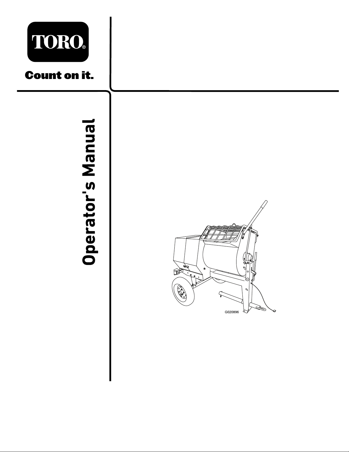
3
A
B
D
g019883
2
3
4
3
1
4
InstallingtheSafetyChain
Partsneededforthisprocedure:
1
Safetychain
2
Connectinglink
InstallingtheSafetyChaintothe
Machine
1.Formahookontheendofabendablepieceofrod
orstiffwire(notincluded),andinsertitthroughboth
keyholesinthefrontpostofthemachine(Figure4).
AdjustingtheMixingPaddles
NoPartsRequired
Procedure
Ifthemixingpaddlesandwipersneedadjustment,adjustthe
paddlesandwipers;refertoAdjustingthePaddles(page42)
Figure4
1.Keyhole
2.Rodorwire(notincluded)4.Connectinglink
2.Attachthesafetychaintothelengthofrodorwire
(Figure4).
3.Pulltherod,orwire,andthesafetychainthroughboth
keyholes(Figure4).
Note:Ensurethatapproximatelyequallengthsof
safetychainextendfromeithersideofthefrontpost.
3.Safetychain
InstallingtheConnectingLinks
1.Aligntheconnectinglinktothelastlinkinoneendof
thesafetychain(Figure4).
2.Inserttheconnectinglinkthroughthechainlinkuntil
theconnectinglinksnapsclosed(Figure4).
3.Repeatsteps1and2toinstalltheotherconnectinglink
intheotherendofthesafetychain.
9
Page 10

ProductOverview
G020897
1
2
3
4
5
6
8
9
10
12
13
14
15
16
7
11
17
18
G022173
1
2
3
4
67
8
9
10
11
12
13
5
14
15
15
16
G022174
13
1
2
3
4
5
6
7
8
9
10
11
12
14
Figure5
Rightside(Models68017Cand68021C)
1.Rearcowl
2.Frontcowl8.Drumlatch
3.Grate
4.Bagsplitter10.T owpole16.Wheel
5.Dumphandle11.Lightingwire
6.Grateliftarm12.Safety-chain
7.Clutchlever
9.Frontpost15.Axle
harness
keyhole
13.Drum
14.Chute
assembly
17.Light(2)
18.Cowllatch
Leftside(Model68024C)
1.Dumphandle
2.Bagsplitter8.Wheel
3.Grate9.Clutchlever
4.Frontcowl10.Drum
5.Rearcowl11.T owpole
6.Cowllatch
7.Light(2)13.Safety-chain
assembly
12.Lightingwire
harness
Figure7
keyhole
14.Frontpost
15.Drumlatch
16.Grateliftarm
1.Dumphandle
2.Drum7.Towpole
3.Drumlatch
4.Frontpost
5.Lightingwire
harness
Rightside(Model68024C)
6.Safety-chain
8.Grateliftarm
9.Chute
10.Wheel
Figure6
keyhole
assembly
11.Light(2)
12.Cowllatch
13.Rearcowl
14.Frontcowl
15.Grate
10
Page 11

Controls
G019875
1
1
G019874
1
G019877
G019878
1
Becomefamiliarwithallthecontrolsbeforeyoustartthe
engineandoperatethemachine.
ClutchLever
Theclutchleverengagesanddisengagesenginepowertothe
paddles.
•Belt-drivemodels(models68017Cand68021C)
DrumLatch
Thedrumlatchsecuresthedrumtothemixposition(upright)
formixingoperationsandwhentransportingthemachine.
Figure10
1.Drumlatch
DumpHandle
1.Clutchlever
•Gear-casemodel(model68024C)
Belt-drivemodels
Gear-casemodel
Figure8
Figure9
Usethedumphandletorotatethedrumtothedumpposition
andtorotatethedrumtothemixposition(upright).
Figure11
1.Dumphandle
1.Clutchlever
11
Page 12
EngineControls
1
2
3
4
5
6
7
8
G019744
1
2
3
G018792
OFF
ON
1
OFF
ON
G021 103
2
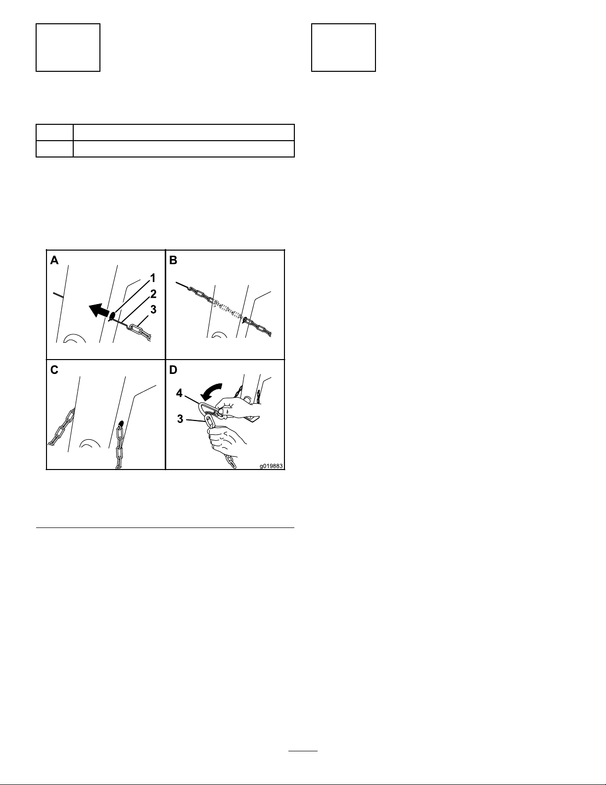
Figure12
1.Recoil-starthandle5.Fuelcap
2.Fuelvalve
3.Chokelever7.Oil-drainplug
4.Throttlelever
6.Oilcap/dipstick
8.On/Offswitch
ChokeLever
Usethechokelever(Figure13)tostartacoldengine.Before
pullingtherecoil-starthandle,movethechokelevertothe
closedposition.Oncetheengineisrunning,movethechoke
levertotheopenposition.Donotusethechokeiftheengine
isalreadywarmeduportheairtemperatureishigh.
ThrottleLever
Thethrottlelever(Figure13)controlsthespeed(rpm)ofthe
engine.Itislocatednexttothechokelever.Itsetstheengine
speedandthereforecanincreaseanddecreasetherotation
speedofthemixingpaddles.Forbestperformance,setthis
controltothefastpositionwhenmixingmaterial.
EngineOn/OffSwitch
TheON/OFFswitch(Figure14)allowstheoperatorofthe
machinetostartandshutofftheengine.Thisswitchis
locatedonthefrontoftheengine.RotatetheON/OFFswitch
totheONpositiontostartandruntheengine.Rotatethe
ON/OFFswitchtotheOFFpositiontoshutofftheengine.
FuelValve
Thefuelvalve(Figure13)islocatedunderneaththechoke
lever.MovetheleverforthefuelvalvetotheONposition
beforeattemptingtostarttheengine.Whenyouhavenished
mixing,shutofftheengineandmovethefuel-valveleverto
Figure14
theOFFposition.
1.OFFposition2.ONposition
Recoil-StartHandle
Tostarttheengine,pulltherecoil-starthandle(Figure12)
quicklytoturntheengineover.Theenginecontrolsdescribed
abovemustallbesetcorrectlyfortheenginetostart.
Oil-LevelSwitch
Theoil-levelswitchislocatedinsidetheengine,anditdoes
notallowtheenginetorunintheeventtheoillevelisbelow
thesafeoperatinglimit.
Figure13
1.Fuelvalve3.Throttlelever
2.Chokelever
12
Page 13

Specications
Note:Specicationsanddesignaresubjecttochangewithoutnotice.
MachineSpecications
Model
BatchCapacity0.17cubicm(6.0cubicft)0.23cubicm(8.0cubicft)0.34cubicm(12.0cubicft)
TotalVolume
DrumMaterialPolyethylenePolyethylene
Length
(withouttowpole)
Width86cm
Height137cm
Weight241kg
Axle
Engine
Drivebeltbeltgearbox
68017C68021C68024C
0.20cubicm(6.9cubicft)0.25cubicm(9.0cubicft)0.42cubicm(14.8cubicft)
Steel
163cm
(64inches)
(34inches)
(54inches)
(530lb)
86to117cm(34to46inches)
extendable
®
Honda
GX240Honda
193cm
(86inches)
86cm
(34inches)
137cm
0(54inches)
266kg
(585lb)
86to117cm(34to46inches)
extendable
®
GX240Honda
205.7cm
(81inches)
142.2cm
(50inches)
150cm
(59inches)
508kg
(1120lb)
142cm(56inches)
xed
®
GX340
Attachments/Accessories
AselectionofT oroapprovedattachmentsandaccessoriesisavailableforusewiththemachinetoenhanceandexpandits
capabilities.ContactyourAuthorizedServiceDealerorDistributor.
TobestprotectyourinvestmentandmaintainoptimalperformanceofyourToroequipment,countonTorogenuineparts.
Whenitcomestoreliability,Torodeliversreplacementpartsdesignedtotheexactengineeringspecicationofourequipment.
Forpeaceofmind,insistonT orogenuineparts.
13
Page 14

Operation
G009027
1
2
G019741
ThinkSafetyFirst
Carefullyreadallsafetyinstructionsandsymbolsinthe
safetysection.Knowingthisinformationcouldhelpyouor
bystandersavoidinjury.
CAUTION
Thismachineproducessoundlevelsthatcancause
hearinglossthroughextendedperiodsofexposure.
Wearhearingprotectionwhenoperatingthis
machine.
Theuseofprotectiveequipmentforeyes,ears,hands,feet,
andheadisrecommended.
Figure15
1.Wearsafetyglasses.
2.Wearhearingprotection.
PreparingtoTowtheMachine
Important:Ensurethatyourtowvehiclehastowing
capacityfortheweightofthemachine.
Important:UseaClass2orlargerreceiver.
Note:Ensurethatyourtowvehiclehastheappropriatehitch
totowthemachine;optionsincludea50mm(2inch)ball
hitchorapintlehitch.
Figure16
5.Extendtheaxle(Modelsand68021C);referto
ExtendingtheAxle—Belt-DriveModels(page18).
Note:Ensurethattheelectricalconnectorofthetowvehicle
iscompatiblewiththeelectricalconnectorofthemachine.
Themachineusesastandard4-atplug.Ifyourtowvehicle
hasadifferenttypeofplug,obtainanadapterfroman
automotivepartsstore.
1.Ensuretheengineisshutoff,thefuelvalveisoff,and
thedrumisempty.
2.Ifthedrumhasaccumulatedanywater,dumpthe
drum;refertoDumpingtheDrum(page26),steps1,
3,4,and5.
3.Usingthedumplever,positionthedrumsothatitisin
themixposition(upright)andlocked.
4.Closetheenginecowlandsecurethecowllatches
(Figure16).
14
Page 15

CheckingtheTiresandWheels
G020836
1
2
3
4
G021 107
ServiceInterval:Beforeeachuseordaily—Inspectthetires
andwheels.
Aftereachuse—Torquethelugnutsto108to122
N∙m(80to90ft-lb)aftertowing.
WARNING
Failuretomaintaincorrecttirepressuremayresult
intirefailureandlossofcontrol,resultingin
propertydamageandseriousinjuryordeath.
•Checkthetirepressurefrequentlytoensure
properination.Ifthetiresarenotinatedto
thecorrectpressure,theywillwearprematurely.
•Inspectthetireconditionbeforetowingand
afteranyoperatingaccident.
TheDOTtireinformationislocatedontheside
ofeachtire.Thisinformationgivesloadandspeed
ratings.Replacementtiresshouldhavethesame
orbetterratings.Formoreinformationgoto
http://www.nhtsa.gov/Vehicle+Safety/Tires.
2.Ensurethatthetiresareinatedtothecorrectair
pressure.ThefollowingTire-AirPressuretableshows
theappropriateairpressureforthetiresasinstalledat
thefactory.
Important:Alwayschecktheinformation
ontheactualtiresforthecorrectairpressure
requirement.
Important:Themostcommoncauseoftire
troubleisunderination.Maintainfullair
pressure.
TireAirPressure
ModelTirepressure
68017CMax414kPa(60psi)
68021Cand68024CMax241kPa(35psi)
3.Ensurethatthelugnutsaretorquedto108to122
N∙m(80to90ft-lb).Checkthetorqueofthelugnuts
initiallyandaftertowing.
Note:Torquethelugnutsinthesequenceshownin
Figure19.
Note:Thevariousmachinesinthismanualhavedifferent
weights;refertoSpecications(page13)toensurethatthe
tiresonyourmachinemeetorexceedtheweightrequirements
ofyourmachine.
1.Visuallyinspectthetiresfordamageandwear(Figure
17andFigure18)
Figure17
1.Exampleoftirewearcausedbyunderination
Figure19
1.Exampleoftirewearcausedbyoverination
Figure18
15
Page 16

HitchingaMachinewithaStampedBall
A
B
C
G020359
2
1
A
B
D
G019807
5
1
2
3
4
Coupler(optionalkit)
HitchingaMachinewithaForgedBall
Coupler(optionalkit)
1.Applychassisgreasetothesocketofthecouplerand
theareaoftheclampthatcontactstheball.
2.Oilthepivotpointsandslidingsurfacesofthecoupler
withSAE30motoroil.
3.Openthecouplerlatch(Figure20).
1.Applyremovablethread-lockingcompoundtothe
threadsofthecouplerbolttopreventthecoupler
handlefromcomingloose(Figure21).
Important:Applythread-lockingcompoundas
neededinthefuture.
Figure20
1.Bail
4.Positionthecouplerontopofthehitchball(Figure20).
5.Closethecouplerlatch(Figure20).
6.Openthebailonthesafetypin,andinsertthepin
7.Rotatethefreeendofthebailovertheendofthesafety
8.Connectthewireplugofthetowvehicletothewire
2.Safetypin
throughtheholeinthelatch(Figure20).
pinthatisprotrudingthroughthelatch(Figure20).
plugofthemachine.
Figure21
1.Couplerhandle
2.Coupler
3.Clamp
4.Bolt
5.Hitchball
2.Applychassisgreasetothesocketofthecouplerand
theareaoftheclampthatcontactstheball.
3.Pushthecouplerboltupthroughthecouplerclamp
andthecouplertop,andconnectthecouplerhandleto
thebolt(Figure21).
4.Positionthecouplersothatthesocketisontopofthe
hitchballandtheclampisundertheball.
5.Turnthecouplerhandleclockwisetothreaditontothe
boltuntilitissecure(Figure21).
Note:Useawrenchtokeeptheboltfromspinning.
6.Connectthewireplugofthetowvehicletothewire
plugofthemachine.
16
Page 17

HitchingaMachinewithaPintleHitch
G019809
A
B
D
G020084
1
2
3
4
Coupler(optionalkit)
1.Removethepinfromthepintlehitchandopenit
(Figure22).
Figure22
2.Positiontheringonthetowpoleontothehookofthe
pintlehitch(Figure22).
3.Closethetopofthepintlehitchandsecureitwiththe
pin(Figure22).
4.Connectthewireplugofthetowvehicletothewire
plugofthemachine.
HitchingaMachinewithaPinHitch
Coupler(optionalkit)
1.Positionthefrontofthepin-hitchcouplersothatit
islocatedbetweenthetopandbottomplatesofthe
pin/clevishitchofthetowvehicle,andensurethatthe
holesarealigned(Figure23).
Figure23
1.Hitchpin3.Pin-hitchcoupler
2.Hairpincotter
2.Inserta19mm(3/4inch)or22mm(7/8inch)hitch
pinthroughtheholesinthecouplerandthereceiver
hitch(Figure23).
3.Insertahairpincotterthroughtheholeinthebottom
ofthehitchpin(Figure23).
4.Connectthewireplugofthetowvehicletothewire
plugofthemachine.
4.Pin/clevis-hitchreceiver
ConnectingtheSafetyChainstothe
TowVehicle
Connectthesafetychaintothemachineandthetowvehicle
asfollows:
1.Pullthesafetychainthroughtheslotsinthekeyholes
locatedinthefrontpostofthemachine,sothatthe
lengthsoneachsideareequal(Figure24).
2.Crossbothlengthsofchainunderthetowpole.
Note:Crossingthechainsdecreasesthechancesof
thefrontofthemachinedroppingtothegroundifthe
hitchdoesnotholdtheconnection.
17
Page 18

1
2
3
G021 177
Figure24
G021 178
1
2
3
G020828
1.Connectinglinks3.Chaincrossedundertow
pole
2.Keyholesinfrontpost
3.Connecteachlengthofchaintothesafety
chain-mountingpointonthetowvehiclewiththe
connectinglinks(Figure25).
Important:Ensurethatthechainhasenough
slackforturningaroundcornerswhentowingthe
machine.
Figure26
Note:Themachineusesastandard4-atplug.Ifyourtow
vehiclehasadifferenttypeofplug,obtainanadapterfroman
automotive-partsstore.
Important:Routinelycheckthelightstoensurethat
theyareworkingproperly,includingthetaillights,brake
lights,andeachappropriateturnsignal.
CheckingtheLights
•Ensurethatthetaillightsofthemachineilluminatewhen
youturnontheheadlightsoftowvehicle.
•Ensurethatthebrakelightsofthemachineilluminate
whenyoupressthebrakepedalofthetowvehicle.
•Ensurethattheappropriateturnsignalasheswhenyou
operatethecorrespondingturnsignalofthetowvehicle.
ExtendingtheAxle—Belt-Drive
Note:Stowtheexcesschaininsidethebottomofthe
frontpostbypushingitintothekeyholesandlatching
theappropriatelinksintothekeyholeslots.
Models
Models68017Cand68021C
WARNING
Themachineisnotstablewhentowingitwiththe
axleinthenarrowposition.
Towthemachinewiththeaxleinthewideposition.
Important:Adjusttheaxletothenarrowpositiononly
tomovethemachinethroughanarrowaccesspoint,
suchasthegateofafenceorthedoorwayofabuilding.
PreparingtoChangetheAxleWidth
1.Movethemachinetoaleveljob-sitesurface.
2.Disconnectthemachinefromthetowvehicle.
Figure25
1.Connectinglink3.Chainlink
2.Safetychainmounting
pointontowvehicle
3.Ensurethatthemachineissecurefrommovement
beforeyouuseit.
4.Ensurethatthedrumisemptyandinthemixposition
(upright).
ConnectingtheLightingWireHarness
Connecttheelectricalplugofthemachinewiththeelectrical
plugofthetowvehicle,asshowninFigure26.
5.Ensurethatthedrumlatchisengagedandthatthe
drumdoesnotrotatetowardthedumpposition.
18
Page 19

AdjustingtheAxleWidth
G020019
1
1 2
3
4
3
5
6
5
G020020
WARNING
Mechanicalorhydraulicjacksmayfailtosupport
themachineandcauseseriousinjury .
Usejackstandswhensupportingthemachine.
1.Alignajackwithanadequateliftheightandweight
capacityundertheaxle;refertoSpecications(page
13).
•Slideeachsideoftheaxleinwardtothenarrow
position(Figure28).
•Slideeachsideoftheaxleoutwardtothewide
(tow)position(Figure28).
6.Aligntheholesoftheinneraxlewiththeholesofthe
outeraxle.
7.Inserttheboltsthroughtheaxleholes(Figure28).
8.Threadthenutsontothebolts,andtorquethenuts
to87N∙m(64ft-lb).
2.Liftthemachineuntilthetiresareofftheground.
3.Useajackstandateachsupportpointontherear
frameextension(Figure27).
Figure27
1.Supportpoint(2)
4.Removetheboltsandnutsthatsecuretheinneraxleto
theouteraxle(Figure28).
TowingtheMachine
WARNING
Towingthemachineathighspeedincreasesthe
riskofahitchmalfunctionandtirefailure.Higher
speedsalsoincreasethemomentumofthemachine
andbrakingdistance.Ifthemachinebecomes
detachedfromthetowvehicleathighspeed,it
couldcausedamagetoproperty,orinjuryordeath
tobystanders.
Donotexceed88km/h(55mph)whentowingthe
machine.Forpoorroadconditionsorinclement
weather,reducespeedaccordingly.
WARNING
Towingthemachinewithmaterialinthedrum
increasestheriskofahitchmalfunctionandtire
failure.Inaddition,materialcouldbounceoutof
thedrumandhitothervehiclesand/orpeople.
Materialinthedrumincreasestheweight,which
affectsmomentumandbrakingdistance.
1.Wideposition(towing)4.Nut(narrowposition)
2.Narrowposition
3.Nut(wideposition)6.Bolt(narrowposition)
5.Aligntheinneraxletothedesiredpositionasfollows:
Figure28
5.Bolt(wideposition)
Donottowthemachinewithmaterialinthedrum.
•ReviewandunderstandSafeOperatingPractices(page5).
•Testthebrakesofthetowvehiclebeforetowing.
•Avoidsuddenstartsandstopswhiletowingthemachine.
PreparingtoUsetheMachine
•Reviewallofthesafetydecalsonthemachine.
•Useahard-hat,hearingprotection,ashirtwithlong
sleevesbuttonedatthewrists,tight-ttinggloveswithout
drawstringsorloosecuffs,eyeprotection,andadust
maskorrespirator.Ameshvisoralonedoesnotprovide
sufcienteyeprotection;supplementwithprotective
glasses.
•Ensurethatyouarefamiliarwiththesafetyregulations
andshutdownproceduresdescribedintheOperator’s
ManualandtheEngineOwner’sManual.
•Ensurethatallguardsareinplaceandingoodcondition.
19
Page 20

•Ensurethatthepaddlesareinplaceandingood
A
B
D
1
G019879
2
3
4
1
condition.
•Checkthefuelandoillevelsoftheengine.
•Whenpreparingtomixmaterial:
1.Movethemachinetoaleveljob-sitesurface.
2.Removethemachinefromthetowvehicle.
3.Ensurethatthemachineissecurefrommovement
beforeyouuseit.
4.Ensurethatthedrumisinthemixposition
(upright).
5.Ensurethatthedrumlatchisengagedandthatthe
drumdoesnotrotatetowardthedumpposition.
OpeningandClosingtheCowl
4.Rotatetherearcowlupandforwarduntilitisfully
positionedontopofthefrontcowl(Figure29).
ClosingtheCowl
1.Rotatetherearcowlrearwardanddownuntilthe
receiveratthebottomcenterofthecowlisalignedwith
theV -ttingandushontheframeofthemachine
(Figure29).
2.Atthebackofthemachine,grasptheringofthelatch
andpullitontothelatchanchorontherearcowl.
3.Atthesideofthemachine,grasptheringofthelatch
andpullitontothelatchanchorontherearcowl.
4.Repeatstep3ontheoppositesideofthemachine
(Figure29).
OpeningtheCowl
1.Atthesideofthemachinewherethefrontcowland
rearcowlmeet,grasptheringofthelatchandpullit
offfromthelatchanchorontherearcowl(Figure29).
AddingFuel
•Forbestresults,useonlyclean,fresh(lessthan30days
old),unleadedgasolinewithanoctaneratingof87or
higher((R+M)/2ratingmethod).
•Ethanol:Gasolinewithupto10%ethanol(gasohol)
or15%MTBE(methyltertiarybutylether)byvolume
isacceptable.EthanolandMTBEarenotthesame.
Gasolinewith15%ethanol(E15)byvolumeisnot
approvedforuse.Neverusegasolinethatcontains
morethan10%ethanolbyvolume,suchasE15
(contains15%ethanol),E20(contains20%ethanol),or
E85(containsupto85%ethanol).Usingunapproved
fuelmaycauseperformanceproblemsand/orengine
damagewhichmaynotbecoveredunderwarranty.
•Donotusefuelcontainingmethanol.
•Donotstorefueleitherinthefueltankorfuelcontainers
overthewinterunlessafuelstabilizerisused.
•Donotaddoiltofuel.
Figure29
1.Latch3.Receiver
2.Latchanchor
2.Repeatstep1ontheoppositesideofthemachine.
3.Atthebackofthemachinewheretherearcowlmeets
theframeofthemachine,grasptheringofthelatch
andpullitofffromthelatchanchoronthecowl
(Figure29).
4.V-tting
20
Page 21

DANGER
WARNING
Incertainconditions,fuelisextremelyammable
andhighlyexplosive.Areorexplosionfromfuel
canburnyouandothersandcandamageproperty.
•Fillthefueltankoutdoors,inanopenarea,when
theengineiscold.Wipeupanyfuelthatspills.
•Neverllthefueltankinsideanenclosedtrailer.
•Donotllthefueltankcompletelyfull.Add
fueltothefueltankuntilthelevelis6to13mm
(1/4to1/2inch)belowthebottomoftheller
neck.Thisemptyspaceinthetankallowsthe
fueltoexpand.
•Neversmokewhenhandlingfuel,andstayaway
fromanopenameorwherefuelfumesmaybe
ignitedbyaspark.
•Storethefuelinanapprovedcontainerandkeep
itoutofthereachofchildren.Neverbuymore
thana30-daysupplyoffuel.
•Donotoperatewithoutentireexhaustsystemin
placeandinproperworkingcondition.
Fuelisharmfulorfatalifswallowed.Long-term
exposuretovaporscancauseseriousinjuryand
illness.
•Avoidprolongedbreathingofvapors.
•Keepfaceawayfromnozzleandfueltankor
conditionerbottleopening.
•Avoidcontactwithskin;washoffspillagewith
soapandwater.
UsingStabilizer/Conditioner
Useafuelstabilizer/conditionerinthemachinetoprovide
thefollowingbenets:
•Keepsfuelfreshduringstorageof90daysorless.For
longerstorageitisrecommendedthatthefueltankbe
drained.
•Cleanstheenginewhileitruns
•Eliminatesgum-likevarnishbuildupinthefuelsystem,
whichcauseshardstarting
Important:Donotusefueladditivescontaining
methanolorethanol.
DANGER
Incertainconditionsduringfueling,static
electricitycanbereleasedcausingasparkwhich
canignitethefuelvapors.Areorexplosionfrom
fuelcanburnyouandothersandcandamage
property.
•Alwaysplacefuelcontainersonthegroundaway
fromyourvehiclebeforelling.
•Donotllfuelcontainersinsideavehicleoron
atruckortrailerbedbecauseinteriorcarpets
orplastictruck-bedlinersmayinsulatethe
containerandslowthelossofanystaticcharge.
•Whenpractical,removegas-poweredequipment
fromthetruckortrailerandrefueltheequipment
withitswheelsontheground.
•Ifthisisnotpossible,thenrefuelsuchequipment
onatruckortrailerfromaportablecontainer,
ratherthanfromafuel-dispensernozzle.
•Ifyoumustuseafuel-dispensernozzle,keepthe
nozzleincontactwiththerimofthefueltank
orcontaineropeningatalltimesuntilfuelingis
complete.
Addthecorrectamountofgasstabilizer/conditionerto
thegas.
Note:Afuelstabilizer/conditionerismosteffective
whenmixedwithfreshfuel.T ominimizethechanceof
varnishdepositsinthefuelsystem,usefuelstabilizerat
alltimes.
21
Page 22

FillingtheFuelTank
1
G019799
G020679
1
Model(s)
68017Cand68021C5.3L(1.40USgallons)
68024C6.1L(1.61USgallons)
Fueltankcapacity
1.Parkthemachineonalevelsurface,shutofftheengine,
andallowtheenginetocool.
2.Cleanaroundthefuelcapandremoveit(Figure30).
Figure30
1.Fuelcap
3.Addunleadedgasolinetothefueltank,untilthelevel
isatthebottomofthemaximumfuellevel,asshown
inFigure31.
Important:Thisspaceinthetankallowsfuelto
expand.Donotllthefueltankcompletelyfull.
Figure31
1.Maximumfuellevel
4.Installthefuelcapsecurely(Figure30).
5.Wipeupanyfuelthatmayhavespilled.
CheckingtheEngine-OilLevel
ServiceInterval:Beforeeachuseordaily
Important:Use4-cycleengineoilthatmeetsorexceeds
therequirementsforAPIservicecategory
or higher
Model(s)Crankcasecapacity
68017C,68021C,and68024C1.1L(1.2USqt)
.
Important:Iftheoillevelinthecrankcaseistoolow
ortoohighandyouruntheengine,youmaydamage
theengine.Thistypeofdamageisnotcoveredbythe
warranty.
Note:UseSAE10W-30forgeneraluse.Youcanuse
theotherviscositiesshowninthechartwhentheaverage
temperatureinyourareaiswithintheindicatedrange(Figure
32).
SJ , SL, SM,
22
Page 23

g013375
0 20 40 60 80 100 F
-20 -10 0 10 20 30 40 C
o
o
30
5W - 30 / 10W - 30
Figure32
G019815
1
2
3
1.Placethemachineonaat,levelsurface,andshutoff
theengine.
2.Allowtheenginetocool.
3.Cleanaroundtheoildipstick.
4.Removetheoil-llcap/dipstickandwipetheendclean
(Figure33).
Figure34
Figure33
1.Fillport
2.Dipstick
3.Oil-levelupperlimit
4.Oil-levellowerlimit
5.Slidethedipstickfullyintothellportwithout
threadingitintotheport(Figure33).
6.Removethedipstickandlookattheend.Ifthe
engine-oillevelislow ,slowlypouronlyenoughoilinto
thellporttoraisetheleveltotheFullmarkonthe
dipstick(Figure33).
Note:ToroPremiumEngineOilisavailablefrom
yourAuthorizedToroDealer.
1.Chokelever
2.Fuelvalve
3.Throttlelever
2.MovetheleverofthefuelvalvetotheONposition—all
thewaytotheright(Figure34);refertoFuelValve
(page12).
3.Positionthechokeleverasfollows:
•Tostartacoldengine,movethechokelevertothe
CLOSEDposition—allthewaytotheleft(Figure
34);refertoChokeLever(page12).
•Tostartawarmengine,movethechokeleverin
theOPENposition—allthewaytotheright.
4.RotatetheengineswitchtotheONposition(Figure
34);refertoEngineOn/OffSwitch(page12).
5.Pulltherecoil-starthandlelightlyuntilyoufeel
resistance,thenpullthehandlebriskly.Returnthe
recoil-starthandlegently(Figure35).
7.Replaceandsecurethedipstick(Figure33).
StartingandShuttingOffthe Engine
StartingtheEngine
1.Ontheengine,movethethrottleleverawayfromthe
MINposition,1/3ofthewaytowardtheMAXposition
(Figure34);refertoThrottleLever(page12).
23
Page 24

G019747
Figure35
G019873
1
2
Note:IfthechokeleverissettotheCLOSEDpositionto
starttheengine,graduallymovethechokeleverbacktoward
theOPENpositionastheenginewarmsup.Iftheengine
stallsorhesitates,movethechokeleverbacktowardthe
CLOSEDpositionuntiltheenginerunssmooth.Allowthe
enginetowarmup,thenmovethechokelevertotheOPEN
position;refertoChokeLever(page12).
Usetheclutchlevertocontrolthepowertransmissiontothe
paddlesofthemachine.
ControllingthePaddles—Belt-drive
Models
Models68017Cand68021Conly
ShuttingOfftheEngine
WARNING
Inanemergencysituation,shutofftheengine
immediately.
Important:Duringnormaloperation,iftheengine
hasbeenworkinghardorishot,letitidleforaminute
beforeshuttingofftheengine.Thishelpstocoolthe
enginebeforeshuttingoff.
1.EnsurethatthechokeleverisintheOFFposition
(Figure34);refertoChokeLever(page12).
2.MovethethrottlelevertotheMINposition(Figure
34);refertoThrottleLever(page12).
3.RotatetheengineswitchtotheOFFposition;referto
EngineOn/OffSwitch(page12).
ControllingthePaddles
DANGER
Thismachineiscapableofamputatinghands.
•Stayintheoperator’spositionwhilethemachine
isrunning.
•Keepallbystandersasafedistancefromthe
machine.
•Stopthemachineimmediatelyifanypeopleor
animalsentertheworkarea.
•Neverplaceanypartofyourbodyintoaposition
thatcausesanunsafeoperatingcondition.
Figure36
1.Offposition2.Onposition
24
Page 25

ControllingthePaddles—Gear-case
1
2
G019872
A
B
D
G019973
Model
Model68024Conly
Figure37
1.Onposition2.Offposition
MixingtheMaterial
DANGER
Eyeandskincontactwithconcretematerialsand
breathingthedustinvolvedishazardoustoyour
health.
MixingaBatchofMaterialinthe
Machine
1.Ensurethatthereisnoold,loosematerialinthedrum
thatcancontaminatethebatchofmaterial;referto
CleaningtheDrum(page26)andDumpingtheDrum
(page26),thenreturnthedrumtotheuprightposition.
Note:Ensurethatthedrumisinthemixposition
(upright)andthedrumlatchisengaged.
2.MovetheclutchlevertotheOFFposition;referto
ControllingthePaddles(page24).
3.Starttheengine;refertoStartingtheEngine(page23).
Note:Allowtheenginetowarm-upat2/3throttle
for1to2minutes.
4.SetthethrottleleverontheenginetotheMAXposition;
refertoThrottleLever(page12).
5.MovetheclutchlevertotheONposition;referto
ControllingthePaddles(page24).
6.Addtheingredientsforthebatchasfollows:
A.Pourwaterintothedrumthroughthegratingof
thedrumguard.
B.Addtheplaster,cement,orotherbindingmaterial.
Note:Youcanopenbagsofcement,plaster,and
bindingmaterialsbyloweringthebagontothe
bagsplitter(Figure38).
•Ensurethatthereisadequateairventilation.
•Wearadustmasktopreventinhalationofdust
whileusingthemachine;refertoSafeOperating
Practices(page5).
•Avoiddirectcontactofcementandconcrete
materialswithskinandeyes.
DANGER
Contactwiththemixingpaddlescouldcause
damageorinjury.
Neverputyourhandsortoolsinsidethedrumwhile
theengineisrunning.
Important:Donotaddmorematerialthanthebatch
capacityofthemachine;refertoSpecications(page13).
Note:Followthemanufacturer’sinstructionsthatareprinted
onthepackagingoftheproductyouareusing.
Figure38
C.Ifyouareusingsandand/orotherreinforcing
materials,addthemintothedrum.
7.Allowthepaddlestomixthematerialuntilthe
ingredientshaveauniformappearance.
Note:Ifneeded,addwaterorplaster,cement,or
otherbindingmaterialuntiltheconsistencyofthe
batchiscorrect.
25
Page 26

8.Releasethedrumlatchanddumpthedrum;referto
1
2
3
4
G019972
DumpingtheDrum(page26).
UsingtheDrum
DANGER
Note:Allowthemachinetocompletelydischargethe
contentsofthedrum.
5.Rotatethedumphandleclockwiseuntilthedrum
latchlocksthedrumintheuprightposition(Figure39).
6.Afterdischargingabatchofmaterial,cleanthedrum;
refertoCleaningtheDrum(page26).
Contactwiththemixingpaddlescouldcause
damageorinjury.
Neverputyourhandsinsidethedrumwhilethe
engineisrunning.
DumpingtheDrum
Note:Whendumpingabatchofmaterial,leavetheengine
runningandtheclutchintheONpositionsothattherotating
paddleshelpdischargethematerial.
1.Alignawheelbarroworsimilarcontainerofadequate
capacityinthepathofthedrumopening.
2.Graspthedumphandlewithyourlefthand(Figure39).
Note:Thisstepcleansthepaddlesanddrumbetween
batchesandpreventdriedmaterialfromforming,and
contaminatingthenextbatchofmaterial.
CleaningtheDrum
Important:Donotstrikeonthedrumwithashovel,
hammer,oranyotherdevicetoloosenanyaccumulated
driedmaterials.
1.Stoptherotationofthepaddlesbymovingtheclutch
levertotheOFFposition;refertoControllingthe
Paddles(page24).
2.RotatetheengineON/OFFswitchtotheOFFposition;
refertoShuttingOfftheEngine(page24).
3.Ensurethatthedrumisinthemixposition(upright);
refertoDumpingtheDrum(page26),step5.
4.Spraythemachinewithwatertoremoveany
accumulatedmaterial.
5.Starttheengine;refertoStartingtheEngine(page23).
6.Starttherotationofthepaddlesbymovingtheclutch
levertotheOnposition;refertoControllingthe
Paddles(page24).
Figure39
1.Dumphandle(mix
position)
2.Drumlatch(release
position)
3.Drumlatch(locked
position)
4.Dumphandle(dump
position)
Note:Whendumpingabatchofmaterial,aligna
wheelbarroworasimilarcontainerofadequatecapacity
beneaththechute.
3.Liftthehandleofthedrumlatch(Figure39).
4.Withbothhandsonthedumphandle,rotateit
counterclockwisetodischargethecontentsofthe
drum(Figure39).
7.Dumpthedrum;refertoDumpingtheDrum(page
26).
26
Page 27

Maintenance
Important:Beforeperforminganymaintenanceprocedures,rstshutofftheengine,wait5minutestoallowall
movingpartstocometoacompletestopandcool,anddisconnectthespark-plugwire.
RecommendedMaintenanceSchedule(s)
MaintenanceService
Interval
Aftertherst25hours
Beforeeachuseordaily
Aftereachuse
Every40hours
Every50hours
Every100hours
Every300hours
MaintenanceProcedure
•Changetheengineoil.
•Checkthegear-caseclutch(Model68024Conly).
•Inspectthebeltsandadjustasnecessary.
•Inspectthetiresandwheels.
•Checktheengine-oillevel.
•Inspecttheair-cleanerelements.
•Checktheclutchoperation(Model68024Conly).
•T orquethelugnutsto108to122N∙m(80to90ft-lb)aftertowing.
•Cleanthedrumbetweenmixingbatchesofmaterial.
•Lubricatethetrunnions.
•Cleanthemachine.
•Checkthegear-caseoil(Model68024Conly).
•Inspectthebeltsandadjustasnecessary.
•Checktheclutchoperation(Models68014C,68017C,and68021Conly).
•Cleantheair-cleanerelements.Cleanthemmorefrequentlyindustyoperating
conditions.
•Changetheengineoil.
•Checkthesparkplug.
•Cleanthesparkarrester.
•Cleanthesedimentcup.
•Replacethepaperair-cleanerelement.Replaceitmorefrequentlyindusty
operatingconditions.
•Replacethesparkplug.
Every800hours
Monthly
Yearlyorbeforestorage
Every2years
•Replacethegear-caseoil(Model68024Conly).
•Lubricatethepillow-blockbearings.
•Cleanthefuel-sedimentcup.
•Replacethebelts.
Important:Refertoyourengineoperator'smanualforadditionalmaintenanceprocedures.
27
Page 28

Premaintenance
G019281
1
G020752
G020753
Procedures
PreparingtheMachinefor Maintenance
1.Parkthemachineonalevelsurface.
2.Removethemachinefromthetowvehicle.
3.Ensurethatthemachineissecurefrommovement
beforeyouuseit.
4.Opentherearcowl;refertoOpeningtheCowl(page
20).
5.Ensurethattheengineandmuferarecool.
6.Disabletheengine;refertoDisconnectingthe
Spark-PlugWire(page28).
DisconnectingtheSpark-Plug Wire
Pullthespark-plugwireofftheterminalofthesparkplug
(Figure40).
RemovingtheDividerPlate
1.Unlatchandopenthecowl;refertoOpeningtheCowl
(page20).
2.Useawrenchtoremovethe4boltsthatsecurethe
dividerplatetothefrontcowl.
Note:Keeptheboltsforinstallingthedividerplate.
Figure41
3.Toremovethedividerplate,liftitupwardandrotate
itcounterclockwisesothatitclearsvariousengine
components.
Figure40
1.Sparkplug
RemovingandInstallingthe DividerPlate
Youneedtoremovethedividerplatetoprovideaccessbefore
performingsomemaintenanceprocedures.
Note:Model68024Cdoesnothaveadividerplate.
InstallingtheDividerPlate
1.Guidethedividerplateintopositionagainstthefront
cowl.
Note:Startwiththedividerplaterotatedslightly
counterclockwise,andthenrotateitclockwisewhile
loweringitintoposition.
Ensurethatthedividerplateisnotbackward.
Figure42
2.Aligntheboltholesinthedividerplateandthefront
cowl.
3.Installeachofthe4bolts,andhand-tightenthemto
preventcross-threading.
4.Tightentheboltswithawrenchuntiltheyaresecure.
28
Page 29

Lubrication
2
3
G020684
1
3
G020685
LubricatingtheBearingsand Seals
ServiceInterval:Aftereachuse—Lubricatethetrunnions.
Monthly—Lubricatethepillow-blockbearings.
Note:Thepillow-blockbearingsareinsidethe
cowl—removethedividerplatetoaccessthem;referto
RemovingtheDividerPlate(page28).
Model68024Cdoesnothaveadividerplate.
GreaseType:No.2lithiumgrease.
1.Cleanaroundeachgreasettingwitharagandliftthe
plasticcapoffthegreasetting(Figure43).
2.Pumpgreaseintoeachttingasfollows:
•Forthepillow-blockbearings,pump1shotof
greaseintoeachtting(Figure43).
•Forthetrunnions,pumpseveralshotsofgrease
intoeachttinguntilitstartstooozeoutofthe
bearinghousing(Figure43).
Important:Pumpgreaseinslowlyandcarefully
topreventdamagetothebearingseals.
3.Wipeupanyexcessgrease.
Figure43
1.Pillow-blockbearings3.Fronttrunnion
2.Reartrunnion
29
Page 30

EngineMaintenance
G020216
1
2
3
4
5
6
ServicingtheAirCleaner
ServiceInterval:Beforeeachuseordaily—Inspectthe
air-cleanerelements.
Every50hours—Cleantheair-cleanerelements.Clean
themmorefrequentlyindustyoperatingconditions.
Every300hours/Yearly(whichevercomes
rst)—Replacethepaperair-cleanerelement.Replace
itmorefrequentlyindustyoperatingconditions.
Important:Donotoperatetheenginewithoutthe
air-lterassembly;extremeenginedamagecanoccur.
1.Shutofftheengineandwaitforallmovingpartsto
stop.
2.Disconnectthewirefromthesparkplug;referto
DisconnectingtheSpark-PlugWire(page28).
3.Removethenutthatsecuresthecover(Figure44).
Figure44
1.Covernut
2.Cover
3.Wingnut6.Base
4.Removethecover.
Note:Becarefultopreventdirtanddebrisfrom
fallingintothebase.
5.Removethefoamandpaperelementsfromthebase
(Figure44).
6.Removethefoamelementfromthepaperelement
(Figure44).
7.Inspectthefoamandpaperelements,andreplacethem
iftheyaredamagedorexcessivelydirty.
8.Ifthepaperelementisexcessivelydirty,replaceit.
Note:Nevertrytobrushdirtoffthepaperelement;
brushingforcesthedirtintothebers.
9.Cleanthefoamelementinwarm,soapywaterorin
anonammablesolvent.
4.Foamelement
5.Paperelement
Note:Donotusefueltocleanthefoamelement
becauseitcouldcreateariskofreorexplosion.
30
Page 31

10.Rinseanddrythefoamelementthoroughly.
g013375
0 20 40 60 80 100 F
-20 -10 0 10 20 30 40 C
o
o
30
5W - 30 / 10W - 30
1
2
3
G019750
11.Dipthefoamelementincleanengineoil,thensqueeze
outtheexcessoil.
Note:Excessoilinthefoamelementrestrictstheair
owthroughtheelementandmayreachthepaper
lterandclogit.
12.Wipedirtfromthebaseandthecoverwithamoistrag.
DrainingtheEngineOil
WARNING
Oilmaybehotaftertheenginehasbeenrun,and
contactwithhotoilcancauseseverepersonalinjury.
Avoidcontactingthehotengineoilwhenyoudrain
it.
Note:Becarefultopreventdirtanddebrisfrom
enteringtheairductleadingtothecarburetor.
13.Installtheair-cleanerelementsandensurethattheyare
properlypositioned.
14.Securelyinstallthecoverwiththenut.
ChangingtheEngineOil
ServiceInterval:Aftertherst25hours
Every100hours
ToroPremiumEngineOilisavailablefromyourAuthorized
ToroDealer.
Important:Use4-cycleengineoilthatmeetsorexceeds
therequirementsforAPIservicecategory
or higher
68017C,68021C,and68024C1.1L(1.2USqt)
Important:Iftheoillevelinthecrankcaseistoolow
ortoohighandyouruntheengine,youmaydamage
theengine.Thistypeofdamageisnotcoveredbythe
warranty.
.
SJ , SL, SM,
1.Shutofftheengineandwaitforallmovingpartsto
stop.
2.Disconnectthewirefromthesparkplug;referto
DisconnectingtheSpark-PlugWire(page28).
3.Placeadrainpanunderthedrainholeoftheengine
(Figure46).
Note:UseSAE10W-30forgeneraluse.Youcanuse
theotherviscositiesshowninthechartwhentheaverage
temperatureinyourareaiswithintheindicatedrange(Figure
45).
Figure45
Figure46
1.Drainplug3.Drainpan
2.Drainhole
4.Removethedrainplugandcatchtheoilinthedrain
pan(Figure46).
5.Whentheoilhasdrainedcompletely,installthedrain
plugwithanewwasher(Figure46).
Note:Disposeoftheusedoilatacertiedrecycling
center.
FillingtheEngineCrankcasewithOil
1.Removethedipstick(Figure47)andslowlypouroil
intothellholeuntiltheoilreachestheupper-limit
mark(bottomedgeoftheoil-llhole)onthedipstick.
31
Page 32

Figure47
G019749
G019300
1 2
4
3
1.Oil-llhole3.Oil-levelupperlimit
2.Dipstick
4.Oil-levellowerlimit
2.Replaceandsecurethedipstick.
3.Wipeupanyspilledoil.
ServicingtheSparkPlug
ServiceInterval:Every100hours/Every6months
(whichevercomesrst)—Checkthe
sparkplug.
Every300hours/Yearly(whichevercomes
rst)—Replacethesparkplug.
Type:NGKBPR6ESorequivalent
Gap:0.7to0.8mm(0.028to0.031inch)
Note:Usea20mm(13/16inch)spark-plugwrenchfor
removingandinstallingthesparkplug.
5.Rotatethesparkplugcounterclockwiseusinga20mm
(13/16inch)spark-plugwrenchtoremovetheplug
andthesealingwasher(Figure49).
Figure49
CheckingtheSparkPlug
Note:Useagappingtool/feelergaugetocheckandadjust
thegap.Installanewsparkplugifnecessary.
1.Lookatthecenterofthesparkplug(Figure50).Ifyou
seelightbrownorgrayontheinsulator,theengineis
operatingproperly.
Important:Nevercleanthesparkplug.Always
replacethesparkplugwhenithasablackcoating,
wornelectrodes,anoilylm,orcracks.
RemovingtheSparkPlug
1.Parkthemachineonalevelsurfaceandshutoffthe
engine;refertoShuttingOfftheEngine(page24).
2.Ensurethatthemachinesurfacesarecool.
3.Pullthespark-plugwireofftheterminalofthespark
plug(Figure48).
1.Sparkplug
4.Cleanaroundthesparkplug.
Figure50
1.Sideelectrode
2.Centerelectrode4.0.7to0.8mm(0.028to
3.Insulator
0.031inch)gap
2.Useagappingtoolforsparkplugsorafeelergaugeto
measurethegapbetweenthesideelectrodeandcenter
electrode(Figure50).
Figure48
2.Wire
3.Ifthegapisnotwithinthespeciedrange,dothe
following:
A.Ifthegapistoosmall,carefullybendtheside
electrodeawayfromthecenterelectrodeuntil
thegapbetweentheelectrodesis0.7to0.8mm
(0.028to0.031inch).
32
Page 33

B.Ifthegapistoolarge,carefullybendtheside
G019331
10
10
1
2
3
4
5
6
7
8
9
11
12
electrodetowardthecenterelectrodeuntilthe
gapbetweentheelectrodesis0.7to0.8mm(0.028
to0.031inch).
InstallingtheSparkPlug
Important:Ensurethatthegapbetweenthesideand
centerelectrodesiscorrectbeforeinstallingthespark
plug.
1.Threadthesparkplugclockwiseintothespark-plug
holebyhand.
Note:Avoidcross-threadingthesparkplugwiththe
threadsofthespark-plughole.
2.Rotatesparkplugclockwiseusinga20mm(13/16
inch)spark-plugwrenchuntiltheplugandsealing
washerareseated(Figure49).
ServicingtheSparkArrester
CleaningtheSparkArrester
ServiceInterval:Every100hours
Note:Asparkarresterisavailableasanoption.Ifyou
requireasparkarrester,contactyourAuthorizedToroService
Dealer.
GenuineT orosparkarrestersareapprovedbytheUSDA
ForestryService.
WARNING
Iftheenginehasbeenrunning,themuferwillbe
hot.
1.Removethedividerplate;refertoRemovingthe
DividerPlate(page28).
3.Tightenthesparkplugasfollows:
•Wheninstallinganin-servicesparkplug,tighten
thepluganadditional1/8to1/4turn.
•Wheninstallinganewsparkplug,tightentheplug
anadditional1/2turn.
4.Pushthespark-plugwireontotheterminalofthespark
plug(Figure48).
Note:Model68024Cdoesnothaveadividerplate.
2.Removethe2nuts(8mm)andremovethemufer
fromthecylinder(Figure51).
Figure51
1.Deector(if
applicable)
2.Protector6.Nut,8mm
3.Screw(6mm)7.Gasket
4.Mufer8.Bolt(8mm)12.Screw(4mm)
3.Removethe3screws(4mm)fromtheexhaust
deectorandremovethedeector(Figure51).
4.Removethescrews(5mmand6mm)fromthemufer
protector,andremovethemuferprotector(Figure
51).
5.Removethescrew(4mm)fromthesparkarresterand
removethesparkarresterfromthemufer(Figure51).
5.Exhaustpipe
9.Sparkarrester
10.Screws(5mm)
11.Exhaustport
33
Page 34

6.Useabrushtocarefullyremovecarbondepositsfrom
1
2
G019332
3
2
4
1
5
G0201 19
G020120
1
2
3
5
6
4
thespark-arresterscreen(Figure52).
Note:Replacethesparkarresterifithasbreaksor
holes.
Figure53
Figure52
1.Screen
2.Brush
7.Installthesparkarrester,muferprotector,exhaust
deector,andmuferinthereverseorderof
disassembly.
8.Installthedividerplate;refertoInstallingtheDivider
Plate(page28).
RemovingandInstallingthe Engine
Models68017Cand68021Conly
RemovingtheEngine
WARNING
Thespringisundertensionwheninstalledandcan
causepersonalinjury.
1.Anchorbracket
2.Enginedeck
3.Spring-removaltool(Toro
part92-5771)
4.Spring-removaltool
(springremoved)
5.Spring(springremoved)
7.Removetheboltandnutthatsecuretherearbracket
fortheengine-deckhingetotheframeofthemachine
(Figure54).
Becarefulwhenremovingthespring .
1.Parkthemachineonalevelsurfaceandshutoffthe
engine;refertoDisconnectingtheSpark-PlugWire
(page28).
2.Ensurethattheengineandtheexhaust-systemsurfaces
arecool.
3.Removethedividerplate;refertoRemovingand
InstallingtheDividerPlate(page28).
4.Removethebeltguide;refertoRemovingtheBelts
(page39).
5.Removethebelts;refertoRemovingtheBelts(page
39).
6.Usingaspring-removaltool(T oropart92-5771),
removethespringfromtheanchorbracketonthe
enginedeck(Figure53).
Note:Leavetheotherendofthespringattachedto
theframeofthemachine.
Figure54
1.Enginedeck4.Frame
2.Pivot5.Nut
3.Rearhingebracket6.Bolt
8.Liftupontherearedgeoftheenginedeckandremove
thehingebracket(Figure54).
9.Slidetheenginedeckrearwardandoutfromthe
forwardhingebracket(Figure55).
Note:Donotremovetheforwardhingebracket.
34
Page 35

G020121
Figure55
2
3
4
1
G019333
10.Removetheengineandenginedeckfromthemachine
(Figure55).
InstallingtheEngine
1.Aligntheengineandenginedecktotherearframeof
themachine.
FuelSystem
Maintenance
ServicingtheFuelSystem
CleaningtheSedimentCup
ServiceInterval:Every100hours/Every6months
(whichevercomesrst)—Cleanthe
sedimentcup.
Yearlyorbeforestorage—Cleanthefuel-sedimentcup.
Underneaththefuelvalveisasedimentcuptocatchdirtin
thefuel.
1.Parkthemachineonalevelsurfaceandshutoffthe
engine;refertoShuttingOfftheEngine(page24).
2.Ensurethattheengineandtheexhaust-systemsurfaces
arecool.
3.Movethefuel-valvelevertotheOFFposition,allthe
waytotheleft(Figure56).
4.Unscrewthesedimentcup(Figure56).
5.RemovethefuellterandO-ring(Figure56).
Note:DonotmisplacetheO-ring.
Note:Thedrivepulleyontheenginemustalign
forward.
2.Alignthepivotontheenginedeckwiththeforward
hingebracket(Figure55).
3.Slidetheenginedeckforwardandthepivotintothe
forwardhingebracket(Figure55).
4.Aligntherearhingebracketwiththepivotonthe
engine-deckhinge(Figure55).
5.Liftupontherearedgeoftheenginedeckandslipthe
hingebracketontothepivot.
6.Securetherearbrackettotheframeofthemachine
usingtheboltandnut(Figure54)removedinstep7of
RemovingtheEngine(page34).
7.Usingaspring-removaltool,(T oropart92-5771),
installthetensionspringtotheanchorbracketonthe
enginedeck(Figure53).
8.Installthebeltsandbeltguide;refertoReplacingthe
Belts—Belt-DriveModels(page39).
9.Adjustthebeltguide;refertoAdjustingtheBeltGuide
(page40).
10.Installthedividerplate;refertoRemovingand
InstallingtheDividerPlate(page28).
Figure56
1.Fuelvalve(Off)3.Fuellter
2.O-ring4.Sedimentcup
Note:DonotcleantheO-ringinsolvent.
6.Cleanthefuellterandsedimentcupusinga
nonammablesolvent,anddryitcarefully.
7.WipetheO-ringwithaclean,drycloth.
8.Installthefuellterinthebottomofthecarburetor
(Figure56).
9.AligntheO-ringintothegrooveinthesedimentcup
andinstallthesedimentcuptofuel-valvehousing.
35
Page 36

10.MovetheleverofthefuelvalvetotheONposition(all
1
2
G020122
thewaytotheright)andcheckforleaks.Ifitleaks,
replacetheO-ring.
DrainingtheFuelTank
1.Removetheengine;refertoRemovingtheEngine
(page34).
DriveSystem
Maintenance
ServicingtheGear Case—Gear-CaseModel
2.Removethefuelcapbyrotatingitcounterclockwise.
Figure57
3.Alignadrainpantothehingeoftheenginedeck.
4.Rotatetheengineonthehingesideoftheenginedeck
anddrainthefuelfromthetank.
5.Carefullylowertheengineandenginedeck.
6.Installthefuelcap.
7.Installtheengine;refertoInstallingtheEngine(page
35).
Model68024Conly
CheckingtheClutchOperation
ServiceInterval:Beforeeachuseordaily—Checktheclutch
operation(Model68024Conly).
1.MovetheclutchlevertotheOFFposition;referto
ControllingthePaddles(page24).
2.Starttheengine;refertoStartingtheEngine(page23).
3.Ensurethattheenginethrottleissettothe2/3
position.
4.IfthepaddlesrotatewiththeclutchlevertotheOFF
positiondothefollowing:
A.Shutofftheengine;refertoShuttingOffthe
Engine(page24).
B.Checktheclutch-leverforce;refertoChecking
theClutchLever(page36).
CheckingtheClutchLever
ServiceInterval:Aftertherst25hours—Checkthe
gear-caseclutch(Model68024Conly).
Important:Checkthegear-caseclutchifthepaddles
rotatewhentheclutchleverisintheOFFposition,ifthe
paddlesrotateslowly,oriftheclutchbeginstoslip.
1.EnsurethattheengineisOFF;refertoShuttingOff
theEngine(page24).
2.Locatetheclutchleveratthebackofthemachine;refer
toClutchLever(page11).
3.MovetheclutchlevertotheOFFposition;referto
ControllingthePaddles(page24).
4.Attachaspringscalewitharangeof15to30kg(35to
55lb)tothegripoftheclutchlever(Figure58).
36
Page 37

G022166
1
2
3
Figure58
G019900
1
2
3
1.Springscale3.Clutchlever
2.15to30kg(35to55lb)
5.Usingthespringscale,pulltheclutchhandletotheON
positionasshowninFigure58.
6.Observethespringscalewhilepullingtoseewhatthe
highestpressureiswhenmovingtheclutchhandle
fromtheOFFpositiontotheOnposition(Figure58).
Figure59
Note:Normalclutchpressureis15to30kg(35to
55lb).
7.Iftheclutchpressureisgreaterthanorlessthan
15to30kg(35to55lb),contactanAuthorizedT oro
ServiceDealer.
CheckingtheGear-CaseOil
ServiceInterval:Every40hours—Checkthegear-caseoil
(Model68024Conly).
Important:Iftheoillevelinthegearcaseistoolow
ortoohighandyouruntheengine,youmaydamage
theengineorthegearcase.Thistypeofdamageisnot
coveredbythewarranty .
OilType:SAE90gearoil
Gear-caseCapacity:2.13L(72oz)
1.Locatethegearcasebetweentheengineandthefront
cowl.
2.Attherightsideofthegearcase,examinetheoillevel
inthesightglass(Figure59).
1.Fillplug3.Drainplug
2.Sightglass
3.Iftheoillevelisbelowthebottom1/3ofthesight
glass,addoilasfollows:
A.Removethellplugfromthellportinthe
housingofthegearcase(Figure59).
B.Slowlyaddthespeciedoilintothellportuntil
theoillevelisbetween1/3and1/2ofthesight
glass(Figure59).
C.Cleanthellplug.
D.ApplyPTFEthread-sealingtapetothethreads
oftheplug.
E.Installtheplugintothellportinthehousing
(Figure59).
ReplacingtheGear-CaseOil
ServiceInterval:Every800hours—Replacethegear-case
oil(Model68024Conly).
1.Alignadrainpanwitha3-quartcapacityunderthe
drainplug(Figure59).
2.Removethedrainplugfromthedrainport,and
completelydrainthegear-caseoil(Figure59).
3.Removethellplug(Figure59).
4.Cleanthedrainandllplugs,andapplyPTFE
thread-sealingtapetotheplugthreads.
5.Installthedrainpluginthedrainport(Figure59).
6.Slowlyaddthespeciedoilintothellportuntilthe
oillevelisbetween1/3and1/2ofthesightglass
(Figure59).
7.Installthellpluginthellport(Figure59).
37
Page 38
BeltMaintenance
G019976
1
2
3
4
3
4
3
1
2
3
G020006
ServicingtheBelts—Belt-Drive Models
Models68017Cand68021Conly
InspectingtheBelts
ServiceInterval:Aftertherst25hours—Inspectthebelts
andadjustasnecessary.
Every40hours—Inspectthebeltsandadjustas
necessary.
1.Removethedividerplate;refertoRemovingthe
DividerPlate(page28).
2.MovetheclutchlevertotheOFFposition;referto
ControllingthePaddles—Belt-driveModels(page24).
3.Examinethebeltsforwearordamage.Ifthebeltsare
wornordamaged,replacethem;refertoServicingthe
Belts—Belt-DriveModels(page38).
4.Examinethepulleysforwear,damage,and
misalignment;refertoReplacingtheBelts—Belt-Drive
Models(page39).
5.Installthedividerplate;refertoInstallingtheDivider
Plate(page28).
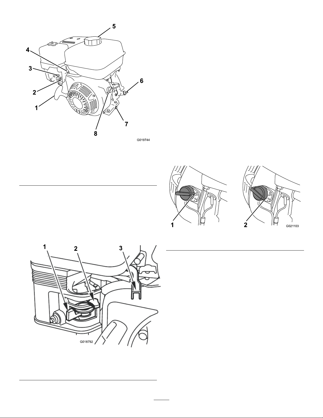
AdjustingtheBeltT ension
Clutchairgap:6to10mm(1/4to3/8inch)
1.MovetheclutchlevertotheONposition;referto
ControllingthePaddles(page24).
2.Measuretheairgapbetweentheenginedeckandthe
rollerontheclutch(Figure60).
Figure60
1.Enginedeck
2.Clutchroller
3.Ifthemeasuredairgapisnotwithinthespecied
range,adjustthegapasfollows:
A.MovetheclutchlevertotheOFFposition;refer
toControllingthePaddles(page24).
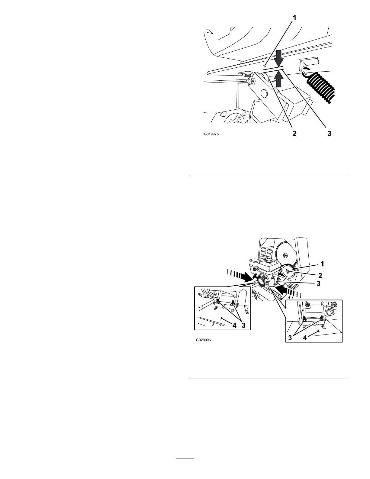
B.Loosenthenutsandboltsthatsecuretheengine
totheenginedeck(Figure61).
3.Clutchairgap:6to10mm
(1/4to3/8inch)
Figure61
1.Idlerpulley3.Nutandbolt
2.Setscrew
C.Movetheenginepositionasfollows:
•Increasetheairgap—movetheengine
awayfromtheidlerpulley(Figure61).
•Decreasetheairgap—movetheengine
towardtheidlerpulley(Figure61).
D.Alignastraightedgeacrosstheenginepulleyand
theidlerpulley(Figure62).
38
4.Enginedeck
Page 39

G020009
1 2
3
4
5
6 7 8
Figure62
2
G020010
2
3
4
1
G020012
Figure63
1.Bolt2.Beltguide
4.Sliptheforwardbeltforwardandofftheidlerpulley
(Figure64).
1.Enginepulley
2.Idlerpulley6.Jamnut
3.Reductioncase(engine)7.Setscrew
4.Beltguide
5.Idlershaft
8.Straightedge
E.Ifneeded,pivottheengineontheenginedeck
untiltheenginepulleyandtheidlerpulleyare
alignedtothestraightedge(Figure62).
F.Tightenthenutsandboltsthatsecuretheengine
totheenginedecktoatorqueof18N∙m(13ft-lb).
G.Checktheairgapbetweentheenginedeckand
therollerontheclutch.Iftheairgapisnotwithin
thespeciedrange,repeatstep3untiltheairgap
measurementiswithinthespeciedrange.
H.Installthedividerplate;refertoInstallingthe
DividerPlate(page28).
Replacingthe Belts—Belt-DriveModels
ServiceInterval:Every2years—Replacethebelts.
Models68017Cand68021Conly
RemovingtheBelts
1.MovetheclutchlevertotheOFFposition;referto
2.Removethedividerplate;refertoRemovingthe
3.Removetheboltthatsecuresthebeltguidetothe
ControllingthePaddles—Belt-driveModels(page24).
DividerPlate(page28).
engine,andremovethebeltguide(Figure63).
Figure64
1.Enginepulley3.Idlerpulley
2.Forwardbelt4.Rearbelt
5.Sliptherearbeltrearwardandofftheidlerpulley
(Figure64).
6.Slipthebeltsofftheenginepulley.
7.Removethebeltsfromthemachine.
InstallingtheBelts
1.EnsurethattheclutchleverisintheOFFposition;
refertoControllingthePaddles—Belt-driveModels
(page24).
2.Aligntherearbelttothereargrooveintheengine
pulley.
Note:Donotaligntherearbelttotheidlerpulley .
3.Aligntheforwardbelttotheforwardgrooveofthe
idlerpulley.
4.Sliptherearbeltovertheidlerpulleyandalignthebelt
totherearpulleygroove.
39
Page 40

5.Sliptheforwardbeltovertheenginepulleyandalign
G02001 1
3 4
5
1
2
thebelttotheforwardpulleygroove.
6.Checkthebelttension;refertostep1,step2,andstep
3inAdjustingtheBeltTension(page38).
7.Looselysecurethebeltguidetotheengine(Figure63)
withtheboltthatwasremovedinstep3ofRemoving
theDividerPlate(page28).
8.Adjustthebeltguide;refertoAdjustingtheBeltGuide
(page40).
9.Installthedividerplate;refertoInstallingtheDivider
Plate(page28).
AdjustingtheBeltGuide
Important:Thebeltguideshouldnot
contactthebeltswiththeclutchleverinthe
ONposition.
Note:Iftheairgapbetweenthebeltguideand
bothbeltscannotbeattained,thenoneofthe
beltsistoolong.
C.Tightentheboltthatsecuresthebeltguidetothe
engine(Figure65).
D.Checktheclutchoperation;refertoControlling
thePaddles(page24).
5.Installthedividerplate;refertoInstallingtheDivider
Plate(page28).
Note:Toaccessthebeltguide,removethedividerplate;
refertoRemovingtheDividerPlate(page28).
Guideairgap:2.5to4.0mm(3/32to5/32inch)
1.EnsurethattheclutchleverisintheONposition;refer
toControllingthePaddles(page24).
2.Ensurethatthebelttensioniscorrect;referto
AdjustingtheBeltGuide(page40).
3.Checkthattheairgapbetweenthebeltguideandthe
beltsis2.5to4.0mm(3/32to5/32inch);referto
Figure65.
CheckingtheClutchOperation
ServiceInterval:Every40hours—Checktheclutch
operation(Models68014C,68017C,
and68021Conly).
Important:Thepaddlesmustnotrotateinanempty
drumwhentheclutchleverisintheOFFposition.
1.MovetheclutchlevertotheOFFposition;referto
ControllingthePaddles(page24).
2.Starttheengine;refertoStartingtheEngine(page23).
3.IfthepaddlesrotatewiththeclutchlevertotheOFF
positiondothefollowing:
A.Shuttingofftheengine;refertoShuttingOffthe
Engine(page24).
B.Checktheairgapbetweenthebeltguideandthe
belts.
Note:Iftheairgapislargerthan4.0mm(0.16
inch),decreasethegapbetweenthebeltguide
andthebelts;refertoAdjustingtheBeltGuide
(page40).
1.Enginepulleys4.Beltguide
2.Belts5.Bolt
3.Guideairgap:2.5to4.0
mm(3/32to5/32inch)
4.Iftheairgapisnotwithinthespeciedrange,dothe
following:
A.Loosentheboltthatsecuresthebeltguidetothe
engine(Figure65).
Important:Ensurethatthebeltguideis
towardtheenginepulley.
B.Rotatethebeltguideupordownuntilthereis
anairgapof2.5to4.0mm(3/32to5/32inch)
betweentheguideandeachbelt(Figure65).
4.Repeatsteps1,2,and3untilallthefollowing
conditionsaremet:
Figure65
•Theengineisrunat2/3throttle.
•TheclutchleverisintheOFFposition;referto
ControllingthePaddles(page24)
•Thepaddlesdonotrotateinanemptydrum.
40
Page 41

Aligningthe
G020015
53 6
1 2
4
A
B
C
E
F
G020829
A
B
C
E
F
G020830
Pulleys—Belt-driveModels
Models68017Cand68021Conly
ReplacingtheLight Bulbs
1.Removethedividerplate;refertoRemovingthe
DividerPlate(page28).
2.Placeastraightedgeacrossthefaceoftheenginepulley
andtheidlerpulley(Figure66).
Figure66
1.Enginepulley
2.Idlerpulley5.Locknut
3.Straightedge6.Setscrew
Note:Bothpulleysmustbealignedushwiththe
straightedge.
4.Idlershaft
ReplacingtheRear-Facing TaillightBulbs
Note:Theleftrear-facingbulbalsoilluminateslicenseplate.
1.Useascrewdrivertoremovethe4screwsfromthe
largesquarelensonthelight(Figure67).
Figure67
2.Removethelens(Figure67).
3.Pushandtwistthebulbcounterclockwisetoremoveit
fromthesocket(Figure67).
4.Pushanew1157bulbintothesocketandthentwistit
clockwise(Figure67).
5.Installthelensandthe4screws(Figure67).
3.Ifthepulleysarenotaligneddothefollowing:
A.MovetheclutchlevertotheOFFposition;refer
toControllingthePaddles(page24).
B.Loosenthelocknutsandsetscrewsthatsecurethe
idlerpulleytotheidlershaft(Figure66).
C.Usingasoft-facemallet,taptheidlerpulley
forwardorbackwardalongtheidlershaftuntil
theenginepulleyandtheidlerpulleyarealigned
tothestraightedge(Figure66).
D.Tightenthesetscrewsandlocknutsthatsecurethe
4.Installthedividerplate;refertoInstallingtheDivider
idlerpulleytotheidlershaft(Figure66).
Plate(page28).
ReplacingtheSide-Facing TaillightBulbs
1.Useascrewdrivertoremovethe2screwsfromthe
smallrectangularlensonthesideofthelight(Figure
68).
Figure68
41
Page 42

2.Removethelens(Figure68).
3.Pullthebulboutofthesocket(Figure68).
4.Pushanew168bulbintothesocket(Figure68).
5.Installthelensandthe2screws(Figure68).
MaintainingtheMixing Paddles
AdjustingthePaddles
ReplacingtheFrontAmber Bulbs
1.Usingascrewdriver,removethe2screwsfromthe
amberlensonthefrontofthelight(Figure69).
Figure69
2.Removetheamberlens(Figure69).
3.Pullthebulboutofthesocket(Figure69).
AligningtheCircumferentialDrum
Wipers
1.Rotateapaddlefromtheleftrowofpaddlesaround
thedrumandlocate,attheinteriorofthedrum,the
smallestdistancebetweenthedrumandthewiperof
thepaddle(Figure70).
2.Marktheinsideofthedrumatthelocationthatyou
determinedinstep1.
4.Insertanew193bulbintothesocket(Figure69).
5.Installtheamberlensandthe2screws(Figure69).
Figure70
3.Alignthewiperofapaddletothemark.
4.Loosenthecarriageboltsandangelocknutsthat
securethepaddlebladeandwipertothepaddle(Figure
71).
42
Page 43

Figure71
1.Wiper4.Paddleblade
2.Distancebetween
paddle-bladeedgeand
wiperedge—3to6mm
(1/8to1/4inch)
3.Wiperbar
5.Carriageboltandange
locknut
5.Adjustthepositionofthewipersothatthewiperis
within6mm(1/4inch)ofthedrumacrossthelength
ofthewiper(Figure72).
AligningtheEndPaddleWipers
1.Rotatethewiperandxedpaddlearoundtheendplate
ofthedrumandlocatesmallestdistancebetweenthe
drumandthewiperofthepaddle.
2.Marktheinsideoftheendplateatthelocationthatyou
determinedinstep1.
Figure73
1.Carriageboltandange
locknut
2.Closestpointofcontact
3.Drumendplate
Figure72
1.Wiperiswithin6mm(1/4inch)ofthedrumatthesmallest
distancebetweenthedrumandthewiperofthepaddle
6.Adjustthepositionofthepaddlebladesothatthe
outeredgeis3to6mm(1/8to1/4inch)fromthe
outeredgeofthewiper.
7.Torquethecarriageboltsandnutsto19to25N∙m
(14to18ft-lb).
8.Repeatsteps4through7fortheotherpaddleforthat
paddlerow .
9.Repeattheprocedurefortheotherpaddlerows.
3.Alignthewiperofapaddletothemark.
4.Loosenthecarriageboltsandangelocknutsthat
securethepaddlebladeandwipertothexedpaddle.
(Figure73)
5.Adjustthepositionofthewipersothatthewiperis
within6mm(1/4inch)oftheendplateacrossthe
lengthofthewiper.
6.Adjustthepositionofthepaddlebladesothatthe
outeredgeofthebaris3to6mm(1/8to1/4inch)
fromtheouteredgeofthewiper.
7.Torquethecarriageboltsandnutsto19to25N∙m
(14to18ft-lb).
8.Repeattheprocedureforthewiperattheendplateon
theotherendofthedrum.
43
Page 44

Cleaning
Storage
CleaningtheMachine
Regularcleaningandwashingincreasethelifespanofthe
machine.Cleanthemachineaftereachuse,beforethemortar
hardens.
Ensurethatthefuel-tankcapandoilcap/dipstickaresecure
toavoidgettingwaterinthetank.
Usecarewhenusingahigh-pressuresprayerbecauseitcan
damagethewarningdecals,instructionsigns,andtheengine.
Important:Lubricatethetrunnionsaftercleaning;refer
toLubricatingtheBearingsandSeals(page29).
StoringtheMachine
Forstorageover30days,preparethemachineasfollows:
1.Removedirtandgrimefromtheexternalpartsofthe
entiremachine,especiallytheengine.Cleandirtand
debrisfromtheoutsideoftheenginecylinder-head
nsandblowerhousing.
Important:Youcanwashthemachinewithmild
detergentandwater.
2.Conditionthefuelsystemasfollows:
A.Addapetroleum-basedstabilizer/conditionerto
fuelinthetank.Followthemixinginstructions
fromthestabilizermanufacturer.Donotusean
alcohol-basedstabilizer(ethanolormethanol).
Important:Donotstore
stabilizer/conditionedfuelover90days.
Note:Fuelstabilizer/conditionerismost
effectivewhenmixedwithfreshfuelandusedat
alltimes.
B.Runtheenginefor5minutestodistributethe
conditionedfuelthroughthefuelsystem.
C.Shutofftheengine,allowittocool,anddrainthe
fueltankusingapump-typesiphon.Disposeof
fuelproperly;recycleitaccordingtolocalcodes.
D.Starttheengineandrunituntilitstops.
E.Choketheengine.
F.Startandruntheengineuntilitdoesnotstart
again.
3.Cleanthesedimentcup;refertoCleaningtheSediment
Cup(page35).
4.Servicetheaircleaner;refertoServicingtheAir
Cleaner(page30).
5.Changetheengine-crankcaseoil;refertoChangingthe
EngineOil(page31).
6.Removethesparkplugandcheckthecondition;refer
toRemovingtheSparkPlug(page32).
7.Conditiontheengineasfollows:
A.Removethesparkplugandpour2tablespoons
ofengineoilintothespark-plughole;referto
RemovingtheSparkPlug(page32).
B.Pulltherecoil-starthandleslowlytocrankthe
engineanddistributetheoilinsidethecylinder.
C.Installthesparkplug;refertoInstallingtheSpark
Plug(page33).
Note:Donotinstallthewireonthesparkplug.
8.Greasethemachine;refertoLubricatingtheBearings
andSeals(page29).
44
Page 45

9.Checkandtightenallbolts,nuts,andscrews.Repairor
replaceanypartthatisdamaged.
10.Paintallscratchedorbare-metalsurfaces.Paintis
availablefromyourAuthorizedToroDealer.
11.Storethemachineinaclean,drygarageorstoragearea.
12.Coverthemachinetoprotectitandkeepitclean.
45
Page 46

Troubleshooting
Problem
Theenginedoesnotstart.
Theenginelackspowerorrunsrough.
PossibleCauseCorrectiveAction
1.Thefuel-valveleverisintheOFF
position.
2.Thechokeisclosed
3.Thechokeisopen.
4.TheengineON/OFFswitchisinthe
OFFposition.
5.Theengine-oillevelislow(engines
withtheoil-levelswitch).
6.Thefueltankisempty.6.Fillthefueltankwithfreshfuel.
7.Theenginecontainsbad/oldfuel.7.Drainthefueltankandcarburetor .
8.Thesparkplugisfouledorimproperly
gapped.
9.Thesparkplugiswetwithfuel(ooded
engine).
10.Thespark-plugwireislooseor
disconnected.
1.Theairlterisrestricted.1.Cleanorreplacetheair-lter
2.Theenginecontainsbad/oldfuel.2.Drainthefueltankandcarburetor .
3.Thereiswaterorcontaminationinthe
fuel.
4.Thefuellineisrestricted.4.Cleanthefuellterandsedimentcup.
5.Thechokeisclosed
6.Thesparkplugiswornorhasbuildup
ontheelectrodes.
7.Thereistoomuchoilintheengine
crankcase.
1.Movethefuel-valvelevertotheON
position.
2.OPENthechokewhenstartingahot
engine.
3.CLOSEthechokewhenstartingacold
engine.
4.RotatetheswitchtotheONposition.
5.Filltheengine,withtherecommended
oil,totheproperlevel.
Refuelwithfreshfuel.
8.Gaporreplacethesparkplug.
9.Removethesparkplug,dryit,and
installtheplug.Starttheenginewith
thethrottleintheMAXposition.
10.Removethespark-plugwire,cleanthe
spark-plugterminalandtheterminal
socketinthebootofthespark-plug
wire,andreinstallthespark-plugwire.
element(s).
Refuelwithfreshfuel.
3.Drainthefueltankandcarburetor.
Refuelwithfreshfuel.
5.Openthechoke.
6.Checktheelectrodegapandadjustor
replacethesparkplug.
7.Draintheoiltotheproperlevel.
Thebeltssliporcomeoffthepulleys
(Models68014C,68017C,and68021C).
isintheOFFposition(Models68017Cand
68020C).
Thepaddlesrotatewhentheclutchlever
isintheOFFposition(Model68024C).
leverisintheONposition(Models68017C
and68021C).
Thepaddlesdonotrotatewhentheclutch
leverisintheONposition(Model68024C).
1.Thebelttensionisinsufcient.
2.Thebeltsareworn.2.Replacethebelts.
3.Thepulley(s)areworn.3.ContactyourAuthorizedService
4.Thepulley(s)aremisaligned.4.Alignthepulley(s).
1.Theclutchleverisnotadjusted
correctly.
2.Thebeltguideisnotadjustedcorrectly.2.Adjustthebeltguide.
1.Theclutchisnotadjustedcorrectly.
1.Theclutchleverisnotadjusted
correctly.
2.Thepaddlesarestuckinthedrum
1.Theclutchisnotadjustedcorrectly.
1.Adjustthebelttension.
Dealer.
1.Adjustthebelttension. Thepaddlesrotatewhentheclutchlever
1.ContactyourAuthorizedService
Dealer.
1.Adjustthebelttension. Thepaddlesdonotrotatewhentheclutch
2.Cleanthepaddlesanddrum.
1.ContactyourAuthorizedService
Dealer.
46
Page 47

Problem
PossibleCauseCorrectiveAction
Thepaddlesrotateslowlywhentheclutch
leverisintheONposition(Models68017C
and68021C).
Thepaddlesrotateslowlywhentheclutch
leverisintheONposition(Model68024C).
1.Theclutchleverisnotadjusted
correctly.
1.Theclutchisnotadjustedcorrectly.
1.Adjustthebelttension.
1.ContactyourAuthorizedService
Dealer.
47
Page 48

Alimitedwarranty(seewarrantyperiodsbelow)
TheToroWarranty
Concrete,
Masonry,and
Compaction
Equipment
ConditionsandProductsCovered
TheT oroCompanyanditsafliate,T oroWarrantyCompany,pursuantto
anagreementbetweenthem,jointlywarrantyourT oroConcrete,Masonry,
andCompactionEquipmentProductslistedbelowtobefreefromdefectsin
materialsorworkmanship.
Thiswarrantycoversthecostofpartsandlabor,butyoumustpay
transportationcosts.
Thefollowingtimeperiodsapplyfromthedateofpurchase:
ProductsWarrantyPeriod
ConcreteMixers
•SpindleBearingsLifetime*(originalowneronly)
MortarMixers1year
•DrumBearingsandSealsLifetime*(originalowneronly)
ForwardPlateCompactors
ReversiblePlates1year
RammerCompactors
MudBuggy1year
VibratingTrenchRoller2years
ConcreteSaws
MasonrySaws
PowerTrowels1year
Screeds
ConcreteVibrators
Whereawarrantableconditionexists,wewillrepairtheProductatnocost
toyouincludingdiagnosis,labor,andparts.
*
LifetimeWarranty-Ifthebearing(s)orseal(s)onyourmixerfail,itwillbereplacedunderwarranty,
atnocostforpartsorlabor.
1year
2years
2years
1year
1year
1year
1year
InstructionsforObtainingWarrantyService
IfyouthinkthatyourT oroProductcontainsadefectinmaterialsor
workmanship,followthisprocedure
1.ContactanyAuthorizedServicingOutlettoarrangeserviceattheir
dealership.T olocateoneconvenienttoyou,accessourwebsiteat
www.T oro.com.Select“WheretoBuy”andselect“Contractor”under
producttype.Y oumayalsocallourtollfreenumberbelow.
2.Bringtheproductandyourproofofpurchase(salesreceipt)tothem.
3.IfforanyreasonyouaredissatisedwiththeServiceOutlet’sanalysis
orwiththeassistanceprovided,contactusat:
SWSCustomerCareDepartment
ToroWarrantyCompany
811 1LyndaleAvenueSouth
Bloomington,MN55420-1196
TollFree:800-888-9926
**
ToroAuthorizedRentalCustomerswhohavepurchasedproductsdirectlyfromToroandhave
signedtheT oroRentalCustomerAgreementhavetheabilitytoperformtheirownwarrantywork.
PleasevisitT oro’sRentalPortalforelectronicwarrantyclamlingproceduresorcallthetollfree
numberabove.
**
:
OwnerResponsibilities
YoumustmaintainyourToroProductbyfollowingthemaintenance
proceduresdescribedintheOperator’sManual.Suchroutinemaintenance,
whetherperformedbyadealerorbyyou,isatyourexpense.Parts
scheduledforreplacementasrequiredmaintenance(“MaintenanceParts”),
arewarrantedfortheperiodoftimeuptothescheduledreplacementtime
forthatpart.Failuretoperformrequiredmaintenanceandadjustmentscan
begroundsfordisallowingawarrantyclaim.
ItemsandConditionsNotCovered
Notallproductfailuresormalfunctionsthatoccurduringthewarrantyperiod
aredefectsinmaterialsorworkmanship.Thisexpresswarrantydoesnot
coverthefollowing:
•Productfailureswhichresultfromtheuseofnon-Tororeplacement
parts,orfrominstallationanduseofadd-on,modied,orunapproved
accessories
•Productfailureswhichresultfromfailuretoperformrequired
maintenanceand/oradjustments
•ProductfailureswhichresultfromoperatingtheProductinanabusive,
negligentorrecklessmanner
•Partssubjecttoconsumptionthroughuseunlessfoundtobedefective.
Examplesofpartswhichareconsumed,orusedup,duringnormal
productoperationinclude,butarenotlimitedto,belts,wipers,spark
plugs,tires,lters,gaskets,wearplates,seals,O-rings,drivechains,
clutches.
•Failurescausedbyoutsideinuence.Itemsconsideredtobeoutside
inuenceinclude,butarenotlimitedto,weather,storagepractices,
contamination,useofunapprovedcoolants,lubricants,additives,or
chemicals,etc.
•Normal“wearandtear”items.Normal“wearandtear”includes,butis
notlimitedto,wornpaintedsurfaces,scratcheddecals,etc.
•Repairsnecessaryduetofailuretofollowrecommendedfuel
procedure(consultOperator'sManualformoredetails)
–Removingcontaminantsfromthefuelsystemisnotcovered
–Useofoldfuel(morethanonemonthold)orfuelwhichcontains
morethan10%ethanolormorethat15%MTBE
–Failuretodrainthefuelsystempriortoanyperiodofnon-use
overonemonth
•Anycomponentcoveredbyaseparatemanufacturer’swarranty
•Pickupanddeliverycharges
GeneralConditions
RepairbyanAuthorizedServicingOutletorSelf-ServiceasanAuthorized
RentalCustomerisyoursoleremedyunderthewarranty.
NeitherTheToroCompanynorToroWarrantyCompanyisliablefor
indirect,incidentalorconsequentialdamagesinconnectionwiththe
useoftheToroProductscoveredbythiswarranty,includingany
costorexpenseofprovidingsubstituteequipmentorserviceduring
reasonableperiodsofmalfunctionornon-usependingcompletionof
repairsunderthiswarranty .Allimpliedwarrantiesofmerchantability
andtnessforusearelimitedtothedurationofthisexpresswarranty.
Somestatesdonotallowexclusionsofincidentalorconsequential
damages,orlimitationsonhowlonganimpliedwarrantylasts,sothe
aboveexclusionsandlimitationsmaynotapplytoyou.
Thiswarrantygivesyouspeciclegalrights,andyoumayalsohaveother
rightswhichvaryfromstatetostate.
ExceptfortheenginewarrantycoverageandtheEmissionswarranty
referencedbelow,ifapplicable,thereisnootherexpresswarranty .The
EmissionsControlSystemonyourProductmaybecoveredbyaseparate
warrantymeetingrequirementsestablishedbytheU.S.Environmental
ProtectionAgency(EPA)ortheCaliforniaAirResourcesBoard(CARB).
RefertotheCaliforniaEmissionControlWarrantyStatementsuppliedwith
yourProductorcontainedintheenginemanufacturer’sdocumentationfor
details.
CountriesOtherthantheUnitedStatesorCanada
CustomerswhohavepurchasedT oroproductsoutsidetheUnitedStatesorCanadashouldcontacttheirT oroDistributor(Dealer)toobtainguarantee
policiesforyourcountry,province,orstate.IfforanyreasonyouaredissatisedwithyourDistributor'sserviceorhavedifcultyobtainingguarantee
information,contacttheT oroimporter.Ifallotherremediesfail,youmaycontactusatT oroWarrantyCompany.
AustralianConsumerLaw:AustraliancustomerswillnddetailsrelatingtotheAustralianConsumerLaweitherinsidetheboxoratyourlocalToro
Dealer.
374-0288RevC
 Loading...