

Page 1
FormNo.3393-820RevA
G020831
CM-658H-SConcreteMixer
ModelNo.68004C—SerialNo.315000001andUp
ModelNo.68006C—SerialNo.315000001andUp
ModelNo.68007C—SerialNo.315000001andUp
ModelNo.68008C—SerialNo.315000001andUp
ModelNo.68009C—SerialNo.315000001andUp
Registeratwww.T oro.com.
OriginalInstructions(EN)
*3393-820*A
Page 2
WARNING
1
G020834
2
CALIFORNIA
Proposition65Warning
Thisproductcontainsachemicalorchemicals
knowntotheStateofCaliforniatocausecancer,
birthdefects,orreproductiveharm.
Theengineexhaustfromthisproduct
containschemicalsknowntotheStateof
Californiatocausecancer,birthdefects,
orotherreproductiveharm.
Useofthisproductmaycauseexposureto
chemicalsknowntotheStateofCalifornia
tocausecancer,birthdefects,orother
reproductiveharm.
to:Administrator,NHTSA,1200NewJerseyAvenue,
SEWestBuilding,Washington,DC20590.Youcanalso
obtainotherinformationaboutmotorvehiclesafetyfrom
http://www.safercar.gov.
•TocontactTransportCanada,youmaycall
1-800-333-0510or(819)994-3328;goto
http://www.tc.gc.ca/roadsafety/;writeto:Road
SafetyandMotorVehicleRegulationDirectorate,
TransportCanada,TowerC,PlacedeVille,330
SparksStreet,Ottawa,Ontario,K1A0N5;oremail
RoadSafety@tc.gc.ca.
Introduction
ThissparkignitionsystemcomplieswithCanadianICES-002.
Becauseinsomeareastherearelocal,state,orfederal
regulationsrequiringthatasparkarresterbeusedonthe
engineofthismachine,asparkarresterisavailableas
anoption.Ifyourequireasparkarrester,contactyour
AuthorizedToroServiceDealer.
GenuineT orosparkarrestersareapprovedbytheUSDA
ForestryService.
Important:ItisaviolationofCaliforniaPublic
ResourceCodeSection4442touseoroperatetheengine
onanyforest-covered,brush-covered,orgrass-covered
landwithoutasparkarrestermufermaintainedin
workingorder,ortheengineconstricted,equipped,and
maintainedforthepreventionofre.Otherstatesor
federalareasmayhavesimilarlaws.
Theenclosed
Engine Owner's Man ual
issuppliedfor
informationregardingtheUSEnvironmentalProtection
Agency(EPA)andtheCaliforniaEmissionControl
Regulationofemissionsystems,maintenance,and
warranty.Replacementsmaybeorderedthroughthe
enginemanufacturer.
Thismachineisdesignedtomixconcrete,plaster,
reproong,grout,andothersmall-grainedconcrete
products.Themachinecanbetowedbehindavehicle
equippedwithahitchappropriateforthetypeoftowpole
yourmachinehas(ball,pintle,orpinhitch).
Readthisinformationcarefullytolearnhowtooperateand
maintainyourproductproperlyandtoavoidinjuryand
productdamage.Youareresponsibleforoperatingthe
productproperlyandsafely.
YoumaycontactT orodirectlyatwww .Toro.comforproduct
safetyandoperationtrainingmaterials,accessoryinformation,
helpndingadealer,ortoregisteryourproduct.
Wheneveryouneedservice,genuineT oroparts,oradditional
information,contactanAuthorizedServiceDealerorToro
CustomerServiceandhavethemodelandserialnumbersof
yourproductready .Writethenumbersinthespaceprovided.
Ifyoubelievethatyourmachinehasadefectwhichcould
causeacrashorcouldcauseinjuryordeath,youshould
immediatelyinformtheNationalHighwayTrafcSafety
Administration(NHTSA)ifyouliveintheUnitedStates,
orTransportCanadaifyouliveinCanada,inadditionto
notifyingTheToroCompany.
IfNHTSAorTransportCanadareceivessimilarcomplaints,
itmayopenaninvestigation,andifitndsthatasafetydefect
existsinagroupofmachines,itmayorderarecallandremedy
campaign.However,NHTSAorTransportCanadacannot
becomeinvolvedinindividualproblemsbetweenyou,your
dealer,orTheToroCompany.
•TocontactNHTSA,youmaycalltheV ehicle
SafetyHotlinetoll-freeat1-888-327-4236(TTY:
1-800-424-9153);gotohttp://www.safercar.gov;orwrite
©2015—TheToro®Company
8111LyndaleAvenueSouth
Bloomington,MN55420
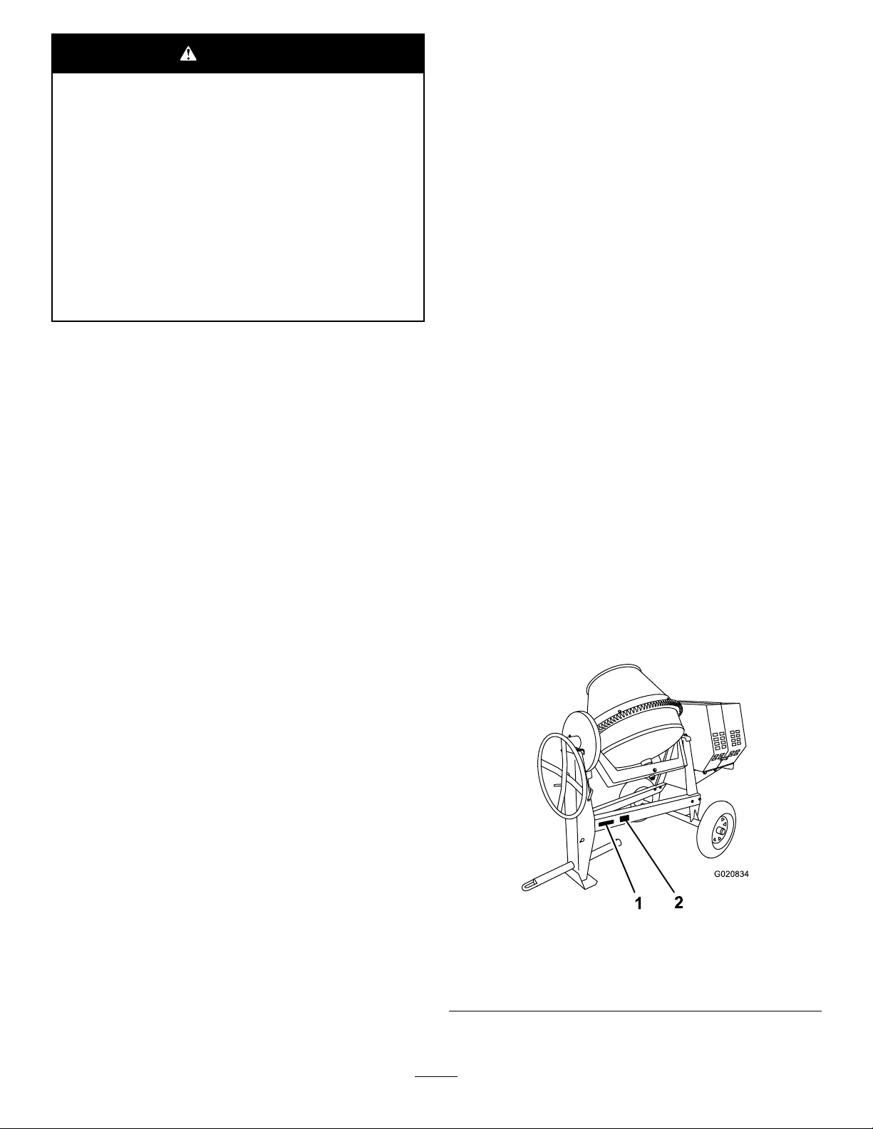
1.Modelandserialnumber
2
Models68004C,68006C,and68009C
location
Figure1
2.Vehicleidentication
number(VIN)location
Contactusatwww.Toro.com.
PrintedintheUSA
AllRightsReserved
Page 3
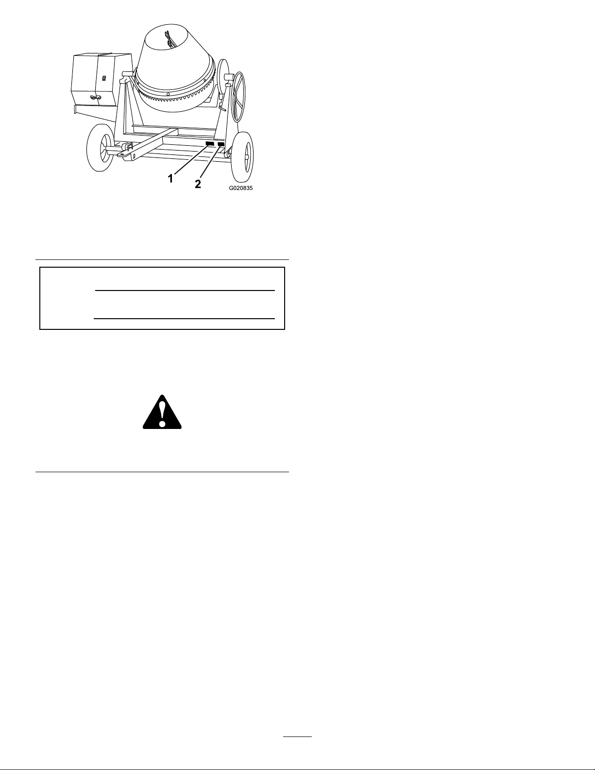
G020835
1
2
Figure2
Models68007Cand68008C
1.Modelandserialnumber
location
ModelNo.
SerialNo.
2.Vehicleidentication
number(VIN)location
Thismanualidentiespotentialhazardsandhassafety
messagesidentiedbythesafetyalertsymbol(Figure3),
whichsignalsahazardthatmaycauseseriousinjuryordeath
ifyoudonotfollowtherecommendedprecautions.
Figure3
1.Safetyalertsymbol
Thismanualuses2wordstohighlightinformation.
Importantcallsattentiontospecialmechanicalinformation
andNoteemphasizesgeneralinformationworthyofspecial
attention.
TireInformation
TheDOTtireinformationislocatedontheside
ofeachtire.Thisinformationgivesloadandspeed
ratings.Replacementtiresshouldhavethesame
orbetterratings.Formoreinformationgoto
http://www.nhtsa.gov/Vehicle+Safety/Tires.
Note:Thevariousmachinesinthismanualhavedifferent
weights;refertoSpecications(page13)toensurethatthe
tiresonyourmachinemeetorexceedtheweightrequirements
ofyourmachine.
Contents
Safety...........................................................................4
SafeOperatingPractices...........................................4
SafetyandInstructionalDecals.................................7
Setup............................................................................9
1InstallingtheTowPole—Models68004C,
68006C,and68009C............................................9
2InstallingtheTongue—Models68007Cand
68008C...............................................................9
3InstallingtheSafetyChain.....................................10
ProductOverview.........................................................11
Controls...............................................................12
Specications........................................................13
Operation....................................................................14
PreparingtoT owtheMachine..................................14
TowingtheMachine...............................................19
PreparingtoUsetheMachine...................................19
LoweringtheStabilizerLegs....................................20
OpeningandClosingtheCowl.................................20
AddingFuel...........................................................21
CheckingtheEngine-oilLevel..................................23
StartingandStoppingtheEngine..............................23
UsingtheMachine..................................................24
MixingtheMaterial.................................................25
UsingtheDrum.....................................................25
Maintenance.................................................................27
RecommendedMaintenanceSchedule(s)......................27
PremaintenanceProcedures........................................27
PreparingtheMachineforMaintenance.....................27
DisconnectingtheSpark-plugWire...........................27
RemovingandInstallingtheDividerPlate..................28
Lubrication...............................................................29
LubricatingtheMachine..........................................29
EngineMaintenance..................................................29
ServicingtheAirCleaner.........................................29
ChangingtheEngineOil.........................................30
ServicingtheSparkPlug..........................................31
ServicingtheSparkArrester.....................................33
FuelSystemMaintenance...........................................34
ServicingtheFuelSystem........................................34
BeltMaintenance......................................................35
ServicingtheDriveBelts.........................................35
CheckingtheDrive-BeltTension..............................35
AdjustingtheDrive-BeltTension..............................35
ReplacingtheDriveBelts.........................................36
ReplacingtheLightBulbs............................................36
ReplacingtheRear-facingSideBulbs.........................36
ReplacingtheSide-facingBulbs................................36
ReplacingtheCenterBulbs......................................37
Cleaning...................................................................37
CleaningtheMachine..............................................37
Storage........................................................................38
StoringtheMachine................................................38
Troubleshooting...........................................................39
3
Page 4

Safety
Improperlyusingormaintainingthemachinecanresult
ininjury.Toreducethepotentialforinjury,complywith
thesesafetyinstructionsandalwayspayattentiontothe
safetyalertsymbol,whichmeans:
or
Danger
complywiththeinstructionmayresultinpersonalinjury
ordeath.
—personalsafetyinstruction.Failureto
SafeOperatingPractices
Thismachineiscapableofamputatinghands.Alwaysfollow
allsafetyinstructionstoavoidseriousinjuryordeath.
WARNING
Machiningorhandlingstone,masonry,concrete,
metal,andothermaterialscangeneratedust,mists,
andfumescontainingchemicals,suchassilica,
knowntocauseseriousorfatalinjuryorillness,
suchasrespiratorydisease,silicosis,cancer,birth
defects,orotherreproductiveharm.
•Controldust,mist,andfumesatthesource
wherepossible.Usewaterfordustsuppression,
whenfeasible.
•Usegoodworkpracticesandfollowthe
recommendationsofthemanufacturer
orsupplier,CCOHS,OSHA,andother
occupationalandtradeassociations.
•Alwaysfollowrespiratoryprecautions.
•Whenthehazardsfrominhalationcannotbe
eliminated,theoperatorandanybystanders
shouldweararespiratorapprovedbyCCOHSor
OSHAforthematerialbeinghandled.
WARNING
Engineexhaustcontainscarbonmonoxide,an
odorless,deadlypoisonthatcankillyou.
Donotruntheengineindoorsorinanenclosed
area.
Training
•ReadtheOperator'sManualandothertrainingmaterial.If
theoperator(s)ormechanic(s)cannotreadorunderstand
theinformation,itistheowner'sresponsibilitytoexplain
thismaterialtothem.
•Becomefamiliarwiththesafeoperationoftheequipment,
operatorcontrols,andsafetysigns.
•Alloperatorsandmechanicsshouldbetrained.The
ownerisresponsiblefortrainingtheusers.
Caution
,
W ar ning
•Neverletchildrenoruntrainedpeopleoperateorservice
theequipment.Localregulationsmayrestricttheageof
theoperator.
•Theowner/usercanpreventandisresponsiblefor
accidentsorinjuriesoccurringtopeopleordamageto
,
property.
Towing
Checkwithyourlocalcountyorstatetowingsafety
regulations,inadditiontomeetingTransportCanada(or
DepartmentofTransportationifintheU.S.)towingsafety
regulations,beforetowingthemachine.
•Inordertoreducethepossibilityofanaccidentwhile
transportingthemachineonpublicroads,makesurethat
thetowingvehicleismechanicallysoundandingood
operatingcondition.
•Shutdowntheenginebeforetransportingthemachine.
•Whentowingwithaballhitch,ensurethattheballhitch
youareusingisthepropersizeforthehitchcoupleron
themachine.
•Whentowingwithapintlehitch,ensurethattheeyeof
thetowpoleisthecorrectdimensionforthepintlehook.
•Inspectthehitchandcouplingforwear.Nevertowthe
machinewithdamagedordefectivehitches,couplings,
chains,orothercomponents.
•Checkthetireairpressureonthetowingvehicleandthe
machine.
•Checkthetiretreadandsidewallfordamageandwear.
•Properlyattachthesafetychainstothetowingvehicle.
•Ensurethatthedirectionalandbrakelightsareworking
properly.
•Ensurethatthedirectional,backup,andbrakelightsof
thetowvehicleareworkingproperly.
•Beforetowing,checktomakecertainyourmachineis
correctlyandsecurelyattachedtothetowingvehicle.
•Ensurethatthesafetychainsareproperlysecuredtothe
vehicle,andleaveenoughslackforturning.
•Donotcarryanymaterialinthemachinewhentowing.
•Avoidsuddenstopsandstarts.Thiscancauseskidding,
orjackkning.Smooth,gradualstartsandstopswill
improvetowing.
•Avoidsharpturnstopreventrolling.Towonlywitha
vehiclethathasahitchdesignedfortowing.Donot
attachtowedequipmentexceptatthehitchpoint.
•Donottowthemachinefasterthan88km/h(55mph).
•Usecautionwhenbackingup;useaspotteroutsidethe
vehicletoguideyou.
•Donotallowanyonetositorrideonthemachine.
•Disconnectthemachinefromthetowvehiclebefore
usingit.
•Placechockblocksunderneaththetirestopreventthem
fromrollingwhilethemachineisparked.
4
Page 5

Preparation
Becomefamiliarwiththesafeoperationoftheequipment,
operatorcontrols,andsafetysigns.
•Useonlyaccessoriesandattachmentsapprovedbythe
manufacturer.
•Wearpersonalprotectiveequipmentandappropriate
clothing,includingthefollowing:
–Hardhat
–Respiratorordustmask
–Faceshieldorsafetyglasses
–Hearingprotection
–Safetyshoes
–Longpants
–Shirtwithlongsleevesbuttonedatthewrists
–Tight-ttinggloveswithoutdrawstringsorloosecuffs
•Securelonghair,looseclothing,orjewelrythatmayget
tangledinmovingparts.
•Operatingtheequipmentsafelyrequiresthefullattention
oftheoperator.Donotwearradioormusicheadphones
whileoperatingthemachine.
•Ensurethatthemachineisonalevelsurfacebefore
operatingthemachine.
•Chockthetiresofthemachinetopreventunintended
movement.
•Beforeeveryuse,dothefollowing:
–Inspectthecoupler,ball,andhitch.
–Ensurethatalllightsarefunctioningproperly(if
equippedwithalightkit).
–Ensurethatthetiresareproperlyinatedas
recommended.
–Ensurethatthelugnutsaretightandtorqued
properly.
–Ensurethatthemachineisproperlysecured.
Operation
•Neverrunanengineinanenclosedorpoorlyventilated
area.
•Onlyoperatethemachineingoodlightingconditions.
•Beforestartingthemachine,makesurethatthereareno
personsorobstaclesnearorunderthemachine.
•Shutofftheenginebeforeleavingthemachineforany
reason.
Neverleavearunningmachineunattended.Alwaysstop
theengineandverifythatallmovingpartshavestopped.
•Chockthetiresofthemachineorkeepitattachedtothe
towingvehiclewhenitisnotinuse,topreventitfrom
rolling.
•Avoidprolongedbreathingofexhaustfumes.Engine
exhaustfumescancausesicknessordeath.
•Keephandsawayfromanymovingparts.Keepfeetaway
fromthetiresandthefrontpost.
•Donotoperatethemachineundertheinuenceof
alcoholordrugs.
•Ensurethattheareaisclearofotherpeopleorpetsbefore
operatingthemachine.Stopthemachineifanyoneenters
thearea.
•Neverplaceyourhandsoranysolidobjectintothedrum
whenthemachineisinoperation.
•Donottouchpartswhichmaybehotfromoperation.
Allowthemtocoolbeforeattemptingtomaintain,adjust,
orservicethemachine.
•Nevermovethemachinewhiletheengineisrunning.
•Keepthecowlclosedandlatchedduringoperation.
•Ensurethatalltheguardsandshieldsaresecurelyinplace
beforeoperatingthemachine.
•Disconnectthespark-plugwireandkeepitawayfromthe
sparkplugtopreventaccidentalstartingwhilemaintaining
themachine.
•Ifthemixingpaddlesstrikeaforeignobjectorifthe
machineshouldstartmakinganunusualnoiseor
vibration,stoptheengineandemptythedrum.Waitfor
allmovingpartstocometoacompletestopandcool.
Vibrationisgenerallyawarningoftrouble.Disconnect
thespark-plugwireandinspectforcloggingordamage.
Cleanandrepairand/orreplacedamagedparts.
•Donotchangetheenginegovernorsettingoroverspeed
theengine.
•Lightningcancausesevereinjuryordeath.Ifyousee
lightningorhearthunderinthearea,donotoperatethe
machine;seekshelter.
MaintenanceandStorage
•Beforeperformingmaintenance,dothefollowing:
–Parkthemachineonlevelground.
–Stoptheengine.Waitforallmovementtostopbefore
adjusting,cleaning,orrepairing.
–Lettheenginecoolbeforeperformingmaintenance
orstoring.
–Removethespark-plugwirebeforemakingany
repairs.
–Disengageallpowerandoperationcontrols.
•Neverlubricate,service,repair,oradjustthemachine
whileitisrunning.
•Keepequipmentmaterialsclearfromthemuferand
enginetohelppreventres.Cleanupanyoilorfuel
spillage.
•Neverallowuntrainedpersonneltoservicethemachine.
•Keephands,feet,andclothingawayfrommovingparts.
Ifpossible,donotmakeadjustmentswiththeengine
running.
5
Page 6

•Keepallpartsingoodworkingconditionandallhardware
tightened.Replaceallwornordamageddecals.
•Removeanybuildupofgrease,oil,ordebrisfromthe
machine.
•Stopandinspectthemachineifaforeignobjectentersthe
drumorcausesanotherobstruction.Makeanynecessary
repairsbeforestartingthemachine.
•Donottamperwithsafetydevices.
•Chockthetireswhenstoringthemachine.
•Keepallnuts,bolts,screws,andhoseclampssecurely
tightened.Keepequipmentingoodcondition.
•UseonlygenuineTororeplacementpartstoensurethat
theoriginalstandardsaremaintained.
6
Page 7
SafetyandInstructionalDecals
Safetydecalsandinstructionsareeasilyvisibletotheoperatorandarelocatednearanyareaofpotential
danger.Replaceanydecalthatisdamagedorlost.
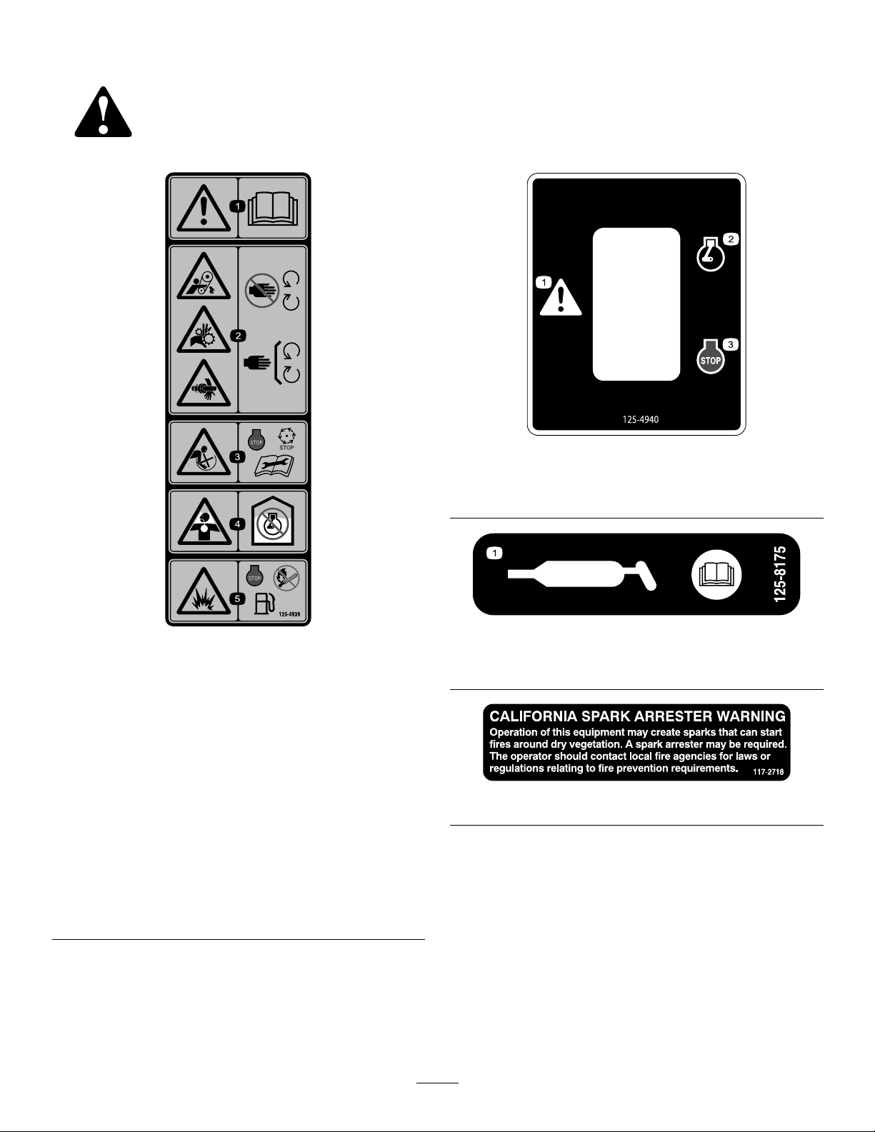
125–4940
1.Warning—readthe
Operator’sManual.
2.Handandarm
entanglementatthe
beltdrive;crushinghazard
ofhand;entanglement
hazardofhandatthe
shaft—keephandsaway
frommovingparts;keep
allguardsandshieldsin
place.
3.Entanglementhazardat
paddles—stoptheengine
andwaitforallmoving
partstostopbefore
performingmaintenance.
1.Warning3.Engine—stop
2.Engine—run
125–4939
4.Toxicgasinhalation
hazard—Don’trunthe
engineinanenclosed
space.
5.Explosionhazard—stop
theengineandkeep
awayfromameswhen
refueling.
1.ReadtheOperator’sManualforinformationongreasing
themachine.
125–8175
117–2718
7
Page 8
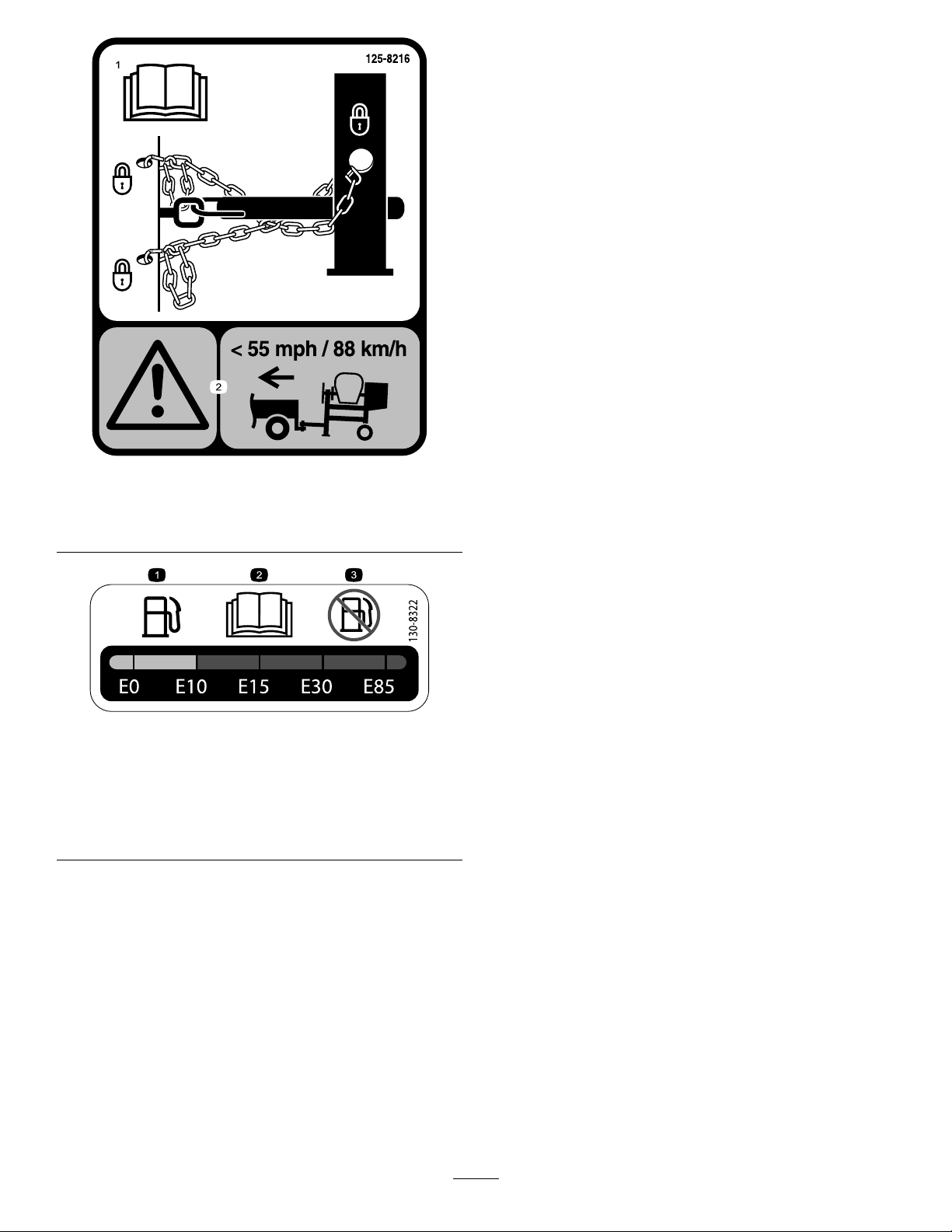
125–8216
1.ReadtheOperator’s
Manualforinformationon
howtotowthemachine.
1.Onlyusefuelwithan
alcoholcontentbyvolume
under10%.
2.ReadtheOperator's
Manualformore
informationonfuel.
2.Warning—limittowing
speedtolessthan55mph
/88km/h.
130-8322
3.Donotusefuelwithan
alcoholcontentbyvolume
greaterthan10%.
8
Page 9
Setup
5
1
2
4
6
3
G019804
G021091
1
Note:Iftheself-lockingnyloninsertinthelocknut
wearswithuse,replacethenutwithanewGrade5or
Grade8locknut.
1
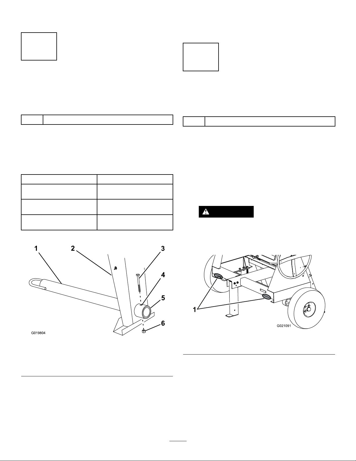
InstallingtheTow Pole—Models68004C,68006C, and68009C
Partsneededforthisprocedure:
1
Towpolekit(soldseparately)
InstallingtheTowPoletotheMachine
Note:Thetowpoleispurchasedseparately.SeeyourToro
authorizeddealerforthetowpoleoptionsforyourmachine.
Themachinehasthefollowingtowpoleoptions:
HitchTypeLength
50mm(2inch)ball—stamped78.7cm(31inches)or127cm
50mm(2inch)ball—forged78.7cm(31inches)or127cm
Pintle
1.Removetheboltandnutfromthetowpole(Figure4).
(50inches)
(50inches)
78.7cm(31inches)or127cm
(50inches)
2
InstallingtheTongue—Models 68007Cand68008C
Partsneededforthisprocedure:
1
Towpolekit(soldseparately)
InstallingtheTonguetotheMachine
Note:Thetowpoleispurchasedseparately.SeeyourToro
authorizeddealerforthetow-poleoptionsforyourmachine.
1.Lowertherearstabilizerlegsforsafety;referto
LoweringtheStabilizerLegs(page20).
2.Placejackstandsunderthefrontframerailtoprevent
themachinefromtippingforward(Figure5).
WARNING
Mechanicalorhydraulicjacksmayfailto
supportthemachineandcauseseriousinjury.
Usejackstandswhensupportingthemachine.
Figure4
1.Towpole4.Bolthole
2.Frontpost
3.Bolt6.Nut
2.Slidethetowpoleforwardandaligntheholeinthe
polewiththeholeintheframetting(Figure4).
3.Inserttheboltthroughtheholesinthettingandthe
pole(Figure4).
4.Threadthenutontotheboltandtightenthemuntil
theyaretightagainsttheframetting(Figure4).
5.Frametting
Figure5
1.Supportpoints
3.Removethe2nutsandboltsthatsecurethefront
stabilizerlegtotheframe(Figure6),andremovethe
frontstabilizerleg.
9
Page 10
G021092
1
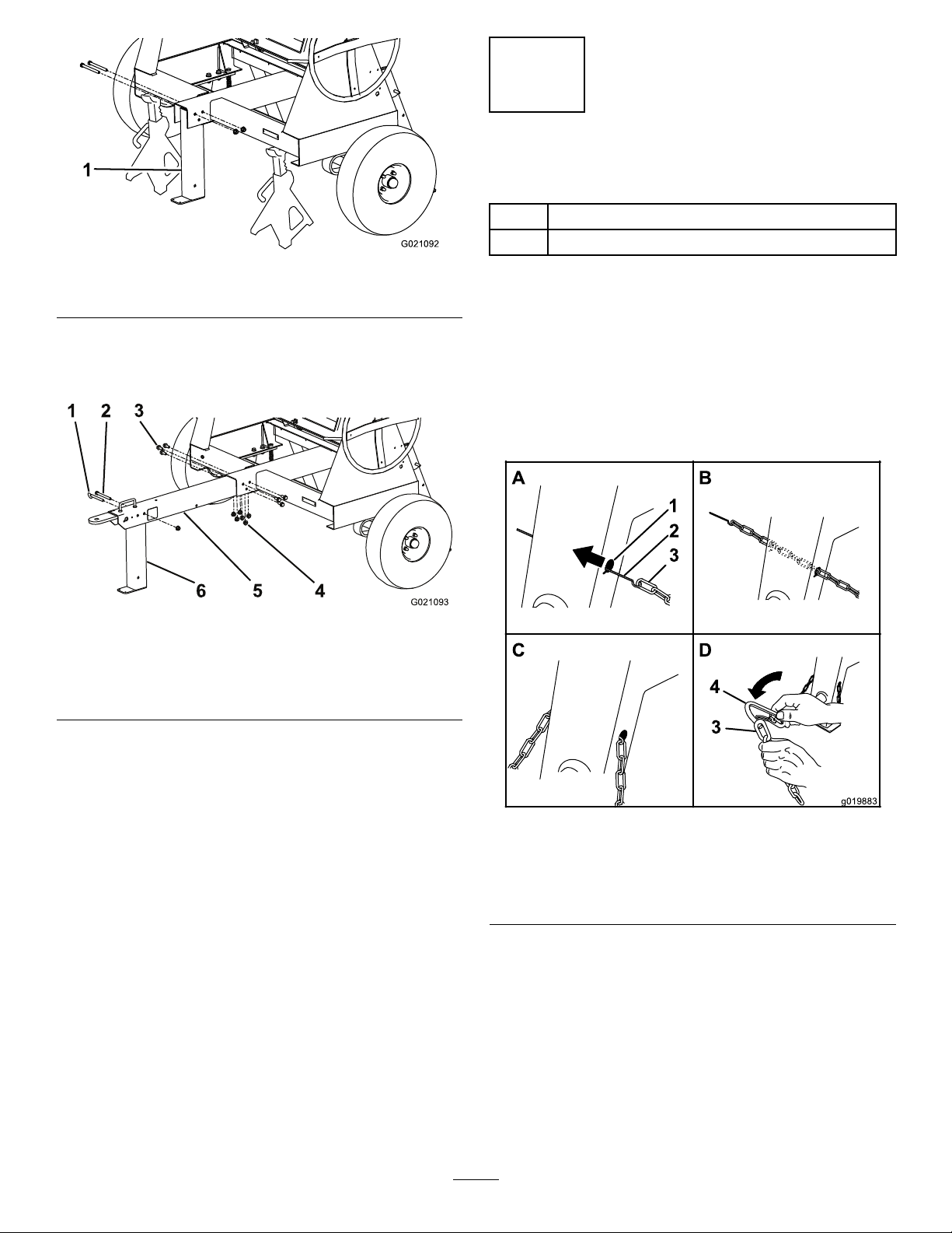
Figure6
1 2
3
4
5
6
G021093
A
B
D
g019883
2
3
4
3
1
3
InstallingtheSafetyChain
Partsneededforthisprocedure:
1
Safetychain(soldwithoptionaltowpolekit)
2
Connectinglink(soldwithoptionaltowpolekit)
1.Frontstabilizerleg
4.Installthetongueintotheopeningatthefrontofthe
machine,andsecureitwith6nutsandshortbolts
torquedto102N-m(75ft-lb);refertoFigure7.
Figure7
1.Clevispin4.Nut(7)
2.Longbolt5.Tongue
3.Shortbolt(6)
6.Frontstabilizerleg
InstallingtheSafetyChaintothe
Machine
Note:Thesafetychainispartoftheoptionaltowpolekit.
1.Formahookontheendofabendablepieceofrodor
stiffwire,(notincluded),andinsertitthroughboth
keyholesinthefrontpostofthemachine(Figure8and
Figure9).
5.Alignthetoprearholeinthefrontstabilizerlegtothe
holepastthehandleinthefrontofthetongue(Figure
7).
6.Installthelongboltthroughtheholes,andsecureit
withanuttorquedto102N-m(75ft-lb);referto
Figure7.
Note:Thestabilizerlegpivotsrearwardonthebolt.
Ifyouinstalltheboltintothewronghole,thestabilizer
legwillnotworkproperly.
7.Inserttheclevispintolockthefrontstabilizerlegin
position(Figure7).
Figure8
Models68004C,68006C,and68009C(Side-dump)
1.Keyhole
2.Rodorwire(notincluded)4.Connectinglink
10
3.Safetychain
Page 11
A
B
D
G019919
2
3
4
3
1
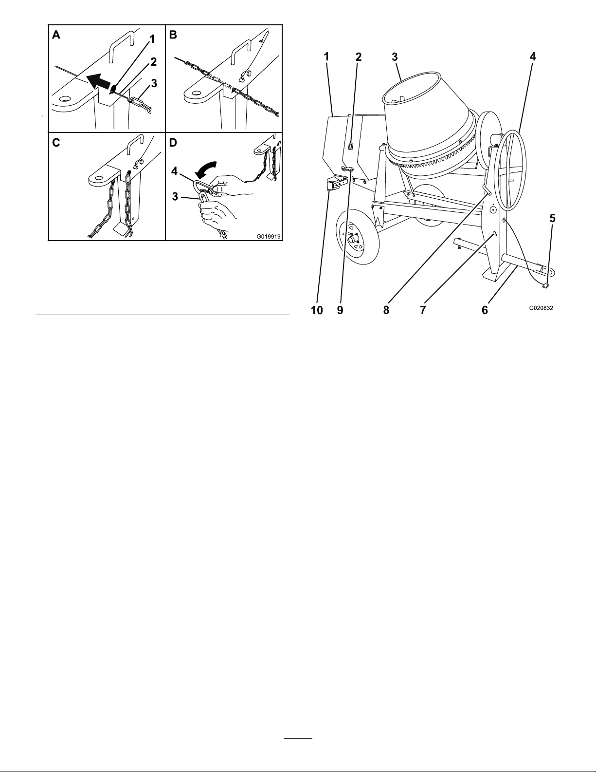
Models68007Cand68008C(End-dump)
G020832
1
2
3
4
5
6
7
8
9
ProductOverview
Figure9
1.Keyhole
2.Rodorwire(notincluded)4.Connectinglink
3.Safetychain
2.Attachthesafetychaintothelengthofrodorwire
(Figure8andFigure9).
3.Pulltherod,orwire,andthesafetychainthroughboth
keyholes(Figure8andFigure9).
Note:Ensurethatapproximatelyequallengthsof
safetychainextendfromeithersideofthefrontpost.
InstallingtheConnectingLinks
Note:Theconnectinglinksarepartoftheoptionaltowpole
kit.
1.Aligntheconnectinglinktothelastlinkinendofthe
safetychain(Figure8andFigure9).
2.Inserttheconnectinglinkthroughthechainlinkuntil
theconnectinglinksnapsclosed(Figure8andFigure
9).
3.Repeatsteps1and2toinstalltheotherconnectinglink
intheotherendofthesafetychain.
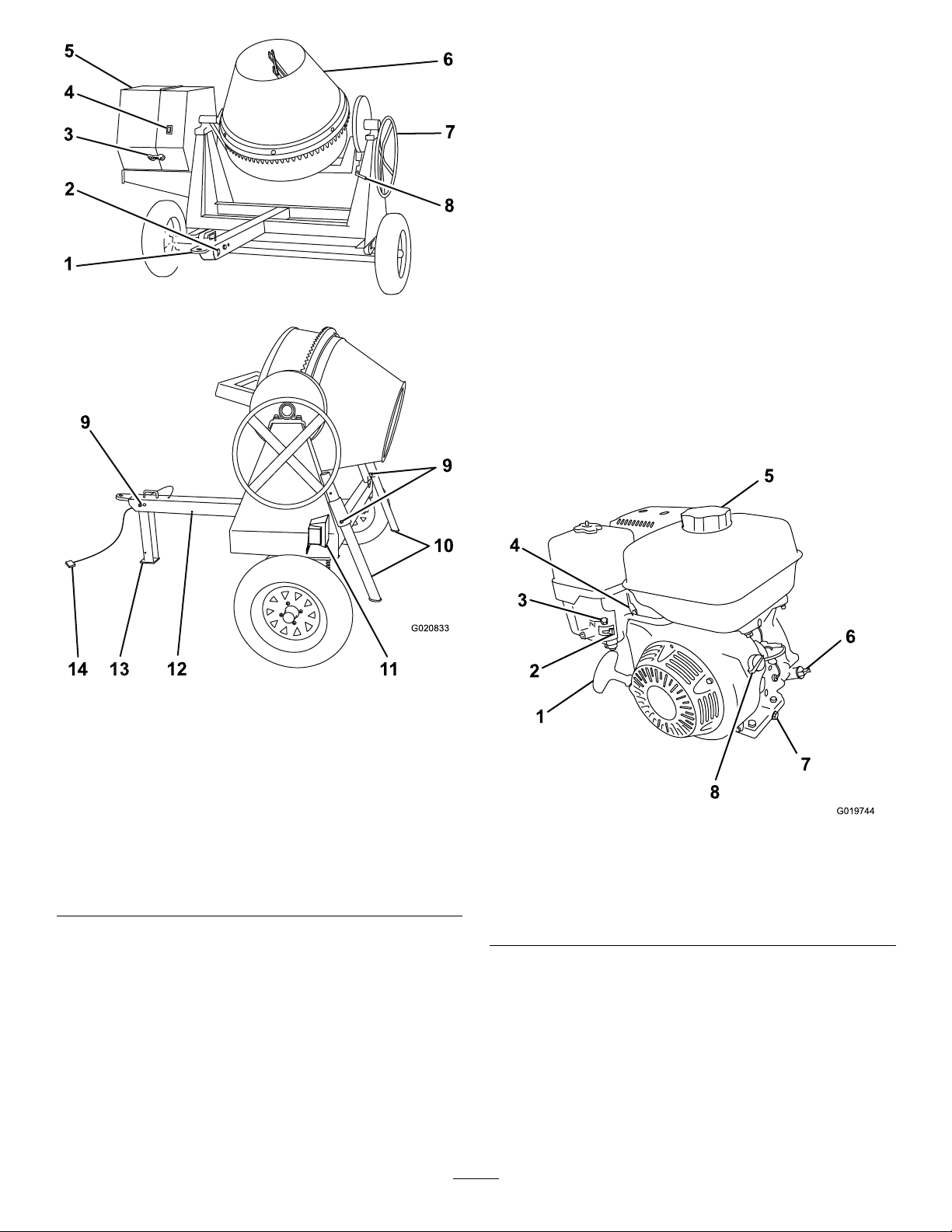
Figure10
Models68004C,68006C,and68009C
1.Enginecowl6.Towpole
2.Engineswitch
3.Drum8.Drum-tiltbrake
4.Handwheel9.Rubberlatch
5.Lightingwiringharness
7.Safety-chainkeyholes
10.Trailerlight(2)
11
Page 12
13
5
4
2
6
7
8
G020833
9
10
11
12
9
14
Controls
1
2
3
5
6
7
8
G019744
Becomefamiliarwithallofthecontrolsbeforeyoustartthe
engineandoperatethemachine.
EngineSwitch
WhentheengineswitchonthecowlisintheRunposition,
itallowstheenginetorun.Movingtheengineswitchtothe
Stoppositionstopstheengine.
Handwheel
Thehandwheelcontrolsthedischargingactionofthedrum.
Drum-tiltBrake
Thedrum-tiltbrakelocksthedrumintoanuprightposition
oradischargingposition.
EngineControls
Figure11
Models68007Cand68008C
1.Tongue-mountedtow
coupler
2.Safety-chainkeyholes9.Clevispin
3.Rubberlatch10.Rearstabilizerlegs
4.Engineswitch
5.Enginecowl12.Rearwardpinhole
6.Drum13.Frontstabilizerleg
7.Handwheel14.Lightingwiringharness
8.Drum-tiltbrake
11.Trailerlight(2)
Figure12
1.Recoil-starthandle5.Fuel-tankcap
2.Fuelvalve6.Dipstick
3.Chokelever7.Oil-drainplug
4.Throttlelever
8.On/Offswitch
FuelValve
Thefuelvalve(Figure13)islocatedunderneaththechoke
lever.MovetheleverforthefuelvalvetotheOnposition
beforeattemptingtostarttheengine.Whenyouhavenished
mixing,stoptheengineandmovethefuel-valvelevertothe
Offposition.
12
Page 13

1
2
3
G018792
Figure13
OFF
ON
1
OFF
ON
G021 103
2
1.Fuel-valvelever3.Throttlelever
2.Chokelever
ChokeLever
speedofthemixingpaddles.Forbestperformance,setthis
controltothefastpositionwhenmixingmaterial.
EngineOn/OffSwitch
TheOn/Offswitch(Figure14)allowstheoperatorofthe
machinetostartandstoptheengine.Thisswitchislocated
onthefrontoftheengine.RotatetheOn/Offswitchtothe
Onpositiontostartandruntheengine.RotatetheOn/Off
switchtotheOffpositiontostoptheengine.
Figure14
1.Offposition2.Onposition
Usethechokelever(Figure13)tostartacoldengine.Before
pullingtherecoil-starthandle,movethechokelevertothe
closedposition.Oncetheengineisrunning,movethechoke
levertotheopenposition.Donotusethechokeiftheengine
isalreadywarmeduportheairtemperatureishigh.
ThrottleLever
Thethrottlelever(Figure13)controlsthespeed(rpm)ofthe
engine.Itislocatednexttothechokelever.Itsetstheengine
speedandthereforecanincreaseanddecreasetherotation
Recoil-startHandle
Tostarttheengine,pulltherecoil-starthandle(Figure12)
quicklytoturntheengineover.Theenginecontrolsdescribed
abovemustallbesetcorrectlyfortheenginetostart.
Oil-levelSwitch
Theoil-levelswitchislocatedinsidetheengine,anditwill
notallowtheenginetoruniftheoillevelisbelowthesafe
operatinglimit.
Specications
Note:Specicationsanddesignaresubjecttochangewithoutnotice.
Model
BatchCapacity
TotalV olume0.255cubicmeters
DrumMaterial
Length198cm
Width1 17cm
Height147cm
Weight313kg
68004C68006C68007C68008C68009C
0.17cubicmeters
(6.0cubicfeet)
(9.0cubicfeet)
SteelSteelSteel
(78inches)
(46inches)
(58inches)
(690lb)
0.255cubicmeters
(9.0cubicfeet)
0.43cubicmeters
(15.1cubicfeet)
213cm
(84inches)
142cm
(56inches)
165cm
(65inches)
362.9kg
(800lb)
0.255cubicmeters
(9.0cubicfeet)
0.43cubicmeters
(15.1cubicfeet)
216cm
(85inches)
216cm
(85inches)
180cm
(71inches)
397kg
(875lb)
0.255cubicmeters
(9.0cubicfeet)
0.43cubicmeters
(15.1cubicfeet)
PolyethylenePolyethylene
216cm
(85inches)
216cm
(85inches)
180cm
(71inches)
397kg
(875lb)
0.255cubicmeters
(9.0cubicfeet)
0.43cubicmeters
(15.1cubicfeet)
213cm
(84inches)
142cm
(56inches)
165cm
(65inches)
381kg
(837lb)
13
Page 14
Operation
G019806
1
2
3
1
2
G019733
Important:Beforeoperating,checkthefuelandoil
levels,andremovedebrisfromthemachine.Ensurethat
theareaisclearofpeople.
PreparingtoTowtheMachine
Important:Ensurethatyourtowvehiclehastowing
capacityfortheweightofthemachine.
Important:UseaClass2orlargerreceiver.
Note:Ensurethatyourtowvehiclehastheappropriatehitch
totowthemachine;optionsincludea50mm(2inch)ball
hitchorapintlehitch.
Note:Ensurethattheelectricalconnectorofthetowvehicle
iscompatiblewiththeelectricalconnectorofthemachine.
Themachineusesastandard4-atplug.Ifyourtowvehicle
hasadifferenttypeofplug,obtainanadapterfroman
automotivepartsstore.
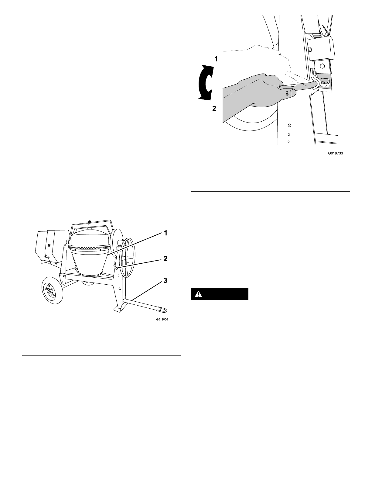
1.Ensurethattheengineisstopped,thefuelvalveisoff,
andthedrumisempty.
2.Usingthehandwheel,positionthedrumsothatitis
pointingdowntowardtheground(Figure15).
Figure16
Drum-tiltBrake
1.Unlockedposition2.Lockedposition
4.Ensurethattheenginecowlisclosedandlatched;refer
toClosingtheCowl(page21).
5.Inspectthetiresandwheels;refertoCheckingthe
TiresandWheels(page14).
Figure15
1.Drumpointingdown3.Towpoleboltedinplace
2.Drum-tiltbrakeengaged
3.Lockthedrumintopositionbypushingdownonthe
drum-tiltbrakehandle(Figure16).
CheckingtheTiresandWheels
ServiceInterval:Beforeeachuseordaily—Inspectthetires
andwheels.
Aftereachuse—Torquethelugnutsto108to122
N-m(80to90ft-lb)aftertowing.
WARNING
Failuretomaintaincorrecttirepressuremayresult
intirefailureandlossofcontrol,resultingin
propertydamageandseriousinjuryordeath.
•Checkthetirepressurefrequentlytoensure
properination.Ifthetiresarenotinatedto
thecorrectpressure,theywillwearprematurely.
•Inspectthetireconditionbeforetowingand
afteranyoperatingaccident.
TheDOTtireinformationislocatedontheside
ofeachtire.Thisinformationgivesloadandspeed
ratings.Replacementtiresshouldhavethesame
orbetterratings.Formoreinformationgoto
http://www.nhtsa.gov/Vehicle+Safety/Tires.
Note:Thevariousmachinesinthismanualhavedifferent
weights;refertoSpecications(page13)toensurethatthe
tiresonyourmachinemeetorexceedtheweightrequirements
ofyourmachine.
14
Page 15

1.Visuallyinspectthetiresfordamageandwear(Figure
G020836
1
2
3
4
G021 107
G019917
17andFigure18)
Figure17
1.Exampleoftirewearcausedbyunderination
Figure19
RaisingtheStabilizerLegs(Models
68007Cand68008C)
Models68007Cand68008Chaveafrontstabilizerlegand2
rearstabilizerlegs.
Raisethestabilizerlegsbeforetowingthemachine.
1.Adjustthemachinesothatthereisnoweightresting
ontherearstabilizerlegs.
Figure18
1.Exampleoftirewearcausedbyoverination
2.Ensurethatthetiresareinatedtothecorrectair
pressure.ThefollowingTireAirPressuretableshows
theappropriateairpressureforthetiresasinstalledat
thefactory.
Important:Alwayschecktheinformation
ontheactualtiresforthecorrectairpressure
requirement.
Important:Themostcommoncauseoftire
troubleisunderination.Maintainfullair
pressure.
TireAirPressure
ModelTirepressure
68004CMax414kPa(60psi)
68006C,68007C,68008C,
68009C
Max241kPa(35psi)
2.Pulltheclevispinoutoftherearstabilizerlegandthe
bracket(Figure20).
Figure20
3.Ensurethatthewheellugnutsaretorquedto108to
122N-m(80to90ft-lb).Checkthetorqueofthe
wheellugnutsinitiallyandaftertowing.
Note:Torquethelugnutsinthesequenceshownin
Figure19.
3.Slidethestabilizerlegupinthebracket,andalign
thepinholeofthebracketwiththelowerholeinthe
stabilizerleg(Figure20).
4.Pushtheclevispinthroughtheholeinthebracketand
thestabilizerleg(Figure20).
5.Repeatsteps1through4fortheotherrearstabilizer
leg.
6.Liftupwardonthetonguesothatthereisnoweight
restingonthefrontstabilizerleg.
15
Page 16

7.Pulltheclevispinoutfromthefrontstabilizerlegand
G019915
3
2
1
A
B
C
G020359
2
1
thetongue(Figure21).
Figure21
1.Removetheclevispin.3.Installtheclevispin.
2.Rotatethestabilizerleg
up.
8.Rotatethefrontstabilizerlegupintothetongue
(Figure21).
9.Pushtheclevispinthroughtherearwardholeinthe
tongueandthefrontstabilizerleg(Figure21).
UsingtheTowPole
Note:Thetowpoleispurchasedseparatelyandincludesthe
nutandboltneededforinstallation.SeeyourToroauthorized
dealerforthetow-poleoptionsforyourmachine.
HitchingaMachinewithaStampedBallCoupler
(optionalkit)
1.Applychassisgreasetothesocketofthecouplerand
theareaoftheclampthatcontactstheball.
2.Oilthepivotpointsandslidingsurfacesofthecoupler
withSAE30motoroil.
3.Openthecouplerlatch(Figure22).
Figure22
1.Bail
2.Safetypin
4.Positionthecouplerontopofthehitchball(Figure22).
5.Closethecouplerlatch(Figure22).
6.Openthebailonthesafetypin,andinsertthepin
throughtheholeinthelatch(Figure22).
7.Rotatethefreeendofthebailovertheendofthesafety
pinthatisprotrudingthroughthelatch(Figure22).
8.Connectthewireplugofthetowvehicletothewire
plugofthemachine.
HitchingaMachinewithaForgedBallCoupler(optional
kit)
1.Applyremovablethread-lockingcompoundtothe
threadsofthecouplerbolttopreventthecoupler
handlefromcomingloose(Figure23).
Important:Applythread-lockingcompoundas
neededinthefuture.
16
Page 17

A
B
D
G019807
5
1
2
3
4
Figure23
G019809
1.Couplerhandle
2.Coupler
3.Clamp
4.Bolt
5.Hitchball
2.Applychassisgreasetothesocketofthecouplerand
theareaoftheclampthatcontactstheball.
3.Pushthecouplerboltupthroughthecouplerclamp
andthecouplertop,andconnectthecouplerhandleto
thebolt(Figure23).
4.Positionthecouplersothatthesocketisontopofthe
hitchballandtheclampisundertheball.
5.Turnthecouplerhandleclockwisetothreaditontothe
boltuntilitissecure(Figure23).
Note:Useawrenchtokeeptheboltfromspinning.
6.Connectthewireplugofthetowvehicletothewire
plugofthemachine.
HitchingaMachinewithaPintleHitchCoupler(optional
kit)
1.Removethepinfromthepintlehitchandopenit
(Figure24).
Figure24
2.Positiontheringonthetowpoleontothehookofthe
pintlehitch(Figure24).
3.Closethetopofthepintlehitchandsecureitwiththe
pin(Figure24).
4.Connectthewireplugofthetowvehicletothewire
plugofthemachine.
17
Page 18

HitchingaMachinewithaPinHitchCoupler(optional
A
B
D
G020084
1
2
3
4
1
2
3
G021 177
1
2
3
4
G019928
kit)
1.Positionthefrontofthepinhitchcouplersothatit
islocatedbetweenthetopandbottomplatesofthe
pin/clevishitchofthetowvehicle,andensurethatthe
holesarealigned(Figure25).
ConnectingtheSafetyChainstothe
TowVehicle
1.Pullthesafetychainthroughtheslotsinthekeyholes,
sothatthelengthsoneachsideareequal.
2.Crossbothlengthsofchainunderthetowpole(under
thetongueforend-dumpmodels68007Cand68008C).
Formodels68004C,68006C,and68009Creferto
Figure26.Formodels68007Cand68008Creferto
Figure27.
Note:Crossingthechainsdecreasesthechancesof
thefrontofthemachinedroppingtothegroundifthe
hitchdoesnotholdtheconnection.
Figure25
1.Hitchpin3.Pin-hitchcoupler
2.Hairpincotter
4.Pin/clevis-hitchreceiver
2.Inserta19mm(3/4inch)or22mm(7/8inch)hitch
pinthroughtheholesinthecouplerandthereceiver
hitch(Figure25).
3.Insertahairpincotterthroughtheholeinthebottom
ofthehitchpin(Figure25).
4.Connectthewireplugofthetowvehicletothewire
plugofthemachine.
Figure26
Models68004C,68006C,and68009C
1.Connectinglinks3.Chaincrossedundertow
2.Keyholesinfrontpost
Figure27
Models68007Cand68008C
1.Connectinglinks3.Chaincrossedunder
2.Keyholes
pole
tongue
4.Chain
3.Connecteachlengthofchaintothesafetychain
mountingpointonthetowvehiclewiththeconnecting
links(Figure28).
18
Page 19

Important:Ensurethatthechainhasenough
G020365
1
2
3
4
G020828
slackforturningaroundcornerswhentowingthe
machine.
Note:Formodels68004C,68006C,and68009C,
stowtheexcesschaininsidethebottomofthefront
postbypushingitintothekeyholesandlatchingthe
appropriatelinksintothekeyholeslots.
Note:Formodels68007Cand68008C,connectthe
connectinglinkstotheappropriatelinksinthesafety
chain(Figure28).Iftheexcesschainhangstoolowand
touchestheground,connectitagaintotheconnecting
linktoraiseitawayfromtheground.
CheckingtheLights
•Ensurethatthetaillightsofthemachineilluminatewhen
youturnontheheadlightsoftowvehicle.
•Ensurethatthebrakelightsofthemachineilluminate
whenyoupressthebrakepedalofthetowvehicle.
•Ensurethattheappropriateturnsignalasheswhenyou
operatethecorrespondingturnsignalofthetowvehicle.
TowingtheMachine
WARNING
Towingthemachineathighspeedincreasesthe
riskofahitchmalfunctionandtirefailure.Higher
speedsalsoincreasethemomentumofthemachine
andbrakingdistance.Ifthemachinebecomes
detachedfromthetowvehicleathighspeed,it
couldcausedamagetoproperty,orinjuryordeath
tobystanders.
Donotexceed88km/h(55mph)whentowingthe
machine.Forpoorroadconditionsorinclement
weather,reducespeedaccordingly.
WARNING
Figure28
1.Connectinglink3.Chainlink
2.Safetychainmounting
pointontowvehicle
4.Chain
Towingthemachinewithmaterialinthedrum
increasestheriskofahitchmalfunctionandtire
failure.Inaddition,materialcouldbounceoutof
thedrumandhitothervehiclesand/orpeople.
Materialinthedrumincreasestheweight,which
affectsmomentumandbrakingdistance.
Donottowthemachinewithmaterialinthedrum.
ConnectingtheLightingWireHarness
Connecttheelectricalplugofthemachinewiththeelectrical
plugofthetowvehicleasshowninFigure29.
•ReviewandunderstandSafeOperatingPractices(page4).
•Testthebrakesofthetowvehiclebeforetowing.
•Avoidsuddenstartsandstopswhiletowingthemachine.
PreparingtoUsetheMachine
•Reviewallofthesafetydecalsonthemachine.
Figure29
Note:Themachineusesastandard4-atplug.Ifyourtow
vehiclehasadifferenttypeofplug,obtainanadapterfroman
automotivepartsstore.
Important:Routinelycheckthelightstoensurethat
theyareworkingproperly,includingthetaillights,brake
lights,andeachappropriateturnsignal.
•Useahard-hat,hearingprotection,ashirtwithlong
sleevesbuttonedatthewrists,tight-ttinggloveswithout
drawstringsorloosecuffs,eyeprotection,andadust
maskorrespirator.Ameshvisoralonedoesnotprovide
sufcienteyeprotection;supplementwithprotective
glasses.
•Ensurethatyouarefamiliarwithsafetyregulationsand
shutdownproceduresdescribedinthisOperator’sManual
andtheengineowner’ smanual.
•Ensurethatallguardsareinplaceandingoodcondition.
•Ensurethatthepaddlesareinplaceandingood
condition.
19
Page 20

•Formodels68007Cand68008C,lowerthefrontandrear
G019918
G019916
1
2
3
stabilizerlegs.
•Checkthefuelandoillevelsoftheengine.
•Whenpreparingtomixmaterial:
1.Movethemachinetoaleveljob-sitesurface.
2.Removethemachinefromthetowvehicle.
3.Chockthefrontandbackofthetirestoprevent
themachinefrommoving.
4.Ensurethatthedrumisinthemixposition
(upright).
5.Ensurethatthedrumlatchisengagedandthatthe
drumdoesnotrotatetowardthedumpposition.
LoweringtheStabilizerLegs
6.Pulltheclevispinoutfromthefrontstabilizerlegand
thetongue(Figure31).
Models68007Cand68008Conly
Models68007Cand68008Chaveafrontstabilizerlegand2
rearstabilizerlegstokeepthemachinefromtippingforward
orbackwardduringoperation.Movethestabilizerlegsinto
theloweredpositionbeforeoperatingthemachine.
1.Pulltheclevispinoutfromtherearstabilizerlegand
thebracket(Figure30).
Figure31
1.Removetheclevispin.3.Installtheclevispin.
2.Rotatethestabilizerleg
down.
7.Rotatethefrontstabilizerlegdowntowardtheground
(Figure31).
8.Pushtheclevispinthroughthefrontholeinthetongue
andthefrontstabilizerleg(Figure31),andcarefully
lowerthemachinetotheground.
OpeningandClosingtheCowl
OpeningtheCowl
1.Atthesideofthemachinewherethefrontcowland
rearcowlmeet,grasptheringofthelatchandpullit
offfromthelatchanchorontherearcowl(Figure32).
Figure30
2.Slidethestabilizerlegdowninthebracketandalign
thepinholeofthebracketwiththeupperholeinthe
stabilizerleg(Figure30).
3.Pushtheclevispinthroughtheholeinthebracketand
thestabilizerleg(Figure30).
4.Repeatsteps1through3fortheotherrearstabilizer
leg.
5.Liftupwardonthetonguetoprovideclearanceforthe
frontstabilizerleg.
20
Page 21

A
B
D
1
G019879
2
3
4
1
AddingFuel
••Forbestresults,useonlyclean,fresh(lessthan30days
old),unleadedgasolinewithanoctaneratingof87or
higher((R+M)/2ratingmethod).
•ETHANOL:Gasolinewithupto10%ethanol(gasohol)
or15%MTBE(methyltertiarybutylether)byvolume
isacceptable.EthanolandMTBEarenotthesame.
Gasolinewith15%ethanol(E15)byvolumeisnot
approvedforuse.Neverusegasolinethatcontainsmore
than10%ethanolbyvolume,suchasE15(contains15%
ethanol),E20(contains20%ethanol),orE85(contains
upto85%ethanol).Usingunapprovedgasolinemay
causeperformanceproblemsand/orenginedamage
whichmaynotbecoveredunderwarranty.
•Donotusegasolinecontainingmethanol.
•Donotstorefueleitherinthefueltankorfuelcontainers
overthewinterunlessafuelstabilizerisused.
•Donotaddoiltogasoline.
DANGER
Figure32
1.Latch3.Receiver
2.Latchanchor
2.Repeatstep1ontheoppositesideofthemachine.
3.Atthebackofthemachinewheretherearcowlmeets
theframeofthemachine,grasptheringofthelatch
andpullitofffromthelatchanchoronthecowl
(Figure32).
4.Rotatetherearcowlupandforwarduntilitisfully
positionedontopofthefrontcowl(Figure32).
4.V-tting
ClosingtheCowl
1.Rotatetherearcowlrearwardanddownuntilthe
receiveratthebottomcenterofthecowlisalignedwith
theV -ttingandushontheframeofthemachine
(Figure32).
2.Atthebackofthemachine,grasptheringofthelatch
andpullitontothelatchanchorontherearcowl.
3.Atthesideofthemachine,grasptheringofthelatch
andpullitontothelatchanchorontherearcowl.
Incertainconditions,fuelisextremelyammable
andhighlyexplosive.Areorexplosionfromfuel
canburnyouandothersandcandamageproperty.
•Fillthefueltankoutdoors,inanopenarea,when
theengineiscold.Wipeupanyfuelthatspills.
•Neverllthefueltankinsideanenclosedtrailer.
•Donotllthefueltankcompletelyfull.Add
fueltothefueltankuntilthelevelisnohigher
thanthescreenonthelterinthefueltank.
Thisemptyspaceinthetankallowsthefuelto
expand.
•Neversmokewhenhandlingfuel,andstayaway
fromanopenameorwherefuelfumesmaybe
ignitedbyaspark.
•Storefuelinanapprovedcontainerandkeepit
outofthereachofchildren.Donotbuymore
thana30-daysupplyoffuel.
•Donotoperatewithouttheentireexhaust
systeminplaceandinproperworkingcondition.
4.Repeatstep3ontheoppositesideofthemachine
(Figure32).
21
Page 22

DANGER
1
G019799
Incertainconditionsduringfueling,static
electricitycanbereleasedcausingasparkwhich
canignitethefuelvapors.Areorexplosionfrom
fuelcanburnyouandothersandcandamage
property.
•Alwaysplacefuelcontainersonthegroundaway
fromyourvehiclebeforelling.
Addthecorrectamountoffuelstabilizer/conditionertothe
fuel,andfollowthedirectionsofthemanufacturer.
Note:Fuelstabilizer/conditionerismosteffectivewhen
mixedwithfreshfuel.Tominimizethechanceofvarnish
depositsinthefuelsystem,usefuelstabilizeratalltimes.
FillingtheFuelTank
Capacity:5.3L(1.4USgallons)
•Donotllfuelcontainersinsideavehicleoron
atruckortrailerbedbecauseinteriorcarpets
orplastictruckbedlinersmayinsulatethe
containerandslowthelossofanystaticcharge.
•Whenpractical,removefuel-poweredequipment
fromthetruckortrailerandfueltheequipment
withthewheelsontheground.
•Ifthisisnotpossible,thenrefuelsuchequipment
onatruckortrailerfromaportablecontainer,
ratherthanfromafueldispensernozzle.
•Ifafueldispensernozzlemustbeused,keepthe
nozzleincontactwiththerimofthefueltank
orcontaineropeningatalltimesuntilfuelingis
complete.
WARNING
Fuelisharmfulorfatalifswallowed.Long-term
exposuretovaporscancauseseriousinjuryand
illness.
1.Parkthemachineonalevelsurface,stoptheengine,
andallowtheenginetocool.
2.Cleanaroundthefuel-tankcap,andremoveit(Figure
33).
•Avoidprolongedbreathingofvapors.
•Keepyourfaceawayfromthenozzleandthe
fueltankorconditioneropening.
•Keepfuelawayfromyoureyesandskin.
Important:Donotmixoilwithfuel.
RecommendedFuel
UnleadedGasoline
U.S.
Except
U.S.
Pumpoctanerating87orhigher
Researchoctanerating92orhigher
Pumpoctanerating87orhigher
UsingFuelStabilizer/Conditioner
Useafuelstabilizer/conditionerinthemachinetokeepthe
fuelfreshduringstorageof90daysorless.Ifyouarestoring
themachineforlonger,drainthefueltank;refertoStoring
theMachine(page38).
Important:Donotusefueladditivescontaining
methanolorethanol.
Figure33
1.Fuel-tankcap
3.Addunleadedgasolinetothefueltank,untilthelevel
isatthebottomofthemaximumfuellevel,asshown
inFigure34.
Important:Thisspaceinthetankallowsthefuel
toexpand.Donotllthefueltankcompletelyfull.
22
Page 23

G020679
1
g013375
0 20 40 60 80 100 F
-20 -10 0 10 20 30 40 C
o
o
30
5W - 30 / 10W - 30
Figure35
1.Placethemachineonaat,levelsurface,andstopthe
engine.
2.Allowtheenginetocool.
3.Cleanaroundthedipstick.
4.Removethedipstickandwipetheendclean(Figure36).
Figure36
Figure34
1.Maximumfuellevel
4.Installthefuel-tankcapsecurely(Figure33).
5.Wipeupanyfuelthatmayhavespilled.
CheckingtheEngine-oilLevel
ServiceInterval:Beforeeachuseordaily
Important:Use4-cycleengineoilthatmeetsorexceeds
therequirementsforAPIservicecategory
equivalent).
CrankcaseCapacity:1.1L(1.2USqt)
Important:Iftheoillevelinthecrankcaseistoolow
ortoohighandyouruntheengine,youmaydamage
theengine.Thistypeofdamageisnotcoveredbythe
warranty.
Note:UseSAE10W-30forgeneraluse.Youcanuse
theotherviscositiesshowninthechartwhentheaverage
temperatureinyourareaiswithintheindicatedrange(Figure
35).
SJ or later
1.Fillport
2.Dipstick
5.Slidethedipstickfullyintothellportwithout
threadingitintotheport(Figure36).
6.Removethedipstickandlookattheend.Iftheengine
oillevelislow ,slowlypouronlyenoughoilintothell
porttoraisetheleveltotheFullmarkonthedipstick
(Figure36).
Note:ToroPremiumEngineOilisavailablefrom
yourAuthorizedToroDealer.
7.Replaceandsecurethedipstick(Figure36).
(or
3.Oil-levelupperlimit
4.Oil-levellowerlimit
StartingandStoppingthe Engine
StartingtheEngine
1.Ontheenginecowl,movetheengineswitchtotheOn
position(Figure37).
23
Page 24

G019821
1
Figure37
G019815
1
2
3
G019747
1.Engineswitch
2.Ontheengine,movethethrottleleverawayfromthe
Minposition,1/3ofthewaytowardtheMaxposition
(Figure38);refertoThrottleLever(page13).
6.Pulltherecoil-starthandlelightlyuntilyoufeel
resistance,thenpullthehandlebriskly.Returnthe
starterhandlegently(Figure39).
Figure39
Note:IfthechokeleverissettotheClosedpositiontostart
theengine,graduallymoveitbacktowardtheOpenposition
astheenginewarmsup.Iftheenginestallsorhesitates,move
thechokeleverbacktowardtheClosedpositionuntilthe
enginerunssmooth.Allowtheenginetowarmup,then
movethechokelevertotheOpenposition;refertoChoke
Lever(page13).
Figure38
1.Chokelever
2.Fuelvalve
3.MovetheleverofthefuelvalvetotheOnposition—all
thewaytotheright(Figure38);refertoFuelValve
(page12).
4.Positionthechokeleverasfollows:
•Tostartacoldengine,movethechokelevertothe
Closedposition—allthewaytotheleft(Figure38);
refertoChokeLever(page13).
•Tostartawarmengine,movethechokeleverin
theOpenposition—allthewaytotheright.
5.RotatetheengineOn/OffswitchtotheOnposition;
refertoEngineOn/OffSwitch(page13).
3.Throttlelever
StoppingtheEngine
1.Movethethrottlelevertotheslow(turtle)position
(Figure38).
2.Turnthecowl-mountedengineswitchoff(Figure37).
3.MovethefuelvalvetotheOffposition(Figure38)and
rotatetheengineOn/OffswitchtotheOffposition;
refertoEngineOn/OffSwitch(page13).
Important:Ifyouneedtostoptheengineimmediately,
usetheengineswitchlocatedontheoutsideofthe
enginecowl(Figure37).
UsingtheMachine
DANGER
Thismachineiscapableofamputatinghands.
•Stayintheoperatingpositionwhilethemachine
isrunning.
•Keepallbystandersasafedistancefromthe
machine.
•Stopthemachineimmediatelyifanypeopleor
animalsentertheworkarea.
•Neverplaceanypartofyourbodyintoaposition
thatcausesanunsafeoperatingcondition.
24
Page 25

1.Ensurethatthemachineisonlevelgroundandthe
surroundingareaisclearofobstacles.Disconnectthe
machinefromthetowvehicleandchockthefrontand
backofbothtirestopreventanymovement.
2.ReadalltherecommendationsfromtheSafetysection;
refertoSafeOperatingPractices(page4)beforeusing
themachine.
3.Starttheengineandclosetheenginecowl.Allow
theenginetowarmupatidlefor2minutes;referto
StartingtheEngine(page23).
4.Usethehandwheeltomovethedrumintoanupright,
slightlytiltedpositiontoallowaccessforpouring
materialsintothedrum.Thispositionalsoallowsthe
mixingpaddlestomixthematerialsmoreeffectively.
5.Pushthedrum-tiltbrakedowntolockthedruminto
positionandavoidaccidentallydumpingthematerial.
onmoisturecontentofthesandandgravel.Themixshould
haveathicknesssimilartothatofpeanutbutter.
Keepthepouredconcretedampforseveraldaystoobtain
propercuring.Evaporationresultsinweakerconcrete.
Concretecuresthroughhydration,areactionbetweenwater
andcement.
MixingPre-mixConcrete
1.Ensurethatthetiltbrakeisfullyengagedandthatthe
drumisoperatingatfullspeed.
2.Pourwaterintothedrum.
3.Addtherequiredamountofdrypre-mix.
4.Allowthedrumtoturnwhilethemixreachesthe
appropriateconsistency .
Important:Ifyouneedtostopthemachine,usethe
engineswitchlocatedonthecowl;refertoStoppingthe
Engine(page24).
MixingtheMaterial
DANGER
Eyeandskincontactwithconcretematerialsand
breathingthedustinvolvedishazardoustoyour
health.
•Ensurethatthereisadequateairventilation.
•Wearadustmasktopreventinhalationofdust
whileusingthemachine;refertoSafeOperating
Practices(page4).
•Avoiddirectcontactofcementandconcrete
materialswithskinandeyes.
Important:Donotaddmorematerialthanthebatch
capacityforyourspecicmachinemodel;referto
Specications(page13).
Note:Followthemanufacturer’sinstructionsthatareprinted
onthepackagingoftheproductthatyouareusing.
MixingSand,Gravel,andCement
Thetypicalratioformixingconcreteis1partPortland
cement,2partssand,and3partsgravel.
1.Ensurethatthetiltbrakeisfullyengagedandthatthe
drumisoperatingatfullspeed.
2.Pourwaterintothedrum.
3.Addtherequiredamountofgravel.
4.AddtherequiredamountofPortlandcement.
5.Addtherequiredamountofsand.
6.Allowthedrumtoturnwhilethemixreachesthe
appropriateconsistency .
Note:Addingwaterandgravelbeforecementandsand
allowsthemixleftinthedrumfromthepreviousbatchtobe
tumbledoffofthedrumandpaddlesandintothenextbatch.
UsingtheDrum
DANGER
Contactwiththemixingpaddlescouldcause
damageorinjury.
Concretehasthefollowing4basicingredients:
•Sand
•Gravel
•Portlandcement
•Water
Dependingontheapplication,differentratiosofthese4
ingredientscanbeused.
Therearemanyvariationsofconcretemixrecipes,depending
ontheapplication.Itisimportanttousetheappropriate
quantityofwater.Usingtoolittlewaterwillresultindryareas
inthemix,butusingtoomuchwaterwillresultinweaker
concrete.Theamountofwaterneededwillvarydepending
Neverputyourhandsinsidethedrumwhilethe
engineisrunning.
DumpingtheDrum
Note:Whendumpingabatchofmaterial,leavetheengine
runningsothattherotatingdrumhelpsdumpthematerial.
1.Alignawheelbarroworsimilarcontainerofadequate
capacityinthepathofthedrumopening.
2.Whilethedrumisturning,rmlygraspthehandwheel
withonehand.
3.Usingyourotherhand,pullupwardonthedrum-tilt
brakehandletoreleasethebrake.
25
Page 26

4.Use2handstoslowlyturnthehandwheel,allowing
thedrumtotiltinthedesireddirectionanddumpthe
desiredamountofmaterial.
5.Turnthehandwheelintheoppositedirectiontoreturn
thedrumintoanuprightposition.
6.Pushdownonthedrum-tiltbraketolockthedrum
intoposition,avoidingaccidentaldischargingof
concretemix.
7.Afterdumpingabatchofmaterial,cleanthedrum;
refertoCleaningtheDrum(page26).
Note:Thisstepwillcleanthepaddlesanddrum
betweenbatchesandpreventdriedmaterialfrom
formingandcontaminatingthenextbatchofmaterial.
CleaningtheDrum
ServiceInterval:Aftereachuse
Important:Donotstrikeonthedrumwithashovel,
hammer,oranyotherdevicetoloosenanyaccumulated
driedmaterials.
1.Whilethemachineisrunning,usethehandwheelto
tiltthedrumslightly .
2.Engagethedrum-tiltbraketopreventthedrumfrom
tiltingfurtheranddischargingthewater.
3.Asthedrumisrotating,sprayitthoroughlywithwater
beforethematerialdries.
4.Allowthedrumtorotateandtumbletheloosematerial
andwater,furtherlooseningtherestofthematerial.
5.Continuetospraythedrumwithwatertoremoveallof
thematerialfromthedrumandmixingpaddles.
6.Whenallofthematerialhasbeenremovedfromthe
surfacesofthedrumandmixingpaddles,disengagethe
drum-tiltbrakeandusethehandwheeltotiltthedrum
anddumpthewaterfromthedrum.
7.Ifsomematerialstillremainsinthedrum,spraythe
drumwithwaterwhileitistilteddownward,allowing
thewaterandmaterialtorunout.
26
Page 27

Maintenance
G019281
1
Important:Beforeperforminganymaintenanceprocedures,rststoptheengine,wait5minutestoallowallmoving
partstocometoacompletestopandcool,anddisconnectthespark-plugwire.
RecommendedMaintenanceSchedule(s)
MaintenanceService
Interval
Aftertherst25hours
Beforeeachuseordaily
Aftereachuse
Every20hours
Every50hours
Every100hours
Every300hours
Monthly
MaintenanceProcedure
•Changetheengineoil.
•Inspectthetiresandwheels.
•Checktheengineoillevel.
•Inspecttheair-cleanerelements.
•T orquethelugnutsto108to122N-m(80to90ft-lb)aftertowing.
•Cleanthedrum.
•Inspectthedrive-belttensionandadjustitasnecessary.Replacethedrivebeltsif
theyshowanysignsofwear ,cracks,glazing,ordamage.
•Cleantheair-cleanerelements.Cleanthemmorefrequentlyindustyoperating
conditions.
•Changetheengineoil.
•Checkthesparkplug.
•Cleanthesparkarrester.
•Cleanthesedimentcup.
•Replacethedrivebelts.
•Replacethepaperair-cleanerelement.Replaceitmorefrequentlyindusty
operatingconditions.
•Replacethesparkplug.
•Greasethetrunnionsandthedrumspindle.
Yearlyorbeforestorage
•Cleanthefuelsedimentcup.
Premaintenance
Procedures
PreparingtheMachinefor Maintenance
1.Parkthemachineonalevelsurface.
2.Removethemachinefromthetowvehicle.
3.Chockthetires.
4.Opentherearcowl;refertoOpeningtheCowl(page
20).
5.Ensurethattheengineandmuferarecool.
6.Disabletheengine;refertoFigure40.
DisconnectingtheSpark-plug Wire
Pullthespark-plugwireofftheterminalofthesparkplug
(Figure40).
Figure40
1.Sparkplug
27
Page 28

RemovingandInstallingthe
G021094
G021 102
DividerPlate
Youneedtoremovethedividerplatetoprovideaccessbefore
performingsomemaintenanceprocedures.
RemovingtheDividerPlate
1.Unlatchandopenthecowl;refertoOpeningtheCowl
(page20).
2.Useawrenchtoremovethe4boltsthatsecurethe
dividerplatetothefrontcowl.
Note:Keeptheboltsandwashersforinstallingthe
dividerplate.
4.Tightentheboltswithawrenchuntiltheyaresecure.
Figure41
3.Toremovethedividerplate,liftitupwardandtiltit
backsothatitclearsvariousenginecomponents.
InstallingtheDividerPlate
1.Guidethedividerplateintopositionagainstthefront
cowl.
Note:Startwiththedividerplatetiltedslightlyback,
andthentiltitforwardwhileloweringitintoposition.
Figure42
2.Aligntheboltholesinthedividerplateandthefront
cowl.
3.Installeachofthe4bolts,andhand-tightenthemto
preventcross-threading.
28
Page 29

Lubrication
G019678
1
2
3
4
5
6
G019728
EngineMaintenance
LubricatingtheMachine
ServiceInterval:Monthly—Greasethetrunnionsandthe
drumspindle.
1.Cleanaroundeachgreasettingwitharag,andliftthe
plasticcapoffthegreasetting(Figure43).
2.Useagreaseguntolubricatethegreasettingsofboth
trunnionsandthedrumspindlewithgeneral-purpose
lithiumgrease(Figure43).
3.Wipeupanyexcessgrease.
ServicingtheAirCleaner
ServiceInterval:Beforeeachuseordaily—Inspectthe
air-cleanerelements.
Every50hours—Cleantheair-cleanerelements.Clean
themmorefrequentlyindustyoperatingconditions.
Every300hours/Yearly(whichevercomes
rst)—Replacethepaperair-cleanerelement.Replace
itmorefrequentlyindustyoperatingconditions.
Important:Donotoperatetheenginewithoutthe
air-lterassembly;extremeenginedamagewilloccur.
1.Stoptheengineandwaitforallmovingpartstostop.
2.Disconnectthewirefromthesparkplug;referto
DisconnectingtheSpark-plugWire(page27).
3.Removethenutthatsecuresthecover(Figure44).
Figure43
Important:Donotlubricatethepiniongearandring
gear.Lubricationwillcausethemtocollectabrasive
materialsandacceleratewear.
Figure44
1.Covernut
2.Cover
3.Wingnut6.Base
4.Foamelement
5.Paperelement
29
Page 30

4.Removethecover.
g013375
0 20 40 60 80 100 F
-20 -10 0 10 20 30 40 C
o
o
30
5W - 30 / 10W - 30
1
2
3
G019750
Note:Becarefultopreventdirtanddebrisfrom
fallingintothebase.
5.Removethefoamandpaperelementsfromthebase
(Figure44).
6.Removethefoamelementfromthepaperelement
(Figure44).
7.Inspectthefoamandpaperelements,andreplacethem
iftheyaredamagedorexcessivelydirty.
8.Ifthepaperelementisexcessivelydirty,replaceit.
Note:Nevertrytobrushdirtoffthepaperelement;
brushingforcesthedirtintothebers.
9.Cleanthefoamelementinwarm,soapywaterorin
anonammablesolvent.
Note:Donotusefueltocleanthefoamelement
becauseitcouldcreateariskofreorexplosion.
10.Rinseanddrythefoamelementthoroughly.
11.Dipthefoamelementincleanengineoil,thensqueeze
outtheexcessoil.
Note:Excessoilinthefoamelementrestrictstheair
owthroughtheelementandmayreachthepaper
lterandclogit.
12.Wipedirtfromthebaseandthecoverwithamoistrag.
Note:Becarefultopreventdirtanddebrisfrom
enteringtheairductleadingtothecarburetor.
Figure45
DrainingtheEngineOil
WARNING
Oilmaybehotaftertheenginehasbeenrun,and
contactwithhotoilcancauseseverepersonalinjury.
Avoidcontactingthehotengineoilwhenyoudrain
it.
1.Stoptheengineandwaitforallmovingpartstostop.
2.Disconnectthewirefromthesparkplug;referto
DisconnectingtheSpark-plugWire(page27).
3.Placeadrainpanundertheoildrainholeoftheengine
(Figure46).
13.Installtheair-cleanerelementsandensurethattheyare
properlypositioned.
14.Securelyinstallthecoverwiththenut.
ChangingtheEngineOil
ServiceInterval:Aftertherst25hours
Every100hours
ToroPremiumEngineOilisavailablefromyourAuthorized
ToroDealer.
Important:Use4-cycleengineoilthatmeetsorexceeds
therequirementsforAPIservicecategory
equivalent).
CrankcaseCapacity:1.1L(1.2USqt)
Important:Iftheoillevelinthecrankcaseistoolow
ortoohighandyouruntheengine,youmaydamage
theengine.Thistypeofdamageisnotcoveredbythe
warranty.
Note:UseSAE10W-30forgeneraluse.Youcanuse
theotherviscositiesshowninthechartwhentheaverage
temperatureinyourareaiswithintheindicatedrange(Figure
45).
SJ or later
(or
Figure46
1.Oil-drainplug3.Oil-drainpan
2.Oil-drainhole
4.Removethedrainplugandcatchtheoilintheoildrain
pan(Figure46).
30
Page 31

5.Whentheoilhasdrainedcompletely,installthedrain
G019749
plugwithanewwasher(Figure46).
Note:Disposeoftheusedoilatacertiedrecycling
center.
RemovingtheSparkPlug
1.Parkthemachineonalevelsurfaceandturnoffthe
engine;refertoStoppingtheEngine(page24).
2.Ensurethatthemachinesurfacesarecool.
FillingtheEngineCrankcasewithOil
1.Removethedipstick(Figure47)andslowlypouroil
intothellholeuntiltheoilreachestheupper-limit
mark(bottomedgeoftheoil-llhole)onthedipstick.
Figure47
1.Oilllhole3.Oil-levelupperlimit
2.Dipstick
2.Replaceandsecurethedipstick.
3.Wipeupanyspilledoil.
4.Oil-levellowerlimit
3.Pullthespark-plugwireofftheterminalofthespark
plug(Figure48).
Figure48
1.Sparkplug
2.Wire
4.Cleanaroundthesparkplug.
5.Rotatethesparkplugcounterclockwiseusinga20mm
(13/16inch)spark-plugwrenchtoremovetheplug
andthesealingwasher(Figure49).
ServicingtheSparkPlug
ServiceInterval:Every100hours/Every6months
(whichevercomesrst)—Checkthe
sparkplug.
Every300hours/Yearly(whichevercomes
rst)—Replacethesparkplug.
Type:NGKBPR6ESorequivalent
Gap:0.7to0.8mm(0.028to0.031inch)
Note:Usea20mm(13/16inch)spark-plugwrenchfor
removingandinstallingthesparkplug.
Figure49
31
Page 32

CheckingtheSparkPlug
G019300
1 2
4
3
Note:Useagappingtool/feelergaugetocheckandadjust
thegap.Installanewsparkplugifnecessary.
1.Lookatthecenterofthesparkplug(Figure50).Ifyou
seelightbrownorgrayontheinsulator,theengineis
operatingproperly.
Important:Donotcleanthesparkplug.Always
replacethesparkplugwhenithasablackcoating,
wornelectrodes,anoilylm,orcracks.
Figure50
•Wheninstallinganin-servicesparkplug,tighten
thepluganadditional1/8to1/4turn.
•Wheninstallinganewsparkplug,tightentheplug
anadditional1/2turn.
4.Pushthespark-plugwireontotheterminalofthespark
plug(Figure48).
1.Sideelectrode
2.Centerelectrode4.0.7to0.8mm(0.028to
3.Insulator
0.031inch)gap
2.Useagappingtoolforsparkplugsorafeelergaugeto
measurethegapbetweenthesideelectrodeandcenter
electrode(Figure50).
3.Ifthegapisnotwithinthespeciedrange,dothe
following:
A.Ifthegapistoosmall,carefullybendtheside
electrodeawayfromthecenterelectrodeuntil
thegapbetweentheelectrodesis0.7to0.8mm
(0.028to0.031inch).
B.Ifthegapistoolarge,carefullybendtheside
electrodetowardthecenterelectrodeuntilthe
gapbetweentheelectrodesis0.7to0.8mm(0.028
to0.031inch).
InstallingtheSparkPlug
Important:Ensurethatthegapbetweentheside
electrodeandthecenterelectrodeiscorrectbefore
installingthesparkplug.
1.Threadthesparkplugclockwiseintothespark-plug
holebyhand.
Note:Avoidcross-threadingthesparkplugwiththe
threadsofthespark-plughole.
2.Rotatethesparkplugclockwiseusinga20mm(13/16
inch)spark-plugwrenchuntiltheplugandsealing
washerareseated(Figure49).
3.Tightenthesparkplugasfollows:
32
Page 33

ServicingtheSparkArrester
G019331
10
10
1
2
3
4
5
6
7
8
9
11
12
1
2
G019332
CleaningtheSparkArrester
ServiceInterval:Every100hours
Note:Asparkarresterisavailableasanoption.Ifyou
requireasparkarrester,contactyourAuthorizedToroService
Dealer.
GenuineT orosparkarrestersareapprovedbytheUSDA
ForestryService.
Note:Replacethesparkarresterifithasbreaksor
holes.
WARNING
Iftheenginehasbeenrunning,themuferwillbe
hot.
1.Removethedividerplate;refertoRemovingthe
DividerPlate(page28).
2.Removethe2nuts(8mm)andremovethemufer
fromthecylinder(Figure51).
Figure52
1.Screen
2.Brush
7.Installthesparkarrester,muferprotector,exhaust
deector,andmuferinthereverseorderof
disassembly.
8.Installthedividerplate;refertoInstallingtheDivider
Plate(page28).
Figure51
1.Deector(if
applicable)
2.Protector
3.Screw(6mm)7.Gasket
4.Mufer8.Bolt(8mm)12.Screw(4mm)
3.Removethe3screws(4mm)fromtheexhaust
5.Exhaustpipe
6.Nut,8mm(2)10.Screws(5mm)
deectorandremovethedeector(Figure51).
4.Removethescrews(5mmand6mm)fromthemufer
protector,andremovethemuferprotector(Figure
51).
5.Removethescrew(4mm)fromthesparkarresterand
removethesparkarresterfromthemufer(Figure51).
6.Useabrushtocarefullyremovecarbondepositsfrom
thespark-arresterscreen(Figure52).
9.Sparkarrester
11.Exhaustport
33
Page 34

FuelSystem
2
3
4
1
G019333
9.AligntheO-ringintothegrooveinthesedimentcup
andinstallthesedimentcuptofuelvalvehousing.
Maintenance
ServicingtheFuelSystem
CleaningtheSedimentCup
ServiceInterval:Every100hours/Every6months
(whichevercomesrst)—Cleanthe
sedimentcup.
Yearlyorbeforestorage—Cleanthefuelsedimentcup.
Underneaththefuelvalveisasedimentcuptocatchdirtin
thefuel.
1.Parkthemachineonalevelsurfaceandstoptheengine;
refertoStoppingtheEngine(page24).
2.Ensurethattheengineandtheexhaustsystemsurfaces
arecool.
3.MovetheleverofthefuelvalvetotheOffposition,all
thewaytotheleft(Figure53).
4.Unscrewthesedimentcup(Figure53).
5.RemovethefuellterandO-ring(Figure53).
10.MovetheleverofthefuelvalvetotheOnposition(all
thewaytotheright)andcheckforleaks.Ifitleaks,
replacetheO-ring.
Note:DonotmisplacetheO-ring.
Figure53
1.Fuelvalve(Off)3.Fuellter
2.O-ring4.Sedimentcup
Note:DonotcleantheO-ringinsolvent.
6.Cleanthefuellterandsedimentcupusinga
nonammablesolvent,anddryitcarefully .
7.WipetheO-ringwithaclean,drycloth.
8.Installthefuellterinthebottomofthecarburetor
(Figure53).
34
Page 35

BeltMaintenance
1
2
G019731
1
G019732
ServicingtheDriveBelts
ServiceInterval:Every20hours—Inspectthedrive-belt
tensionandadjustitasnecessary.Replace
thedrivebeltsiftheyshowanysignsof
wear,cracks,glazing,ordamage.
4.Measurethedistancefromthebelttothestraightedge.
Thedistanceshouldbeapproximately1cm(13/32
inch);refertoFigure54.
Note:Ifthebelttensionneedsadjustment,referto
AdjustingtheDrive-BeltTension(page35).
5.Installthedividerplate;refertoInstallingtheDivider
Plate(page28).
CheckingtheDrive-Belt Tension
Thedrivebeltsshouldeachhave1cm(13/32inch)ofex
whenapplying6.8kg(15lb)ofpressureatmid-span(Figure
54).
AdjustingtheDrive-Belt Tension
1.Stoptheengineandwaitforallmovingpartstostop.
2.Removethedividerplate;refertoRemovingthe
DividerPlate(page28).
3.Loosenthe4nutsandboltsthatsecuretheengineto
theenginemountingplate(Figure55).
Figure54
1.Flexof1cm(13/32inch)2.Straightedge
1.Removethedividerplate;refertoRemovingthe
DividerPlate(page28).
2.Layastraightedgealongthedrivebelts,fromone
pulleytotheother(Figure54).
3.Withyournger,pushonthebeltwith6.8kg(15lb)
ofpressure,midwaybetweenthepulleys(Figure54).
Figure55
1.Enginemountingnutsandbolts(4each)
4.Slidetheenginelefttoincreasetensiononthedrive
beltorrighttodecreasetension.
5.Checkthedrive-belttension;refertoInstallingthe
DividerPlate(page28).
Note:Whenthebeltshavetheappropriateamount
oftension,torquethe4nutsandboltsto24N-m(18
ft-lb)each.
6.Installthedividerplate;refertoInstallingtheDivider
Plate(page28).
35
Page 36

ReplacingtheDriveBelts
A
B
C
E
F
G020829
A
B
C
E
F
G020830
ReplacingtheLight
ServiceInterval:Every100hours
Note:Themachinehas2drivebelts.Remembertobuy2
beltsforreplacement.
1.Completesteps1through3inAdjustingtheDrive-Belt
Tension(page35).
2.Slidetheenginetotherighttodecreasethebelttension.
3.Removethedrivebeltsfromthepulleys.
4.Installthenewdrivebeltsonthepulleys.
5.Slidetheenginetotheleftuntilthebeltshavetheright
amountoftension;refertoAdjustingtheDrive-Belt
Tension(page35).
6.Torquethe4mountingnutsandboltsto24N-m(18
ft-lb)each(Figure55).
7.Installthedividerplate;refertoInstallingtheDivider
Plate(page28).
Bulbs
ReplacingtheRear-facingSide Bulbs
Note:Theleftrear-facingbulbalsoilluminateslicenseplate.
1.Useascrewdrivertoremovethe4screwsfromthe
largesquarelensonthelight(Figure56).
Figure56
2.Removethelens(Figure56).
3.Pushandtwistthebulbcounterclockwisetoremoveit
fromthesocket(Figure56).
4.Pushanew1157bulbintothesocketandthentwistit
clockwise(Figure56).
5.Installthelensandthe4screws(Figure56).
ReplacingtheSide-facing Bulbs
1.Useascrewdrivertoremovethe2screwsfromthe
smallrectangularlensonthesideofthelight(Figure
57).
Figure57
36
Page 37

2.Removethelens(Figure57).
A
B
C
G021019
A
B
C
G021021
3.Pullthebulboutofthesocket(Figure57).
Cleaning
4.Pushanew168bulbintothesocket(Figure57).
5.Installthelensandthe2screws(Figure57).
ReplacingtheCenterBulbs
Models68007Cand68008Conly
Note:Eachcenterbulbisintegratedintothelens.
1.Push1ofthetabsoverthatholdsthelensassembly
inplace,andpullthelensawayfromtherestofthe
center-lightassembly(Figure58).
Figure58
2.Disconnectthewireconnectorfromthelensassembly.
CleaningtheMachine
Regularcleaningandwashingwithmilddetergentandwater
willincreasethelifespanofthemachine.Cleanthemachine
aftereachuse,beforethedirthardens.
Removedirtandgrimefromtheexternalpartsoftheentire
machine,especiallytheengine.Cleandirtandconcrete
materialsfromtheoutsideoftheengine.
Ensurethatthefuelcapandoil-llcap/dipstickaresecureto
avoidgettingwaterintheengine.
Usecarewhenusingahigh-pressuresprayerbecauseitcan
damagesafetydecals,instructionsigns,andtheengine.
3.Connectthewireconnectortoanewlensassembly,
andinstallthelensassemblyontotherestofthe
center-lightassembly(Figure59).
Figure59
37
Page 38

Storage
9.Checkandtightenallbolts,nuts,andscrews.Repairor
replaceanypartthatisdamaged.
StoringtheMachine
Forstorageover30days,preparethemachineasfollows:
1.Removedirtandgrimefromtheexternalpartsofthe
entiremachine,especiallytheengine.Cleandirtand
debrisfromtheoutsideoftheenginecylinder-head
nsandblowerhousing.
Important:Youcanwashthemachinewithmild
detergentandwater.
2.Conditionthefuelsystemasfollows:
A.Addapetroleum-basedstabilizer/conditionerto
fuelinthetank.Followthemixinginstructions
fromthestabilizermanufacturer.Donotusean
alcohol-basedstabilizer(ethanolormethanol).
Important:Donotstore
stabilizer/conditionedfuelover90days.
Note:Fuelstabilizer/conditionerismost
effectivewhenmixedwithfreshfuelandusedat
alltimes.
B.Runtheenginefor5minutestodistributethe
conditionedfuelthroughthefuelsystem.
10.Paintallscratchedorbaremetalsurfaces.Paintis
availablefromyourAuthorizedToroDealer.
11.Storethemachineinaclean,drygarageorstoragearea.
12.Coverthemachinetoprotectitandkeepitclean.
C.Stoptheengine,allowittocool,anddrainthefuel
tankusingapump-typesiphon.Disposeoffuel
properly;recycleitaccordingtolocalcodes.
D.Starttheengineandrunituntilitstops.
E.Choketheengine.
F.Startandruntheengineuntilitwillnotstartagain.
3.Cleanthesedimentcup;refertoCleaningtheSediment
Cup(page34).
4.Servicetheaircleaner;refertoServicingtheAir
Cleaner(page29).
5.Changetheenginecrankcaseoil;refertoCheckingthe
Engine-oilLevel(page23).
6.Removethesparkplugandcheckthecondition;refer
toServicingtheSparkPlug(page31).
7.Conditiontheengineasfollows:
A.Removethesparkplugandpour2tablespoons
ofengineoilintothespark-plughole;referto
ServicingtheSparkPlug(page31).
B.Pulltherecoil-starthandleslowlytocrankthe
engineanddistributetheoilinsidethecylinder.
C.Installthesparkplug;refertoServicingtheSpark
Plug(page31).
Note:Donotinstallthewireonthesparkplug.
8.Greasethemachine;refertoLubricatingtheMachine
(page29).
38
Page 39

Troubleshooting
Theenginewillnotstart.
Theenginerunsrough.
Problem
1.Theengineswitchonthecowlisinthe
Stopposition.
2.ThefuelvalveisintheOffposition.2.Movethefuel-valvelevertotheOn
3.Thechokeisopen.
4.Thechokeisclosed.
5.TheOn/Offswitchontheengineisin
theOffposition.
6.Theengineoillevelislow.6.Filltheenginetotheproperlevelwith
7.Thefueltankisempty.7.Fillthetankwithfreshfuel.
8.Thespark-plugwireislooseor
disconnected.
9.Thesparkplugisfouledorimproperly
gapped.
10.Thesparkplugiswetwithfuel(ooded
engine).
11.Thefuelisoldorbad.11.Drainthefueltankandcarburetor .Fill
1.Thechokeislefton.1.Openthechoke.
2.Theairlterisclogged.2.Cleanorreplacetheairlter.
3.Thefuellineisclogged.3.Cleanthesedimentcup.
4.Thereiswaterorcontaminantsinthe
fuel.
5.Thesparkplugiswornorhasbuildup
ontheelectrodes.
6.Thereistoomuchoilintheengine
crankcase.
PossibleCauseCorrectiveAction
1.PresstheengineswitchtotheRun
position.
position.
3.Closethechokewhenstartingacold
engine.
4.Openthechokewhenstartingahot
engine.
5.RotatetheswitchtotheOnposition.
therecommendedoil.
8.Connectthespark-plugwire.
9.Gaporreplacethesparkplug.
10.Removethesparkplug,dryit,and
installtheplug.Starttheenginewith
thethrottleintheMaxposition.
thefueltankwithfreshfuel.
4.Drainandllthetankwithfreshfuel.
5.Checktheelectrodegaporreplacethe
sparkplug.
6.Draintheoiltotheproperlevel.
Thedrivebeltsarewornorburned,orthey
jumpoffofthepulley.
Thedrumdoesnotturn.1.Thebeltsarelooseordamaged.
Thedrumdoesnottilt.1.Thedrum-tiltbrakeisengaged.1.Disengagethedrum-tiltbrake.
Thedrumchattersorturnserratically .
1.Thedrive-belttensionneeds
adjustment.
2.Thedrivebeltsmaybestretched.2.Replacethedrivebelts.
3.Thepulleysareoutofalignment.3.ContactyourAuthorizedService
1.Teetharemissingfromthegears.1.ContactyourAuthorizedService
2.Thegearsaremisaligned.
1.Thereisdebrisinthedrum.1.Removethedebris. Themachinehasexcessivevibration.
2.Themixingpaddlesaredamaged.
1.Adjustthedrive-belttension.
Dealer.
1.Checkthedrivebelts.
Dealer.
2.ContactyourAuthorizedService
Dealer.
2.ContactyourAuthorizedService
Dealer.
39
Page 40

Alimitedwarranty(seewarrantyperiodsbelow)
TheToroWarranty
Concrete,
Masonry,and
Compaction
Equipment
ConditionsandProductsCovered
TheT oroCompanyanditsafliate,T oroWarrantyCompany,pursuantto
anagreementbetweenthem,jointlywarrantyourT oroConcrete,Masonry ,
andCompactionEquipmentProductslistedbelowtobefreefromdefectsin
materialsorworkmanship.
Thiswarrantycoversthecostofpartsandlabor,butyoumustpay
transportationcosts.
Thefollowingtimeperiodsapplyfromthedateofpurchase:
ProductsWarrantyPeriod
ConcreteMixers
•SpindleBearingsLifetime*(originalowneronly)
MortarMixers1year
•DrumBearingsandSealsLifetime*(originalowneronly)
ForwardPlateCompactors
ReversiblePlates1year
RammerCompactors
MudBuggy1year
VibratingTrenchRoller2years
ConcreteSaws
MasonrySaws
PowerTrowels1year
Screeds
ConcreteVibrators
Whereawarrantableconditionexists,wewillrepairtheProductatnocost
toyouincludingdiagnosis,labor,andparts.
*
LifetimeWarranty-Ifthebearing(s)orseal(s)onyourmixerfail,itwillbereplacedunderwarranty ,
atnocostforpartsorlabor.
1year
2years
2years
1year
1year
1year
1year
InstructionsforObtainingWarrantyService
IfyouthinkthatyourT oroProductcontainsadefectinmaterialsor
workmanship,followthisprocedure
1.ContactanyAuthorizedServicingOutlettoarrangeserviceattheir
dealership.T olocateoneconvenienttoyou,accessourwebsiteat
www.T oro.com.Select“WheretoBuy”andselect“Contractor”under
producttype.Y oumayalsocallourtollfreenumberbelow .
2.Bringtheproductandyourproofofpurchase(salesreceipt)tothem.
3.IfforanyreasonyouaredissatisedwiththeServiceOutlet’sanalysis
orwiththeassistanceprovided,contactusat:
SWSCustomerCareDepartment
ToroWarrantyCompany
811 1LyndaleAvenueSouth
Bloomington,MN55420-1196
TollFree:800-888-9926
**
ToroAuthorizedRentalCustomerswhohavepurchasedproductsdirectlyfromT oroandhave
signedtheT oroRentalCustomerAgreementhavetheabilitytoperformtheirownwarrantywork.
PleasevisitT oro’sRentalPortalforelectronicwarrantyclamlingproceduresorcallthetollfree
numberabove.
**
:
OwnerResponsibilities
YoumustmaintainyourToroProductbyfollowingthemaintenance
proceduresdescribedintheOperator’sManual.Suchroutinemaintenance,
whetherperformedbyadealerorbyyou,isatyourexpense.Parts
scheduledforreplacementasrequiredmaintenance(“MaintenanceParts”),
arewarrantedfortheperiodoftimeuptothescheduledreplacementtime
forthatpart.Failuretoperformrequiredmaintenanceandadjustmentscan
begroundsfordisallowingawarrantyclaim.
ItemsandConditionsNotCovered
Notallproductfailuresormalfunctionsthatoccurduringthewarrantyperiod
aredefectsinmaterialsorworkmanship.Thisexpresswarrantydoesnot
coverthefollowing:
•Productfailureswhichresultfromtheuseofnon-T ororeplacement
parts,orfrominstallationanduseofadd-on,modied,orunapproved
accessories
•Productfailureswhichresultfromfailuretoperformrequired
maintenanceand/oradjustments
•ProductfailureswhichresultfromoperatingtheProductinanabusive,
negligentorrecklessmanner
•Partssubjecttoconsumptionthroughuseunlessfoundtobedefective.
Examplesofpartswhichareconsumed,orusedup,duringnormal
productoperationinclude,butarenotlimitedto,belts,wipers,spark
plugs,tires,lters,gaskets,wearplates,seals,O-rings,drivechains,
clutches.
•Failurescausedbyoutsideinuence.Itemsconsideredtobeoutside
inuenceinclude,butarenotlimitedto,weather,storagepractices,
contamination,useofunapprovedcoolants,lubricants,additives,or
chemicals,etc.
•Normal“wearandtear”items.Normal“wearandtear”includes,butis
notlimitedto,wornpaintedsurfaces,scratcheddecals,etc.
•Repairsnecessaryduetofailuretofollowrecommendedfuel
procedure(consultOperator'sManualformoredetails)
–Removingcontaminantsfromthefuelsystemisnotcovered
–Useofoldfuel(morethanonemonthold)orfuelwhichcontains
morethan10%ethanolormorethat15%MTBE
–Failuretodrainthefuelsystempriortoanyperiodofnon-use
overonemonth
•Anycomponentcoveredbyaseparatemanufacturer’swarranty
•Pickupanddeliverycharges
GeneralConditions
RepairbyanAuthorizedServicingOutletorSelf-ServiceasanAuthorized
RentalCustomerisyoursoleremedyunderthewarranty.
NeitherTheToroCompanynorToroWarrantyCompanyisliablefor
indirect,incidentalorconsequentialdamagesinconnectionwiththe
useoftheToroProductscoveredbythiswarranty,includingany
costorexpenseofprovidingsubstituteequipmentorserviceduring
reasonableperiodsofmalfunctionornon-usependingcompletionof
repairsunderthiswarranty .Allimpliedwarrantiesofmerchantability
andtnessforusearelimitedtothedurationofthisexpresswarranty.
Somestatesdonotallowexclusionsofincidentalorconsequential
damages,orlimitationsonhowlonganimpliedwarrantylasts,sothe
aboveexclusionsandlimitationsmaynotapplytoyou.
Thiswarrantygivesyouspeciclegalrights,andyoumayalsohaveother
rightswhichvaryfromstatetostate.
ExceptfortheenginewarrantycoverageandtheEmissionswarranty
referencedbelow,ifapplicable,thereisnootherexpresswarranty .The
EmissionsControlSystemonyourProductmaybecoveredbyaseparate
warrantymeetingrequirementsestablishedbytheU.S.Environmental
ProtectionAgency(EPA)ortheCaliforniaAirResourcesBoard(CARB).
RefertotheCaliforniaEmissionControlWarrantyStatementsuppliedwith
yourProductorcontainedintheenginemanufacturer’sdocumentationfor
details.
CountriesOtherthantheUnitedStatesorCanada
CustomerswhohavepurchasedT oroproductsoutsidetheUnitedStatesorCanadashouldcontacttheirT oroDistributor(Dealer)toobtainguarantee
policiesforyourcountry,province,orstate.IfforanyreasonyouaredissatisedwithyourDistributor'sserviceorhavedifcultyobtainingguarantee
information,contacttheT oroimporter.Ifallotherremediesfail,youmaycontactusatT oroWarrantyCompany.
AustralianConsumerLaw:AustraliancustomerswillnddetailsrelatingtotheAustralianConsumerLaweitherinsidetheboxoratyourlocalT oro
Dealer.
374-0288RevC
 Loading...