

Page 1
FormNo.3421-309RevA
CM-658H-SConcreteMixer
ModelNo.68004—SerialNo.402000000andUp
ModelNo.68006—SerialNo.402000000andUp
ModelNo.68007—SerialNo.402000000andUp
ModelNo.68008—SerialNo.402000000andUp
ModelNo.68009—SerialNo.402000000andUp
ModelNo.68009HD—SerialNo.402000000andUp
Registeratwww.T oro.com.
OriginalInstructions(EN)
*3421-309*A
Page 2
WARNING
Introduction
CALIFORNIA
Proposition65Warning
Thisproductcontainsachemical
orchemicalsknowntotheStateof
Californiatocausecancer,birthdefects,
orreproductiveharm.
Theengineexhaustfromthisproduct
containschemicalsknowntotheStateof
Californiatocausecancer,birthdefects,
orotherreproductiveharm.
Useofthisproductmaycauseexposure
tochemicalsknowntotheStateof
Californiatocausecancer,birthdefects,
orotherreproductiveharm.
ItisaviolationofCaliforniaPublicResourceCode
Section4442or4443touseoroperatetheengineon
anyforest-covered,brush-covered,orgrass-covered
landunlesstheengineisequippedwithaspark
arrester,asdenedinSection4442,maintainedin
effectiveworkingorderortheengineisconstructed,
equipped,andmaintainedforthepreventionofre.
Becauseinsomeareastherearelocal,state,or
federalregulationsrequiringthatasparkarresterbe
usedontheengineofthismachine,asparkarrester
isavailableasanoption.Ifyourequireaspark
arrester,contactyourAuthorizedT oroServiceDealer.
GenuineT orosparkarrestersareapprovedbythe
USDAForestryService.
Thismachineisdesignedtomixconcrete,plaster,
reproongmaterial,grout,andothersmall-grained
concreteproducts.Youcantowthemachinebehinda
vehicleequippedwithahitchappropriateforthetype
oftowpoleyourmachinehas(ball,pintle,orpinhitch).
Readthisinformationcarefullytolearnhowtooperate
andmaintainyourproductproperlyandtoavoid
injuryandproductdamage.Youareresponsiblefor
operatingtheproductproperlyandsafely .
YoumaycontactTorodirectlyatwww.Toro.com
forproductsafetyandoperationtrainingmaterials,
accessoryinformation,helpndingadealer,orto
registeryourproduct.
Wheneveryouneedservice,genuineToroparts,or
additionalinformation,contactanAuthorizedService
DealerorToroCustomerServiceandhavethemodel
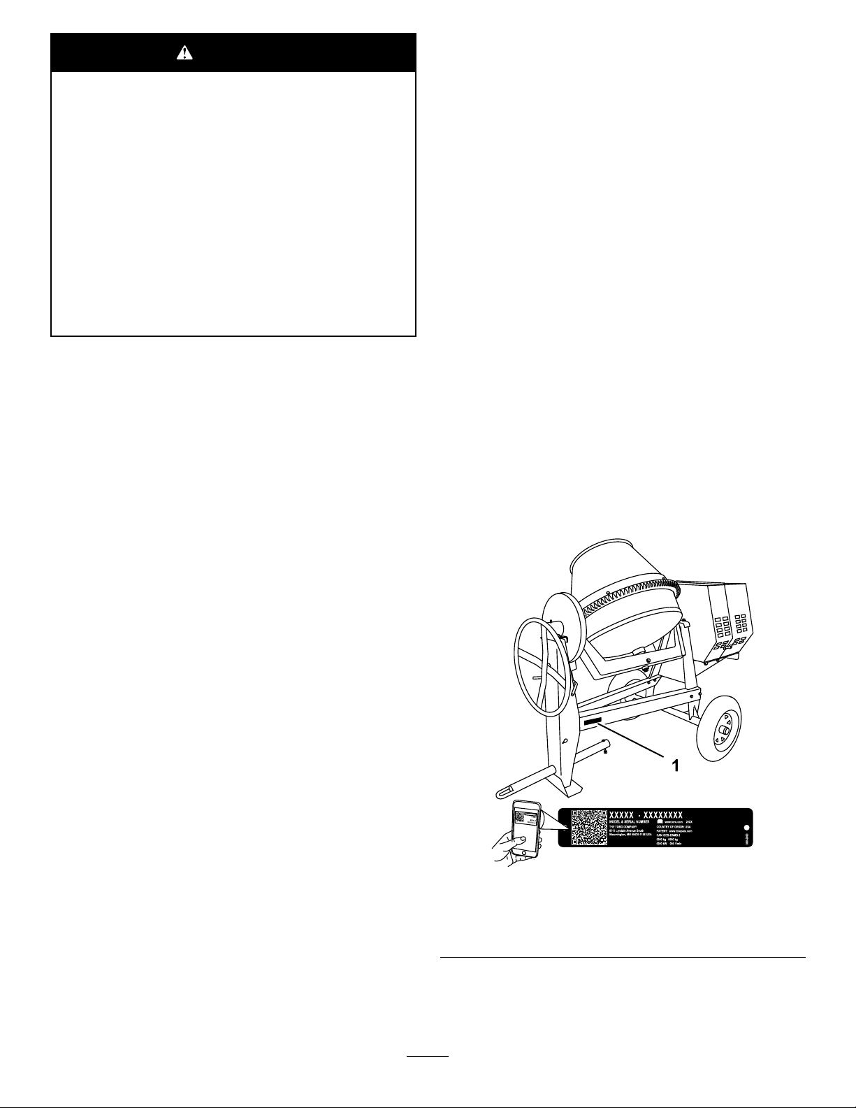
andserialnumbersofyourproductready .Figure1
andFigure2identifythelocationofthemodeland
serialnumbersontheproduct.Writethenumbersin
thespaceprovided.
Important:Withyourmobiledevice,youcan
scantheQRcodeontheserialnumberdecal(if
equipped)toaccesswarranty,parts,andother
productinformation.
Theenclosedengineowner'smanualissupplied
forinformationregardingtheUSEnvironmental
ProtectionAgency(EPA)andtheCaliforniaEmission
ControlRegulationofemissionsystems,maintenance,
andwarranty.Replacementsmaybeorderedthrough
theenginemanufacturer.
TheDOTtireinformationislocatedonthesideof
eachtire.Thisinformationgivesloadandspeed
ratings.Replacementtiresshouldhavethesameor
betterratings;refertoSpecications(page15)to
ensurethatthetiresonyourmachinemeetorexceed
theweightrequirementsofyourmachine.
g241810
Figure1
Side-DumpModels
1.Modelandserialnumberlocation
©2017—TheToro®Company
8111LyndaleAvenueSouth
Bloomington,MN55420
Contactusatwww.Toro.com.
2
PrintedintheUSA
AllRightsReserved
Page 3
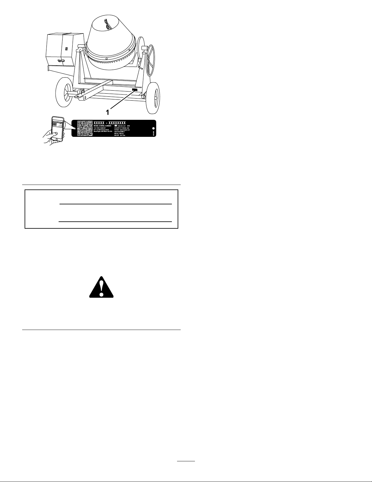
Figure2
End-DumpModels
1.Modelandserialnumberlocation
ModelNo.
SerialNo.
Thismanualidentiespotentialhazardsandhas
safetymessagesidentiedbythesafety-alertsymbol
(Figure3),whichsignalsahazardthatmaycause
seriousinjuryordeathifyoudonotfollowthe
recommendedprecautions.
Figure3
Safety-alertsymbol
Thismanualuses2wordstohighlightinformation.
Importantcallsattentiontospecialmechanical
informationandNoteemphasizesgeneralinformation
worthyofspecialattention.
Contents
Safety.......................................................................4
SafeOperatingPractices....................................4
SafetyandInstructionalDecals..........................7
Setup......................................................................10
1InstallingtheT owPole...................................10
2InstallingtheT ongue......................................10
3InstallingtheSafetyChain...............................11
ProductOverview...................................................13
Controls...........................................................14
EngineControls............................................14
Specications..................................................15
Operation................................................................16
ThinkSafetyFirst..............................................16
TowingtheMachine..........................................16
g241813
g000502
PreparingtoUsetheMachine...........................22
LoweringtheStabilizerLegs.............................22
OpeningtheCowl.............................................23
ClosingtheCowl...............................................23
AddingFuel......................................................23
PerformingDailyMaintenance..........................25
StartingtheEngine...........................................25
ShuttingOfftheEngine.....................................26
MixingtheMaterial...........................................26
DumpingtheMaterial........................................27
CleaningtheDrum............................................28
Maintenance...........................................................29
RecommendedMaintenanceSchedule(s)...........29
Pre-MaintenanceProcedures..............................29
PreparingtheMachineforMaintenance............29
DisconnectingtheSpark-PlugWire..................30
RemovingtheDividerPlate..............................30
InstallingtheDividerPlate................................30
Lubrication..........................................................31
LubricatingtheMachine....................................31
EngineMaintenance...........................................31
ServicingtheAirCleaner..................................31
ServicingtheEngineOil....................................32
ServicingtheSparkPlug...................................34
CleaningtheSparkArrester..............................35
FuelSystemMaintenance...................................36
CleaningtheFuel-SedimentCup......................36
DriveSystemMaintenance..................................37
TireAirPressure...............................................37
InspectingtheTires..........................................37
TorquingtheWheelLugNuts............................38
BeltMaintenance................................................38
CheckingtheDrive-BeltTension.......................38
AdjustingtheDrive-beltTension........................39
ReplacingtheDriveBelts..................................39
Cleaning..............................................................40
CleaningtheMachine.......................................40
Storage...................................................................41
Troubleshooting......................................................42
3
Page 4

Safety
Improperuseormaintenancebytheoperatoror
ownercanresultininjury.T oreducethepotential
forinjury ,complywiththesesafetyinstructions
andalwayspayattentiontothesafety-alertsymbol
(Figure3),whichmeans:Caution,Warning,or
Danger—personalsafetyinstruction.Failureto
complywiththeinstructionmayresultinpersonal
injuryordeath.
SafeOperatingPractices
Thisproductiscapableofamputatinghands.Always
followallsafetyinstructionstoavoidseriousinjuryor
death.
WARNING
Machiningorhandlingstone,masonry,
concrete,metal,andothermaterialscan
generatedust,mists,andfumescontaining
chemicals,suchassilica,knowntocause
seriousorfatalinjuryorillness,suchas
respiratorydisease,silicosis,cancer,birth
defects,orotherreproductiveharm.
•Controldust,mist,andfumesatthe
sourcewherepossible.Usewaterfordust
suppressionwhenfeasible.
•Usegoodworkpracticesandfollowthe
recommendationsofthemanufactureror
suppliers,OSHA,andotheroccupational
andtradeassociations.
•Alwaysfollowrespiratoryprecautions.
•Whenyoucannoteliminatethehazards
frominhalation,youandanybystanders
shouldweararespiratorapprovedby
OSHAforthematerialbeinghandled.
WARNING
Engineexhaustcontainscarbonmonoxide,
anodorless,deadlypoisonthatcankillyou.
Donotruntheengineindoorsorinan
enclosedarea.
Training
•ReadtheOperator'sManualandothertraining
material.Iftheoperator(s)ormechanic(s)cannot
readorunderstandtheinformation,itisthe
owner'sresponsibilitytoexplainthismaterialto
them.
•Becomefamiliarwiththesafeoperationofthe
equipment,operatorcontrols,andsafetysigns.
•Alloperatorsandmechanicsshouldbetrained.
Theownerisresponsiblefortrainingtheusers.
•Neverletchildrenoruntrainedpeopleoperateor
servicetheequipment.Localregulationsmay
restricttheageoftheoperator.
•Theowner/usercanpreventandisresponsible
foraccidentsorinjuriestopeopleordamageto
property.
Towing
Checkwithyourlocalcountyorstatetowingsafety
regulationsbeforetowingthemachine.
•Toreducethepossibilityofanaccidentwhile
transportingthemachineonpublicroads,ensure
thatthetowingvehicleismechanicallysoundand
ingoodoperatingcondition.
•Shutofftheenginebeforetransportingthe
machine.
•Whentowingwithaballhitch,ensurethattheball
hitchyouareusingisthepropersizeforthehitch
coupleronthemachine.
•Whentowingwithapintlehitch,ensurethatthe
eyeofthetowpoleisthecorrectdimensionfor
thepintlehook.
•Donottowwithoutthesafetypininsertedintothe
topofthereceiver.
•Inspectthehitchandcouplingforwear.Nevertow
themachinewithdamagedordefectivehitches,
couplings,chains,orothercomponents.
•Checkthetireairpressureonthetowingvehicle
andthemachine.
•Checkthetiretreadandsidewallfordamageand
wear.
•Properlyattachthesafetychainstothetowing
vehicle.
•Ensurethatthedirectionalandbrakelightsare
workingproperly(ifthemachineisequippedwith
thelightkit).
•Ensurethatthedirectional,backup,andbrake
lightsofthetowvehicleareworkingproperly(if
equipped).
•Beforetowing,ensurethatyourmachineis
correctlyandsecurelyattachedtothetowing
vehicle.
•Ensurethatthesafetychainsareproperlysecured
tothevehicle,andleaveenoughslackforturning.
•Donotcarryanymaterialinthemachinewhen
towing.
•Avoidsuddenstopsandstarts.Thiscancause
skidding,orjackkning.Smooth,gradualstarts
andstopswillimprovetowing.
•Avoidsharpturnstopreventrolling.T owonlywith
avehiclethathasahitchdesignedfortowing.Do
4
Page 5

notattachtowedequipmentexceptatthehitch
point.
•Donottowthemachinefasterthan88km/h(55
mph).
•Usecautionwhenbackingup;useaspotter
outsidethevehicletoguideyou.
•Donotallowanyonetositorrideonthemachine.
•Disconnectthemachinefromthetowvehicle
beforeusingit.
•Securethemachinefrommovementbeforeyou
towit.
•Placechockblocksunderneaththetirestoprevent
themfromrollingwhilethemachineisparked.
Preparation
Becomefamiliarwiththesafeoperationofthe
equipment,operatorcontrols,andsafetysigns.
•Useonlyaccessoriesandattachmentsapproved
bythemanufacturer.
•Wearpersonalprotectiveequipment(PPE)and
appropriateclothing,includingthefollowing:
–Hardhat
–Respiratorordustmask
–Faceshield
–Safetyglasses
–Hearingprotection
–Substantial,slip-resistantfootwear
–Longpants
–Shirtwithlongsleevesthataretightatthe
wrists
–Tight-ttinggloveswithoutdrawstringsorloose
cuffs
•Securelooseclothing,tiebacklonghair,anddo
notwearloosejewelry.
•Operatingtheequipmentsafelyrequiresthefull
attentionoftheoperator.Donotwearradioor
musicheadphoneswhileoperatingthemachine.
•Useextracarewhenhandlingfuels.Theyare
ammableandthevaporsareexplosive.Usethe
followingpracticeswhenhandlingfuel:
–Useonlyanapprovedfuelcontainer.
–Neverremovethefuelcaporaddfuelwiththe
enginerunning.
–Allowtheenginetocoolbeforerefueling.
–Donotsmoke.
–Neverrefuelordrainthemachineindoors.
–Installthefuelcapandtightenitsecurely.
–Keepthecontainernozzleincontactwiththe
tankduringlling.
–Neverllacontainerwhileitisinsideavehicle,
trunk,pickupbed,oranysurfaceotherthan
theground.
–Neverstorethemachineorfuelcontainer
insidewherethereisanopename,suchas
nearawaterheaterorfurnace.
–Ifyouspillfuel,wipeitofftheengineand
equipment.
•Ensurethatthemachineisonalevelsurface
beforeoperatingthemachine.
•Chockthetiresofthemachinetoprevent
unintendedmovement.
•Beforeeveryuse,dothefollowing:
–Inspectthecoupler,ball,andhitch.
–Ensurethatalllightsarefunctioningproperly
(ifequipped).
–Ensurethatthetiresareproperlyinatedas
recommended.
–Ensurethatthewheellugnutsaretightand
torquedproperly.
–Ensurethatthemachineisproperlysecured.
Operation
•Neverruntheengineinanenclosedorpoorly
ventilatedarea.
•Operatethemachineonlyingoodlighting
conditions.
•Beforestartingthemachine,ensurethatthere
arenopersonsorobstaclesnearorunderthe
machine.
•Shutofftheenginebeforeleavingthemachinefor
anyreason.
Neverleavearunningmachineunattended.
Alwaysshutofftheengineandverifythatall
movingpartshavestopped.
•Chockthetiresofthemachineorkeepitattached
tothetowingvehiclewhenitisnotinuse,to
preventitfromrolling.
•Avoidprolongedbreathingofexhaustfumes.
Engineexhaustfumescancausesicknessor
death.
•Keepyourhandsawayfromanymovingparts.
Keepyourfeetawayfromthetiresandthefront
post.
•Donotoperatethemachinewhileill,tired,or
undertheinuenceofalcoholordrugs.
•Ensurethattheareaisclearofotherpeopleor
petsbeforeoperatingthemachine.Stopthe
machineifanyoneentersthearea.
•Neverplaceyourhandsoranysolidobjectintothe
drumwhenthemachineisinoperation.
5
Page 6

•Donottouchpartswhichmaybehotfrom
operation.Allowthemtocoolbeforeattemptingto
maintain,adjust,orservicethemachine.
•Nevermovethemachinewhiletheengineis
running.
•Keepthecowlclosedandlatchedduringoperation.
•Ensurethatalltheguardsandshieldsaresecurely
inplacebeforeoperatingthemachine.
•Ifthemixingpaddlesstrikeaforeignobjectorifthe
machineshouldstartmakinganunusualnoiseor
vibration,shutofftheengineandemptythedrum.
Waitforallmovingpartstocometoacomplete
stopandcool.Vibrationisgenerallyawarningof
trouble.Inspectforcloggingordamage.Clean
andrepairand/orreplacedamagedparts.
•Donotchangetheenginegovernorsettingor
overspeedtheengine.
•Lightningcancausesevereinjuryordeath.Ifyou
seelightningorhearthunderinthearea,donot
operatethemachine;seekshelter.
MaintenanceandStorage
•Beforeperformingmaintenance,dothefollowing:
–Parkthemachineonalevelsurface.
–Shutofftheengine.Waitforallmovementto
stopandremovethesparkplugwirebefore
adjusting,cleaning,orrepairing.
–Allowtheenginetocoolbeforeperforming
maintenanceorstoring.
–Disengageallpowerandoperationcontrols
beforemakinganyrepairs.
•Neverlubricate,service,repair,oradjustthe
machinewhileitisrunning.
•Keepequipmentmaterialsclearfromthemufer
andenginetohelppreventres.Wipeupany
spilledoilorfuel.
•Neverallowuntrainedpersonneltoservicethe
machine.
•Keepyourhands,feet,andclothingawayfrom
movingparts.Ifpossible,donotmakeadjustments
withtheenginerunning.
•Keepallpartsingoodworkingconditionandall
hardwaretightened.Replaceallwornordamaged
decals.
•Removeanybuildupofgrease,oil,ordebrisfrom
themachine.
•Stopthemachine,shutofftheengine,andinspect
themachineifaforeignobjectentersthedrumor
causesanotherobstruction.Makeanynecessary
repairsbeforestartingthemachine.
•Donottamperwithsafetydevices.
•Securethemachinefrommovementandchock
thetireswhenstoringthemachine.
•Keepallnuts,bolts,screws,andhoseclamps
securelytightened.Keepthemachineingood
condition.
•UseonlygenuineT ororeplacementpartsto
ensurethattheoriginalstandardsaremaintained.
6
Page 7
SafetyandInstructionalDecals
Safetydecalsandinstructionsareeasilyvisibletotheoperatorandarelocatednearanyarea
ofpotentialdanger.Replaceanydecalthatisdamagedormissing.
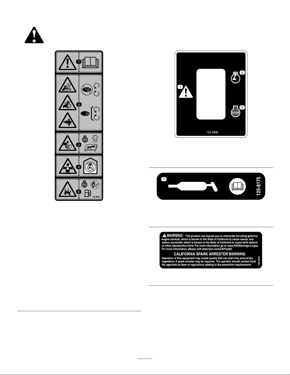
decal125-4940
125-4940
1.Warning—readthe
Operator’sManual.
2.Handandarm
entanglementatthe
beltdrive;crushinghazard
ofhand;entanglement
hazardofhandatthe
shaft—keepyourhands
awayfrommovingparts;
keepallguardsand
shieldsinplace.
3.Entanglementhazard
atpaddles—shutoff
theengineandwait
forallmovingpartsto
stopbeforeperforming
maintenance.
1.Warning
2.Engine—run
decal125-4939
125-4939
4.Toxicgasinhalation
hazard—Donotrunthe
engineinanenclosed
space.
5.Explosionhazard—shut
offtheengineandkeep
awayfromameswhen
refueling.
1.ReadtheOperator’sManualforinformationongreasing
themachine.
3.Engine—shutoff
decal125-8175
125-8175
decal133-5619
133-5619
7
Page 8
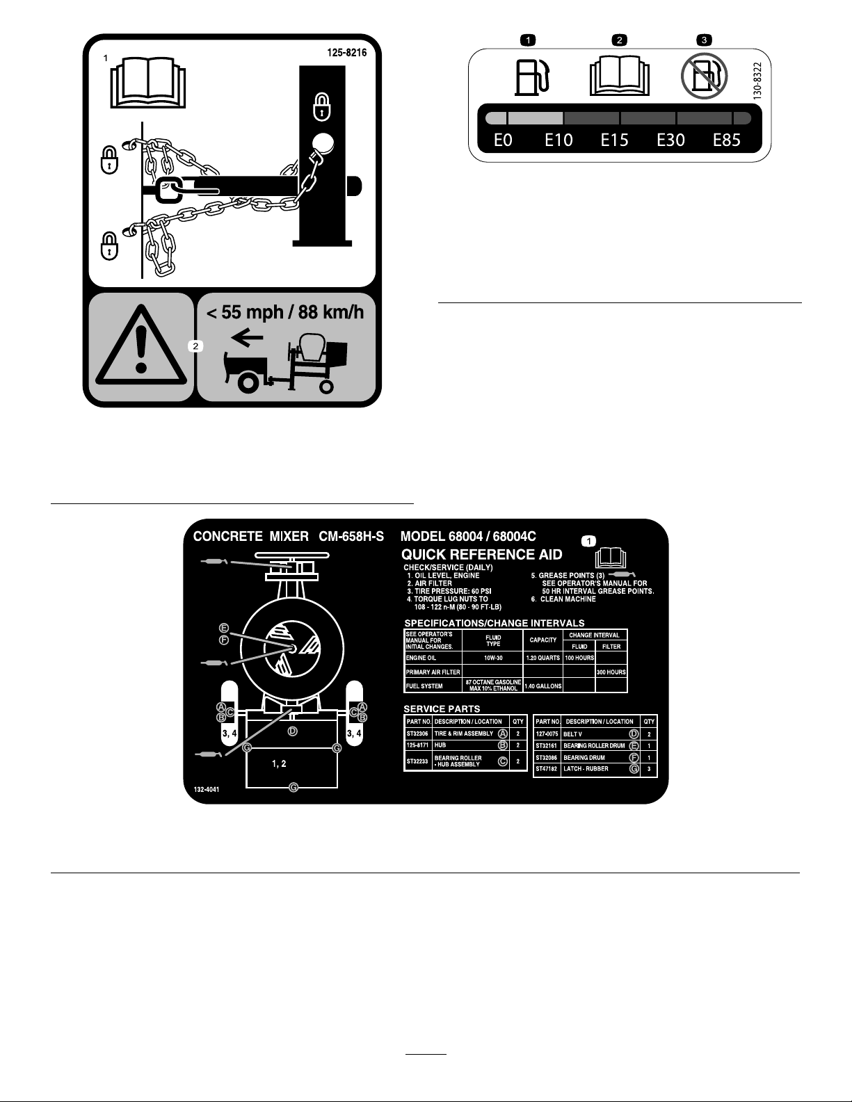
decal130-8322
130-8322
1.ReadtheOperator’s
Manualforinformationon
howtotowthemachine.
125-8216
2.Warning—limittowing
speedtolessthan88km/h
(55mph).
1.Onlyusefuelwithan
alcoholcontentbyvolume
under10%.
3.Donotusefuelwithan
alcoholcontentbyvolume
greaterthan10%.
2.ReadtheOperator's
Manualformore
informationonfuel.
decal125-8216
1.ReadtheOperator'sManualformoreinformationonservicingthemachine.
decal132-4041
132-4041
8
Page 9
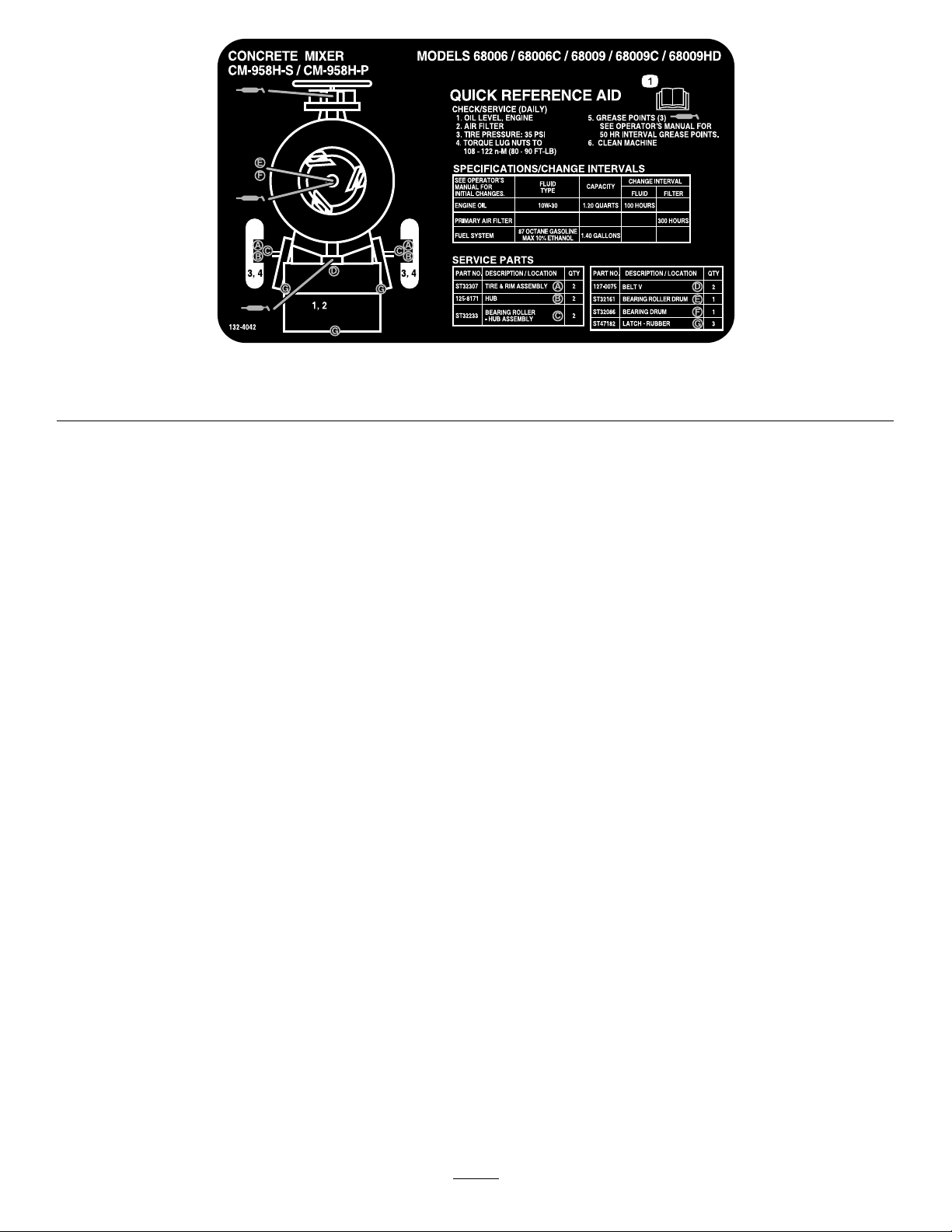
1.ReadtheOperator'sManualformoreinformationonservicingthemachine.
decal132-4042
132-4042
9
Page 10
Setup
LooseParts
Usethechartbelowtoverifythatallpartshavebeenshipped.
ProcedureDescription
1
2
3
Towpolekit(soldseparately)
Tongue1
Frontstabilizerleg1
Shortbolt
Longbolt1
Nut
Safetychain
Connectinglink
1
InstallingtheTowPole
Side-DumpModelsOnly
Partsneededforthisprocedure:
Qty.
Use
1
6
7
1
2
Installthetowpole(side-dumpmodels
only).
Installthetongue(end-dumpmodels
only).
Installthesafetychain.
1
Towpolekit(soldseparately)
TowPoleSpecications
Purchasethetowpolekit(includingfasteners)that
meetsyourneedsfromyourAuthorizedService
Dealer.Themachinehasthefollowingtowpole
options:
HitchTypeLength
50mm(2inch)ball—stamped78.7cm(31inches)or127cm
50mm(2inch)ball—forged78.7cm(31inches)or127cm
Pintle
(50inches)
(50inches)
78.7cm(31inches)or127cm
(50inches)
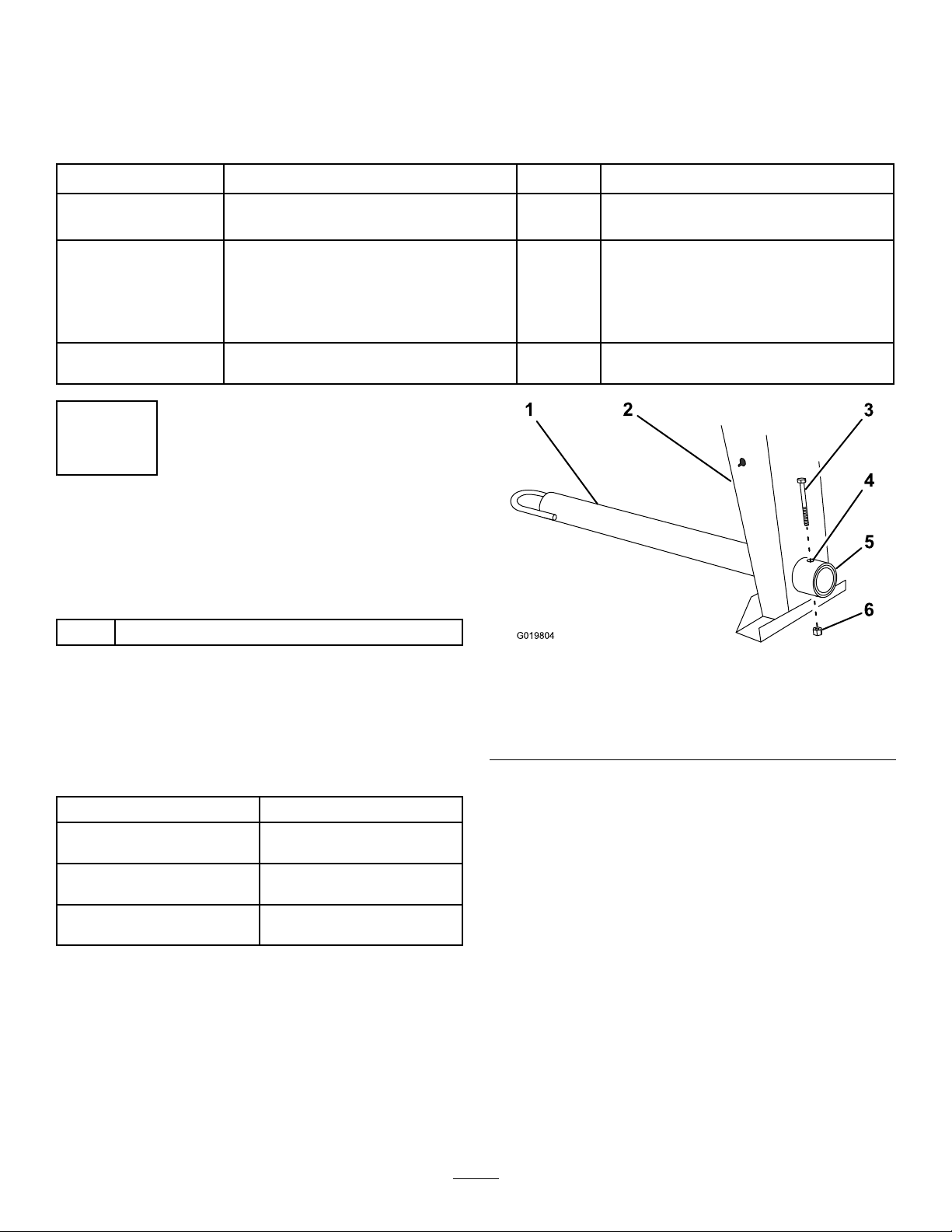
InstallingtheTowPole
1.Removetheboltandnutfromthetowpole
(Figure4).
Figure4
1.Towpole4.Bolthole
2.Frontpost
3.Bolt6.Nut
2.Slidethetowpoleforwardandaligntheholein
thepolewiththeholeintheframetting(Figure
4).
3.Inserttheboltthroughtheholesinthettingand
thepole(Figure4).
4.Threadthenutontotheboltandtightenthem
untiltheyaretightagainsttheframetting
(Figure4).
5.Frametting
Note:Iftheself-lockingnyloninsertinthe
locknutwearswithuse,replacethenutwitha
newGrade5orGrade8locknut.
g019804
10
Page 11
2
InstallingtheTongue
End-DumpModelsOnly
Partsneededforthisprocedure:
1Tongue
1Frontstabilizerleg
6
Shortbolt
1Longbolt
7
Nut
Procedure
1.Lowertherearstabilizerlegs;refertoLowering
theStabilizerLegs(page22).
2.Placejackstandsunderthefrontframerail
topreventthemachinefromtippingforward
(Figure5).
WARNING
Mechanicalorhydraulicjacksmayfailto
supportthemachineandcauseserious
injury.
Usejackstandswhensupportingthe
machine.
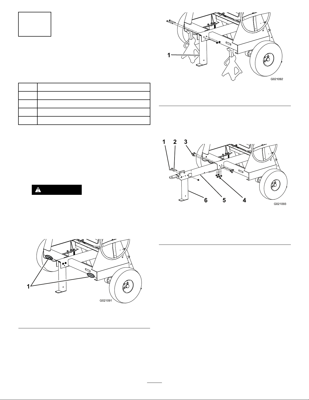
Figure6
1.Frontstabilizerleg
4.Installthetongueintotheopeningatthefront
ofthemachineandsecureitwith6nutsand
shortboltstorquedto102N∙m(75ft-lb);refer
toFigure7.
Figure7
1.Clevispin
2.Longbolt5.Tongue
3.Shortbolt
4.Nut
6.Frontstabilizerleg
g021092
g021093
Figure5
1.Supportpoints
3.Removethe2nutsandboltsthatsecurethe
frontstabilizerlegtotheframe(Figure6)and
removethefrontstabilizerleg.
5.Alignthetoprearholeinthefrontstabilizerleg
totheholepastthehandleinthefrontofthe
tongue(Figure7).
6.Installthelongboltthroughtheholesandsecure
itwithanuttorquedto102N∙m(75ft-lb);refer
toFigure7.
Note:Thestabilizerlegpivotsrearwardonthe
g021091
11
bolt.Ifyouinstalltheboltintothewronghole,
thestabilizerlegwillnotworkproperly.
7.Inserttheclevispintolockthefrontstabilizerleg
inposition(Figure7).
Page 12
3
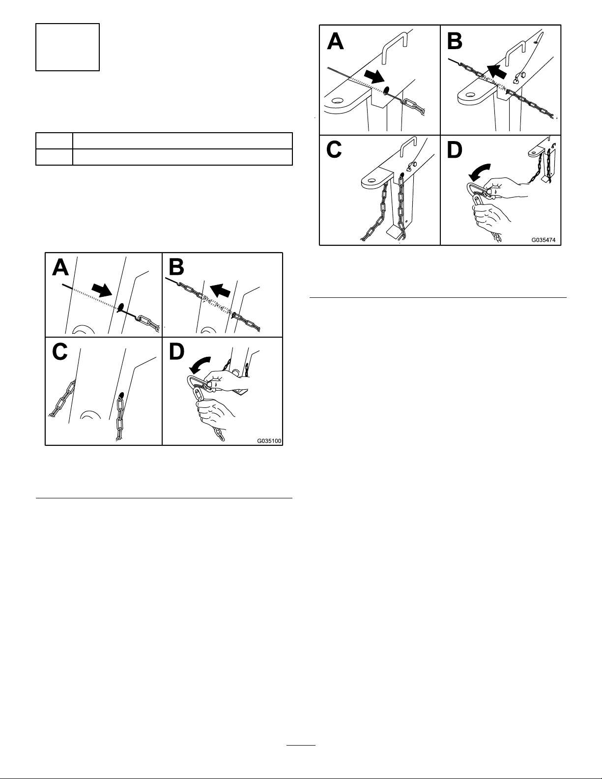
InstallingtheSafetyChain
Partsneededforthisprocedure:
1
Safetychain
2
Connectinglink
Procedure
Formahookontheendofabendablepieceofrodor
stiffwire(notincluded)andinstallthesafetychainand
connectinglinksasshowninFigure8or.Figure9
g035474
Figure9
End-DumpModels
Note:Ensurethatapproximatelyequallengthsof
safetychainextendfromeithersideofthefrontpost.
Side-DumpModels
g035100
Figure8
12
Page 13
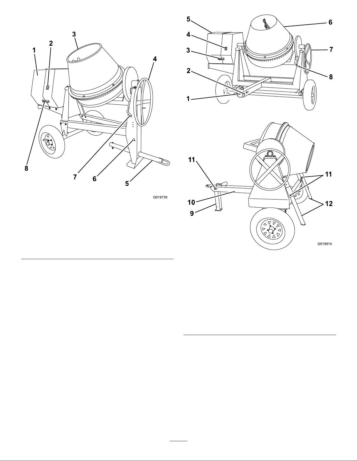
ProductOverview
Figure10
Side-DumpModels
1.Enginecowl5.Towpole
2.Engineswitch
3.Drum7.Drum-tiltbrake
4.Handwheel8.Rubberlatch
6.Safety-chainkeyholes
g019730
g019914
Figure11
End-DumpModels
1.Tongue-mountedtow
coupler
2.Safety-chainkeyholes
3.Rubberlatch9.Frontstabilizerleg
4.Engineswitch10.Rearwardpinhole
5.Enginecowl
6.Drum12.Rearstabilizerlegs
7.Handwheel
8.Drum-tiltbrake
11.Clevispin
13
Page 14
Controls
Becomefamiliarwithallofthecontrolsbeforeyou
starttheengineandoperatethemachine.
EngineSwitch
WhentheengineswitchonthecowlisintheRUN
position,itallowstheenginetorun.Movingtheengine
switchtotheSTOPpositionshutsofftheengine.
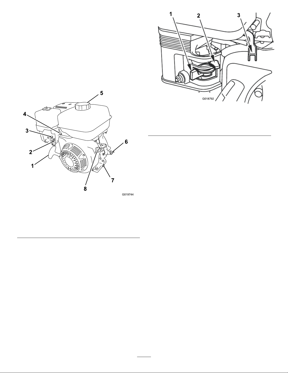
EngineControls
g018792
Figure13
1.Fuelvalve3.Throttlelever
2.Chokelever
ChokeLever
Figure12
1.Recoil-starthandle5.Fuelcap
2.Fuelvalve
3.Chokelever7.Oil-drainplug
4.Throttlelever
FuelValve
6.Oildipstick
8.On/Offswitch
Thefuelvalve(Figure13)islocatedunderneaththe
chokelever.Movetheleverforthefuelvalvetothe
ONpositionbeforeattemptingtostarttheengine.
Whenyouhavenishedmixing,shutofftheengine
andmovethefuel-valvelevertotheOFFposition.
Usethechokelever(Figure13)tostartacoldengine.
Beforepullingtherecoil-starthandle,movethechoke
levertotheCLOSEDposition.Oncetheengineis
running,movethechokelevertotheOPENposition.
Donotusethechokeiftheengineisalreadywarmed
uporiftheairtemperatureishigh.
g019744
ThrottleLever
Thethrottlelever(Figure13)controlsthespeed(rpm)
oftheengine.Itislocatednexttothechokelever.It
setstheenginespeedandthereforecanincreaseand
decreasetherotationspeedofthemixingpaddles.
Forbestperformance,setthiscontroltotheFAST
positionwhenmixingmaterial.
EngineOn/OffSwitch
TheOn/Offswitchislocatedonthefrontoftheengine.
•RotateittotheONpositiontostartandrunthe
engine.
•RotateittotheOFFpositiontoshutofftheengine.
14
Page 15

Handwheel
Thehandwheelcontrolsthetiltofthedrum.
Drum-tiltBrake
Thedrum-tiltbrakelocksthedrumintoanupright
positionoradischargingposition.
g021103
Figure14
1.OFFposition2.ONposition
Recoil-StartHandle
Tostarttheengine,pulltherecoil-starthandle(Figure
12)quicklytoturntheengineover.Theengine
controlsdescribedabovemustallbesetcorrectlyfor
theenginetostart.
Recoil-StartHandle
Tostarttheengine,pulltherecoil-starthandle(Figure
12)quicklytoturntheengineover.Theengine
controlsdescribedabovemustallbesetcorrectlyfor
theenginetostart.
Oil-LevelSwitch
Theoil-levelswitchislocatedinsidetheengine,andit
doesnotallowtheenginetorunintheeventtheoil
levelisbelowthesafeoperatinglimit.
Oil-LevelSwitch
Theoil-levelswitchislocatedinsidetheengine,andit
doesnotallowtheenginetorunintheeventtheoil
levelisbelowthesafeoperatinglimit.
Specications
Note:Specicationsanddesignaresubjecttochangewithoutnotice.
Model6800468006680076800868009
BatchCapacity
TotalV olume0.255m
DrumMaterial
Length198cm
Width1 17cm
Height147cm
Weight313kg
0.17m
(6.0ft3)
(9.0ft3)
SteelSteelSteel
(78inches)
(46inches)
(58inches)
(690lb)
3
3
0.255m
(9.0ft3)
0.43m
(15.1ft3)
213cm
(84inches)
142cm
(56inches)
165cm
(65inches)
363kg
(800lb)
3
3
0.255m
(9.0ft3)
0.43m
(15.1ft3)
216cm
(85inches)
216cm
(85inches)
180cm
(71inches)
397kg
(875lb)
3
3
0.255m
(9.0ft3)
0.43m
(15.1ft3)
PolyethylenePolyethylene
216cm
(85inches)
216cm
(85inches)
180cm
(71inches)
397kg
(875lb)
3
3
0.255m
(9.0ft3)
0.43m
(15.1ft3)
213cm
(84inches)
142cm
(56inches)
165cm
(65inches)
381kg
(837lb)
3
3
15
Page 16

Operation
Important:Beforeoperating,checkthefueland
oillevels,andremovedebrisfromthemachine.
Ensurethattheareaisclearofpeople.
TowingtheMachine
Beforetowingthemachine,readalltheinformation
andperformalltheapplicableprocedurestointhis
sectiontoensuresafeandpropertowing.
WARNING
ThinkSafetyFirst
Carefullyreadallsafetyinstructionsandsymbolsin
thismanual,ontheproductdecals,andothermedia
suppliedwiththeproduct.Knowingthisinformation
couldhelpyouorbystandersavoidinjury.
Knowhowtoquicklyshutdownthemachineinan
emergency.
Useahard-hat,hearingprotection,ashirtwithlong
sleevesthataretightatthewrists,tight-ttinggloves
withoutdrawstringsorloosecuffs,eyeprotection,and
adustmaskorrespirator.Ameshvisoralonedoes
notprovidesufcienteyeprotection;supplementwith
protectiveglasses.
CAUTION
Thismachineproducessoundlevelsthatcan
causehearinglossthroughextendedperiods
ofexposure.
Wearhearingprotectionwhenoperatingthis
machine.
Towingthemachineathighspeedincreases
theriskofahitchmalfunctionandtirefailure.
Higherspeedsalsoincreasethemomentum
ofthemachineandbrakingdistance.Ifthe
machinedetachesfromthetowvehicleathigh
speed,itcouldcausedamagetoproperty,or
injuryordeathtobystanders.
Donotexceed88km/h(55mph)whentowing
themachine.Forpoorroadconditionsor
inclementweather,reducespeedaccordingly.
WARNING
Towingthemachinewithmaterialinthedrum
increasestheriskofahitchmalfunctionand
tirefailure.Inaddition,materialcouldbounce
outofthedrumandhitothervehiclesand/or
people.Materialinthedrumincreasesthe
weight,whichaffectsmomentumandbraking
distance.
Donottowthemachinewithmaterialinthe
drum.
1.Wearhearingprotection.
Figure15
•ReviewandunderstandtheSafeOperating
Practices(page4).
•Testthebrakesofthetowvehiclebeforetowing.
•Avoidsuddenstartsandstopswhiletowingthe
g242004
machine.
TowVehicleRequirements
Beforeconnectingthemachinetoyourtowvehicle,
ensurethatyourvehicleispreparedasfollows:
•Ensurethatyourtowvehiclehastowing
capacityfortheweightofthemachine;referto
Specications(page15).
•UseaClass2orlargerreceiver.
•Ensurethatyourtowvehiclehastheappropriate
hitchtotowthemachine;optionsincludea50mm
(2inch)ballhitchorapintlehitch.
•Ifthemachineisequippedwithatrailer-lightkit,
ensurethattheelectricalconnectorofthetow
vehicleiscompatiblewiththeelectricalconnector
ofthemachine.Themachineusesastandard
4-pin,atplug.Ifyourtowvehiclehasadifferent
typeofplug,obtainanadapterfromanautomotive
partsstore.
16
Page 17

PreparingtheMachineforTowing
1.Shut-offtheengineandfuelvalve.
2.Emptythedrum.
3.Usingthehandwheel,positionthedrumsothatit
ispointingdowntowardtheground(Figure16).
g019741
Figure18
Figure16
1.Drumpointingdown3.Towpoleboltedinplace
2.Drum-tiltbrakeengaged
4.Lockthedrumintopositionbypushingdownthe
drum-tilt-brakehandle(Figure17).
g019806
6.Inspectthetires;refertoInspectingtheTires
(page37).
RaisingtheStabilizerLegs
End-DumpModelsOnly
End-dumpmodelshaveafrontstabilizerlegand2
rearstabilizerlegs.
Raisethestabilizerlegsbeforetowingthemachine.
1.Adjustthemachinesothatthereisnoweight
restingontherearstabilizerlegs.
2.Pulltheclevispinoutfrom1oftherearstabilizer
legsandthebracket(Figure19).
Figure17
Drum-TiltBrake
1.Unlockedposition2.Lockedposition
5.Closetheenginecowlandsecurethecowl
latches(Figure18).
g019733
g019917
Figure19
17
Page 18

3.Slidethestabilizerlegupinthebracketand
alignthepinholeofthebracketwiththelower
holeinthestabilizerleg(Figure19).
4.Pushtheclevispinthroughtheholeinthe
bracketandthestabilizerleg(Figure19).
5.Repeatsteps1through4fortheotherrear
stabilizerleg.
6.Liftupwardonthetonguesothatthereisno
weightrestingonthefrontstabilizerleg.
7.Pulltheclevispinoutfromthefrontstabilizerleg
andthetongue(Figure20).
HitchingtheMachinetoaTow Vehicle
Yourmachineisequippedwith1ofthefollowing
hitchtypes;hitchitasdescribedintheappropriate
procedure:
•Stamped-ballcoupler—HitchingaStamped-Ball
Coupler(page18)
•Forged-ballcoupler—HitchingaForged-Ball
Coupler(page19)
•Pintle-hitchcoupler—HitchingaPintle-Hitch
Coupler(page19)
•Pin-hitchcoupler—HitchingaPin-HitchCoupler
(page20)
HitchingaStamped-BallCoupler
1.Applychassisgreasetothesocketofthecoupler
andtheareaoftheclampthatcontactstheball.
2.Oilthepivotpointsandslidingsurfacesofthe
couplerwithSAE30motoroil.
Figure20
1.Removetheclevispin.3.Installtheclevispin.
2.Rotatethestabilizerleg
up.
8.Rotatethefrontstabilizerlegupintothetongue
(Figure20).
9.Pushtheclevispinthroughtherearwardholein
thetongueandthefrontstabilizerleg(Figure
20).
3.HitchthemachineasshowninFigure21.
g019915
18
Page 19

Figure21
HitchingaForged-BallCoupler
1.Applyremovablethread-lockingcompoundto
thethreadsofthecouplerbolttopreventthe
couplerhandlefromcomingloose.
g035115
Figure22
Note:Useawrenchtokeeptheboltfrom
spinning.
HitchingaPintle-HitchCoupler
g035113
Important:Applythread-lockingcompound
asneededinthefuture.
2.Applychassisgreasetothesocketofthecoupler
andtheareaoftheclampthatcontactstheball.
3.HitchthemachineasshowninFigure22.
g035164
Figure23
19
Page 20

HitchingaPin-HitchCoupler
Figure24
Note:Usea19mm(3/4inch)or22mm(7/8inch)
hitchpin.
g021177
Figure25
g035116
1.Connectinglinks3.Chaincrossedundertow
2.Keyholesinfrontpost
Side-DumpModels
pole
ConnectingtheSafetyChainsto theTowVehicle
1.Pullthesafetychainthroughtheslotsinthe
keyholes,sothatthelengthsoneachsideare
equal.
2.Crossbothlengthsofchainunderthetow
pole(underthetongueforend-dumpmodels).
Forside-dumpmodels,refertoFigure25.For
end-dumpmodels,refertoFigure26.
Note:Crossingthechainsdecreasesthe
chancesofthefrontofthemachinedropping
tothegroundifthehitchdoesnotholdthe
connection.
Figure26
End-DumpModels
1.Connectinglinks3.Chaincrossedunder
2.Keyholes
tongue
4.Chain
3.Connecteachlengthofchaintothesafety
chainmountingpointonthetowvehiclewiththe
connectinglinks(Figure27).
Important:Ensurethatthechainhas
enoughslackforturningaroundcorners
whentowingthemachine.
Note:Forside-dumpmodels,stowtheexcess
chaininsidethebottomofthefrontpostby
pushingitintothekeyholesandlatchingthe
appropriatelinksintothekeyholeslots.
g019928
Note:Forend-dumpmodels,connectthe
connectinglinkstotheappropriatelinksinthe
safetychain(Figure27).Iftheexcesschain
hangstoolowandtouchestheground,connect
20
Page 21

itagaintotheconnectinglinktoraiseitaway
fromtheground.
Figure27
1.Connectinglink3.Chainlink
2.Safetychainmounting
pointontowvehicle
4.Chain
C.Operateeachturnsignalofthetowvehicle
inturn.
Thecorrespondingturn-signallightsofthe
machineshouldilluminate.
g020365
ConnectingandCheckingthe Lights
MachinesEquippedwithaLightKitOnly
1.Connecttheelectricalplugofthemachinewith
theelectricalplugofthetowvehicle(Figure28).
Figure28
Note:Themachineusesastandard4-pin,at
plug.Ifyourtowvehiclehasadifferenttype
ofplug,obtainanadapterfromanautomotive
partsstore.
2.EnsurethatthetowvehicleisintheNEUTRAL
position,engagetheparkingbrake,andstart
theengine.
g020828
3.Testthelightsasfollows:
A.Turnontheheadlightsofthetowvehicle.
Thetaillightsofthemachineshould
illuminate.
B.Pressthebrakepedalofthetowvehicle.
Thebrakelightsofthemachineshould
illuminate.
21
Page 22

PreparingtoUsethe Machine
1.Parkthemachineonalevelsurfaceand
disconnectthemachinefromthetowvehicle.
2.Ensurethatallguardsandpaddlesareinplace
andingoodcondition.
3.Performalldailymaintenanceprocedures
prescribedinMaintenance(page29).
4.Chockthefrontandbackofthetirestoprevent
themachinefrommoving.
5.Forend-dumpmodels,lowerthefrontandrear
stabilizerlegs;refertoLoweringtheStabilizer
Legs(page22).
6.Movethedrumtotheuprightpositionandlockit.
LoweringtheStabilizer Legs
4.Repeatsteps1through3fortheotherrear
stabilizerleg.
5.Liftupwardonthetonguetoprovideclearance
forthefrontstabilizerleg.
6.Pulltheclevispinoutfromthefrontstabilizerleg
andthetongue(Figure30).
End-DumpModelsOnly
End-dumpmodelshaveafrontstabilizerlegand
2rearstabilizerlegstokeepthemachinefrom
tippingforwardorbackwardduringoperation.Move
thestabilizerlegsintotheloweredpositionbefore
operatingthemachine.
1.Pulltheclevispinoutfrom1stabilizerlegand
thebracket(Figure29).
g019916
Figure30
1.Removetheclevispin.3.Installtheclevispin.
2.Rotatethestabilizerleg
down.
7.Rotatethefrontstabilizerlegdowntowardthe
ground(Figure30).
8.Pushtheclevispinthroughthefrontholeinthe
tongueandthefrontstabilizerleg(Figure30)
andcarefullylowerthemachinetotheground.
Figure29
2.Slidethestabilizerlegdowninthebracketand
alignthepinholeofthebracketwiththeupper
holeinthestabilizerleg(Figure29).
3.Pushtheclevispinthroughtheholeinthe
bracketandthestabilizerleg(Figure29).
g019918
22
Page 23

OpeningtheCowl
AddingFuel
DANGER
Incertainconditions,fuelisextremely
ammableandhighlyexplosive.Areor
explosionfromfuelcanburnyouandothers
andcandamageproperty.
•Fillthefueltanksoutdoors,inanopen
area,whentheengineiscold.Wipeupany
fuelthatspills.
•Neverllthefueltanksinsideanenclosed
trailer.
•Neversmokewhenhandlingfuelandstay
awayfromanopenameorwherefuel
fumesmaybeignitedbyaspark.
•Storefuelinanapprovedcontainerand
keepitoutofthereachofchildren.Never
buymorethana30-daysupplyoffuel.
ClosingtheCowl
Figure31
g035134
•Donotoperatewithoutentireexhaust
systeminplaceandinproperworking
condition.
DANGER
Incertainconditionsduringfueling,static
electricitycanbereleased,causingaspark
thatcanignitethefuelvapors.Areor
explosionfromfuelcanburnyouandothers
andcandamageproperty.
•Alwaysplacefuelcontainersontheground
awayfromyourvehiclebeforelling.
•Donotllfuelcontainersinsideavehicle
oronatruckortrailerbed,becauseinterior
carpetsorplastictruckbedlinersmay
insulatethecontainerandslowthelossof
anystaticcharge.
•Whenpractical,removeequipmentfrom
thetruckortrailerandrefueltheequipment
withitswheelsontheground.
Figure32
•Ifthisisnotpossible,thenrefuelsuch
equipmentonatruckortrailerfroma
portablecontainerratherthanfroma
fuel-dispensernozzle.
g035135
•Ifyoumustuseafuel-dispensernozzle,
keepthenozzleincontactwiththerimof
thefueltankorcontaineropeningatall
timesuntilfuelingiscomplete.
23
Page 24

WARNING
Fuelisharmfulorfatalifswallowed.
Long-termexposuretovaporscancause
seriousinjuryandillness.
•Avoidprolongedbreathingofvapors.
•Keepyourfaceawayfromthenozzleand
fueltankopening.
•Keepfuelawayfromyoureyesandskin.
FuelRecommendations
•Forbestresults,useonlyclean,fresh(lessthan
30daysold),unleadedgasolinewithanoctane
ratingof87orhigher((R+M)/2ratingmethod).
•Ethanol:Gasolinewithupto10%ethanol
(gasohol)or15%MTBE(methyltertiarybutyl
ether)byvolumeisacceptable.Ethanoland
MTBEarenotthesame.Gasolinewith15%
ethanol(E15)byvolumeisnotapprovedforuse.
Neverusegasolinethatcontainsmorethan
10%ethanolbyvolume,suchasE15(contains
15%ethanol),E20(contains20%ethanol),orE85
(containsupto85%ethanol).Usingunapproved
gasolinemaycauseperformanceproblemsand/or
enginedamagewhichmaynotbecoveredunder
warranty.
•Donotusegasolinecontainingmethanol.
FillingtheFuelTank
1.Parkthemachineonalevelsurface,shutoffthe
engine,andallowtheenginetocool.
2.Cleanaroundthefuelcapandremoveit(Figure
33).
g019799
Figure33
1.Fuelcap
•Donotstorefueleitherinthefueltankorinfuel
containersoverthewinterunlessyouuseafuel
stabilizer.
•Donotaddoiltogasoline.
Important:T oreducestartingproblems,addfuel
stabilizertothefuelallseason,mixingitwithfuel
lessthan30daysold;runthemachinedrybefore
storingitformorethan30days.
Donotusefueladditivesotherthanafuel
stabilizer/conditioner.Donotusefuelstabilizers
withanalcoholbasesuchasethanol,methanol,
orisopropanol.
FuelTankCapacity
5.3L(1.4USgallons)
3.Addfueltothefueltankuntilthelevelisatthe
maximumfuellevel(Figure34).
Important:Thisspaceinthetankallows
fueltoexpand.Donotllthefueltank
completelyfull.
24
Page 25

StartingtheEngine
1.EnsurethattheclutchleverisintheOFF
position.
2.MovethefuelvalvetotheOPENposition,allthe
waytotheright(Figure35).
Figure34
1.Maximumfuellevel
4.Installthefuelcapsecurely(Figure33).
5.Wipeupanyspilledfuel.
PerformingDaily Maintenance
Beforestartingthemachineeachday ,performthe
EachUse/DailyprocedureslistedinMaintenance
(page29).
g020679
g019815
Figure35
1.Chokelever
2.Fuelvalve
3.Throttlelever
3.MovethechokelevertotheONposition(Figure
35).
Note:Awarmorhotenginemaynotrequire
choking.
4.Movethethrottlelever1/3ofthewaytowardthe
MAXposition.
5.MovetheengineswitchtotheONposition
(Figure36).
1.Engineswitch—OFF
position
25
g021103
Figure36
2.Engineswitch—ON
position
Page 26

6.Pullthestarterhandlelightlyuntilyoufeel
resistance,thenpullthehandlebriskly(Figure
37).Returnthestarterhandlegently.
MixingtheMaterial
ConcreteBasics
DANGER
Eyeandskincontactwithconcretematerials
andbreathingthedustinvolvedishazardous
toyourhealth.
•Ensurethatthereisadequateair
ventilation.
•Wearadustmasktopreventinhalationof
dustwhileusingthemachine;refertoSafe
OperatingPractices(page4).
Figure37
7.Aftertheenginestarts,graduallymovethe
chokeleverbacktotheOFFposition.Ifthe
enginestallsorhesitates,movethechokeback
totheONpositionagainuntiltheenginewarms
up.ThenmoveittotheOFFposition.
ShuttingOfftheEngine
Inanemergency,shutofftheenginequicklyby
pressingtheEmergencyShutoffswitchlocatedon
thecowl,holdingituntiltheengineandmovingparts
havestopped.
1.MovethethrottlelevertotheMINposition
(Figure35).
Note:Iftheenginehasbeenworkinghardor
ishot,letitidleforaminutebeforeshuttingoff
theengine.Thishelpstocooltheenginebefore
shuttingitoff.Inanemergency ,shutoffthe
engineimmediately.
2.MovetheengineswitchtotheOFFposition.
3.MovethefuelvalvetotheCLOSEDposition,all
thewaytotheleft.
g019747
•Avoiddirectcontactofcementand
concretematerialswithskinandeyes.
Note:Followthemanufacturer’sinstructionsthatare
printedonthepackagingoftheproductthatyouare
using.
Concretehasthefollowing4basicingredients:
•Sand
•Gravel
•Portlandcement
•Water
Dependingontheapplication,youcanusedifferent
ratiosofthese4ingredients.Thetypicalratiofor
mixingconcreteis1partPortlandcement,2parts
sand,and3partsgravel.
Therearemanyvariationsofconcretemixrecipes,
dependingontheapplication.Itisimportanttouse
theappropriatequantityofwater.Usingtoolittlewater
resultsindryareasinthemix,butusingtoomuch
waterresultsinweakerconcrete.Theamountofwater
neededvariesdependingonmoisturecontentofthe
sandandgravel.Themixshouldhaveathickness
similartopeanutbutter.
Keepthepouredconcretedampforseveraldaysto
obtainpropercuring.Evaporationresultsinweaker
concrete.Concretecuresthroughhydration,a
reactionbetweenwaterandcement.
26
Page 27

PreparingtoMix
MixingConcrete
DANGER
Thismachineiscapableofamputatinghands.
•Keepallbystandersasafedistanceaway
fromthemachine.
•Stopthemachineimmediatelyifany
peopleoranimalsentertheworkarea.
•Neverplaceanypartofyourbodyintoa
positionthatcausesanunsafeoperating
condition.
1.ReadalltherecommendationsfromSafe
OperatingPractices(page4)beforeusingthe
machine.
2.Ensurethatthemachineisonlevelgroundand
thesurroundingareaisclearofobstacles.
3.Removethemachinefromthetowvehicle.
4.Securethemachinefrommovement.
5.Usethehandwheeltomovethedrumintoan
upright,slightlytiltedpositiontoallowaccessfor
pouringmaterialsintothedrum.
Note:Thispositionalsoallowsthemixing
paddlestomixthematerialsmoreeffectively.
Important:Donotaddmorematerialthanthe
batchcapacityforyourspecicmachinemodel;
refertoSpecications(page15).
1.Ensurethatthetiltbrakeisfullyengagedand
thatthedrumisoperatingatfullspeed.
2.Pourwaterintothedrum.
3.Addtheconcreteingredientsasfollows:
•Ifyouareusingpre-mixedconcrete,addthe
requiredamountofdrypre-mix.
•Ifyouaremixingsand,gravel,andcement,
addthemasfollows:
A.Addtherequiredamountofgravel.
Note:Addingwaterandgravelbefore
cementandsandallowsthemixleftin
thedrumfromthepreviousbatchtobe
tumbledoffthedrumandpaddlesand
intothenextbatch.
B.AddtherequiredamountofPortland
cement.
C.Addtherequiredamountofsand.
4.Allowthedrumtoturnwhilethemixreachesthe
appropriateconsistency.
6.Pushthedrum-tiltbrakedowntolockthedrum
intopositionandavoidaccidentallydumpingthe
material.
7.Starttheengine.Allowtheenginetowarmup
atidlefor2minutes;refertoStartingtheEngine
(page25).
Important:Ifyouneedtoshutoff
themachinequickly,usetheengine
switch/speed-controlhandle(asequipped)
locatedonthecowl;refertoEngineSwitch
(page14).
8.Usetheenginethrottlelever/speed-control
handle(asequipped),tocontrolthespeedof
theengineanddrum.
9.Closetheenginecowl.
DumpingtheMaterial
Note:Whendumpingabatchofmaterial,leavethe
enginerunningsothattherotatingdrumhelpsdump
thematerial.
1.Alignawheelbarroworsimilarcontainerof
adequatecapacityinthepathofthedrum
opening.
2.Whilethedrumisturning,rmlygraspthe
handwheelwith1hand.
3.Usingyourotherhand,pullupwardonthe
drum-tilt-brakehandletoreleasethebrake.
4.Usebothhandstoslowlyturnthehandwheel,
allowingthedrumtotiltinthedesireddirection
anddumpthedesiredamountofmaterial.
5.Turnthehandwheelintheoppositedirectionto
returnthedrumintoanuprightposition.
6.Pushdownonthedrum-tiltbraketolock
thedrumintoposition,avoidingaccidental
dischargingofconcretemix.
7.Afterdumpingabatchofmaterial,clean
thedrumtopreventdriedmaterialfrom
contaminatingthenextbatchofmaterial;referto
CleaningtheDrum(page28).
27
Page 28

CleaningtheDrum
Important:Donotstrikeonthedrumwitha
shovel,hammer,oranyotherdevicetoloosenany
accumulateddriedmaterials.
1.Whilethemachineisrunning,usethehandwheel
totiltthedrumslightly .
2.Engagethedrum-tiltbraketopreventthedrum
fromtiltingfurtheranddischargingthewater.
3.Asthedrumisrotating,sprayitthoroughlywith
waterbeforethematerialdries.
4.Allowthedrumtorotateandtumbletheloose
materialandwater,furtherlooseningtherestof
thematerial.
5.Continuetospraythedrumwithwatertoremove
allmaterialfromthedrumandmixingpaddles.
6.Whenyouhaveremovedallmaterialfrom
thesurfacesofthedrumandmixingpaddles,
disengagethedrum-tiltbrakeandusethe
handwheeltotiltthedrumanddumpthewater
fromit.
7.Ifsomematerialstillremainsinthedrum,spray
thedrumwithwaterwhileitistilteddownward,
allowingthewaterandmaterialtorunout.
28
Page 29

Maintenance
WARNING
Failuretoproperlymaintainthemachinecouldresultinprematurefailureofmachinesystems
causingpossibleharmtoyouorbystanders.
Keepthemachinewellmaintainedandingoodworkingorderasindicatedintheseinstructions.
Important:Refertoyourengineoperator'smanualforadditionalmaintenanceprocedures.
RecommendedMaintenanceSchedule(s)
MaintenanceService
Interval
Aftertherst25hours
Beforeeachuseordaily
Aftereachuse
Every20hours
Every50hours
Every100hours
Every300hours
Monthly
MaintenanceProcedure
•Changetheengineoil.
•Inspecttheair-cleanerelements.
•Checktheengine-oillevel.
•Inspectthetires.
•Cleanthedrum.
•T orquethewheellugnutsto108to122N∙m(80to90ft-lb)aftertowing.
•Checkthedrive-belttensionandadjustitasnecessary.Replacethedrivebeltsif
theyshowanysignsofwear,cracks,glazing,ordamage.
•Cleantheair-cleanerelements.Cleanthemmorefrequentlyindustyoperating
conditions.
•Changetheengineoil.
•Checkthesparkplug.
•Cleanthesparkarrester(ifequipped).
•Cleanthefuel-sedimentcup.
•Replacethedrivebelts.
•Replacethepaperair-cleanerelement.Replaceitmorefrequentlyindusty
operatingconditions.
•Replacethesparkplug.
•Greasethetrunnionsandthedrumspindle.
Yearlyorbeforestorage
•Cleanthefuel-sedimentcup.
Pre-Maintenance
Procedures
PreparingtheMachinefor Maintenance
1.Shutofftheengineandallowittocool
completely.
2.Parkthemachineonalevelsurface.
3.Removethemachinefromthetowvehicle.
4.Securethemachinefrommovement.
5.Disconnectthespark-plugwire.
29
Page 30

Disconnectingthe
InstallingtheDividerPlate
Spark-PlugWire
Pullthespark-plugwireofftheterminalofthespark
plug(Figure38).
Figure38
1.Sparkplug
Whennishedperformingmaintenance,installthe
dividerplateasfollows:
1.Guidethedividerplateintopositionagainstthe
frontcowl.
Note:Startwiththedividerplatetiltedslightly
back,thentiltitforwardwhileloweringitinto
position.
g019281
g021102
Figure40
RemovingtheDividerPlate
Ifyourmodelhasadividerplate,youmayneed
toremoveitbeforeperformingsomemaintenance
procedures:
1.Openthecowl.
2.Useawrenchtoremovethe4boltsthatsecure
thedividerplatetothefrontcowl.
Note:Retainthefastenersforinstallingthe
dividerplate.
Figure39
2.Aligntheboltholesinthedividerplateandthe
frontcowl.
3.Installeachofthe4boltsandhand-tightenthem
topreventcross-threading.
4.Tightentheboltswithawrenchuntiltheyare
secure.
g021094
3.Toremovethedividerplate,liftitupwardandtilt
itbacksothatitclearsvariouscomponents.
30
Page 31

Lubrication
EngineMaintenance
LubricatingtheMachine
ServiceInterval:Monthly—Greasethetrunnionsand
thedrumspindle.
GreaseType:No.2lithiumgrease.
1.CompletetheprocedureslistedinPreparingthe
MachineforMaintenance(page29).
2.Cleanaroundeachgreasettingwitharagand
lifttheplasticcapoffthegreasetting(Figure
41).
3.Useagreaseguntolubricatethegreasettings
ofbothtrunnionsandthedrumspindlewithNo.
2lithiumgrease(Figure41).
4.Wipeupanyexcessgrease.
ServicingtheAirCleaner
ServiceInterval:Beforeeachuseordaily—Inspect
theair-cleanerelements.
Every50hours—Cleantheair-cleaner
elements.Cleanthemmorefrequentlyindusty
operatingconditions.
Every300hours/Y early(whichevercomes
rst)—Replacethepaperair-cleanerelement.
Replaceitmorefrequentlyindustyoperating
conditions.
Important:Donotoperatetheenginewithout
theair-lterassembly;extremeenginedamage
willoccur.
1.Shutofftheengineandwaitforallmovingparts
tostop.
2.Disconnectthewirefromthesparkplug;referto
DisconnectingtheSpark-PlugWire(page30).
3.Removethenutthatsecuresthecover(Figure
42).
Figure41
Important:Donotlubricatethepiniongearand
ringgear.Lubricationcausesthemtocollect
abrasivematerialsandacceleratewear.
g019678
31
Page 32

9.Rinseanddrythefoamelementthoroughly .
10.Dipthefoamelementincleanengineoil,then
squeezeouttheexcessoil.
Note:Excessoilinthefoamelementrestricts
theairowthroughtheelementandmayreach
thepaperlterandclogit.
11.Wipedirtfromthebaseandthecoverwitha
moistrag.
Note:Becarefultopreventdirtanddebrisfrom
enteringtheairductleadingtothecarburetor.
12.Installtheair-cleanerelementsandensurethat
theyareproperlypositioned.
13.Securelyinstallthecoverwiththenut.
ServicingtheEngineOil
Engine-OilSpecications
ToroPremiumEngineOilisavailablefromyour
AuthorizedT oroDealer.
Figure42
1.Covernut
2.Cover
3.Wingnut6.Base
4.Foamelement
5.Paperelement
4.Removethecover.
Note:Becarefultopreventdirtanddebrisfrom
fallingintothebase.
5.Removethefoamandpaperelementsfromthe
base(Figure42).
6.Removethefoamelementfromthepaper
element(Figure42).
7.Inspectthefoamandpaperelementsand
replacethemiftheyaredamagedorexcessively
dirty.
Note:Nevertrytobrushdirtoffthepaper
element;brushingforcesthedirtintothebers.
8.Cleanthefoamelementinwarm,soapywater
orinanonammablesolvent.
Important:Use4-cycleengineoilthatmeetsor
exceedstherequirementsforAPIservicecategory
SJ,SL,SM,orhigher.
CrankcaseCapacity:1.1L(1.2USqt)
Important:Iftheoillevelinthecrankcaseistoo
g019728
lowortoohighandyouruntheengine,youmay
damagetheengine.Thistypeofdamageisnot
coveredbythewarranty.
Note:UseSAE10W-30forgeneraluse.Youcan
usetheotherviscositiesshowninthechartwhen
theaveragetemperatureinyourareaiswithinthe
indicatedrange(Figure43).
g013375
Figure43
Note:Donotusefueltocleanthefoamelement
becauseitcouldcreateariskofreorexplosion.
32
Page 33

CheckingtheEngine-OilLevel
ServiceInterval:Beforeeachuseordaily
1.Parkthemachineonalevelsurfaceandshut
offtheengine.
WARNING
Oilmaybehotaftertheenginehasbeenrun,
andcontactwithhotoilcancausesevere
personalinjury .
2.Allowtheenginetocool.
3.Disconnectthewirefromthesparkplug;referto
DisconnectingtheSpark-PlugWire(page30).
4.Cleanaroundthedipstick.
5.ChecktheoillevelasshowninFigure44.
Avoidcontactingthehotengineoilwhenyou
drainit.
1.Shutofftheengineandwaitforallmovingparts
tostop.
2.Disconnectthewirefromthesparkplug;referto
DisconnectingtheSpark-PlugWire(page30).
3.Placeadrainpanundertheoil-drainholeofthe
engine(Figure45).
Figure44
ChangingtheEngineOil
ServiceInterval:Aftertherst25hours
Every100hours
g019750
Figure45
1.Oil-drainplug3.Oil-drainpan
2.Oil-drainhole
4.Removethedrainplugandcatchtheoilinthe
oil-drainpan(Figure45).
5.Whentheoilhasdrainedcompletely,installthe
g035136
drainplugwithanewwasher(Figure45).
Note:Disposeoftheusedoilatacertied
recyclingcenter.
6.Removethedipstick(Figure44)andslowly
pouroilintothellholeuntiltheoilreachesthe
upper-limitmark(bottomedgeoftheoil-llhole)
onthedipstick.
7.Replaceandsecurethedipstick.
8.Wipeupanyspilledoil.
33
Page 34

ServicingtheSparkPlug
ServiceInterval:Every100hours/Every6months
(whichevercomesrst)—Checkthe
sparkplug.
Every300hours/Y early(whichevercomes
rst)—Replacethesparkplug.
SparkPlugSpecications
Type:NGKBPR6ESorequivalent
Gap:0.7to0.8mm(0.028to0.031inch)
Note:Usea21mm(13/16inch)spark-plugwrench
forremovingandinstallingthesparkplug.
RemovingtheSparkPlug
1.Parkthemachineonalevelsurfaceandshut
offtheengine.
2.Ensurethatthemachinesurfacesarecool.
3.Pullthespark-plugwireofftheterminalofthe
sparkplug(Figure46).
g019749
Figure47
CheckingtheSparkPlug
Important:Donotcleanthesparkplug.Always
replacethesparkplugwhenithasablackcoating,
wornelectrodes,anoilylm,orcracks.
Note:Ifyouseelightbrownorgrayontheinsulator,
theengineisoperatingproperly.Ablackcoatingon
theinsulatorusuallymeansthattheaircleanerisdirty.
Figure46
1.Sparkplug
4.Cleanaroundthesparkplug.
5.Rotatethesparkplugcounterclockwiseusing
a21mm(13/16inch)spark-plugwrenchto
removetheplugandthesealingwasher(Figure
47).
2.Wire
Setthegapto0.7to0.8mm(0.028to0.031inch).
g014506
Figure48
g206628
34
Page 35

InstallingtheSparkPlug
CleaningtheSparkArrester
Important:Ensurethatthegapbetweentheside
andcenterelectrodesiscorrectbeforeinstalling
thesparkplug.
1.Threadthesparkplugclockwiseintothe
spark-plugholebyhand.
Note:Avoidcross-threadingthesparkplugwith
thethreadsofthespark-plughole.
2.Rotatethesparkplugclockwiseusinga21mm
(13/16inch)spark-plugwrenchuntiltheplug
andsealingwasherareseated(Figure47).
3.Tightenthesparkplugasfollows:
•Wheninstallinganin-servicesparkplug,
tightenthepluganadditional1/8to1/4turn.
•Wheninstallinganewsparkplug,tightenthe
pluganadditional1/2turn.
Important:Aloosesparkplugmaycause
thecylindertooverheat.Anover-tightspark
plugmaydamagethethreadsinthecylinder
head.
4.Pushthespark-plugwireontotheterminalofthe
sparkplug(Figure46).
ServiceInterval:Every100hours
Note:Asparkarresterisavailableasanoption.If
yourequireasparkarrester,contactyourAuthorized
ServiceDealer.GenuineT orosparkarrestersare
approvedbytheUSDAForestryService.
WARNING
Iftheenginehasbeenrunning,themufer
willbehot.Contactwithhotsurfacesmay
causepersonalinjury.
Keepyourhands,feet,face,clothingand
otherbodypartsawayfromthemuferand
otherhotsurfacesuntiltheyhavecooled.
1.Parkthemachineonalevelsurfaceandshut
offtheengine.
2.Allowtheenginetocool.
3.Disconnectthewirefromthesparkplug;referto
DisconnectingtheSpark-PlugWire(page30).
4.Removethedividerplate(ifequipped);referto
RemovingtheDividerPlate(page30).
5.Removethe2nuts(8mm)andremovethe
muferfromthecylinder(Figure49).
Figure49
1.Deector(if
applicable)
2.Protector
3.Screw(6mm)7.Gasket
4.Mufer8.Bolt(8mm)12.Screw(4mm)
6.Removethe3screws(4mm)fromtheexhaust
deector,andremovethedeector(Figure49).
35
5.Exhaustpipe
6.Nut(8mm)10.Screws(5mm)
g019331
9.Sparkarrester
11.Exhaustport
Page 36

7.Removethescrews(5mmand6mm)from
themuferprotector,andremovethemufer
protector(Figure49).
8.Removethescrews(4mm)fromthespark
arrester,andremovethesparkarresterfromthe
mufer(Figure49).
FuelSystem
Maintenance
CleaningtheFuel-Sediment
9.Useabrushtocarefullyremovecarbondeposits
fromthespark-arresterscreen(Figure50).
Note:Replacethesparkarresterifithas
breaksorholes.
Figure50
1.Screen
10.Installthesparkarrester,muferprotector,
exhaustdeector,andmuferinthereverse
orderofdisassembly.
11.Installthedividerplate(ifequipped);referto
InstallingtheDividerPlate(page30).
2.Brush
Cup
ServiceInterval:Every100hours/Every6months
(whichevercomesrst)—Cleanthe
fuel-sedimentcup.
Yearlyorbeforestorage—Cleanthe
fuel-sedimentcup.
Underneaththefuelvalveisasedimentcuptocatch
dirtinthefuel.
1.Parkthemachineonalevelsurfaceandshut
offtheengine.
g208746
2.Ensurethattheengineandtheexhaustsystem
surfacesarecool.
3.MovetheleverofthefuelvalvetotheOFF
position,allthewaytotheleft(Figure51).
4.Unscrewthesedimentcup(Figure51).
5.RemoveandretainthefuellterandO-ring
(Figure51).
Note:DonotcleantheO-ringinsolvent.
Figure51
1.Fuelvalve—Offposition3.Fuellter
2.O-ring4.Sedimentcup
6.Cleanthefuellterandsedimentcupusinga
nonammablesolvent,anddryitcarefully.
7.WipetheO-ringwithaclean,drycloth.
8.Installthefuellterinthebottomofthe
carburetor(Figure51).
36
g019333
Page 37

9.AligntheO-ringintothegrooveinthesediment
cupandinstallthesedimentcuptothefuel-valve
housing.
10.MovetheleverofthefuelvalvetotheON
position(allthewaytotheright)andcheckfor
leaks.Ifitleaks,replacetheO-ring.
DriveSystem
Maintenance
TireAirPressure
Thefollowingtableshowstheappropriateairpressure
forthetiresasinstalledatthefactory.
Important:Alwayschecktheinformationon
theactualtiresforthecorrectairpressure
requirement.
ModelMaximumAirPressure
68004
68006,68007,68008,68009,
and68011
InspectingtheTires
ServiceInterval:Beforeeachuseordaily
414kPa(60psi)
241kPa(35psi)
WARNING
Failuretomaintaincorrecttirepressure
mayresultintirefailureandlossofcontrol,
resultinginpropertydamageandserious
injuryordeath.
•Checkthetirepressurefrequentlyto
ensureproperination.Ifthetiresarenot
inatedtothecorrectpressure,theywill
wearprematurely .
•Inspectthetireconditionbeforetowing
andafteranyoperatingaccident.
TheDOTtireinformationislocatedonthesideof
eachtire.Thisinformationgivesloadandspeed
ratings.Replacementtiresshouldhavethesameor
betterratings
Note:Ensurethatanytiresinstalledonyourmachine
meetorexceedtheweightrequirementsofyour
machineaslistedinSpecications(page15).
1.Visuallyinspectthetiresfordamageandwear
(Figure52andFigure53).
37
Page 38

1.Exampleoftirewearcausedbyunderination
Figure52
Figure53
BeltMaintenance
CheckingtheDrive-Belt Tension
ServiceInterval:Every20hours—Checkthe
g020836
Thedrivebeltsshouldeachhave1cm(13/32inch)
ofexwhenapplying6.8kg(15lb)ofpressure,at
mid-span(Figure55).
g010293
drive-belttensionandadjustitas
necessary.Replacethedrivebelts
iftheyshowanysignsofwear,
cracks,glazing,ordamage.
1.Exampleoftirewearcausedbyoverination
2.Ensurethatthetiresareinatedtothecorrect
airpressure;refertoTireAirPressure(page37).
Important:Themostcommoncauseoftire
troubleisunder-ination.Maintainfullair
pressure.
TorquingtheWheelLug Nuts
ServiceInterval:Aftereachuse
Torquethewheellugnutsinitiallyandaftertowing.
Torquethewheellugnuts108to122N∙m(80to90
ft-lb),inthesequenceshowninFigure54.
g019731
Figure55
DriveBelts
Figure54
1.Flexof1cm(13/32inch)2.Straightedge
1.Parkthemachineonalevelsurfaceandshut
offtheengine.
g021107
2.Allowtheenginetocool.
3.Disconnectthewirefromthesparkplug;referto
DisconnectingtheSpark-PlugWire(page30).
38
Page 39

4.Removethedividerplate;refertoRemovingthe
DividerPlate(page30).
7.Checkthedrive-belttension;refertoChecking
theDrive-BeltT ension(page38).
5.Layastraightedgealong1drivebelt,from1
pulleytotheother(Figure55).
6.Withyournger,pushonthebeltwith6.8kg
(15lb)ofpressure,midwaybetweenthepulleys
(Figure55).
7.Measurethedistancefromthebelttothe
straightedge.Thedistanceshouldbe
approximately1cm(13/32inch)asshownin
Figure55.
Note:Ifthebelttensionneedsadjustment,refer
toAdjustingtheDrive-beltTension(page39).
8.Installthedividerplate;refertoInstallingthe
DividerPlate(page30).
AdjustingtheDrive-belt Tension
1.Parkthemachineonalevelsurfaceandshut
offtheengine.
2.Allowtheenginetocool.
3.Disconnectthewirefromthesparkplug;referto
DisconnectingtheSpark-PlugWire(page30).
4.Removethedividerplate;refertoRemovingthe
DividerPlate(page30).
5.Loosenthe4nutsandboltsthatsecurethe
enginetotheenginemountingplate(Figure56).
Note:Whenthebeltshavetheappropriate
amountoftension,torquethe4nutsandboltsto
24N∙m(18ft-lb)each.
8.Installthedividerplate;refertoInstallingthe
DividerPlate(page30).
ReplacingtheDriveBelts
ServiceInterval:Every100hours
Note:Themachinehas2drivebelts.Rememberto
buy2beltsforreplacement.
1.Completesteps1through5inAdjustingthe
Drive-beltT ension(page39).
2.Slidetheenginetotherighttodecreasethebelt
tension.
3.Removethedrivebeltsfromthepulleys.
4.Installthenewdrivebeltsonthepulleys.
5.Slidetheenginetotheleftuntilthebeltshave
thecorrecttension;refertoAdjustingthe
Drive-beltT ension(page39).
6.T orquethe4mountingnutsandboltsto24N∙m
(18ft-lb)each(Figure56).
7.Installthedividerplate;refertoInstallingthe
DividerPlate(page30).
Figure56
1.Engine-mountingnutsandbolts(4each)
6.Slidetheenginelefttoincreasetensiononthe
drivebeltorrighttodecreasetension.
g020391
39
Page 40

Cleaning
CleaningtheMachine
Regularcleaningandwashingwithmilddetergentand
waterincreasesthelifespanofthemachine.Clean
themachineaftereachusebeforethedirthardens.
Removedirtandgrimefromtheexternalpartsofthe
entiremachine,especiallytheengine.Cleandirtand
concretematerialsfromtheoutsideoftheengine.
Ensurethatthefuelcapandtheoil-llcap/dipstickare
securetoavoidgettingwaterintheengine.
Usecarewhenusingahigh-pressuresprayer
becauseitcandamagethesafetydecals,instruction
signs,andtheengine.
Important:Lubricatethebearingsandsealsafter
cleaning;refertoLubricatingtheMachine(page
31).
40
Page 41

Storage
plug.
Note:Donotinstallthewireonthespark
Forstorageover30days,preparethemachineas
follows:
1.Removedirtandgrimefromtheexternalpartsof
theentiremachine,especiallytheengine.Clean
dirtanddebrisfromtheoutsideoftheengine
cylinder-headnsandblowerhousing.
Important:Youcanwashthemachinewith
milddetergentandwater.
2.Conditionthefuelsystemasfollows:
A.Addapetroleum-based
stabilizer/conditionertofuelinthe
tank.Followthemixinginstructionsfrom
thestabilizermanufacturer.Donotuse
analcohol-basedstabilizer(ethanolor
methanol).
Important:Donotstore
stabilizer/conditionedfuelover90
days.
Note:Fuelstabilizer/conditionerismost
effectivewhenmixedwithfreshfueland
usedatalltimes.
B.Runtheenginefor5minutestodistribute
theconditionedfuelthroughthefuelsystem.
C.Shutofftheengine,allowittocool,and
drainthefueltankusingapump-type
siphon.Disposeoffuelproperly;recycleit
accordingtolocalcodes.
D.Starttheengineandrunituntilitstops.
E.Choketheengine.
F.Startandruntheengineuntilitdoesnot
startagain.
3.Cleanthesedimentcup;refertoCleaningthe
Fuel-SedimentCup(page36).
4.Servicetheaircleaner;refertoServicingtheAir
Cleaner(page31).
5.Changetheengineoil;refertoChangingthe
EngineOil(page33).
6.Removethesparkplugandcheckthecondition;
refertoServicingtheSparkPlug(page34).
7.Conditiontheengineasfollows:
A.Pour2tablespoonsofengineoilintothe
spark-plughole;refertoRemovingthe
SparkPlug(page34).
B.Pulltherecoil-starthandleslowlytocrank
theengineanddistributetheoilinsidethe
cylinder.
C.Installthesparkplug;refertoServicingthe
SparkPlug(page34).
8.Greasethemachine;refertoLubricatingthe
Machine(page31).
9.Checkandtightenallbolts,nuts,andscrews.
Repairorreplaceanypartthatisdamaged.
10.Paintallscratchedorbaremetalsurfaceswith
paintavailablefromyourAuthorizedService
Dealer.
11.Storethemachineinaclean,drygarageor
storagearea.
12.Coverthemachinetoprotectitandkeepitclean.
41
Page 42

Troubleshooting
Problem
Theenginedoesnotstart.
Theenginelackspowerorrunsrough.
PossibleCauseCorrectiveAction
1.Theengineswitchonthecowlisinthe
STOPposition.
2.ThefuelvalveisintheOFFposition.2.Movethefuel-valvelevertotheON
3.Thechokeisopen.
4.Thechokeisclosed.
5.TheengineOn/OffswitchisintheOFF
position.
6.Theengine-oillevelislow.6.Filltheenginetotheproperlevelwith
7.Thefueltankisempty.7.Fillthefuelstankwithfreshfuel.
8.Thespark-plugwireislooseor
disconnected.
9.Thesparkplugisfouledorimproperly
gapped.
10.Thesparkplugiswetwithfuel(ooded
engine).
11.Thefuelisoldorbad.11.Drainthefueltankandcarburetor.Fill
1.Theairlterisrestricted.
2.Theenginecontainsbadoroldfuel.
3.Thereiswaterorcontaminationinthe
fuel.
4.Thefuellineisrestricted.4.Cleanthefuellterandsedimentcup.
5.Thechokeisclosed
6.Thesparkplugiswornorhasbuildup
ontheelectrodes.
7.Thereistoomuchoilintheengine
crankcase.
1.PresstheengineswitchtotheRUN
position.
position.
3.Closethechokewhenstartingacold
engine.
4.Openthechokewhenstartingahot
engine.
5.TurntheswitchtotheONposition.
therecommendedoil.
8.Connectthespark-plugwire.
9.Gaporreplacethesparkplug.
10.Removethesparkplug,dryit,and
installtheplug.Starttheenginewith
thethrottleintheMAXposition.
thefueltankwithfreshfuel.
1.Cleanorreplacetheair-lter
element(s).
2.Drainthefueltankandcarburetor.
Refuelwithfreshfuel.
3.Drainthefueltankandcarburetor.
Refuelwithfreshfuel.
5.Openthechoke.
6.Checktheelectrodegapandadjustor
replacethesparkplug.
7.Draintheoiltotheproperlevel.
Thedrivebeltsarewornorburned,orthey
jumpoffthepulley.
Thedrumdoesnotturn.1.Thebeltsarelooseordamaged.
Thedrumdoesnottilt.1.Thedrum-tiltbrakeisengaged.1.Disengagethedrum-tiltbrake.
Thedrumchattersorturnserratically .
1.Thedrive-belttensionneeds
adjustment.
2.Thedrivebeltsmaybestretched.2.Replacethedrivebelts.
3.Thepulleysareoutofalignment.
1.T eetharemissingfromthegears.
2.Thegearsaremisaligned.
1.Thereisdebrisinthedrum.1.Removethedebris. Themachinevibratesexcessively .
2.Themixingpaddlesaredamaged.
1.Adjustthedrive-belttension.
3.ContactyourAuthorizedService
Dealer.
1.Checkthedrivebelts.
1.ContactyourAuthorizedService
Dealer.
2.ContactyourAuthorizedService
Dealer.
2.ContactyourAuthorizedService
Dealer.
42
Page 43

Notes:
Page 44

CaliforniaProposition65WarningInformation
Whatisthiswarning?
Youmayseeaproductforsalethathasawarninglabellikethefollowing:
WARNING:CancerandReproductiveHarm—www.p65Warnings.ca.gov.
WhatisProp65?
Prop65appliestoanycompanyoperatinginCalifornia,sellingproductsinCalifornia,ormanufacturingproductsthatmaybesoldinorbroughtinto
California.ItmandatesthattheGovernorofCaliforniamaintainandpublishalistofchemicalsknowntocausecancer,birthdefects,and/orother
reproductiveharm.Thelist,whichisupdatedannually,includeshundredsofchemicalsfoundinmanyeverydayitems.ThepurposeofProp65isto
informthepublicaboutexposuretothesechemicals.
Prop65doesnotbanthesaleofproductscontainingthesechemicalsbutinsteadrequireswarningsonanyproduct,productpackaging,orliteraturewith
theproduct.Moreover,aProp65warningdoesnotmeanthataproductisinviolationofanyproductsafetystandardsorrequirements.Infact,the
CaliforniagovernmenthasclariedthataProp65warning“isnotthesameasaregulatorydecisionthataproductis‘safe’or‘unsafe.’”Manyofthese
chemicalshavebeenusedineverydayproductsforyearswithoutdocumentedharm.Formoreinformation,gotohttps://oag.ca.gov/prop65/faqs-view-all
AProp65warningmeansthatacompanyhaseither(1)evaluatedtheexposureandhasconcludedthatitexceedsthe“nosignicantrisklevel”;or(2)
haschosentoprovideawarningbasedonitsunderstandingaboutthepresenceofalistedchemicalwithoutattemptingtoevaluatetheexposure.
Doesthislawapplyeverywhere?
Prop65warningsarerequiredunderCalifornialawonly.ThesewarningsareseenthroughoutCaliforniainawiderangeofsettings,includingbutnot
limitedtorestaurants,grocerystores,hotels,schools,andhospitals,andonawidevarietyofproductsAdditionally,someonlineandmailorder
retailersprovideProp65warningsontheirwebsitesorincatalogs.
.
HowdotheCaliforniawarningscomparetofederallimits?
Prop65standardsareoftenmorestringentthanfederalandinternationalstandards.TherearevarioussubstancesthatrequireaProp65warning
atlevelsthatarefarlowerthanfederalactionlimits.Forexample,theProp65standardforwarningsforleadis0.5μg/day,whichiswellbelow
thefederalandinternationalstandards.
Whydon’tallsimilarproductscarrythewarning?
•ProductssoldinCaliforniarequireProp65labellingwhilesimilarproductssoldelsewheredonot.
•AcompanyinvolvedinaProp65lawsuitreachingasettlementmayberequiredtouseProp65warningsforitsproducts,butothercompanies
makingsimilarproductsmayhavenosuchrequirement.
•TheenforcementofProp65isinconsistent.
•CompaniesmayelectnottoprovidewarningsbecausetheyconcludethattheyarenotrequiredtodosounderProp65;alackofwarningsfora
productdoesnotmeanthattheproductisfreeoflistedchemicalsatsimilarlevels.
WhydoesToroincludethiswarning?
Torohaschosentoprovideconsumerwithasmuchinformationaspossiblesothattheycanmakeinformeddecisionsabouttheproductstheybuyand
use.T oroprovideswarningsincertaincasesbasedonitsknowledgeofthepresenceofoneormorelistedchemicalswithoutevaluatingthelevelof
exposure,asnotallthelistedchemicalprovideexposurelimitrequirements.WhiletheexposurefromToroproductsmaybenegligibleorwellwithinthe
“nosignicantrisk”range,outofanabundanceofcaution,T orohaselectedtoprovidetheProp65warnings.Moreover,ifTorodoesnotprovidethese
warnings,itcouldbesuedbytheStateofCaliforniaorbyprivatepartiesseekingtoenforceProp65andsubjecttosubstantialpenalties.
RevA
 Loading...