

Toro 650D, Reelmaster 3220-D, Reelmaster 3240-D, 651D Operator's Manual

Part No. 111-1033 Rev A
Reelmaster 3220-D and 3240-D
Code: 650D-Serial No. from 270000001
Code: 651D-Serial No. from 270000001
Operator’s Manual
Original Instructions (EN)


ATTENTION
THIS SYMBOL MEANS
BE ALERT!
YOUR SAFETY IS INVOLVED
READ THIS MANUAL BEFORE USING THE REELMASTER®® 3220-D OR 3240-D.
IT IS ESSENTIAL THAT OPERATORS STUDY IT FOR THEIR OWN SAFETY.
ALL OPERATORS SHOULD SEEK AND OBTAIN PROFESSIONAL AND
PRACTICAL INSTRUCTIONS ON THE SAFE USE OF THE MOWER. THESE
SERVICES ARE AVAILABLE THROUGH TORO APPROVED COMMERCIAL DEALERS.

111-1033TH051006
CONTENTS
CONTENTS
SAFETY PRECAUTIONS.
Training.
Preparation.
Operation.
Handling and storage of fluids.
Maintenance and storage.
Decals.
EC CONFORMITY INFORMATION.
Noise levels / Vibration Levels.
EC Declaration of Conformity.
INTRODUCTION.
SPECIFICATIONS.
Engine.
Transmission system.
Cutterhead drive system.
Cutterhead lift system and steering.
Hydraulic system.
Vehicle specifications.
Operator controls.
Instrumentation.
Weight and dimensions.
Recommended lubricants and hydraulic fluids.
Cutterheads.
OPERATING THE MOWER.
Safety Notice
Operator presence controls.
Identification of controls.
Braking system.
Throttle control.
Travel.
Transport latches.
Differential lock.
Speed Control Pedal.
Operator platform latching mechanism.
Adjustable Steering Column.
Operator Seat.
Folding the R.O.P.S
Warning systems.
Audible warning horn.
Ignition key.
Engine pre-heat indicator light.
Fuel level gauge.
Page No.
1.6 - 1.14
1.6
1.6 - 1.7
1.7 - 1.9
1.10
1.11
1.12 - 1.14
1.15 - 1.16
1.15
1.16
1.17
1.18 - 1.24
1.18
1.19
1.19
1.20
1.20
1.21
1.22
1.22
1.23
1.23
1.24
1.25 - 1.42
1.25
1.25
1.26
1.27
1.27
1.27
1.28
1.28
1.28
1.29
1.30
1.31
1.32 - 1.33
1.34
1.34
1.35
1.35
1.35
1.4
1.4

111-1033TH051006
CONTENTS
CONTENTS Continued.
Hourmeter.
Transmission neutral indicator light.
Cutterdeck drive switch indicator light.
Parking brake indicator light.
Hydraulic return filter indicator light.
Hydraulic transmission filter indicator light.
Cutterhead position control.
Cutterhead drive engagement.
Weight transfer/traction assistance.
Starting the engine.
Stopping the engine.
Unblocking Cutting Cylinders
Centre Cutterhead Height of Cut Correction Adjustment
General operating hints.
Cutterhead general information.
MK3 200mm Fixed Cutterhead.
MK3 254mm Fixed Cutterhead.
MK3 200mm Floating Cutterhead.
MAINTENANCE.
Maintenance
Engine.
Running in period.
Running in period - at first 50 hours.
Daily and before use.
Every 50 hours.
Every 250 hours.
Every 500 hours.
Cutterhead cylinder to bottom blade adjustment.
Cutterhead backlapping.
Cutterhead grinding.
Cutterhead bottom blade replacement.
Raising the mower off the ground.
Towing the mower.
GRASS CUTTING FAULTS.
TROUBLE SHOOTING.
ELECTRICAL CIRCUIT DIAGRAM .
HYDRAULIC CIRCUIT DIAGRAMS.
WARRANTY.
NOTES.
CUSTOMER INFORMATION.
Page No.
1.35
1.36
1.36
1.36
1.36
1.36
1.37
1.37
1.38
1.38 - 1.39
1.39
1.40
1.40
1.41
1.42
1.43
1.43
1.44
1.45 - 1.64
1.45 - 1.46
1.47
1.47
1.47 - 1.48
1.49 - 1.52
1.53 - 1.54
1.55
1.56 - 1.58
1.59
1.60
1.61
1.61
1.62
1.63 - 1.64
1.65 - 1.67
1.68 - 1.74
1.75 - 1.78
1.79 - 1.83
1.84
1.85
1.86
1.5
1.5
111-1033TH051006
SAFETY PRECAUTIONS
TRAINING
Read the instructions carefully. Be familiar with the controls and the proper use of the equipment. Learn
how to stop the mower quickly in an emergency.
Never allow children or people unfamiliar with these instructions to use the mower. Local regulations
may restrict the age of the operator.
Never mow while people, especially children, or pets are nearby.
Keep in mind that the operator or user is responsible for accidents or hazards occurring to other people or
their property.
Do not carry passengers.
All drivers should seek and obtain professional and practical instruction. Such instruction should emphasise:
The need for care and concentration when working with this machine.
The need to slow down when making tight turning manoeuvres. Failure to take adequate care can affect
stability leading to loss of control of the machine particularly when operating in transport mode.
Control of a ride-on-machine sliding on a slope will not be regained by application of the brake.
The main reasons for loss of control are:
- Insufficient wheel grip.
- Being driven too fast.
- Inadequate braking.
- The type of machine is unsuitable for the task.
- Lack of awareness of the effect of ground conditions, especially slopes.
- Incorrect load distribution.
PREPARATION
Check that the machine complies with all applicable regulations, including those in force when used on
the public highway.
While mowing, always wear substantial footwear and long trousers. Do not operate the equipment when
barefoot or wearing open sandals. Eye protection should be worn.
Thoroughly inspect the area where the equipment is to be used and remove all objects which can be
thrown by the machine.
Never operate the machine without first checking that the operator platform latching mechanism is fully
engaged and in good working order, refer - ‘OPERATOR PLATFORM LATCHING MECHANISM’.
READ THIS MANUAL BEFORE USING THE REELMASTER®® 3220-D OR 3240-D , IT IS
ESSENTIAL THAT OPERATORS STUDY IT FOR THEIR OWN SAFETY.
THE FOLLOWING PRECAUTIONS MUST BE TAKEN TO HELP PREVENT ACCIDENTS.
A CAREFUL OPERATOR WHO USES COMMON SENSE IS THE SAFEST OPERATOR.
-
-
-
1.6
1.6

111-1033TH051006
SAFETY PRECAUTIONS
PREPARATION Continued.
Ensure that the cutterheads are fully raised with the latches and safety locks engaged in position before
transporting the mower.
Replace faulty silencers.
Check the condition of the tyres and ensure that they are inflated to the correct pressures, refer -
SPECIFICATIONS.
This is particularly important if the machine is to be taken on the public highway.
Check that the mower is in good working order, paying particular attention to the brakes and steering.
Also ensure that the forward/reverse speed control pedals move freely to neutral when released.
Before use, always visually inspect to see that the blades, blade bolts and cutting cylinders are not worn
or damaged. Replace worn or damaged components.
Check the mower hydraulic system, particularly the hydraulic hoses, fittings and hose supports. Worn,
crushed or damaged hoses can burst, with risks to health and damage to the machine and surrounding
turf areas.
After refuelling and adding oil to the hydraulic oil tank ensure that the caps are replaced securely.
Check that all linkages, connections and pivot nuts are secure and that wheel nuts are torqued correctly,
refer - SPECIFICATIONS.
Before operating the machine ensure that there are no foreign objects or liquids on the platform or pedals - ALWAYS KEEP THE OPERATOR PLATFORM CLEAN/CLEAR.
Always make sure that the folding R.O.P.S is secured in its vertical operating postion before use.
OPERATION
Do not operate the engine in a confined space where dangerous carbon monoxide fumes can collect.
Mow only in daylight or in good artificial light.
Before attempting to start the engine, engage the parking brake, disengage the cutterhead drive system
and ensure that the forward/reverse speed controls are in the neutral position.
Never operate the machine without first checking that the operator platform latching mechanism is fully
engaged and in good working order, refer - OPERATOR PLATFORM LATCHING MECHANISM.
Stored energy devices are charged when the outer wing units are in transport position. Always operate
the relevant lift controls to provide hydraulic support for the wing units suspensions before attempting
to release the transport latches.
1.7
1.7
111-1033TH051006
1.8
1.8
SAFETY PRECAUTIONS
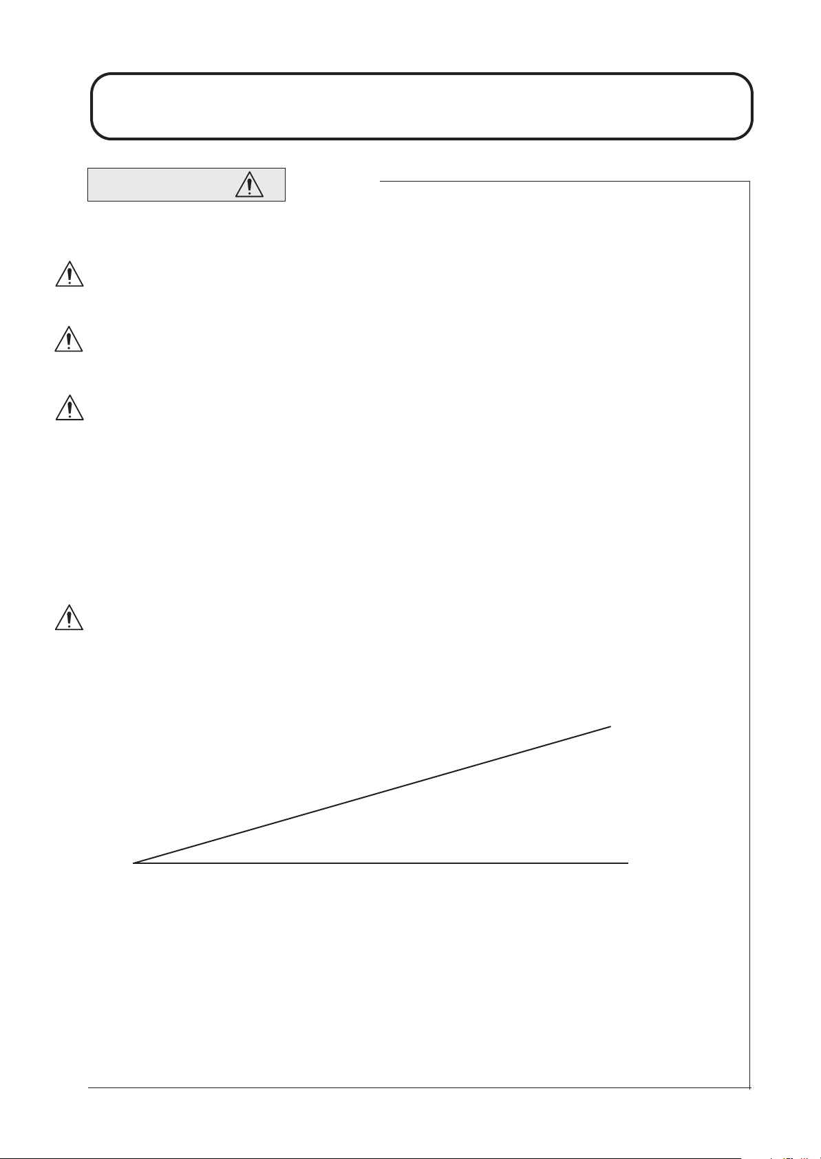
SLOPES
Do not use on a slope of more than 16 degrees. Care should be taken when using the mower on any slope
where ground conditions are such that there may be a risk of the mower rolling over. The requirements
of SI 1998 No. 2306 “Provision and Use of Work Equipment Regulations” should be considered.
Stability angles given are maximum figures for a machine equipped with a R.O.P.S and are for guidance
only. Particular conditions such as wet grass or uneven ground may not permit safe operation on the
slope limits stated.
Remember there is no such thing as a "safe" slope. Travel on grass slopes requires particular care. To
guard against overturning or loss of traction when travelling or mowing on a slope:
- Exercise extreme care when changing direction on a slope.
- Do not stop or start suddenly.
- Engage drive slowly.
- Keep machine speed low.
- Avoid tight turns.
- Stay alert for humps, hollows and other hidden hazards.
- Keep away from sharp inclines and steep drops.
- A thorough risk assessment should be carried out by a competent
person before travelling or mowing on a slope.
Never park on a slope.
OPERATION Continued.
3DA176
16 Degree slope
Ground level
111-1033TH051006
SAFETY PRECAUTIONS
OPERATION Continued.
Watch out for traffic when crossing or near roadways.
Use extreme caution when reversing.
Disengage the cutterhead drive system before crossing surfaces other than grass.
When using the machine, never direct discharge of material towards bystanders or allow anyone near
the machine while in operation.
Never operate the mower with defective guards, shields or without safety protective devices in place
and in good working order.
Do not change the engine governor settings or overspeed the engine. Operating an engine at excessive
speed may increase the risk of personal injury.
Before leaving the operator's position:
- Disengage the drive to the cutterheads.
- Lift cutterheads to the transport position and securely lock the safety latches
or alternatively lower cutterheads to the ground.
- Ensure the transmission is in neutral and engage the parking brake.
- Stop the engine and remove the ignition key.
Engage the parking brake, disengage the drive to the cutterheads, stop the engine and remove ignition key :
- Before releasing blockages.
- Before checking, cleaning or working on the mower.
- After striking a foreign object. Inspect the mower for damage and make
repairs before restarting and operating the equipment.
- If the machine starts to vibrate abnormally ( check immediately ).
- Before refuelling.
- Before making cutterhead adjustments.
Disengage the drive to the cutterheads when transporting or not in use.
Reduce the throttle setting during engine run - out.
Never work on the mower when the engine is running.
Always keep feet and hands well away from the cutting cylinders when making adjustments.
Never operate the mower without first checking that the operator platform is securely latched.
Always wear the seat belt when the folding R.O.P.S is in its vertical operating position.
Never wear the seat belt when the folding R.O.P.S is NOT in its vertical operating position.
Pay particular attention when operating due to the additional weight towards the front of the machine.
1.9
1.9

111-1033TH051006
SAFETY PRECAUTIONS
HANDLING AND STORAGE OF FLUIDS
Hydraulic Oil
- Avoid contact with eyes and prolonged contact with skin.
- Protective goggles should be worn when pouring.
- Use of gloves or barrier cream is recommended.
- Wash hands thoroughly after contact.
- Store under cover, away from heat and sources of ignition.
Diesel Oil
- Avoid skin and eye contact.
- Wear impervious gloves when regular contact is likely and goggles when there is risk of splashing.
- Wash hands thoroughly after contact.
- Store in a cool dry well ventilated place away from heat and sources of ignition, in vessels specifically designed for storing fuel oils.
Lubricating Oil
- Avoid skin and eye contact.
- Wear impervious gloves when regular contact is likely and goggles when there is risk of splashing.
- Wash hands thoroughly after contact.
- Store in a cool dry well ventilated place away from heat and sources of ignition.
Anti- Freeze
- Keep away from heat, sparks, and flames.
- Avoid skin and eye contact and breathing vapours.
- Store in a closed container in a cool dry well ventilated area.
1.10
1.10

111-1033TH051006
SAFETY PRECAUTIONS
MAINTENANCE AND STORAGE
Take care when rotating a cutting cylinder as this can cause other cylinders to rotate.
When the machine is to be parked, stored or left unattended, lift the cutterheads to the transport position
and engage the safety locks or lower the cutterheads to the ground.
Keep all nuts, bolts, and screws tight to be sure the equipment is in safe working condition.
Allow the engine to cool before storing in any enclosure.
To reduce the risk of fire, keep the engine, silencer, fuel tank and battery compartment free of grass, leaves
or excessive grease.
Frequently check fuel lines and fittings for cracks or leaks and replace if necessary.
Replace worn or damaged parts for safety.
Ensure that all safety decals are properly secured and in good condition.
If the fuel tank has to be drained, this should be done outdoors.
Be careful during adjustment of the machine to prevent entrapment of the fingers between moving blades
and fixed parts of the machine.
Never attempt to disconnect any part of the hydraulic system before de-pressurisation. This may be
achieved by lowering all cutterheads to the ground, stopping the engine and removing the ignition key.
Avoid skin or eye contact with hydraulic or diesel fluids. Wear protective clothing.
Leaking fluids under pressure can penetrate the skin or eyes, causing serious injury.
Always use a piece of cardboard or paper when searching for leaks.
Health and Safety at Work Act:
In accordance with section 6 of the Health and Safety at Work Act 1974, the Reelmaster®® 3220-D and
3240-D Mowers have been designed and constructed so that, in so far as is reasonably practical, they will
not endanger the safety and health of those working with them. This is, however, subject to the machine
being properly used and maintained according to the conditions stated in this manual and elsewhere,
which have been found necessary as a result of the research and testing of The Toro Company.
1.11
1.11
111-1033TH051006
SAFETY PRECAUTIONS
DECALS
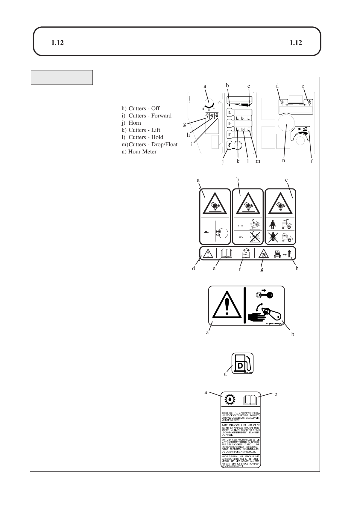
Decal - Control Panel Part No: 924898 (A)
Location: Control Panel.
a) Ignition Switch
b) Engine Speed - Slow
c) Engine Speed - Fast
d) Parking Brake - Engage
e) Parking Brake - Disengage
f) Weight Transfer - Control
g) Cutters - Reverse
Decal - Inclines Part No: 111-0936 (A)
Location: Centre Platform.
a) Warning - Travel slowly when turning and on slopes
b) Warning - Maximum Slope without ROPS
c) Warning - Seat belt must be worn with a ROPS fitted.
d) Caution
e) Read Operators Manual
f) Stop engine/Remove ignition key before servicing or
maintenance
g) Beware of flying objects
h) Keep Bystanders Clear
Decal - Danger Latch Part No: 70-13-077
Location: LH / RH / Centre Arms
a) Caution
b) Stop engine/Remove ignition key before releasing or
operating safety latches.
Decal - Diesel Part No: 70-13-07
Location: Fuel Tank
a) Diesel fuel only
Decal - Transmission Oil Part No: 70-13-071
Location: Oil Filler Bracket Mounted Behind Fuel tank.
a) Transmission Oil
b) Read and understand the Operators Manual.
IMPOR T ANT / WICHTIG / BELANGRIJK
BEFORE USE : FILL MACHINEWITH RECOM-
MENDED OILTO CORRECTLEVEL. FAILURE TO
DOSOWILL CAUSE SERIOUS DAMAGE AND IN-
VALIDATE WARRANTY .
AVANT L'UTILISA TION : IL EST IMPERATIF DE
REMPLIR LA TONDEUSE AVEC UNE HUILE
SPECIFIEE AUNIVEAU EXACT POUR NE PAS
L'ENDOMMAGER SERIEUSEMENT ET ANNULER
LAGARANTIE.
VOR DEM GEBRAUCH: F ÜLLEN SIE DIE
MASCHINE MITEMPFOHLENEM ÖL NACH,BIS
AUF DEN RICHTIGEN ST AND. DIE
NICHTBEACHTUNG DIESER INSTRUKTIONEN
KANN ZU ERNSTHAFTEN SCHADEN F ÜHREN
UNDDABEI WIRD DIE GARANTIE UNGÜLTIG.
VOOR GEBRUIK: VUL MACHINE MET
VORRGESCHREVEN OLIE TOT HET JUISTE
NIVEAU. HET NIET VOLGEN VAN DEZE
INSTRUKTIE LEIDT TOT ERNSTIGE SCHADE EN
VER VA LVANDE GARANTIE.
1.12
1.12
a
b
c
d
e
f
g
h
i
jkl
m
h) Cutters - Off
i) Cutters - Forward
j) Horn
k) Cutters - Lift
l) Cutters - Hold
m)Cutters - Drop/Float
n) Hour Meter
a
b
c
de
f
g
h
a
b
a
a
b
n
924898(REV. 0 )
III
O
I
II
P
P
kg
111-0936 (A)
111-1033TH051006
SAFETY PRECAUTIONS
DECALS Continued.
HEIZKORPERDECKELENTFERNEN ERST WENN DER MOTORKUHLIST.
ONLY REMOVE RADIATORCAP WHEN ENGINE IS COOL.
VERWIJDERDE RADIATORDOPPASNADAT DE MOTORISAFGEKOELD.
IL FAUTTOUJOURSATTENDRE LE REFROIDISSEMENTDUMOTEUR
AVANTDE RETIRER LE BOUCHONDU RADIATEUR.
70-13-073 REV (.0.)
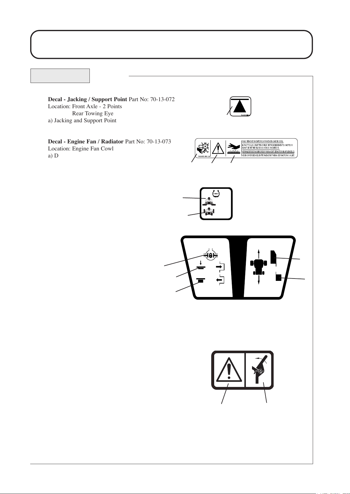
Decal - Jacking / Support Point Part No: 70-13-072
Location: Front Axle - 2 Points
Rear Towing Eye
a) Jacking and Support Point
Decal - Engine Fan / Radiator Part No: 70-13-073
Location: Engine Fan Cowl
a) Danger of Severing Fingers
b) Caution
c) Warning - Hot Surfaces
Decal - Tyre Pressure Part No. 950832 (2)
Location: LH/RH Chassis - 4 Places
a) Mowing
b) Road Travel
Decal - Diff Lock / Control Pedal Part No: 924812
Location: Centre Platform.
a) Differential Lock
b) Depress to engage Diff-lock
c) Release to Dis-engage Diff-lock
d) Forward Speed & Directional Control
e) Reverse Speed & Directional Control
Decal - Warning Crush Hazard
Part No. 111-0773(A)
A = Safety Alert - Be aware to the possibility of injury
B = Crushing of fingers. Force applied from side.
950832 Rev.2
0.7 BAR
10 PSI
1.4 BAR
20 PSI
1.13
1.13
a
a
b
c
a
b
924812 REV.(0)
a
b
c
d
e
a
b
111-0773 Rev A
111-1033TH051006
SAFETY PRECAUTIONS
DECALS Continued.
Decal - Serial Number
Location: Rear Bulkhead
Decal - Prevent Platform
Damage
Part No. 924828
Location : Platform, Seatwell.
Decal - Warning Platform Latch
Part No. 924868
Location: Next to Platform Latch
Warning - Prevent Accidents: Ensure platform is correctly seated and the latch is
fully locked before operating the machine.
Decal - Maintenance
Part No. 924882 (2)
Location: Underside of Engine Cover next
to Latch.
Decal - Noise
Part No. 922854
Location: Base of Seat on GRP
1.14
1.14
RM3240-D REELMASTER
:2800 kW:26.1
RPM
kg:1025
Code Serial No:
650D
270000001
105
PREVENT PLATFORM DAMAGE !
ENGAGE PARKING BRAKE AND
DROP CUTTERHEADS BEFORE
RAISING/LOWERING PLATFORM.
POUR EVITER DES DOMMAGES
METTRE LE FREIN DE PARKING ET POSER
LES TETES DE COUPES AVANT DE
BOUGER LA PLATE-FORME.
..
SCHADEN VERMEIDEN
FESTSETZEN UND DIE SCHNEIDEINHEITEN
HERUNTERLASSEN BEVOR DIE SITZPLATTFORM GEKIPPT WIRD.
VOORKOM BESCHADIGING!
MACHINE OP HANDREM EN LAAT DE
KOOIEN ZAKKEN, VOORDAT HET
BEDIENINGS PLATFORM NAAR VOREN
GEKANTELD OF TERUG GEPLAATST
WORDT.
dB
- PARKBREMSE
ZET
924828 REV.0.
924868 REV .0
2005
,
DAILY MAINTENANCE DAILY MAINTENANCE
FUEL LEVEL
ENGINE OIL
FUEL
EF
D
TYRES
FASTENERS
AIR CLEANER
DAILY 50 HOURS (WEEKLY)DAILY (IF FITTED)
50 HOURS MAINTENANCE
CLEAN AND INSPECT THE MACHINE.
WHEEL NUT TORQUE
FRONT: 200Nm
REAR: 54Nm
GREASE POINTS
SEAT SWITCH
HOSE LINES HYDRAULIC OIL
RADIATOR/
SCREENS
924882(Rev 1)
COOLANT LEVELCUTTERHEADS
30 - 40mm
111-1033TH051006
EC CONFORMITY INFORMATION
NOISE LEVELS
Operators Daily Personal Noise Exposure: The Toro Company has no
control over site conditions, duration of use, state of maintenance or
adjustment of the mower. All of these factors will affect the operator's
daily personal noise exposure level - L
EP,d
Under typical working conditions operators could be exposed to a daily
personal noise exposure level in excess of 85 dB (A) L
EP,d
Sound pressure level:
The sound pressure level at the operator's position is 84 dB (A)
measured in accordance with European Standard EN836.
Sound power level:
The guaranteed sound power level is 105 dB(A) measured in accordance
with EC Directive 2000/14/EC.
If hearing protection is required, ear protectors with good attenuation in
the 63 - 8000 Hz frequency range should be used.
Employers of personnel using this machine are advised to read the 'Noise
at Work Regulations' as the operator's daily personal exposure level could
be above the 'First Action Level'.
1.15
1.15
Wear Hearing
Protection
VIBRATION LEVELS
Operators Daily Personal Vibration Exposure: HAYTER LIMITED have
no control over site conditions, duration of use, state of maintenance or adjustment of the mover. All of these factors will affect the operator’s daily
personal vibration exposure level.
Under certain working conditions the operator may be exposed to vibration
levels above those stated.
RM3240-D REELMASTER
:2800 kW:26.1
RPM
kg:1025
Code Serial No:
650D
270000001
2005
105
dB
111-1033TH051006
EC CONFORMITY INFORMATION
EC DECLARATION OF CONFORMITY
1.16
1.16
101dB(A)
105dB(A)
EC DECLARATION OF CONFORMITY
Manufact ured for The Toro Company
By: HAYTE R LIMITED,
Spellbrook, Bishop’s Stortford, Herts. CM23 4BU. ENGLAND
declare tha t the lawnmow er :
Model name:
Type:
Model No:
Cutting width:
Speed of rotation of the cu tting
device:
Engine manufacturer:
Speedofrotationofengine:
Complies with the provisions of Directive: 98/37/EC Essentia l Health & Safety Requirements Relating to the Design &
Construction of Machinery and Safety Components, as amended and the regulations transposed into national law.
RM3220-D
Ride-on Cylinder
CODE 650D
212cm
1050 rpm
Kubota
2850 rpm
RM3240-D
Ride-on Cylinder
CODE 651D
212cm
1050 rpm
Kubota
2850 rpm
Also Directive 79/622/EEC Roll Over Protection Structures, as amended and the regulation s transposed into national law.
Also Directive 89/336/EEC Electromagnetic Compatibili ty, as amended and the regulations transposed into national law.
Also Directi ve 2000/14/EC Noise emission in the enviro nm ent by equipment for use outdoors and the regulations transposed into
national law.
Procedure applied for the conformity assessment: ANNEX VI, procedure 1.
Notified Body: Sound Research Laboratories Ltd. Holbrook House, Lit tle Waldingfield,
Sudbury , Suffolk. CO10 0TH. ENGLAND
Notified body identification No: 1088
Measured sound power level :
Guaranteed sound power level:
Complies with harmonized standards: EN 292, EN 836 and EN ISO 14982
Signed
S.A Maryniak
(Technical Director)
101dB(A)
105dB(A)
Date: 15.12.05
Declaration done and technical do cumentation k ept at:
HAYTER LIMITED
Spellbrook, Bishop’s Stortford,
Herts. CM23 4BU ENGLAND
VIBRATION INFORMATION
The vibration level at the operator contact positions, measured in accordance with European Standard EN 836
CODE 650D Steering Whee l Does not exceed 2.5ms-2Seat Does not exceed 0.5ms
CODE 651D Steering Whee l Does not exceed 2.5ms-2Seat Does not exceed 0.5ms
-2
-2

111-1033TH051006
INTRODUCTION
The Toro Reelmaster® 3220-D is a diesel engine powered self propelled machine with hydraulic systems for ground drive, cutterhead drives and steering. The machine operates in two wheel drive.
The 3240-D machine also is a diesel engine powered self propelled machine and operates in two wheel
drive with automatic four wheel drive on demand. A differential lock function may be selected. The
transmission system is converted automatically to engage drive to all 4 wheels when the machine speed
decreases as a result of front wheel traction slip. 2WD is automatically re-engaged when traction slip is
reduced.
The Toro Reelmaster® 3220-D and 3240-D are precision built machines designed solely for cutting grass
and similar low lying ground vegetation within the limitations stated in this manual. Use in any other
way is considered as contrary to the intended use. Compliance with and strict adherence to the conditions of operation, service and repair as specified in this Operators Manual also constitute essential elements of the intended use. The way in which these machines are operated and maintained will have a
profound effect on its performance and reliability.
This manual contains advice on the Toro Reelmaster® 3220-D and 3240-D which should be operated, serviced and repaired only by persons who are familiar with their particular characteristics and who are
acquainted with the relevant safety procedures.
The safety precautions listed herein and all other generally recognised regulations on safety and all road
traffic regulations must be observed at all times.
Any arbitrary modifications carried out to these machines may relieve The Toro Company of liability for
any resulting damage or injury.
In the pursuit of continuous product development The Toro Company reserves the right to alter specifications without notice.
Cutterhead Variants: The Toro Reelmaster® 3220-D and 3240-D can be fitted with a range of cutterhead configurations and optional extras:
Optional Extras:
Beacon Kit - Amber flashing warning light.
Lighting Kit - Complies with EC traffic regulations.
R.O.P.S. Cab - Full weather protection and roll - over protection.
Note: with a R.O.P.S. Cab fitted stability angle will decrease on both the RM3220-D and
RM3240-D, due to the higher centre of gravity of the machine.
When fitting optional extra kits to the mower be sure to fix the serial number decal supplied with the
kit to the rear bulkhead underneath the engine cover. This will help the Toro spare parts department to
supply the correct spare parts throughout the service life of the mower.
Left and Right: Throughout this manual the terms 'Left' and 'Right' refer to the machine when looking
in the direction of forward travel.
Fixed
Heads
Cutterhead
Number of bladesCylinder diameter
MK3 Cutterhead
200mm (8")
4, 6, 8, 10.
✔
✔
Floating Heads with smooth
or grooved front rollers
254mm (10")
4, 6
✔
INTRODUCTION
1.17
1.17

111-1033TH051006
SPECIFICATIONS
ALL FIGURES ARE NOMINALLY QUOTED AT THE RATED ENGINE SPEED OF 2800 RPM
UNLESS OTHERWISE STATED.
ENGINE
Type:
Power Rating:
Capacity:
Air Cleaner:
Cooling System:
Battery:
Alternator:
Starter:
Cold Starting:
Idle Speed:
Fuel Type:
IMPORTANT: PREVENT DAMAGE - for further information regarding the engine, refer to ENGINE MANUAL .
SPECIFICATIONS
3240-D
Kubota V1505 -BB.
4 Cylinders in line.
26.1 kw (35hp) @ 2800 RPM.
DIN 70020.
1498 cc (91.4 cu in).
Clean air drawn through screened air
intake in-front of radiator via a cyclonic
air cleaner with built in pre-cleaner.
Water-Cooled.
12V. 480 Amps S.A.E.
40 Amps.
1.2 KW (1.6 hp) Electric.
Glow Plug.
1250(+50) R.P.M.
Diesel.
1.18
1.18
3220-D
Kubota V1305 -E.
4 Cylinders in line.
24.0 kw (31.1hp) @ 2800 RPM.
DIN 70020.
1335 cc (81.5 cu in).
Clean air drawn through screened air
intake in-front of radiator via a
cyclonic air cleaner with built in
pre-cleaner.
Water-Cooled.
12V. 480 Amps S.A.E.
40 Amps.
1.2 KW (1.6 hp) Electric.
Glow Plug.
1250 (+50) R.P.M
Diesel.

111-1033TH051006
SPECIFICATIONS
TRANSMISSION SYSTEM
Drive Type:
Pump:
Wheel Motors:
Differential Lock:
Drive:
Relief Valve Setting:
CUTTERHEAD DRIVE SYSTEM
Drive Type:
Pump:
Delivery Rate:
Cutterhead Motors:
Control:
Relief Valve Setting:
Hydraulic.
Variable displacement hydraulic piston pump with integral charge
pump and pedal control.
Front Axle - Radial piston, fixed displacement, with integral disc
brake (pressure released).
3240-D Only: Rear Axle - Gear motor, fixed displacement.
Electro - hydraulic control valve with pedal control.
2WD (front axle) with differential lock (selectable).
3240-D Only: Automatic 4WD on demand (forward & reverse).
3220-D: Main service relief 250 bar (3265 psi) differential.
3240-D: Main service relief 300 bar (4350 psi) differential.
Charge pressure relief 18.5 bar (268 psi) differential.
Hydraulic.
Hydraulic gear type.
31 Litres per minute (8.2 UK gallons per minute).
Hydraulic gear type, reversible, pressure balanced with integral
differential pressure sensing relief check valve. Direct drive.
Electro-hydraulic.
Automatic diverter valve safety cut-off.
250 bar (3625 psi) differential.
1.19
1.19

111-1033TH051006
SPECIFICATIONS
CUTTERHEAD LIFT SYSTEM AND STEERING
Drive Type:
Pump:
Delivery Rate:
Steering:
Cutterhead Lift Control:
Relief Valve:
Weight Transfer:
HYDRAULIC SYSTEM
Hydraulic Oil Type:
Capacity:
Cooling:
Suction Line Filtration:
Return line Filtration:
Transmission Filtration:
Maximum Oil Contamination Level:
Maximum Oil Temperature:
Hydraulic.
Hydraulic gear pump with integral relief valve.
11 Litres per minute (2.9 UK gallons per minute).
Power beyond hydrostatic steering valve with priority flow to
steering and auxiliary flow to cutterhead lift system. Manual
emergency steering.
Mechanical-hydraulic.
105 bar (1522 psi).
Variable hydraulic applied weight transfer acting on all
cutterheads.
Refer - RECOMMENDED LUBRICANTS
AND HYDRAULIC FLUIDS.
40 Litres (8.8 UK gallons).
Forced air finned tube oil cooler.
125 micron no bypass mesh filter.
10 micron with 2 bar (29 psi) bypass check valve.
10 micron no bypass pressure filter.
ISO Code 18/13 or better (ISO 4406)
1300 - 2500 Particles/ml<15μ
40 - 80 Particles/ml>15μ
95
0
C (2030F)
1.20
1.20

111-1033TH051006
SPECIFICATIONS
Wheel Nut Torque Setting: Front axle 200Nm (148 Ibf.ft).
Rear axle 54Nm (40 Ibf.ft).
Service Brakes: Closed loop hydrostatic service braking operating on drive wheels only.
Parking Brake: Lever operated oil immersed disc brakes on front wheels only. Pressurised hydraulic oil
release with mechanical override for emergency towing purposes.
Ground Clearance: 180mm(7.1") at 13mm(.5") cut height and with cutterheads raised.
Steering: Hydrostatic rear wheel steering, emergency manual steering.
Features: Tilting operator platform.
Lockable engine cover.
Adjustable suspension seat with folding arms.
Adjustable steering column.
Cutterhead parking latches with safety locks.
Backlapping facility.
Differential lock ( selectable ).
Engine coolant and hydraulic oil overheat audible warning (horn).
Variable cutterhead weight transfer/traction assistance.
2WD (3240-D Only: 4WD on demand (forward & reverse)).
Hydraulic oil filter blocked telltales on control panel.
Safety Features: Neutral start interlock on transmission pump, parking brake and
cutterhead drive switch.
Operator presence control (seat switch).
2 Post folding R.O.P.S designed and tested to European Directive 79/622/EEC.
VEHICLE SPECIFICATIONS
Travel Speed:
0-22 km/hr (0-14 mph) forward.
0-11 km/hr (0-7 mph) reverse.
Tyre s Tyre Type
Front axle
Rear axle
0.7 bar
(10 psi )
0.7 bar
(10 psi).
1.4 bar
(20 psi)
1.4 bar
(20 psi)
Recommended Tyre Pressures
Turf Conditions
Max Pressure
Road Conditions
26 x 12 - 12 4 ply
Trelleborg turf pattern.
18 x 9.5 - 8 6 ply
Dico turf pattern.
1.7 bar
(25 psi)
1.7 bar
(25 psi)
1.21
1.21

111-1033TH051006
SPECIFICATIONS
Automotive padded steering wheel.
Electrical switch (forward - off - reverse).
Hand operated lever.
Hand operated lever.
Forward and reverse foot pedal.
Key start, shut - off and engine preheat.
Foot pedal.
Hand operated lever.
Button switch.
Hand wheel.
Engine oil pressure.
Battery charge.
Engine coolant temperature.
Hydraulic transmission oil temperature.
Digital hour meter.
Fuel level.
Hydraulic oil level sight glass.
Engine pre-heat.
Hydraulic return filter blocked.
Hydraulic transmission filter blocked.
Cutterhead drive switch off.
Parking brake engaged.
Transmission neutral.
Steering:
Cylinder Drive:
Engine Speed:
Parking Brake:
Forward and Reverse:
Ignition:
Differential Lock:
Cutterhead Position:
Horn:
Weight Transfer:
OPERATOR CONTROLS
INSTRUMENTATION
Warning Lights:
Gauges:
Indicator Lights:
1.22
1.22

1.23
SPECIFICATIONS
WEIGHT AND DIMENSIONS
1.23
Wheel Base:
Working Width:
Cutting Width:
Transport Width:
Overall Length:
Overall Height:
Working Weight:
1440 mm (56.7").
2300 mm (90.6").
2120 mm (83.5").
1575 mm (58") at 13mm (.5") height of cut.
2690 mm (106").
1770 mm (69.7") with R.O.P.S folded.
2424 mm (95.4") with R.O.P.S in its vertical operating position.
Including 2 post R.O.P.S, 8 inch 6 blade cutterheads and full tank of
fuel. It excludes the operator and any other options.
1266 kg (2791 Ib) LT322 only
1317 kg (2903 Ib) LT324 only
RECOMMENDED LUBRICANTS AND HYDRAULIC FLUIDS
Grease Points: A good quality medium grease.
Engine: Refer - ENGINE OPERATORS MANUAL.
Hydraulic System:
Ambient Temperature Range
O
0 - 30 C (32 - 86 F)
I S O viscosity grade
46 hydraulic oil.
O
15 - 40 C (59 - 104 F)
O
I S O viscosity grade
68 hydraulic oil.
Should you be in any doubt please contact your Toro dealer. Using incorrect grades will cause
premature wear of hydraulic components and invalidate warranty.
O
111-1033TH051006

111-1033TH051006
SPECIFICATIONS
CUTTERHEADS
Cutting Width:
Cylinder Diameter:
Cylinder Speed:
Height of Cut:
Number of Blades:
Smooth Rear Roller:
Smooth Front Roller:
Grooved Front Roller:
Configuration:
MK3 200mm Cutterhead
762 mm (30").
200 mm (8").
1050 rpm approx.
12mm(.5") - 80mm (3").
4, 6, 8, 10
Standard.
Optional.
Optional.
Fixed / Floating.
MK3 254mm Cutterhead
762 mm (30").
254 mm (10").
1050 rpm approx.
12 - 80 mm.
4, 6
Standard.
-
-
Fixed
1.24
1.24

111-1033TH051006
OPERATING THE MOWER
OPERATOR PRESENCE CONTROLS
Cutting Cylinder Drive Lockout: Drive to the cutting cylinders is only possible when the operator is
seated. If the operator raises off the seat for a period of more than one second, a switch is activated and
drive to the cutting cylinders is automatically disengaged. To re-engage drive to the cutting cylinders, the
operator must return to the seat, then operate the cutterhead drive switch to the ‘OFF’ position before
moving it back to the ‘ON’ position. If the operator rises off the seat for a brief moment during normal
work, drive to the cutting cylinders is not affected.
The engine can only be started with the cutterhead drive switch in the ‘OFF’ position.
Engine Start Lockout: The engine can only be started when the forward/reverse travel pedal is released
to the 'NEUTRAL' position, the cutterhead drive switch is in the ‘OFF’ position and the parking brake is
engaged. When these circumstances are satisfied, switches are activated permitting the engine to be started.
Engine Run Interlock: Once the engine is started the operator must be seated before the parking brake is
released for the engine to continue to run.
Note: The engine will cut out if the operator leaves the seat without engaging the parking brake.
WARNING: PREVENT ACCIDENTS - Do not operate the Reelmaster®® mower if the operator
presence controls are defective in any way. ALWAYS replace faulty parts and check that they function correctly before operating the mower.
SAFETY NOTICE
WARNING: PREVENT ACCIDENTS - Before operating the mower it is essential that;
- The operator reads and understands this manual.
- The operator platform latching mechanism is fully engaged and in good working order, refer Operator Platform Latching Mechanism.
- The daily maintenance checks have been properly carried out and the mower is in good working
order.
- The operator should wear safety clothing and eye protection. Failure to do so could result in risk to
health and safety.
- The area where the equipment is to be used is inspected and all objects which may be thrown by the
machine are removed.
Operate safely on slopes;
It is essential to follow safe working practices when working on slopes. In order to avoid potentially
hazardous situations, it is essential that the operator understands and observes the relevant safety
precautions listed in this manual, refer - ‘SAFETY PRECAUTIONS’.
This machine is fitted with a R.O.P.S as standard to increase operator safety in the event of the
machine rolling over.
The R.O.P.S frame may be folded down to allow access into area of restricted height.
While the R.O.P.S is folded down it does not provide any protection in the event of a roll over and
should not be considered as a Roll Over Protective structure.
1.25
1.25
111-1033TH051006
OPERATING THE MOWER
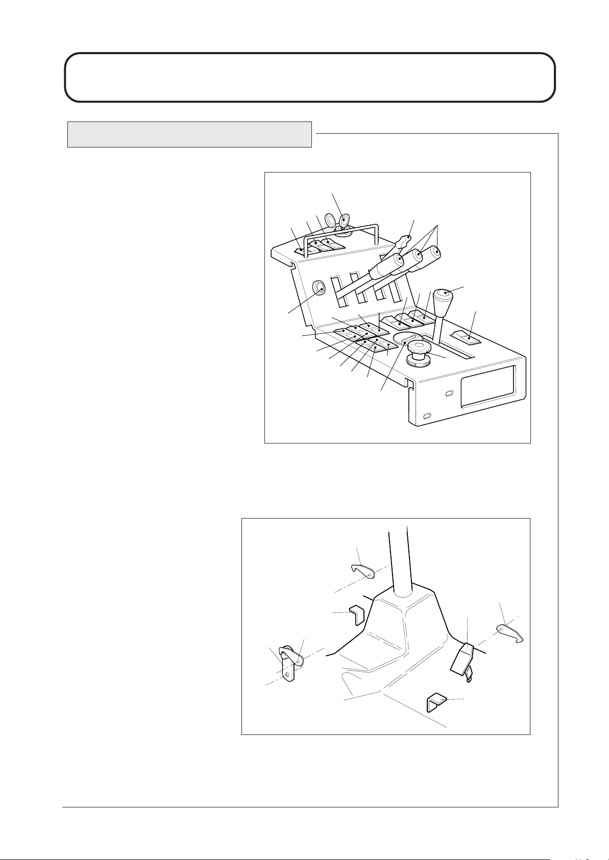
1.
2.
3.
4.
5.
6.
7.
8.
9.
10.
11.
12.
13.
14.
15.
16.
17.
18.
19.
20.
21.
22.
23.
24.
25.
26.
27.
28.
29.
30.
31.
Parking brake lever.
Lighting switch
(supplied with lighting kit).
Warning beacon switch
(supplied with beacon kit).
Hazard warning switch
(supplied with lighting kit).
Cutterhead position controls.
Throttle control lever.
Ignition key.
Cutterhead drive switch.
Dip beam / main beam light switch
(supplied with lighting kit).
Direction indicator switch
(supplied with lighting kit).
Horn button.
Transmission oil filter indicator.
Oil pressure indicator.
Transmission temperature indicator.
Return oil filter indicator.
Battery warning indicator.
Engine temperature warning
indicator.
Glow plug indicator.
Cutterhead drive off indicator.
Parking brake indicator.
Transmission neutral indicator.
Weight transfer control.
Wash / wipe switch
(supplied with cab kit).
Hour Meter
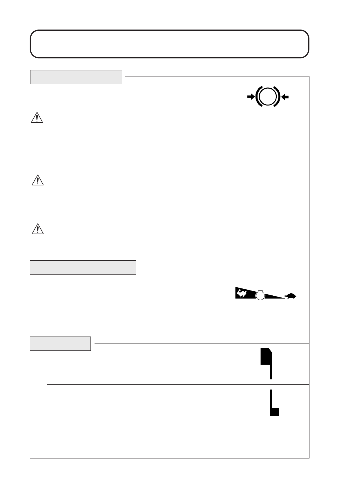
Left hand cutterhead safety latch.
Right hand cutterhead safety latch.
Centre cutterhead transport latch.
Reverse travel pedal.
Forward travel pedal.
Differential lock pedal.
Centre cutterhead safety latch.
4A924A02 (1)
1
2
5
6
10
9
4
7
8
11
14
13
12
15
16
18
19
20
21
17
22
3
23
24
HOURS
QUARTZ
CURTIS
1
10
1D924S04A (1)
31
27
25
29
26
28
30
IDENTIFICATION OF CONTROLS
1.26
1.26
111-1033TH051006
OPERATING THE MOWER
BRAKING SYSTEM
Parking brake : Move the parking brake lever to its rear position to engage the
parking brake. Do not operate the mower with the parking brake engaged.
WARNING : PREVENT ACCIDENTS - The parking brake operates on the front wheels only. Do not
park the mower on a slope.
Service brakes : Service braking is achieved by the hydraulic transmission system. When the forward or
reverse travel pedals are released or the engine speed reduced, service braking becomes effective and travel speed is automatically reduced. To increase the braking effect, push the transmission pedal into the neutral position. Service braking is effective on the front wheels only.
WARNING : PREVENT ACCIDENTS - The service braking system will not hold the mower at a standstill. ALWAYS ensure the parking brake is engaged to park the mower at a standstill.
Emergency braking : In the event of service brake failure, turn the ignition off to bring the mower to a
standstill.
WARNING: PREVENT ACCIDENTS - Take care when using the emergency braking. Remain
seated and hold on to the steering wheel to prevent ejection from the mower caused by the front
wheel brakes being applied suddenly when travelling.
THROTTLE CONTROL
Operate the throttle control in a forward direction to increase the engine speed.
Operate the throttle control in a rearward direction to reduce engine speed.
Note that the engine speed dictates the speed of the other functions, i.e. travel, cutting cylinder, position controls.
TRAVEL
Forward travel: Depress the forward travel pedal to increase forward travel
speed. Release the pedal to reduce speed.
Reverse travel: Depress the reverse travel pedal to increase reverse travel speed.
Release the pedal to reduce speed.
Stop (Neutral): Release the forward or reverse travel pedal.
1.27
1.27
Parking brake engaged
SlowFast
Engine Speed
P
 Loading...