

Page 1
Preface
The purpose of this publication is to provide the service
technician with information for troubleshooting, testing
and repair of major systems and components on the
ProCore 648.
REFER TO THE OPERATOR’S MANUALS FOR OPERATING, MAINTENANCE AND ADJUSTMENT
INSTRUCTIONS. Space is provided in Chapter 2 of this
book to insert the Operator’s Manuals and Parts Catalogs for your machine. Replacement Operator’s Manuals and Parts Catalogs are available on the internet at
www.toro.com.
The Toro Company reserves the right to change product
specifications or this publication without notice.
Part No. 04129SL (Rev. C)
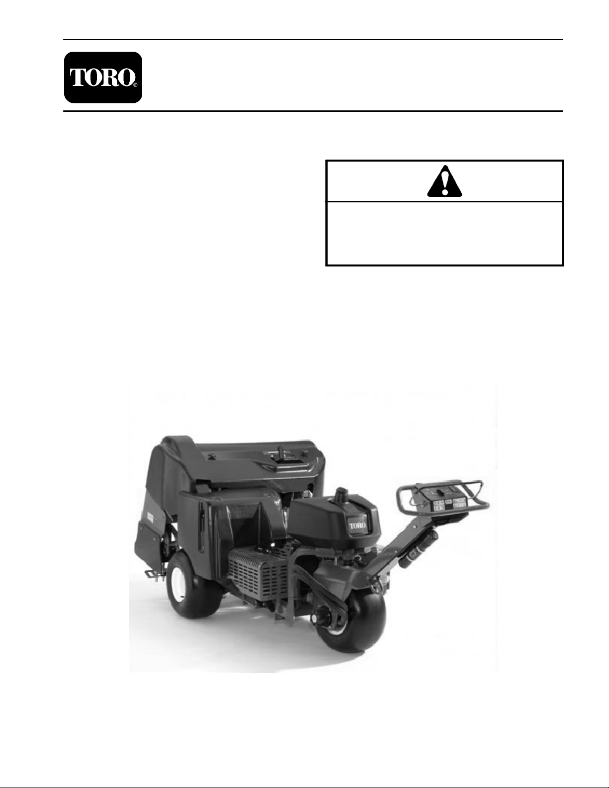
Service Manual
ProCoreR648
This safety symbol means DANGER, WARNING,
or CAUTION, PERSONAL SAFETY INSTRUCTION. When you see this symbol, carefully read
the instructions that follow. Failure to obey the
instructions may result in personal injury.
NOTE: A NOTE will give general information about the
correct operation, maintenance, service, testing or repair of the machine.
IMPORTANT: The IMPORTANT notice will give im portant instructions which must be followed to prevent damage to systems or components on the
machine.
E The Toro Company -- 2004, 2006, 2009
Page 2

This page is intentionally blank.
ProCore 648
Page 3

Table Of Contents
Chapter 1 – Safety
Safety Instructions . . . . . . . . . . . . . . . . . . . . . . . . . . 1 – 2
Jacking Instructions
Safety and Instruction Decals
Chapter 2 – Product Records and Maintenance
Product Records . . . . . . . . . . . . . . . . . . . . . . . . . . . 2 – 1
Maintenance
Equivalents and Conversions
Torque Specifications
Chapter 3 – Kohler Engine
Introduction . . . . . . . . . . . . . . . . . . . . . . . . . . . . . . . . 3 – 2
Specifications
General Information
Adjustments
Service and Repairs
KOHLER ENGINE SERVICE MANUAL
Chapter 4 – Hydraulic System
Specifications . . . . . . . . . . . . . . . . . . . . . . . . . . . . . . 4 – 2
General Information
Hydraulic Schematic
Hydraulic Flow Diagrams
Special Tools
Troubleshooting
Testing
Service and Repairs
HYDRO–GEAR BDP–10A/16A/21L HYDROSTATIC
PUMPS SERVICE AND REPAIR MANUAL
SAUER DANFOSS GROUP 2 GEAR PUMPS AND
MOTORS SERVICE MANUAL
SAUER DANFOSS OMEW HYDRAULIC MOTOR
SERVICE MANUAL
. . . . . . . . . . . . . . . . . . . . . . . . . . . . . . . 2 – 1
. . . . . . . . . . . . . . . . . . . . . . . . . . . . . . . 3 – 5
. . . . . . . . . . . . . . . . . . . . . . . . . . . . . . . . . . . 4 – 17
. . . . . . . . . . . . . . . . . . . . . . . . . 1 – 4
. . . . . . . . . . . . . . . . 1 – 5
. . . . . . . . . . . . . . . . 2 – 2
. . . . . . . . . . . . . . . . . . . . . . . 2 – 3
. . . . . . . . . . . . . . . . . . . . . . . . . . . . . . 3 – 3
. . . . . . . . . . . . . . . . . . . . . . . . 3 – 4
. . . . . . . . . . . . . . . . . . . . . . . . 3 – 7
. . . . . . . . . . . . . . . . . . . . . . . . 4 – 4
. . . . . . . . . . . . . . . . . . . . . . . . 4 – 7
. . . . . . . . . . . . . . . . . . . . 4 – 8
. . . . . . . . . . . . . . . . . . . . . . . . . . . . . 4 – 12
. . . . . . . . . . . . . . . . . . . . . . . . . . . 4 – 14
. . . . . . . . . . . . . . . . . . . . . . . 4 – 30
Chapter 5 – Electrical System
Electrical Diagrams . . . . . . . . . . . . . . . . . . . . . . . . . 5 – 1
Circuit Operation
Special Tools
Troubleshooting
Electrical System Quick Checks
Component Testing
Service and Repairs
Chapter 6 – Chassis
Specifications . . . . . . . . . . . . . . . . . . . . . . . . . . . . . . 6 – 2
Special Tools
Service and Repairs
Chapter 7 – Coring Head
General Information . . . . . . . . . . . . . . . . . . . . . . . . 7 – 2
Service and Repairs
Chapter 8 – Electrical Diagrams
Electrical Schematic . . . . . . . . . . . . . . . . . . . . . . . . 8 – 3
Electrical Circuit Drawings
Wire Harness Drawings
. . . . . . . . . . . . . . . . . . . . . . . . . . . 5 – 2
. . . . . . . . . . . . . . . . . . . . . . . . . . . . . . 5 – 7
. . . . . . . . . . . . . . . . . . . . . . . . . . . . 5 – 8
. . . . . . . . . . . . . 5 – 11
. . . . . . . . . . . . . . . . . . . . . . . . 5 – 13
. . . . . . . . . . . . . . . . . . . . . . . 5 – 28
. . . . . . . . . . . . . . . . . . . . . . . . . . . . . . 6 – 3
. . . . . . . . . . . . . . . . . . . . . . . . 6 – 4
. . . . . . . . . . . . . . . . . . . . . . . . 7 – 4
. . . . . . . . . . . . . . . . . . . 8 – 4
. . . . . . . . . . . . . . . . . . . . 8 – 11
SafetyProduct Records
and Maintenance
Kohler
Engine
System
Hydraulic
System
Electrical
ChassisCoring HeadElectrical
ProCore 648
Diagrams
Page 4

This page is intentionally blank.
ProCore 648
Page 5

Table of Contents
SAFETY INSTRUCTIONS . . . . . . . . . . . . . . . . . . . . . . 2
Before Operating . . . . . . . . . . . . . . . . . . . . . . . . . . . . 2
While Operating . . . . . . . . . . . . . . . . . . . . . . . . . . . . . 2
Maintenance and Service . . . . . . . . . . . . . . . . . . . . 3
JACKING INSTRUCTIONS . . . . . . . . . . . . . . . . . . . . . 4
SAFETY AND INSTRUCTION DECALS . . . . . . . . . . 5
Chapter 1
Safety
Safety
ProCore 648
Page 1 – 1
Safety
Page 6

Safety Instructions
The ProCore 648 is designed and tested to offer safe
service when operated and maintained properly. Although hazard control and accident prevention partially
are dependent upon the design and configuration of the
machine, these factors are also dependent upon the
awareness, concern and proper training of the personnel involved in the operation, transport, maintenance
and storage of the machine. Improper use or maintenance of the machine can result in injury or death. To reduce the potential for injury or death, comply with the
following safety instructions.
Before Operating
WARNING
To reduce the potential for injury or death,
comply with the following safety instructions.
1. Read and understand the contents of the Operator’s
Manual before starting and operating the machine. Become familiar with the controls and know how to stop the
machine and engine quickly. Additional copies of the
Operator’s Manual are available on the internet at
www.Toro.com.
2. Keep all shields, safety devices and decals in place.
If a shield, safety device or decal is defective, illegible
or damaged, repair or replace it before operating the
machine. Also tighten any loose nuts, bolts or screws to
ensure machine is in safe operating condition.
3. Assure interlock switches are adjusted correctly so
engine cannot be started unless traction lever is in NEUTRAL and coring head is DISENGAGED.
While Operating
1. Operator should be standing at the side console
when starting the engine and at the handle when operating the machine. Stay away from the coring head when
it is engaged.
2. Before starting the engine:
A. Engage the parking brake.
B. Make sure traction lever is in neutral.
4. Since gasoline is highly flammable, handle it carefully:
A. Store fuel in containers specifically designed for
this purpose.
B. Do not remove machine fuel tank cap while engine is hot or running.
C. Do not smoke while handling fuel.
D. Fill fuel tank outdoors and only to within an inch of
the top of the tank, not the filler neck. Do not overfill
the fuel tank.
E. Wipe up any spilled fuel.
5. Do not touch engine, muffler or exhaust pipe while
engine is running or soon after it is stopped. These
areas could be hot enough to cause burns.
6. Before leaving the operator’s position:
A. Ensure that traction lever is in neutral.
B. Raise coring head and wait for coring head to
stop.
3. After engine is started, release parking brake and
apply no pressure to traction lever. Machine must not
move. If movement is evident, the traction linkage is adjusted incorrectly . Shut engine off and adjust traction
linkage until machine does not move when traction lever
is released (see Operator’s Manual).
4. Do not run engine in a confined area without adequate ventilation. Exhaust fumes are hazardous and
could possibly be deadly.
Safety
Page 1 -- 2
C. Set parking brake. Stop engine and remove key
from ignition switch.
7. Anytime the machine is parked (short or long term),
install the service latch to secure the coring head in the
raised position. This eliminates the risk of the coring
head accidentally lowering to the ground.
8. Do not park on slopes unless wheels are chocked or
blocked.
Rev. C
ProCore 648
Page 7

7. Anytime the machine is parked (short or long term),
install the service latch to secure the coring head in the
raised position. This eliminates the risk of the coring
head accidentally lowering to the ground.
Maintenance and Service
8. Do not park on slopes unless wheels are chocked or
blocked.
1. Before servicing or making adjustments, position
machine on level surface, raise coring head, set parking
brake, stop engine and remove key from the ignition
switch. Install the service latch to secure the coring head
in the raised position.
2. Make sure machine is in safe operating condition by
keeping all nuts, bolts and screws tight.
3. Never store the machine or fuel container inside
where there is an open flame, such as near a water heater or furnace.
4. Make sure all hydraulic line connectors are tight and
all hydraulic hoses and lines are in good condition before applying pressure to the hydraulic system.
5. Keep body and hands away from pin hole leaks in hydraulic lines that eject high pressure hydraulic fluid. Use
cardboard or paper to find hydraulic leaks. Hydraulic
fluid escaping under pressure can penetrate skin and
cause injury. Hydraulic fluid accidentally injected into
the skin must be surgically removed within a few hours
by a doctor familiar with this form of injury or gangrene
may result.
6. Before disconnecting any hydraulic component or
performing any work on the hydraulic system, all pressure in system must be relieved. See Relieving Hydraulic System Pressure in the General Information section
of Chapter 4 – Hydraulic System.
7. If major repairs are ever needed or assistance is desired, contact an Authorized Toro Distributor.
8. Use care when checking or servicing the coring
head: wear gloves and use caution.
9. To reduce potential fire hazard, keep engine area
free of excessive grease, grass, leaves and dirt.
11. Do not overspeed the engine by changing governor
setting. To assure safety and accuracy, check maximum
engine speed with a tachometer.
12.Shut engine off before checking or adding oil to the
engine crankcase.
13.Disconnect battery before servicing the machine.
Disconnect negative battery cable first and positive battery cable last. If battery voltage is required for troubleshooting or test procedures, temporarily connect the
battery. Reconnect positive battery cable first and negative battery cable last.
14.Battery acid is poisonous and can cause burns.
Avoid contact with skin, eyes and clothing. Protect your
face, eyes and clothing when working with a battery.
15.Battery gases can explode. Keep cigarettes, sparks
and flames away from the battery.
16.At the time of manufacture, the machine conformed
to all applicable safety standards. To assure optimum
performance and continued safety certification of the
machine, use genuine Toro replacement parts and accessories. Replacement parts and accessories made
by other manufacturers may result in non-conformance
with the safety standards, and the warranty may be
voided.
17.When changing tires or performing other service,
use correct blocks, hoists and jacks. Make sure machine is parked on a solid level floor such as a concrete
floor. Prior to raising the machine, remove any attachments that may interfere with the safe and proper raising
of the machine. Always chock or block wheels. Use jack
stands or solid wood blocks to support the raised machine. If the machine is not properly supported by blocks
or jack stands, the machine may move or fall, which may
result in personal injury (see Jacking Instructions).
Safety
10.If engine must be running to perform maintenance or
make an adjustment, keep hands, feet, clothing and other parts of the body away from all moving machine parts.
Keep bystanders away.
ProCore 648
Page 1 – 3
Safety
Page 8
Jacking Instructions
CAUTION
When changing attachments, tires or performing other service, use correct blocks, hoists
and jacks. Make sure machine is parked on a
solid level surface such as a concrete floor.
Prior to raising machine, remove any attachments that may interfere with the safe and proper
raising of the machine. Always chock or
block wheels. Use jack stands or solid wood
blocks to support the raised machine. If the machine is not properly supported by blocks or
jack stands, the machine may move or fall,
which may result in personal injury.
Jacking the Front End
1. Set parking brake and chock rear tires to prevent the
machine from moving. Install service latch to secure
coring head.
IMPORTANT: To prevent wheel motor damage, DO
NOT use front wheel motor as a jacking point.
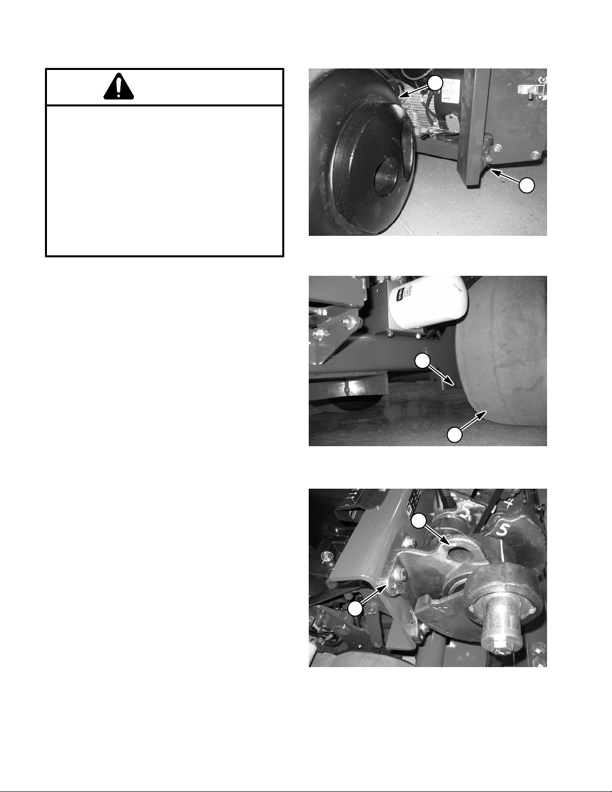
2. Position jack securely under the front of the frame
(Fig. 1).
1
Figure 1
1. Front wheel 2.
2
2
Frame jacking point
3. Jack front of machine off the ground.
4. Position jack stands or hardwood blocks under the
front of the frame to support the machine.
Jacking the Rear End
1. Chock front tire to prevent the machine from moving.
Install service latch to secure coring head.
IMPORTANT: To prevent wheel motor damage, DO
NOT use rear wheel motor as a jacking point.
2. Place jack securely under the frame plate just inside
of the rear wheel (Fig. 2).
NOTE: If available, a hoist can be used to lift the rear
of the ProCore 648. Use eyelets in coring head bearing
housings as hoist attachment points (Fig. 3).
3. Jack (or lift) rear of machine off the ground.
4. Position jack stands or hardwood blocks under the
frame to support the machine.
1
Figure 2
1. Rear wheel 2. Frame jacking point
2
1
Figure 3
1. Bearing housing 2. Lifting eyelet
Safety
Page 1 – 4
ProCore 648
Page 9

Safety and Instruction Decals
Numerous safety and instruction decals are affixed to
the ProCore 648. If any decal becomes illegible or damaged, install a new decal. Part numbers for replacement
decals are listed in your Parts Catalog. Order replacement decals from your Authorized Toro Distributor.
Safety
ProCore 648
Page 1 – 5
Safety
Page 10

This page is intentionally blank.
Safety
Page 1 – 6
ProCore 648
Page 11

Product Records and Maintenance
Table of Contents
Chapter 2
PRODUCT RECORDS . . . . . . . . . . . . . . . . . . . . . . . . . 1
MAINTENANCE . . . . . . . . . . . . . . . . . . . . . . . . . . . . . . 1
EQUIVALENTS AND CONVERSIONS . . . . . . . . . . . 2
Decimal and Millimeter Equivalents . . . . . . . . . . . . 2
U.S. to Metric Conversions . . . . . . . . . . . . . . . . . . . 2
TORQUE SPECIFICATIONS . . . . . . . . . . . . . . . . . . . 3
Fastener Identification . . . . . . . . . . . . . . . . . . . . . . . 3
Product Records
Insert Operator’s Manual and Parts Catalog for your
ProCore 648 at the end of this chapter. Additionally, if
any optional equipment or accessories have been
installed to your ProCore, insert the Installation Instructions, Operator’s Manuals and Parts Catalogs for those
options at the end of this chapter.
Maintenance
Maintenance procedures and recommended service intervals for the ProCore 648 are covered in the Operator’s Manual. Refer to that publication when performing
regular equipment maintenance. Refer to the Engine
Operator’s Manual for additional engine specific maintenance procedures.
Standard Torque for Dry, Zinc Plated and
Steel Fasteners (Inch Series) . . . . . . . . . . . . . . . 4
Standard Torque for Dry, Zinc Plated and
Steel Fasteners (Metric Fasteners) . . . . . . . . . . 5
Other Torque Specifications
Conversion Factors
. . . . . . . . . . . . . . . . . . . . . . . . . 6
. . . . . . . . . . . . . . . . . . 6
Product Records
and Maintenance
ProCore 648
Page 2 – 1
Product Records and Maintenance
Page 12
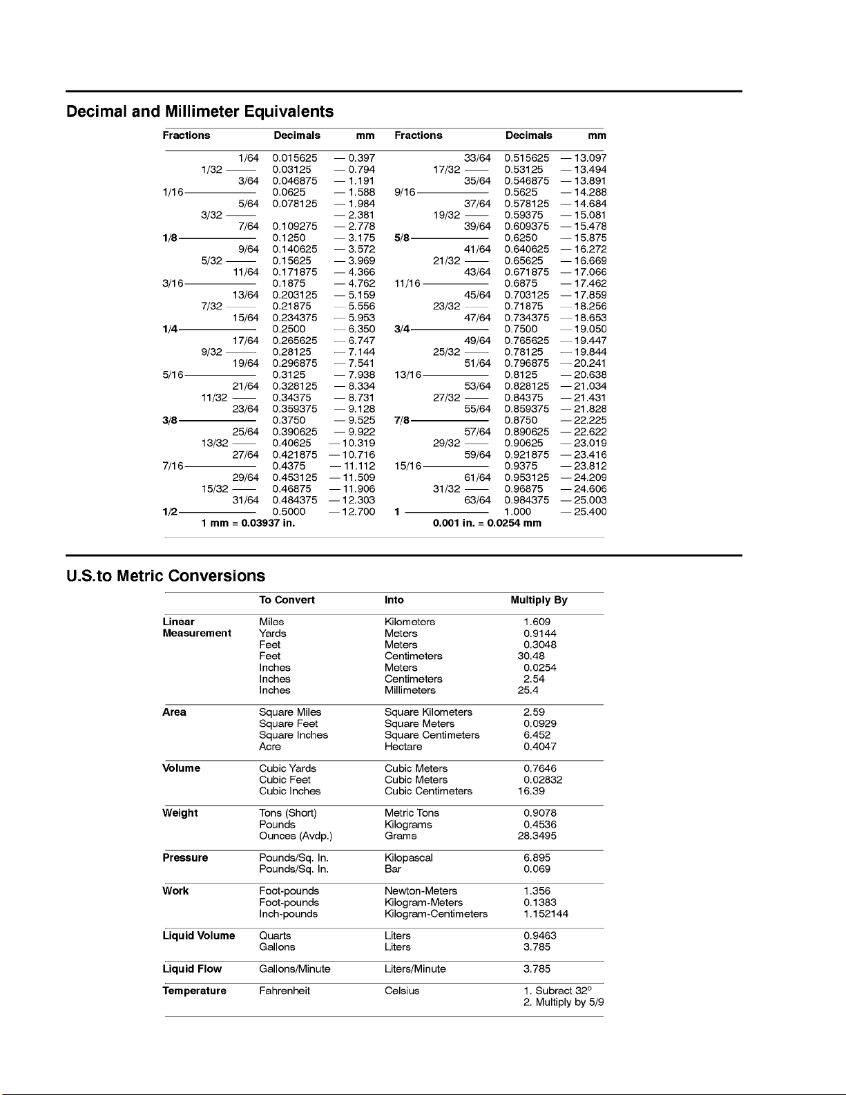
Equivalents and Conversions
0.09375
Product Records and Maintenance
Page 2 -- 2
Rev. C
ProCore 648
Page 13
Torque Specifications
Recommended fastener torque values are listed in the
following tables. For critical applications, as determined
by Toro, either the recommended torque or a torque that
is unique to the application is clearly identified and specified in this Service Manual.
These Torque Specifications for the installation and
tightening of fasteners shall apply to all fasteners which
do not have a specific requirement identified in this Service Manual. The following factors shall be considered
when applying torque: cleanliness of the fastener, use
of a thread sealant (e.g. Loctite), degree of lubrication
on the fastener, presence of a prevailing torque feature,
hardness of the surface underneath the fastener’s head
or similar condition which affects the installation.
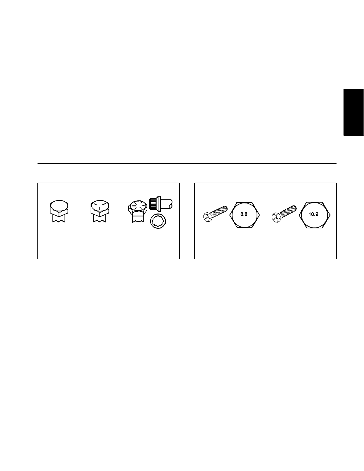
Fastener Identification
As noted in the following tables, torque values should be
reduced by 25% for lubricated fasteners to achieve
the similar stress as a dry fastener. Torque values may
also have to be reduced when the fastener is threaded
into aluminum or brass. The specific torque value
should be determined based on the aluminum or brass
material strength, fastener size, length of thread engagement, etc.
The standard method of verifying torque shall be performed by marking a line on the fastener (head or nut)
and mating part, then back off fastener 1/4 of a turn.
Measure the torque required to tighten the fastener until
the lines match up.
Product Records
and Maintenance
Grade 1
Grade 5 Grade 8
Inch Series Bolts and Screws
Figure 1 Figure 2
Class 8.8 Class 10.9
Metric Bolts and Screws
ProCore 648
Page 2 – 3
Product Records and Maintenance
Page 14
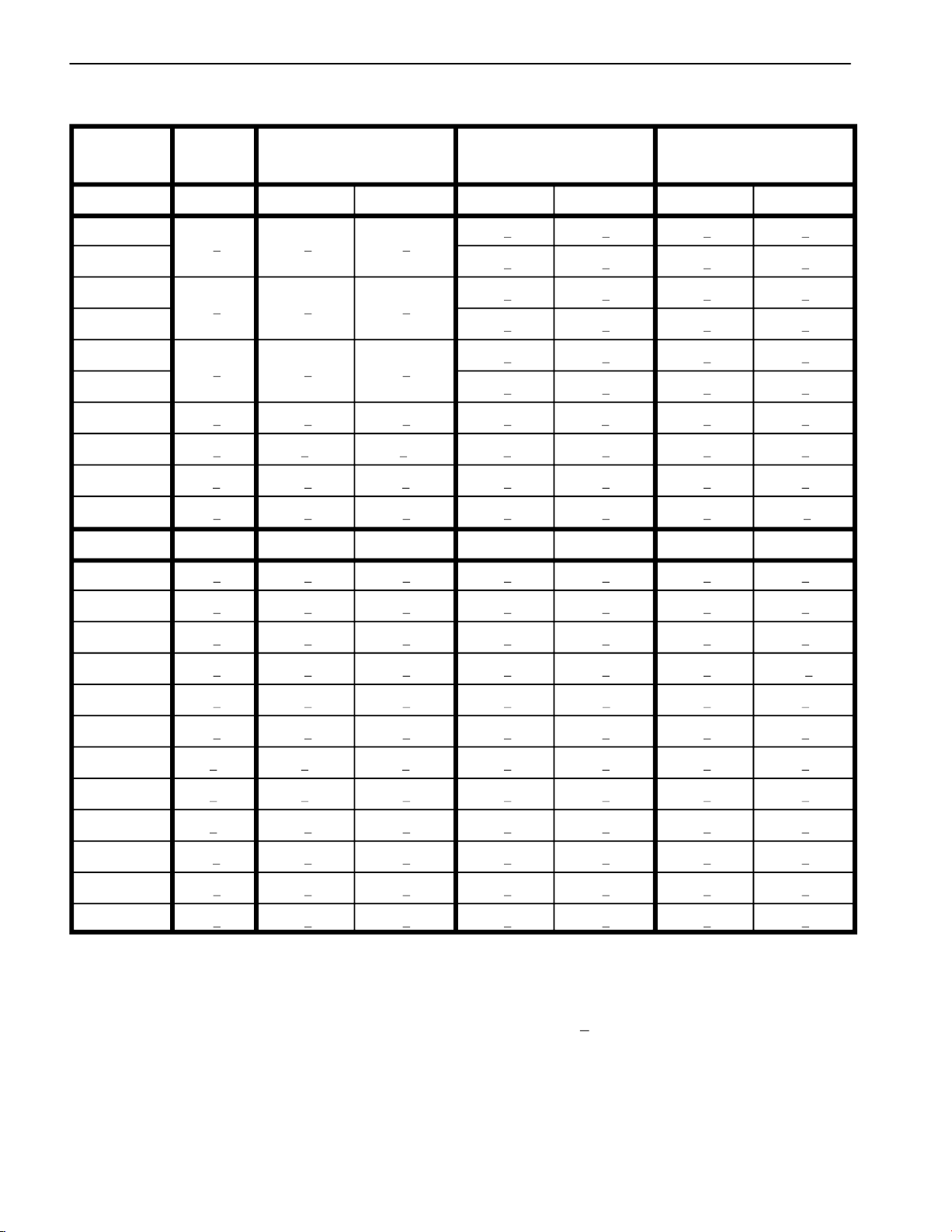
Standard Torque for Dry, Zinc Plated and Steel Fasteners (Inch Series)
Grade 1, 5 & SAE Grade 1 Bolts, Screws, Studs & SAE Grade 5 Bolts, Screws, Studs & SAE Grade 8 Bolts, Screws, Studs &
Thread Size
8 with Thin Sems with Regular Height Nuts Sems with Regular Height Nuts Sems with Regular Height Nuts
Height Nuts (SAE J995 Grade 2 or Stronger Nuts) (SAE J995 Grade 2 or Stronger Nuts) (SAE J995 Grade 5 or Stronger Nuts)
in–lb in–lb N–cm in–lb N–cm in–lb N–cm
# 6 – 32 UNC 15 + 2 170 + 20 23 + 2 260 + 20
# 6 – 40 UNF
# 8 – 32 UNC 29 + 3 330 + 30 41 + 4 460 + 45
# 8 – 36 UNF
# 10 – 24 UNC 42 + 4 475 + 45 60 + 6 675 + 70
# 10 – 32 UNF
1/4 – 20 UNC 48 + 7 53 + 7 599 + 79 100 + 10 1125 + 100 140 + 15 1580 + 170
1/4 – 28 UNF 53 + 7 65 + 10 734 + 113 115 + 10 1300 + 100 160 + 15 1800 + 170
5/16 – 18 UNC 115 + 15 105 + 17 1186 + 169 200 + 25 2250 + 280 300 + 30 3390 + 340
5/16 – 24 UNF 138 + 17 128 + 17 1446 + 192 225 + 25 2540 + 280 325 + 30 3670 + 340
3/8 – 16 UNC 16 + 2 16 + 2 22 + 3 30 + 3 41 + 4 43 + 4 58 + 5
3/8 – 24 UNF 17 + 2 18 + 2 24 + 3 35 + 3 47 + 4 50 + 4 68 + 5
7/16 – 14 UNC 27 + 3 27 + 3 37 + 4 50 + 5 68 + 7 70 + 7 95 + 9
7/16 – 20 UNF 29 + 3 29 + 3 39 + 4 55 + 5 75 + 7 77 + 7 104 + 9
10 + 2
+ 2 13 + 2
13 + 2
+ 2
18 + 2
+ 2 30 + 5
ft–lb ft–lb N–m ft–lb N–m ft–lb N–m
+ 2 147 + 23
25 + 5
+ 5
+ 5 339 + 56
282 + 30
+ 23
17 + 2 190 + 20 25 + 2 280 + 20
+ 30
31 + 3 350 + 30 43 + 4 485 + 45
+ 56
48 + 4 540 + 45 68 + 6 765 + 70
1/2 – 13 UNC 30 + 3 48 + 7 65 + 9 75 + 8 102 + 11 105 + 10 142 + 14
1/2 – 20 UNF 32 + 3 53 + 7 72 + 9 85 + 8 115 + 11 120 + 10 163 + 14
5/8 – 11 UNC 65 + 10 88 + 12 119 + 16 150 + 15 203 + 20 210 + 20 285 + 27
5/8 – 18 UNF 75 + 10 95 + 15 129 + 20 170 + 15 230 + 20 240 + 20 325 + 27
3/4 – 10 UNC 93 + 12 140 + 20 190 + 27 265 + 25 359 + 34 375 + 35 508 + 47
3/4 – 16 UNF 115 + 15 165 + 25 224 + 34 300 + 25 407 + 34 420 + 35 569 + 47
7/8 – 9 UNC 140 + 20 225 + 25 305 + 34 430 + 45 583 + 61 600 + 60 813 + 81
7/8 – 14 UNF 155 + 25 260 + 30 353 + 41 475 + 45 644 + 61 660 + 60 895 + 81
NOTE: Reduce torque values listed in the table above
by 25% for lubricated fasteners. Lubricated fasteners
are defined as threads coated with a lubricant such as
oil, graphite or thread sealant such as Loctite.
NOTE: The nominal torque values listed above for
Grade 5 and 8 fasteners are based on 75% of the minimum proof load specified in SAE J429. The tolerance is
approximately +
10% of the nominal torque value. Thin
height nuts include jam nuts.
NOTE: Torque values may have to be reduced when
installing fasteners into threaded aluminum or brass.
The specific torque value should be determined based
on the fastener size, the aluminum or base material
strength, length of thread engagement, etc.
Product Records and Maintenance
Page 2 – 4
ProCore 648
Page 15
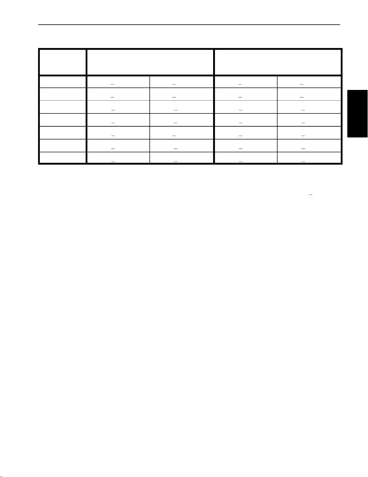
Standard Torque for Dry, Zinc Plated and Steel Fasteners (Metric Fasteners)
Class 8.8 Bolts, Screws and Studs with
Thread Size
M8 X 1.25 19 + 2 ft–lb 26 + 3 N–m 27 + 2 ft–lb 36 + 3 N–m
M10 X 1.5 38 + 4 ft–lb 52 + 5 N–m 53 + 5 ft–lb 72 + 7 N–m
M12 X 1.75 66 + 7 ft–lb 90 + 10 N–m 92 + 9 ft–lb 125 + 12 N–m
M16 X 2.0 166 + 15 ft–lb 225 + 20 N–m 229 + 22 ft–lb 310 + 30 N–m
M20 X 2.5 325 + 33 ft–lb 440 + 45 N–m 450 + 37 ft–lb 610 + 50 N–m
NOTE: Reduce torque values listed in the table above
by 25% for lubricated fasteners. Lubricated fasteners
are defined as threads coated with a lubricant such as
oil, graphite or thread sealant such as Loctite.
NOTE: Torque values may have to be reduced when
installing fasteners into threaded aluminum or brass.
The specific torque value should be determined based
on the fastener size, the aluminum or base material
strength, length of thread engagement, etc.
Size
M5 X 0.8 57 + 5 in–lb 640 + 60 N–cm 78 + 7 in–lb 885 + 80 N–cm
M6 X 1.0 96 + 9 in–lb 1018 + 100 N–cm 133 + 13 in–lb 1500 + 150 N–cm
Regular Height Nuts
(Class 8 or Stronger Nuts)
Height Nuts
NOTE: The nominal torque values listed above are
based on 75% of the minimum proof load specified in
SAE J1199. The tolerance is approximately +
nominal torque value.
Class 10.9 Bolts, Screws and Studs with
Regular Height Nuts
(Class 10 or Stronger Nuts)
Height Nuts
10% of the
Product Records
and Maintenance
ProCore 648
Page 2 – 5
Product Records and Maintenance
Page 16
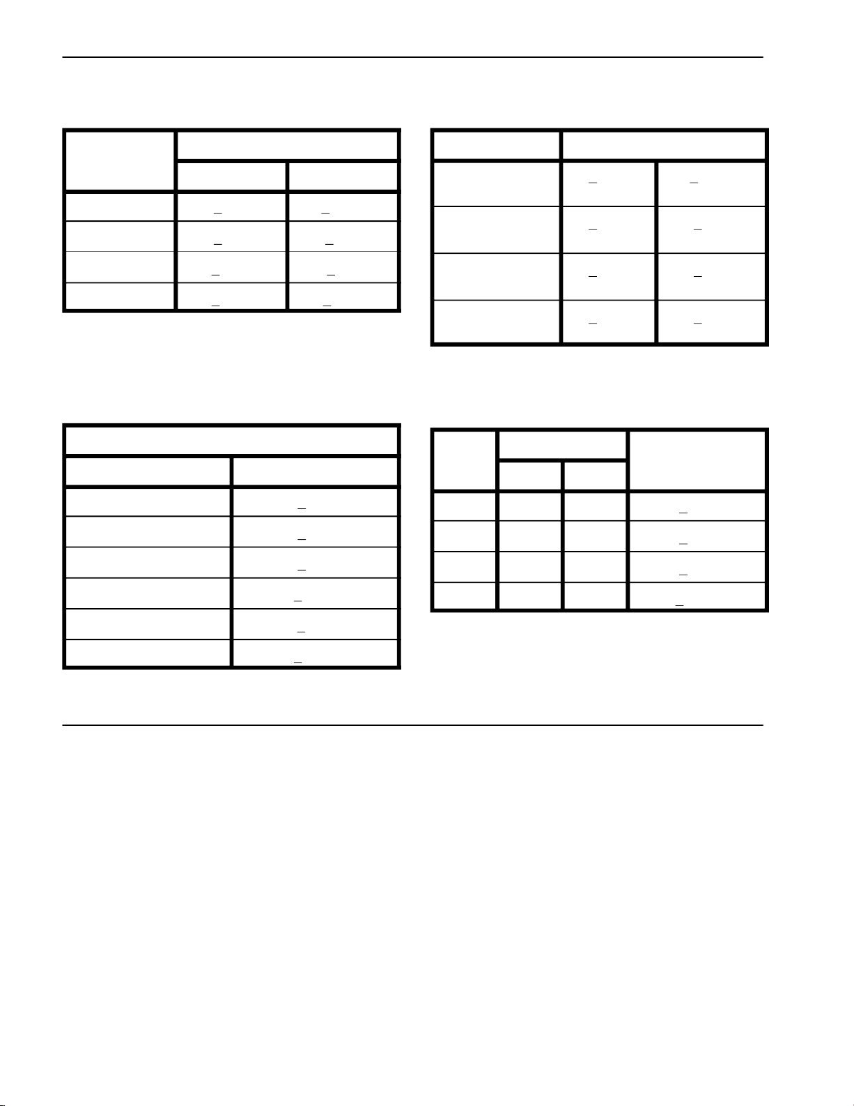
Other Torque Specifications
SAE Grade 8 Steel Set Screws Wheel Bolts and Lug Nuts
Recommended Torque
Size Thread Size
Square Head Hex Socket
1/4 – 20 UNC 140 + 20 in–lb 73 + 12 in–lb
5/16 – 18 UNC 215 + 35 in–lb 145 + 20 in–lb
3/8 – 16 UNC 35 + 10 ft–lb 18 + 3 ft–lb
1/2 – 13 UNC 75 + 15 ft–lb 50 + 10 ft–lb
Thread Cutting Screws
(Zinc Plated Steel)
Type 1, Type 23 or Type F
Thread Size Baseline Torque*
No. 6 – 32 UNC 20 + 5 in–lb
No. 8 – 32 UNC 30 + 5 in–lb
Thread Size
7/16 – 20 UNF
Grade 5
1/2 – 20 UNF
Grade 5
M12 X 1.25
Class 8.8
M12 X 1.5
Class 8.8
** For steel wheels and non–lubricated fasteners.
Thread Cutting Screws
(Zinc Plated Steel)
Thread
Size
No. 6 18 20 20 + 5 in–lb
No. 8 15 18 30 + 5 in–lb
Threads per Inch
Type A Type B
Recommended Torque**
65 + 10 ft–lb 88 + 14 N–m
80 + 10 ft–lb 108 + 14 N–m
80 + 10 ft–lb 108 + 14 N–m
80 + 10 ft–lb 108 + 14 N–m
Torque* Baseline Torque*
No. 10 – 24 UNC 38 + 7 in–lb
1/4 – 20 UNC 85 + 15 in–lb
5/16 – 18 UNC 110 + 20 in–lb
3/8 – 16 UNC 200 + 100 in–lb
Conversion Factors
in–lb X 11.2985 = N–cm N–cm X 0.08851 = in–lb
ft–lb X 1.3558 = N–m N–m X 0.7376 = ft–lb
No. 10 12 16 38 + 7 in–lb
No. 12 11 14 85 + 15 in–lb
* Hole size, material strength, material thickness & finish
must be considered when determining specific torque
values. All torque values are based on non–lubricated
fasteners.
Product Records and Maintenance
Page 2 – 6
ProCore 648
Page 17

Table of Contents
Chapter 3
Kohler Engine
INTRODUCTION . . . . . . . . . . . . . . . . . . . . . . . . . . . . . . 2
SPECIFICATIONS 3. . . . . . . . . . . . . . . . . . . . . . . . . . . .
GENERAL INFORMATION . . . . . . . . . . . . . . . . . . . . . 4
Fuel Shutoff Valve . . . . . . . . . . . . . . . . . . . . . . . . . . . 4
ADJUSTMENTS 5. . . . . . . . . . . . . . . . . . . . . . . . . . . . . .
Adjust Choke Control . . . . . . . . . . . . . . . . . . . . . . . . 5
Adjust Engine Speed . . . . . . . . . . . . . . . . . . . . . . . . 5
SERVICE AND REPAIRS . . . . . . . . . . . . . . . . . . . . . . 7
Cooling System . . . . . . . . . . . . . . . . . . . . . . . . . . . . . 7
Fuel System . . . . . . . . . . . . . . . . . . . . . . . . . . . . . . . . 8
Exhaust System . . . . . . . . . . . . . . . . . . . . . . . . . . . 10
Engine 12. . . . . . . . . . . . . . . . . . . . . . . . . . . . . . . . . . . .
Belt Tensioners . . . . . . . . . . . . . . . . . . . . . . . . . . . . 16
KOHLER ENGINE SERVICE MANUAL
Kohler
Engine
ProCore 648 Page 3 – 1 Kohler Engine
Page 18

Introduction
This Chapter gives information about specifications and
repair of the Kohler engine used in the ProCore 648.
General engine maintenance procedures are described
in your Operator’s Manual. Information on engine troubleshooting, testing, disassembly, and reassembly is
identified in the Kohler Engine Service Manual that is included at the end of this section.
Most repairs and adjustments require tools which are
commonly available in many service shops. Special
tools are described in the Kohler Engine Service Manual. The use of some specialized test equipment is explained. However, the cost of the test equipment and the
specialized nature of some repairs may dictate that the
work be done at an engine repair facility.
Service and repair parts for Kohler engines are supplied
through your local Kohler dealer or distributor.
Kohler Engine
Page 3 – 2
ProCore 648
Page 19

Specifications
Item Description
Make / Designation Kohler, CH23S, 4–stroke, V–Twin
Air Cooled, OHV
Number of Cylinders 2
Bore x Stroke 3.15” x 2.64” (80 mm x 67 mm)
Total Displacement 41.1 Cubic Inches (674 cc)
Compression Ratio 8.5:1
Dry Weight (approximate) 90 Pounds (41 Kilograms)
Fuel Unleaded, Regular Gasoline (Minimum 87 Octane)
Fuel Tank Capacity 7.5 U.S. Gallons (28.4 Liters)
Governor Mechanical
Idle Speed (no load) 1400 + 50 RPM
High Idle (no load) 3400 + 50 RPM
Engine Oil See Operator’s Manual
Oil Pump Gear driven trochoid type
Kohler
Engine
Crankcase Oil Capacity 2 U.S. Quart (1.9 Liters) with filter
Starter 12 VDC
ProCore 648 Page 3 – 3 Kohler Engine
Page 20
General Information
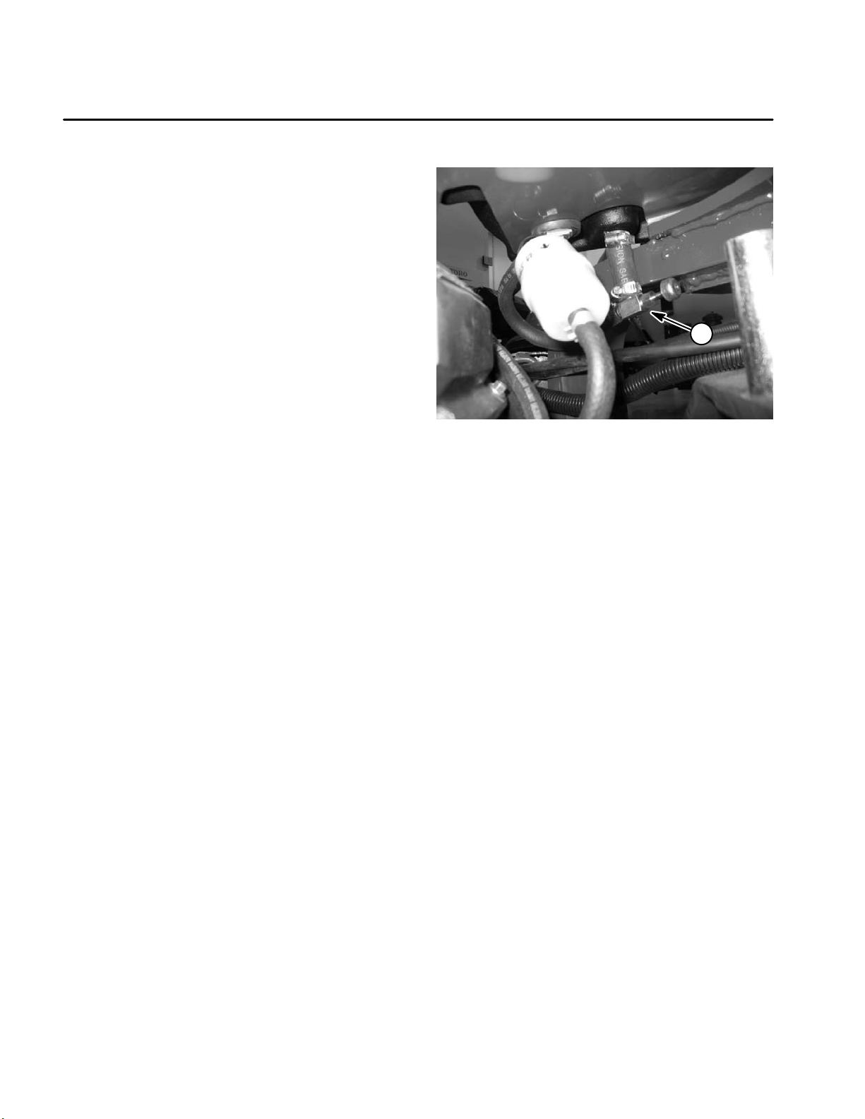
Fuel Shutoff Valve
The fuel shutoff valve located under the fuel tank (Fig.
1) should be closed when removing the fuel tank or engine from the machine. Additionally, close the shutoff
valve if the machine is being transported on a trailer or
when placing the machine in long term storage.
1
Figure 1
1. Fuel shutoff valve (under the fuel tank)
Kohler Engine
Page 3 – 4
ProCore 648
Page 21
Adjustments
Adjust Choke Control
Proper choke operation is dependent upon proper adjustment of choke control cable.
1. Park machine on a level surface, fully raise coring
head, engage parking brake, stop engine and remove
key from the ignition switch.
1
2. Remove air cleaner cover from engine to view choke
plate in carburetor.
3. Move choke control lever to RUN position. Check
that choke plate in carburetor is fully open.
4. Move choke control lever to CHOKE position. Check
that choke plate in carburetor is fully closed.
5. If needed, choke cable can be adjusted by loosening
cable clamp screw and repositioning control cable until
choke plate operates correctly.
6. Install air cleaner cover to engine.
Adjust Engine Speed
1. Allow engine to reach operating temperature before
checking or adjusting engine speed. Park machine on
a level surface, fully raise coring head and apply parking
brake.
2. With engine running, move throttle control lever to
FAST (high idle) position.
3. Using a tachometer, check that engine is operating
at 3400 + 50 RPM.
2
Figure 2
1. Choke cable 2. Cable clamp
1
Kohler
Engine
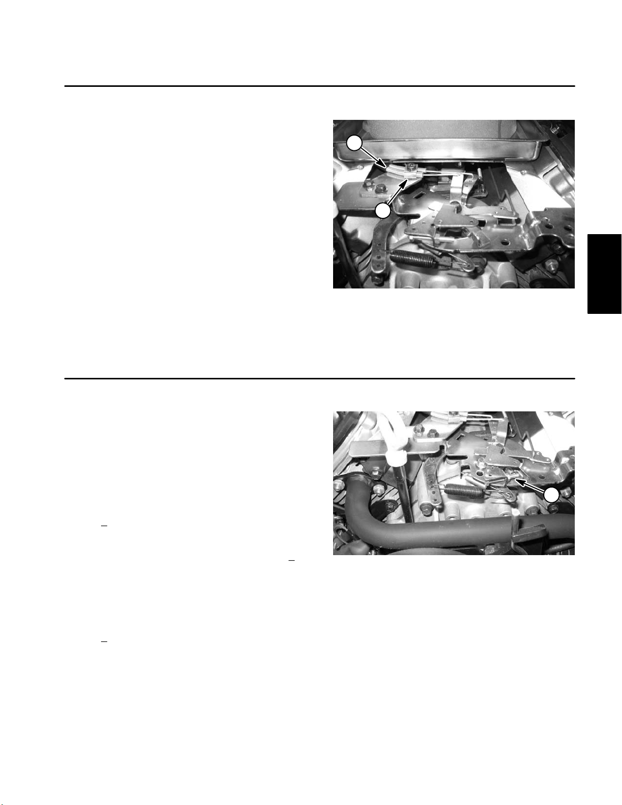
4. If high idle speed is incorrect, adjust high speed
screw on governor assembly until high idle is 3400 + 50
RPM (Fig. 3).
5. Move throttle control lever to SLOW (idle speed)
position.
6. Using a tachometer, check that engine is operating
at 1400 + 50 RPM.
7. For additional information, refer to the Kohler Engine
Service Manual that is included at the end of this Chapter.
ProCore 648 Page 3 – 5 Kohler Engine
Figure 3
1. High speed screw
Page 22

This page is intentionally blank.
Kohler Engine
Page 3 – 6
ProCore 648
Page 23
Service and Repairs
Cooling System
To ensure proper engine cooling, make sure the grass
screen, cooling fins and other external surfaces of the
engine are kept clean at all times.
NOTE: Perform this maintenance procedure at the interval specified in the Operator’s Manual.
IMPORTANT: The engine that powers the ProCore
648 is air–cooled. Operating the engine with dirty or
plugged cooling fins, a blocked grass screen or a
plugged or dirty blower housing will result in engine overheating and engine damage.
1
1
1. Park machine on a level surface, fully raise coring
head, engage parking brake, stop engine and remove
key from the ignition switch.
IMPORTANT: Never clean engine with pressurized
water. Water could enter and contaminate the fuel
system.
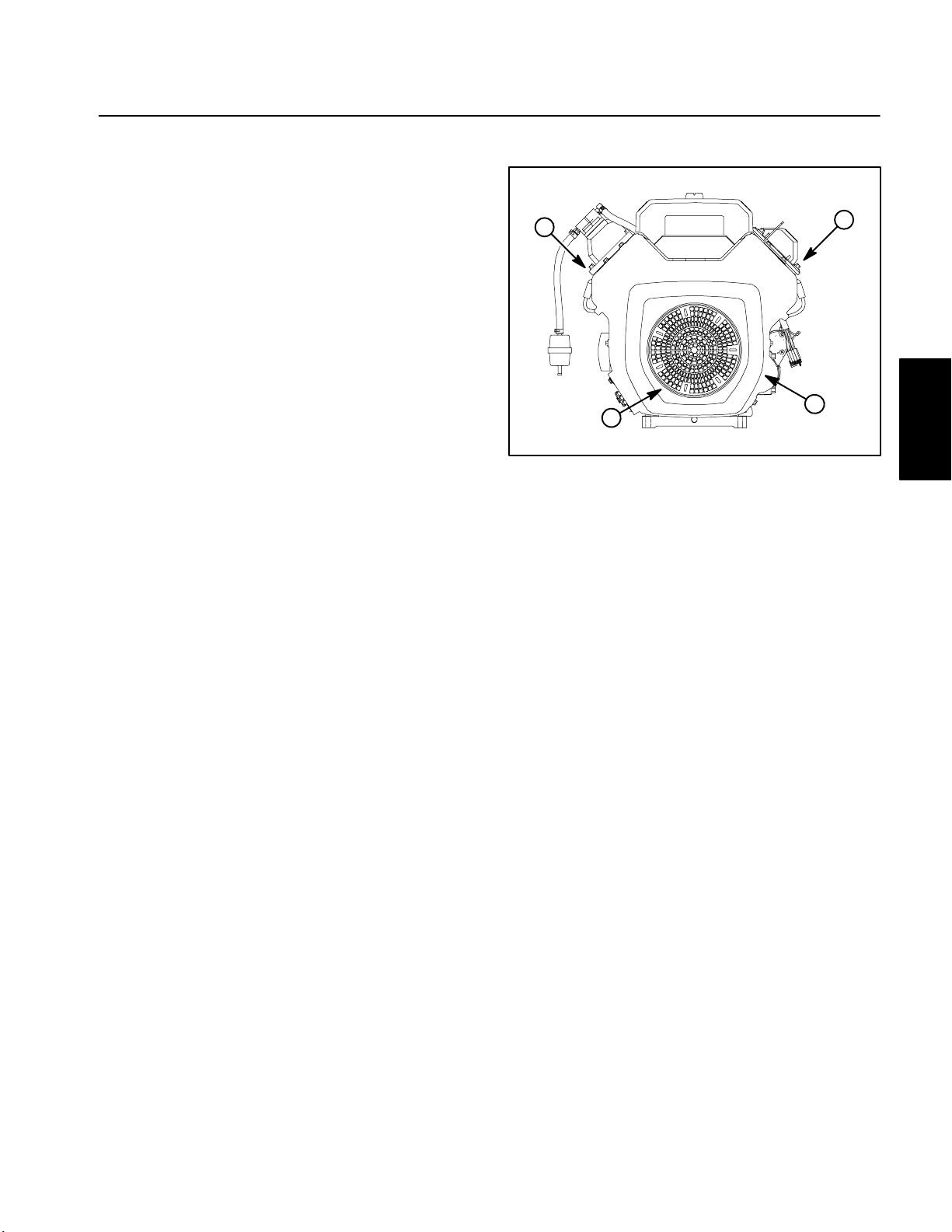
2. Clean cooling fins on both cylinder heads.
3. Clean grass screen and blower housing of dirt and
debris (Fig. 4).
4. If blower housing removal is necessary for cooling
system cleaning, engine needs to be removed from machine (see Engine Removal and Installation in this section).
IMPORTANT: Never operate engine without the
blower housing installed. Overheating and engine
damage will result.
5. Make sure grass screen and blower housing are reinstalled to the engine if removed.
1. Cylinder head
2. Grass screen
2
Figure 4
3. Blower housing
3
Kohler
Engine
ProCore 648 Page 3 – 7 Kohler Engine
Page 24
Fuel System
RIGHT
FRONT
Anti–seize
Lubricant
2
1
12
11
8
10
30 to 60 in–lb
(3.4 to 6.8 N–m)
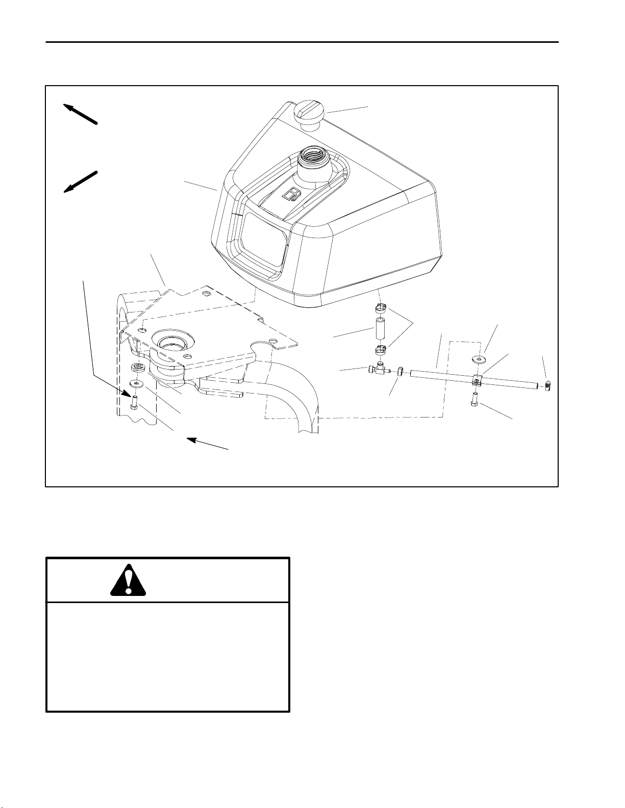
1. Fuel tank
2. Fuel cap
3. Hose clamp
4. Fuel hose
5. Fuel shut–off valve
6. Hose clamp
7. Fuel hose
8. Flat washer (4 used)
DANGER
Because gasoline is highly flammable, use caution when storing or handling it. Do not smoke
while filling the fuel tank. Do not fill fuel tank
while engine is running, hot, or when machine is
in an enclosed area. Always fill fuel tank outside
and wipe up any spilled fuel before starting the
engine. Store fuel in a clean, safety–approved
container and keep cap in place. Use gasoline
for the engine only; not for any other purpose.
8
4
3
7
5
6
Figure 5
9. Clamp
10. Cap screw (4 used)
11. Flange bushing (4 used)
12. Machine frame
Check Fuel Lines and Connections
Check fuel lines and connections periodically as recommended in the Operator’s Manual. Check fuel lines for
deterioration, damage or leaking connections. Replace
hoses, clamps and connections as necessary.
Drain and Clean Fuel Tank
Drain and clean the fuel tank periodically as recommended in the Operator’s Manual. Also, drain and clean
the fuel tank if the fuel system becomes contaminated
or if the machine is to be stored for an extended period.
9
10
6
Kohler Engine
To clean fuel tank, flush tank out with clean solvent.
Make sure tank is free of contaminates and debris.
Page 3 – 8
ProCore 648
Page 25
Fuel Tank Removal (Fig. 5)
1. Park machine on a level surface, fully raise coring
head, engage parking brake, stop engine and remove
key from the ignition switch. Secure coring head with
service latch.
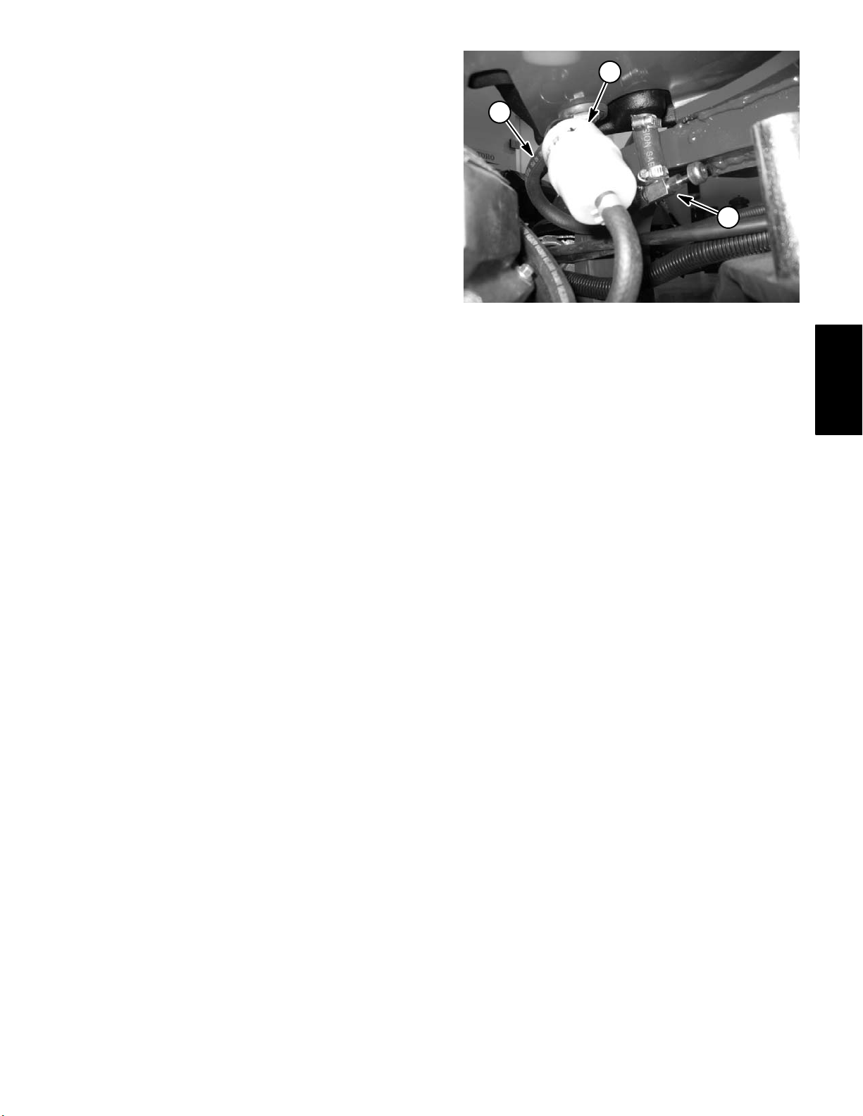
2. Close tank fuel shut–off valve. Disconnect fuel hose
from the fuel filter (Fig. 6).
2
3
3. Use shut–off valve to empty fuel tank into a suitable
container.
4. Remove fuel tank using Figure 5 as a guide.
Fuel Tank Installation (Fig. 5)
1. Install fuel tank to frame using Figure 5 as a guide.
Apply anti–seize lubricant to fuel tank cap screws and
torque screws from 30 to 60 in–lb (3.4 to 6.8 N–m).
2. Connect fuel hose to the fuel filter.
3. Fill fuel tank (see Operator’s Manual). Open fuel
shut–off valve.
4. Return coring head service latch to stored position
before using machine.
1. Fuel shut–off valve
2. Fuel filter
Figure 6
3. Fuel hose
1
Kohler
Engine
ProCore 648 Page 3 – 9 Kohler Engine
Page 26
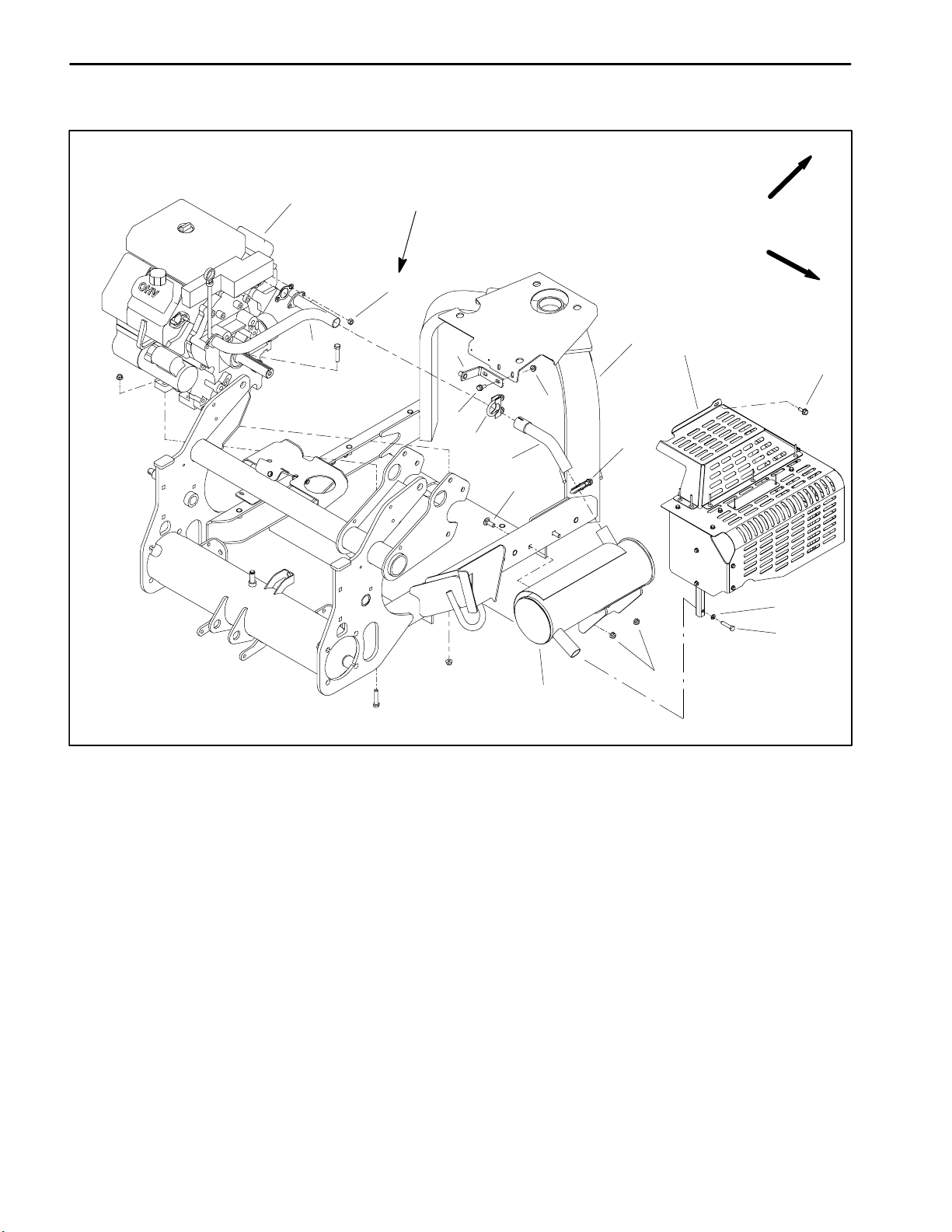
Exhaust System
1
17 to 21 ft–lb
(23.1 to 28.5 N–m)
FRONT
RIGHT
3
4
2
6
5
7
8
8
9
10
11
7
12
1. Engine
2. Exhaust manifold
3. Hex nut (4 used)
4. Frame
5. Flange nut (2 used)
Figure 7
6. Muffler bracket
7. Flange head screw (3 used)
8. Muffler clamp (2 used)
9. Exhaust elbow
10. Carriage screw (2 used)
13
14
15
11. Heat shield
12. Lock washer (2 used)
13. Cap screw (2 used)
14. Flange nut (2 used)
15. Muffler
Kohler Engine
Page 3 – 10
ProCore 648
Page 27

Removal (Fig. 7)
CAUTION
Installation (Fig. 7)
NOTE: Make sure exhaust manifold and engine seal-
ing surfaces are free of debris or damage that may prevent a tight, leak–free seal.
The muffler and exhaust pipe may be hot. To
avoid possible burns, allow the engine and exhaust system to cool before working on the exhaust system.
1. Park machine on a level surface, fully raise coring
head, engage parking brake, stop engine and remove
key from the ignition switch. Secure coring head with
service latch.
2. Remove fasteners that secure exhaust heat shield
to machine (flange head screw and two (2) cap screws
with lock washers). Remove heat shield from machine.
3. Loosen muffler clamps that secure muffler and exhaust elbow.
4. Remove two (2) flange nuts that secure muffler to
frame. Retrieve two (2) carriage screws. Remove muffler and exhaust elbow from machine.
5. If exhaust manifold removal is required, remove four
(4) hex nuts from the exhaust manifold studs on engine.
Separate the exhaust manifold from the engine.
6. Remove exhaust gaskets.
1. If exhaust manifold was removed, place exhaust
gaskets on the engine exhaust manifold studs. Secure
exhaust manifold to engine with four hex nuts. Torque
hex nuts from 17 to 21 ft–lb (23.1 to 28.5 N–m).
IMPORTANT: Finger tighten all exhaust system
fasteners before securing so there is no preload on
exhaust components.
2. Position muffler clamps over exhaust elbow and
muffler inlets.
3. Slide exhaust elbow onto exhaust manifold and then
slide muffler onto elbow.
4. Secure muffler to frame with two (2) carriage screws
and flange nuts.
5. Tighten muffler clamps.
6. Position exhaust heat shield to machine and secure
with flange head screw and two (2) cap screws with lock
washers.
7. Return coring head service latch to stored position
before using machine.
Kohler
Engine
ProCore 648 Page 3 – 11 Kohler Engine
Page 28
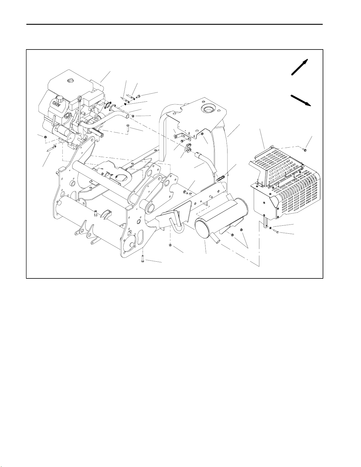
Engine
1
2
3
FRONT
19
21
4
5
6
7
13
9
16
19
11
8
12
13
14
19
8
10
15
20
RIGHT
12
17
18
1. Engine
2. Negative battery cable
3. Wire harness ground
4. Flange screw
5. Lock washer
6. Exhaust manifold
7. Hex nut (4 used)
8. Cap screw (4 used)
9. Frame
10. Flange nut (2 used)
11. Muffler bracket
12. Flange head screw (3 used)
13. Muffler clamp (2 used)
14. Exhaust elbow
Removal (Fig. 8)
1. Park machine on a level surface, fully raise coring
head, engage parking brake, stop engine and remove
key from the ignition switch. Secure coring head with
service latch. Chock wheels to keep the machine from
moving.
2. Disconnect negative (--) and then positive (+) battery
cables at the battery .
3. Remove pump belt cover from machine (see Operator’s Manual).
Kohler Engine
Page 3 -- 12
Figure 8
15. Carriage screw (2 used)
16. Heat shield
17. Lock washer (2 used)
18. Cap screw (2 used)
19. Flange nut (6 used)
20. Muffler
21. Starter cable
4. Remove exhaust system (see Exhaust System Removal in this section).
5. Close fuel tank shut--off valve.
6. Loosen hose clamp and disconnect fuel hose from
the fuel filter on the front side of the engine. Plug fuel
hose to prevent leakage and contamination.
Rev. C
ProCore 648
Page 29
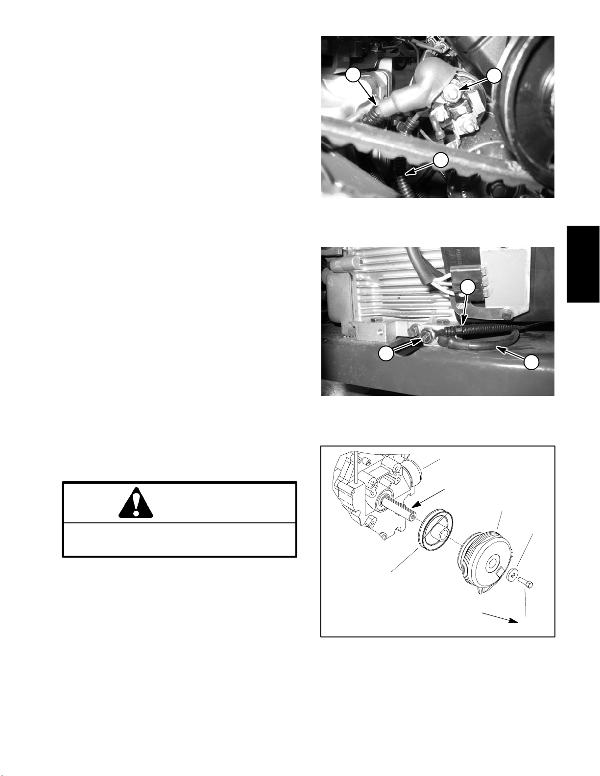
7. Disconnect electrical connections from engine.
NOTE: Label all electrical connections for reassembly
purposes.
A. Remove harness red wire and positive battery
cable from the starter motor solenoid stud (Fig. 9).
B. Disconnect negative battery cable and wire harness ground wire from the front corner of engine
base (Fig. 10). Locate and retrieve starwasher from
between engine and wire connectors.
C. Unplug machine harness connector from electric
clutch.
D. Remove cable tie that secures hourmeter wire to
spark plug wire. Position hourmeter wire clear of engine.
E. Unplug machine wire harness connector from engine connector. Position wiring harness away from
the engine.
8. Remove primary drive belt (coring head) (see Primary Drive Belt in the Service and Repairs section of Chapter 7 – Coring Head).
2
1. Solenoid stud
2. Positive battery cable
3
Figure 9
3. Harness red wire
1
Kohler
Engine
2
9. Remove hydraulic pump drive belt (see Pump Drive
Belt in the Service and Repairs section of Chapter 4 –
Hydraulic System).
10.Remove engine from machine:
A. Connect a hoist or chain fall to lift tabs located on
each of the cylinder heads.
B. Remove four (4) cap screws and flange nuts that
secure the engine to the machine frame.
CAUTION
One person should operate lift or hoist while
another person guides the engine out of the machine.
IMPORTANT: Make sure not to damage the engine,
fuel hoses, hydraulic lines, electrical harness or
other parts while removing the engine.
C. Remove engine from the machine.
1
1. Flange head screw
2. Wire harness ground
2
(67.8 to 74.6 N–m)
3
Figure 10
3. Negative battery cable
1
Anti–seize
Lubricant
3
4
50 to 55 ft–lb
5
11.If needed, remove electric clutch (see Electric Clutch
in the Service and Repairs section of Chapter 5 – Electrical System) and hydraulic pump drive pulley from engine (Fig. 11).
1. Engine
2. Pump pulley
3. Electric clutch
Figure 11
4. Hardened washer
5. Cap screw
12.If needed, remove belt tensioning components from
engine (see Belt Tensioners in this section).
ProCore 648 Page 3 – 13 Kohler Engine
Page 30
Installation (Fig. 8) B. Wrap hourmeter wire around spark plug wire and
secure with cable tie.
1. Locate machine on a level surface with key removed
from the ignition switch. Chock wheels to keep the machine from moving.
2. Make sure that all parts removed from the engine
during maintenance or rebuilding are reinstalled to the
engine.
3. If electric clutch and hydraulic pump drive pulley
were removed from engine crankshaft (Fig. 11):
A. Apply anti–seize lubricant to crankshaft.
B. Install hydraulic pump drive pulley with the hub
away from engine.
C. Slide clutch onto crankshaft and secure to crankshaft with screw and hardened washer. Hold hardened washer with pliers to prevent crankshaft from
turning and torque screw from 50 to 55 ft–lb (67.9 to
74.6 N–m).
C. Position negative battery cable and wire harness
ground wire to the front corner of engine base (Fig.
10). Place starwasher between engine and wire connectors and secure with flange head screw.
D. Plug machine harness connector to electric
clutch.
E. Connect red wire and positive battery cable to the
starter motor solenoid stud (Fig. 9).
7. After engine installation, verify pulley alignment
across engine and hydraulic pump pulley faces with a
straight edge. If necessary, loosen two (2) set screws on
hydraulic pump pulley and adjust location of pulley. Retighten pulley set screws after adjustment.
8. Install hydraulic pump drive belt (see Pump Drive
Belt in the Service and Repairs section of Chapter 4 –
Hydraulic System).
4. If removed, install belt tensioner components to engine assembly (see Belt Tensioners in this section).
5. Reinstall engine to machine.
A. Connect a hoist or chain fall to lift tabs located on
each of the cylinder heads.
CAUTION
One person should operate lift or hoist while
another person guides the engine to the machine.
IMPORTANT: Make sure not to damage the engine,
fuel hoses, hydraulic lines, electrical harness or
other parts while installing the engine.
B. Reinstall engine to the machine. Make sure fastener holes of the engine are aligned with the holes in
the machine frame.
C. Secure engine to the frame with four (4) cap
screws and flange nuts. The front two (2) cap screws
should be positioned down through engine and
frame. The rear two (2) cap screws should be up
through frame and engine.
6. Reconnect electrical connections to engine:
9. Adjust hydraulic pump drive belt tension (see Operator’s Manual).
10.Install primary drive belt (coring head) (see Primary
Drive Belt in the Service and Repairs section of Chapter
7 – Coring Head).
11. Remove plug installed in fuel hose during disassembly. Connect fuel hose to the fuel filter and secure with
hose clamp.
12.Install exhaust system (see Exhaust System Installation in this section).
13.Check engine oil level (see Operator’s Manual).
14.Check all wires, control cables and hoses to make
sure that they are not contacted by rotating or moving
parts.
15.Connect positive (+) and then negative (–) battery
cables at the battery.
16.Install pump belt cover to machine (see Operator’s
Manual).
17.Open fuel shut–off valve under the fuel tank.
18.Return coring head service latch to stored position
before using machine.
A. Plug engine wire harness connector into machine
harness connector.
Kohler Engine
Page 3 – 14
ProCore 648
Page 31

This page is intentionally blank.
Kohler
Engine
ProCore 648 Page 3 – 15 Kohler Engine
Page 32

Belt Tensioners
29
30
34
31
32
28
26
33
27
26
23
4
24
41 to 49 ft–lb
(55.6 to 66.4 N–m)
1
Anti–seize
Lubricant
23
25
22
41 to 49 ft–lb
4
23
21
4
(55.6 to 66.4 N–m)
20
19
17
13
18
16
11
15
14
12
8
9
7
2
1. Engine
2. Hydraulic pump drive pulley
3. Electric clutch
4. Flange nut
5. Hardened washer
6. Cap screw
7. Flat washer
8. Grommet
9. Spacer
10. Cap screw
11. Clutch strap
12. Cap screw
8
9
10
7
3
6
5
50 to 55 ft–lb
(67.8 to 74.6 N–m)
Figure 12
13. Flange nut
14. Flat washer
15. Idler arm assembly
16. Washer
17. Idler spacer
18. Idler arm spacer
19. Torsion spring
20. Idler pulley
21. Hardened washer
22. Cap screw
23. Cap screw
24. Spacer (.750” long)
25. Idler mounting bracket
26. Spacer (.560” long)
27. Lock nut
28. Idler support
29. Flange head screw
30. Spring bracket
31. Spring
32. Flange head screw
33. Idler pulley
34. Bracket (fastens to machine frame)
Kohler Engine
Page 3 – 16
ProCore 648
Page 33

Removal (Fig. 12)
Installation (Fig. 12)
1. Release tension on idler torsion spring (item 19):
CAUTION
Be careful when removing or applying tension
from or to the torsion spring of the idler pulley.
The spring is under heavy load and may cause
personal injury.
A. Insert nut driver or small piece of pipe onto the
end of the torsion spring.
B. Push down on the spring end and unhook the
spring from the idler mounting bracket.
2. Remove belt tensioner components from engine as
needed using Figure 12 as a guide.
1. Install belt tensioner components to engine using
Figure 12 as a guide.
2. Install the hydraulic pump drive belt and primary
drive belt (coring head).
3. Apply tension to idler torsion spring (item 19):
A. Insert nut driver or small piece of pipe onto the
end of the torsion spring.
B. Push down on the spring end and hook the spring
under the idler mounting bracket notch. Release the
spring slowly to lock it into place.
4. Adjust the hydraulic pump drive belt (see Operator’s
Manual) and primary drive belt (coring head) (see Primary Drive Belt in the Service and Repairs section of
Chapter 7 – Coring Head).
Kohler
Engine
ProCore 648 Page 3 – 17 Kohler Engine
Page 34

This page is intentionally blank.
Kohler Engine
Page 3 – 18
ProCore 648
Page 35

Table of Contents
Chapter 4
Hydraulic System
SPECIFICATIONS 2.............................
GENERAL INFORMATION 4.....................
Hydraulic Hoses 4............................
Hydraulic Fitting Installation 4...................
Pushing/Pulling Machine 6.....................
Check Hydraulic Fluid 6.......................
Relieving Hydraulic System Pressure 6..........
HYDRAULIC SCHEMATIC 7.....................
HYDRAULIC FLOW DIAGRAMS 8................
Traction Circuit 8..............................
Coring Head Raise/Lower Circuits 10............
SPECIAL TOOLS 12............................
Hydraulic Pressure Test Kit 12..................
Hydraulic Tester (Pressure and Flow) 12.........
Hydraulic Test Fitting Kit 13.....................
Wheel Hub Puller 13..........................
TROUBLESHOOTING 14........................
TESTING 17...................................
Charge Pressure Test 18.......................
Coring Head Raise/Lower Relief (R1)
Pressure Test 20............................
Traction (Piston) Pump (P1) Flow Test 22........
Traction Circuit Relief Pressure Test 24..........
Gear Pump (P2) Flow Test 26..................
Wheel Motor Efficiency Test 28.................
SERVICE AND REPAIRS 30.....................
General Precautions for Removing and Installing
Hydraulic System Components 30.............
Check Hydraulic Lines and Hoses 30............
Flush Hydraulic System 31.....................
Hydraulic System Start--up 32..................
Hydraulic Pump Drive Belt 34...................
Hydraulic Pump Control Assembly 36............
Hydraulic (Traction/Charge) Pump 38............
Hydraulic (Traction/Charge) Pump Service 41.....
Wheel Motors 42..............................
Wheel Motor Service 44.......................
Hydraulic Lift Control Manifold 46...............
Hydraulic Lift Control Manifold Service 48........
Lift Cylinder 50...............................
Lift Cylinder Service 52........................
Hydraulic Reservoir 54........................
HYDRO--GEAR BDP--10A/16A/21L HYDROSTATIC
PUMPS SERVICE AND REPAIR MANUAL
SAUER DANFOSS GROUP 2GEAR PUMPS AND MO-
TORS SERVICE MANUAL
SAUER DANFOSS OMEW HYDRAULIC MOTOR
SERVICE MANUAL
System
Hydraulic
ProCore 648 Hydraulic SystemPage 4 -- 1
Rev. C
Page 36

Specifications
Item Description
Traction Pump (P1) Variable displacement piston pump
Displacement at full stroke (per revolution) .976 Cubic Inches (16 cc)
Forward relief pressure 2900 PSI (200 Bar)
Reverse relief pressure 2900 PSI (200 Bar)
Charge/Lift Pump (P2) Gear pump
Displacement (per revolution) .37 Cubic Inches (6.1 cc)
Charge Pressure 40 PSI (2.8 Bar)
Lift System Relief (R1) Pressure 1000 PSI (69 Bar)
Front Wheel Motor Orbital rotor motor
Displacement 24 Cubic Inches (393 cc)
Rear Wheel Motors Orbital rotor motor
Displacement 12 Cubic Inches (197 cc)
Hydraulic Filter Spin–on cartridge type
Hydraulic Oil See Operator’s Manual
Hydraulic Reservoir Capacity 1.75 U.S. Gal. (6.6 L)
Total Hydraulic System Capacity 3 U.S. Gal. (11.4 L) (Approximate)
Hydraulic System Page 4 – 2 ProCore 648
Page 37

This page is intentionally blank.
System
Hydraulic
ProCore 648 Page 4 – 3 Hydraulic System
Page 38

General Information
Hydraulic Hoses
Hydraulic hoses are subject to extreme conditions such
as pressure differentials during operation and exposure
to weather, sun, chemicals, very warm storage conditions, or mishandling during operation and maintenance. These conditions can cause damage or
premature deterioration. Some hoses are more susceptible to these conditions than others. Inspect the hoses
frequently for signs of deterioration or damage.
WARNING
Before disconnecting or performing any work
on hydraulic system, relieve all pressure in
system. See Relieving Hydraulic System Pressure in this section.
When replacing a hydraulic hose, be sure that the hose
is straight (not twisted) before tightening the fittings.
This can be done by observing the imprint on the hose.
Use two wrenches; hold the hose straight with one
wrench and tighten the hose swivel nut onto the fitting
with the other wrench.
Hydraulic Fitting Installation
O–Ring Face Seal
1. Make sure both threads and sealing surfaces are
free of burrs, nicks, scratches, or any foreign material.
2. Make sure the O–ring is installed and properly
seated in the groove. It is recommended that the O–ring
be replaced any time the connection is opened.
3. Lubricate the O–ring with a light coating of oil.
4. Put the tube and nut squarely into position on the
face seal end of the fitting and tighten the nut until finger
tight.
Keep body and hands away from pin hole leaks
or nozzles that eject hydraulic fluid under high
pressure. Use paper or cardboard, not hands,
to search for leaks. Hydraulic fluid escaping
under pressure can have sufficient force to
penetrate the skin and cause serious injury. If
fluid is injected into the skin, it must be surgically removed within a few hours by a doctor
familiar with this type of injury. Gangrene may
result from such an injury.
Nut
Sleeve
Seal
Body
Figure 1
5. Mark the nut and fitting body. Hold the body with a
wrench. Use another wrench to tighten the nut to the correct Flats From Finger Tight (F.F.F.T.). The markings on
the nut and fitting body will verify that the connection has
been tightened.
Size F.F.F.T.
4 (1/4 in. nominal hose or tubing) 0.75 + 0.25
6 (3/8 in.) 0.75 + 0.25
8 (1/2 in.) 0.75 + 0.25
10 (5/8 in.) 1.00 +
12 (3/4 in.) 0.75 + 0.25
16 (1 in.) 0.75 +
0.25
0.25
Finger Tight After Proper Tightening
Final
Position
Mark Nut
and Body
Extend Line
Figure 2
Initial
Position
Hydraulic System Page 4 – 4 ProCore 648
Page 39

SAE Straight Thread O–Ring Port – Non–adjustable
1. Make sure both threads and sealing surfaces are
free of burrs, nicks, scratches, or any foreign material.
2. Always replace the O–ring seal when this type of fitting shows signs of leakage.
3. Lubricate the O–ring with a light coating of oil.
O–Ring
4. Install the fitting into the port and tighten it down full
length until finger tight.
5. Tighten the fitting to the correct Flats From Finger
Tight (F.F.F.T.).
Size F.F.F.T.
4 (1/4 in. nominal hose or tubing) 1.00 +
6 (3/8 in.) 1.50 + 0.25
8 (1/2 in.) 1.50 + 0.25
10 (5/8 in.) 1.50 + 0.25
12 (3/4 in.) 1.50 +
16 (1 in.) 1.50 +
0.25
0.25
0.25
NOTE: Installation torque values for non–adjustable fittings are listed in Figure 4. These torque values should
only be used when a fitting can be accessed with a
socket. Use of an offset wrench (e.g. crowfoot wrench)
will affect torque wrench accuracy and should not be
used.
SAE Straight Thread O–Ring Port – Adjustable
1. Make sure both threads and sealing surfaces are
free of burrs, nicks, scratches, or any foreign material.
2. Always replace the O–ring seal when this type of fitting shows signs of leakage.
Figure 3
Fitting Size Installation Torque
4 9–10 ft–lb (12–13 N–m)
6 20–21 ft–lb (27–28 N–m)
8 35–37 ft–lb (47–50 N–m)
10 60–66 ft–lb (81–89 N–m)
12 81–87 ft–lb (110–117 N–m)
16 121–131 ft–lb (164–177 N–m)
Figure 4
System
Hydraulic
3. Lubricate the O–ring with a light coating of oil.
4. Turn back the jam nut as far as possible. Make sure
the back up washer is not loose and is pushed up as far
as possible (Step 1).
5. Install the fitting into the port and tighten finger tight
Figure 5
Lock Nut
Back–up Washer
O–Ring
until the washer contacts the face of the port (Step 2).
6. To put the fitting in the desired position, unscrew it by
the required amount, but no more than one full turn
(Step 3).
Step 1
Step 3
7. Hold the fitting in the desired position with a wrench
and turn the jam nut with another wrench to the correct
Flats From Finger Tight (F.F.F.T.) (Step 4).
Size F.F.F.T.
4 (1/4 in. nominal hose or tubing) 1.00 + 0.25
6 (3/8 in.) 1.50 + 0.25
8 (1/2 in.) 1.50 + 0.25
10 (5/8 in.) 1.50 +
12 (3/4 in.) 1.50 +
16 (1 in.) 1.50 +
0.25
0.25
0.25
Step 2
Step 4
Figure 6
ProCore 648 Page 4 – 5 Hydraulic System
Page 40

Pushing/Pulling Machine
IMPORTANT: If push/pull limits are exceeded, severe damage to the piston (traction) pump may occur.
If it becomes necessary to push/pull the machine, push/
pull at a speed below 1 mph (1.6 kph), and for a dis-
tance less than 100 feet (30.5 meters). The piston
(traction) pump is equipped with a by–pass valve that
needs to be rotated counterclockwise (loosened) one
turn for pushing/pulling. The by–pass valve should be
torqued from 95 to 120 in–lb (10.7 to 13.6 N–m) before
the machine is returned to operation.
See Operator’s Manual for pushing/pulling procedures.
Check Hydraulic Fluid
The ProCore 648 hydraulic system is designed to operate on anti–wear hydraulic fluid. The reservoir (Fig. 8)
holds about 1.75 gallons (6.6 liters) of hydraulic fluid.
Check level of hydraulic fluid daily.
Figure 7
1. By–pass valve location
2
1
1
See Operator’s Manual for fluid level checking procedure and hydraulic oil recommendations.
Relieving Hydraulic System Pressure
Before disconnecting or performing any work on the hydraulic system, all pressure in the hydraulic system
must be relieved. With the coring head fully raised, turn
key switch to OFF and allow engine to stop. Secure coring head with service latch.
To relieve hydraulic pressure in traction circuit, move
traction lever to both forward and reverse directions.
Figure 8
1. Hydraulic reservoir 2. Hydraulic reservoir cap
To relieve lift system pressure, turn key switch to ON
(engine not running). Move traction lever to forward direction and depress lower switch on handle to lower coring head onto service latch. Return key switch to OFF
when pressure has been relieved. Remove key from the
ignition switch.
Hydraulic System Page 4 – 6 ProCore 648
Page 41

Hydraulic Schematic
G1
ORF1
LIFT
CYLINDER
CYL
SVR
SVL
R1
SVQ
R2
PV
CONTROL
P
CHG
G2
FORWARD
T
’B’ PORT
(BOTTOM)
’P’ PORT
MANIFOLD
FRONT
WHEEL
M1
System
Hydraulic
P1
P2
’A’ PORT
(TOP)
COMPONENT
P1
P2
PV
R1
R2
M1
M2
M3
ORF1
CIR
.98
.37
--
--
--
23.8
12.1
12.1
.050
GPM
10.5
4.1
PSI
2900
--
--
40
--
1000
--
40
--
--
--
--
--
--
--
--
ProCore 648 Hydraulic SystemPage 4 -- 7
Rev. C
’P’ PORT
’P’ PORT
M2 M3
ProCore 648
Hydraulic Schematic
All solenoids are shown as
de--energized
Page 42

Hydraulic Flow Diagrams
G1
ORF1
CYL
SVR
(NOT ENERGIZED)
R1
SVQ
R2
PV
P
CHG
G2
FORWARD
T
(NOT ENERGIZED)
’B’ PORT
(BOTTOM)
’P’ PORT
SVL
(NOT ENERGIZED)
CONTROL
MANIFOLD
FRONT
WHEEL
M1
LIFT
CYLINDER
P2
P1
’A’ PORT
(TOP)
’P’ PORT
M2 M3
’P’ PORT
Traction Circuit (Forward Shown)
Working Pressure
Low Pressure (Charge)
Return or Suction
Flow
Rev. C
ProCore 648Hydraulic System Page 4 -- 8
Page 43

Traction Circuit
The traction (piston) pump (P1) is driven by the engine
through the pulleys and pump drive belt. The traction circuit of the hydraulic system acts essentially as a closed
loop. Taking its suction directly from the return side of the
wheel motors of the traction circuit, the traction (piston)
pump supplies oil flow to the wheel motors through the
supply side of the traction circuit.
The gear pump (P2) is attached to the traction pump and
is directly coupled to it. The gear pump provides charge
oil to replace small amounts of traction pump internal oil
leakage. Hydraulic charge oil is supplied to the traction
circuit from the gear pump, through the lift control manifold (manifold port P, proportional valve PV and manifold port CHG) and past the charge circuit check valve
in the return side of the traction circuit. Proportional
valve PV ensures that sufficient gear pump flow is always available for the charge oil needs of the traction circuit. Gear pump flow in excess of charge circuit needs
is available to raise/lower the coring head. After charge
and raise/lower requirements are met, excess P2 flow
is directed to the hydraulic reservoir through the hydraulic oil filter.
Forward Direction
Reverse Direction
The traction circuit operates essentially the same in reverse as it does in the forward direction. However, the
flow through the circuit is reversed. When the traction lever is moved to the reverse position, the linkage from the
lever positions the swash plate in the traction motor so
oil flows out the upper port of the pump. Oil flow from the
pump goes to the wheel motors (rear motors first and
then front motor) and turns them in the reverse direction.
Maximum reverse traction pressure is limited by a 2900
PSI (200 Bar) relief valve located in the top of the pump
assembly.
Oil flowing from the wheel motors returns to the bottom
port of the traction pump and is continuously pumped
out the top port as long as the traction lever is held in the
reverse direction.
With the engine running and the traction lever in the neutral position, the traction pump supplies no flow to the
wheel motors. When the traction lever is moved to the
forward position, the linkage from the lever positions the
swash plate in the traction pump so oil flows out the lower port of the pump. Oil flow from the pump is directed
to the wheel motors (front motor first and then rear motors) and turns them in the forward direction. Maximum
forward traction pressure is limited by a 2900 PSI (200
Bar) relief valve located in the bottom of the pump assembly.
Oil flowing from the rear wheel motors returns to the top
port of the traction pump and is continuously pumped
out the bottom port as long as the traction lever is held
in the forward direction.
System
Hydraulic
ProCore 648 Hydraulic SystemPage 4 – 9
Page 44

ORF1
CYL
LIFT
CYLINDER
(EXTENDING)
G1
FROM
GEAR
PUMP
PV
TRACTION
PUMP
TO
R1
G2
SVR
(ENERGIZED)
R2
TCHGP
SVQ
(ENERGIZED)
ORF1
SVL
(NOT
ENERGIZED)
SVL
(ENERGIZED)
CORING HEAD
RAISE
CONTROL
MANIFOLD
LIFT
CYLINDER
CYL
(RETRACTING)
G1
FROM
GEAR
PUMP
PV
TO
TRACTION
PUMP
R1
G2
SVR
(NOT ENERGIZED)
R2
TCHGP
SVQ
(ENERGIZED)
CONTROL
MANIFOLD
LOWER
Coring Head Raise/Lower Circuits
Working Pressure
Low Pressure (Charge)
Return or Suction
Flow
CORING HEAD
ProCore 648Hydraulic System Page 4 – 10
Page 45

Coring Head Raise/Lower Circuits
The gear pump (P2) is attached to the traction pump
(P1) and is directly coupled to it. The gear pump supplies
hydraulic flow for maintaining charge pressure of 40 PSI
(2.8 Bar) to the low pressure side of the traction circuit
and also for raising the aerator coring head. The gear
pump takes its suction from the hydraulic reservoir.
Maximum lift/lower circuit pressure is limited to 1000
PSI (69 Bar) by relief valve R1 in the lift control manifold.
Flow from gear pump (P2) goes to the lift control manifold (port P) and is directed to pressure compensating
valve (PV). Valve PV ensures that sufficient hydraulic
flow is always available to the traction circuit for charge
oil. When not raising the coring head, gear pump flow in
excess of charge circuit needs is directed to the hydraulic oil filter and then returns to the hydraulic reservoir.
Raise Coring Head
When the coring head is to be raised (e.g. traction lever
is released from forward or raise/lower switch is pressed
to raise), solenoid valves SVR and SVQ in the hydraulic
manifold are energized. The valve shift of SVR prevents
gear pump flow return to the reservoir. The valve shift of
SVQ allows oil flow to bypass the control manifold orifice
(ORF1) for more immediate cylinder movement. Oil
flows through the load holding check valve in solenoid
valve SVL to direct gear pump flow out of control manifold port CYL to the lift cylinder. Hydraulic pressure
against the lift cylinder rod extends the cylinder and
raises the coring head.
When the coring head reaches the aerating position, solenoid valves SVQ and SVL in the hydraulic manifold are
de–energized. The valve shift of SVQ removes the bypass to orifice (ORF1). The valve shift of SVL prevents
oil flow from the lift cylinder. Without flow from the lift cylinder, the cylinder and coring head are held in place.
True Core
TM
Ground Following System
When aerating with the ground follow switch in the ON
TM
position, the True Core
Ground Following System hydraulically adjusts the coring head position to ensure
aerating depth consistency over undulating surfaces.
The head high limit and head low limit switches on the
depth actuator assembly are opened or closed depending on movement of the turf guards over ground irregularities. These switches are used as inputs for the
aerator control module to energize or de–energize solenoid valves SVR and SVL in the hydraulic manifold. As
these solenoid valves are energized or de–energized,
the coring head is raised or lowered as described above.
The control manifold orifice (ORF1) restricts oil flow to
and from the lift cylinder to allow more accurate ground
following. Solenoid valve SVQ is always de–energized
when coring head is in the lowered, aerating position.
If the ground follow switch is turned to the OFF position,
the coring head lowers to the manual coring head stops
and the ground following operation is not functional. Solenoid valve SVL is always energized while aerating
when the ground follow switch is in the OFF position.
System
Hydraulic
When the raise input ends (e.g. coring head is fully
raised or raise/lower switch is released), solenoid
valves SVR and SVQ in the hydraulic manifold are de–
energized. The valve shift of SVR allows flow return to
the reservoir. The valve shift of SVQ removes the bypass to orifice (ORF1). The load holding check valve in
solenoid valve SVL prevents oil flow from the lift cylinder.
Without flow to or from the lift cylinder, the cylinder and
coring head positions are held in place.
Lower Coring Head
When the coring head is to be lowered (e.g. raise/lower
switch is pressed to lower), solenoid valves SVQ and
SVL in the hydraulic manifold are energized. The valve
shift of SVQ allows oil flow to bypass the control manifold orifice (ORF1) for more immediate cylinder movement. The valve shift of SVL allows a path for oil flow
from the lift cylinder. The weight of the coring head and
tension of the weight transfer springs cause the lift cylinder to retract and the coring head to lower. Oil flowing
from the retracting lift cylinder returns to the reservoir.
ProCore 648 Hydraulic SystemPage 4 – 11
Page 46

Special Tools
Order these special tools from your Toro Distributor.
Hydraulic Pressure Test Kit
Toro Part Number: TOR47009
Use to take various pressure readings for diagnostic
tests. Quick disconnect fittings provided attach directly
to mating fittings on machine test ports without tools. A
high pressure hose is provided for remote readings.
Contains one each: 1000 PSI (70 Bar), 5000 PSI (350
Bar) and 10000 PSI (700 Bar) gauges. Use gauges as
recommended in Testing section of this chapter.
Hydraulic Tester (Pressure and Flow)
Figure 9
Toro Part Number: TOR214678
This tester requires O--ring Face Seal (ORFS) adapter
fittings for use on this machine (see Hydraulic Test Fitting Kit -- TOR4079 in this section).
1. INLET HOSE: Hose connected from the system circuit to the inlet side of the hydraulic tester.
2. LOAD VALVE: A simulated working load is created
in the circuit by turning the valve to restrict flow.
3. LOW PRESSURE GAUGE: Lowrange gauge toprovide accurate reading at low pressure: 0 to 1000 PSI.
A protector valve cuts out when pressure is about to
exceed the normal range for the gauge. The cutout
pressure is adjustable.
4. HIGH PRESSURE GAUGE: High range gauge
which accommodates pressures beyond the capacity of
the low pressure gauge: 0 to 5,000 PSI.
5. FLOW METER: This meter measures actual oil flow
in the operating circuit with a gauge rated at 15 GPM.
Figure 10
6. OUTLET HOSE: A hose from the outlet side of the
hydraulic tester connects to the hydraulic system circuit.
Rev. C
ProCore 648Hydraulic System Page 4 -- 12
Page 47

Hydraulic Test Fitting Kit
Part Number: TOR4079
This kit includes a variety of O–ring Face Seal fittings to
enable connection of test gauges to the ProCore 648 hydraulic system.
The kit includes: tee’s, unions, reducers, plugs, caps,
and male test fittings.
Wheel Hub Puller
Part Number: TOR4097
The wheel hub puller allows safe removal of the wheel
hub from the shaft of wheel motors.
TORO TEST FITTING KIT (NO. TOR4079)
Figure 11
Figure 12
System
Hydraulic
ProCore 648 Hydraulic SystemPage 4 – 13
Page 48

Troubleshooting
Á
Á
Á
Á
Á
Á
Á
Á
Á
Á
Á
Á
Á
Á
Á
Á
Á
Á
Á
Á
Á
Á
Á
Á
Á
Á
Á
Á
Á
Á
Á
Á
Á
Á
Á
Á
Á
Á
Á
Á
Á
Á
Á
Á
Á
Á
Á
Á
Á
Á
Á
Á
Á
Á
Á
Á
The cause of an improperly functioning hydraulic system is best diagnosed with the use of proper testing
equipment and a thorough understanding of the complete hydraulic system.
A hydraulic system with an excessive increase in heat
or noise has a potential for failure. Should either of these
conditions be noticed, immediately stop the machine,
turn off the engine, locate the cause of the trouble, and
correct it before allowing the machine to be used again.
Problem
Hydraulic oil leaks
БББББББББББ
БББББББББББ
Foaming hydraulic fluid
БББББББББББ
БББББББББББ
БББББББББББ
Hydraulic system operates hot
БББББББББББ
БББББББББББ
БББББББББББ
БББББББББББ
БББББББББББ
БББББББББББ
БББББББББББ
БББББББББББ
БББББББББББ
БББББББББББ
БББББББББББ
Possible Cause
Fitting(s), hose(s), or tube(s) are loose or damaged.
ББББББББББББББББББББ
O–ring(s) or seal(s) are missing or damaged.
ББББББББББББББББББББ
Oil level in reservoir is low.
ББББББББББББББББББББ
Hydraulic system has wrong kind of oil.
ББББББББББББББББББББ
Pump suction line(s) has an air leak.
ББББББББББББББББББББ
Traction system pressure is high due to excessive load.
ББББББББББББББББББББ
Oil level in reservoir is low.
ББББББББББББББББББББ
ББББББББББББББББББББ
Traction pump by–pass valve is open or defective.
ББББББББББББББББББББ
Excessive dirt and debris on hydraulic components.
ББББББББББББББББББББ
Oil is contaminated or too light.
ББББББББББББББББББББ
ББББББББББББББББББББ
Charge pressure is low.
ББББББББББББББББББББ
Air trapped in traction circuit.
ББББББББББББББББББББ
ББББББББББББББББББББ
Wheel motor(s) are worn or damaged.
ББББББББББББББББББББ
Traction pump is worn or damaged.
Continued use of an improperly functioning hydraulic
system could lead to extensive hydraulic component
damage.
The charts that follow contain information to assist in
troubleshooting. There may possibly be more than one
cause for a machine malfunction.
Refer to the Testing section of this Chapter for precautions and specific test procedures.
Neutral is difficult to find or unit oper-
БББББББББББ
ates in one direction only
БББББББББББ
БББББББББББ
БББББББББББ
Traction response is sluggish
БББББББББББ
БББББББББББ
БББББББББББ
БББББББББББ
БББББББББББ
БББББББББББ
БББББББББББ
БББББББББББ
External control linkage is misadjusted, disconnected, binding or
ББББББББББББББББББББ
damaged.
ББББББББББББББББББББ
ББББББББББББББББББББ
Excess air in the traction lines.
ББББББББББББББББББББ
Traction pump is worn or damaged.
Hydraulic oil is very cold.
ББББББББББББББББББББ
ББББББББББББББББББББ
Traction pump by–pass valve is open or worn.
ББББББББББББББББББББ
Engine speed is too low.
ББББББББББББББББББББ
ББББББББББББББББББББ
Pump drive belt is loose or worn.
ББББББББББББББББББББ
Charge pressure is low.
ББББББББББББББББББББ
Traction pump or wheel motor(s) are worn or damaged.
ББББББББББББББББББББ
ProCore 648Hydraulic System Page 4 – 14
Page 49

Problem
Á
Á
Á
Á
Á
Á
Á
Á
Á
Á
Á
Á
Á
Á
Á
Á
Á
Á
Á
Á
Á
Á
Á
Á
Á
Á
Á
Á
Á
Á
Á
Á
Á
Á
Á
Á
Á
Á
Á
Á
Á
Á
Á
Á
Á
Á
Á
Á
Á
Á
Á
Á
Á
Á
Á
Á
Á
Á
Á
Á
Á
Á
Possible Cause
No traction in either direction
БББББББББББ
БББББББББББ
БББББББББББ
БББББББББББ
БББББББББББ
БББББББББББ
БББББББББББ
БББББББББББ
БББББББББББ
БББББББББББ
Wheel motor will not turn
БББББББББББ
БББББББББББ
БББББББББББ
БББББББББББ
Wheel motor will not hold load in
neutral
БББББББББББ
Coring head will not lift or lifts slowly
БББББББББББ
БББББББББББ
БББББББББББ
БББББББББББ
БББББББББББ
БББББББББББ
БББББББББББ
БББББББББББ
БББББББББББ
БББББББББББ
БББББББББББ
БББББББББББ
БББББББББББ
БББББББББББ
Parking brake is engaged.
ББББББББББББББББББББ
Oil level in reservoir is low.
ББББББББББББББББББББ
ББББББББББББББББББББ
Traction pump by–pass valve is open.
ББББББББББББББББББББ
Pump drive belt is loose, worn or broken.
ББББББББББББББББББББ
ББББББББББББББББББББ
Traction cable broken or damaged.
ББББББББББББББББББББ
Charge pressure is low.
ББББББББББББББББББББ
ББББББББББББББББББББ
Hydraulic pump pulley not secure to pump shaft.
ББББББББББББББББББББ
Traction pump or wheel motor(s) are worn or damaged.
Parking brake is engaged (rear wheel motors).
ББББББББББББББББББББ
ББББББББББББББББББББ
Key on wheel motor shaft is sheared or missing.
ББББББББББББББББББББ
Internal parts in wheel motor are damaged.
ББББББББББББББББББББ
Make up fluid from charge pump is not available.
ББББББББББББББББББББ
Wheel motor(s) is/are worn or damaged.
System reset switch needs to be pressed.
ББББББББББББББББББББ
ББББББББББББББББББББ
Engine speed is too low.
ББББББББББББББББББББ
Reservoir oil level is low.
ББББББББББББББББББББ
Pump pulley drive belt is loose or worn.
ББББББББББББББББББББ
ББББББББББББББББББББ
Lift cylinder is binding.
ББББББББББББББББББББ
Coring head is binding.
ББББББББББББББББББББ
ББББББББББББББББББББ
Lift control manifold relief valve (R1) is stuck open.
ББББББББББББББББББББ
Lift control manifold orifice (ORF1) is damaged or plugged.
ББББББББББББББББББББ
ББББББББББББББББББББ
Lift control manifold SVQ cartridge valve solenoid is not being
energized.
ББББББББББББББББББББ
ББББББББББББББББББББ
Gear pump (P2) is worn or damaged.
System
Hydraulic
Coring head raises, but will not stay
БББББББББББ
up
БББББББББББ
ProCore 648 Hydraulic SystemPage 4 – 15
Lift control manifold SVL cartridge stuck open.
ББББББББББББББББББББ
ББББББББББББББББББББ
Lift control manifold SVL cartridge valve leaks.
Page 50

This page is intentionally blank.
ProCore 648Hydraulic System Page 4 – 16
Page 51

Testing
The most effective method for isolating problems in the
hydraulic system is by using hydraulic test equipment
such as pressure gauges and flow meters in the circuits
during various operational checks (see Special Tools
section in this Chapter).
CAUTION
Failure to use gauges with recommended pressure (PSI/Bar) rating as listed in test procedures
could result in damage to gauge and possible
personal injury from leaking hot oil.
Before Performing Hydraulic Tests
All obvious areas such as oil supply, filter, binding linkage, loose fasteners, improper adjustments or improper
operation must be checked before assuming that a hydraulic component is the source of the problem being
experienced.
Precautions For Hydraulic Testing
WARNING
Before disconnecting or performing any work
on the hydraulic system, all pressure in the
system must be relieved. See Relieving Hydraulic System Pressure in the General Information
section of this chapter.
1. Thoroughly clean the machine before disconnecting
or disassembling any hydraulic components. Always
keep in mind the need for cleanliness when working on
hydraulic equipment. Hydraulic system contamination
will cause excessive wear of hydraulic components.
2. Put caps or plugs on any hydraulic lines left open or
exposed during testing or removal of components.
3. The engine must be in good operating condition. Use
a tachometer when making a hydraulic test. Engine
speed will affect the accuracy of hydraulic test results.
4. Because the hydraulic pump is belt driven, check for
proper pump belt adjustment before performing any hydraulic test. Check pump speed with a phototac when
performing hydraulic pump flow tests.
5. To prevent damage to tester or components, the inlet
and the outlet hoses must be properly connected, and
not reversed (when using tester with flow and pressure
capabilities).
6. When using hydraulic tester with flow and pressure
capabilities, completely open load valve in hydraulic
tester before starting engine. This will minimize the possibility of component damage.
7. Install fittings finger tight, far enough to insure that
they are not cross–threaded, before tightening with a
wrench.
8. To prevent hose or tester damage, position the tester
hoses so that moving machine parts will not make contact with them.
System
Hydraulic
Keep body and hands away from pin hole leaks
or nozzles that eject hydraulic fluid under high
pressure. Use paper or cardboard, not hands, to
search for leaks. Hydraulic fluid escaping under
pressure can have sufficient force to penetrate
skin and cause serious injury. If fluid is injected
into the skin, it must be surgically removed
within a few hours by a doctor familiar with this
type of injury. Gangrene may result from such
an injury.
ProCore 648 Hydraulic SystemPage 4 – 17
9. Check and adjust the oil level in the reservoir after
connecting hydraulic test equipment.
10.Check the control linkage for improper adjustment,
binding or broken parts. Make sure control linkage is
functioning properly before conducting hydraulic tests.
11. All hydraulic tests should be made with the hydraulic
oil at normal operating temperature.
Page 52

Charge Pressure Test (Using Pressure Gauge)
G1
PV
R1
G2
PRESSURE
GAUGE
FORWARD
ORF1
CYL
SVR
SVQ
R2
TCHGP
’B’ PORT
(BOTTOM)
’P’ PORT
SVL
CONTROL
MANIFOLD
FRONT
WHEEL
M1
LIFT
CYLINDER
P2
P1
’A’ PORT
(TOP)
Figure 13
’P’ PORT
M2 M3
’P’ PORT
Working Pressure
Low Pressure (Charge)
Return or Suction
Flow Direction
Rev. C
ProCore 648Hydraulic System Page 4 -- 18
Page 53

Procedure for Charge Pressure
1. Make sure hydraulic oil is at normal operating temperature by operating the machine for approximately 10
minutes.
2. Park machine on a level surface with the coring head
fully raised. Make sure engine is off and the parking
brake is engaged. Secure coring head with service
latch.
3. Read Precautions For Hydraulic Testing in this section.
Test:
CAUTION
C. While machine is moving, monitor the charge
pressure reading on the pressure gauge (do not activate the lift control while monitoring pressure).
D. The charge pressure should drop no more than
15% from initial test reading (Step 8 above). A pressure drop of more than 15% indicates a traction circuit problem (e.g. damaged or leaking proportional
valve (PV), worn or damaged piston pump (P1)).
11. Shut off engine.
12.Disconnect pressure gauge from hydraulic control
manifold port G2.
Operate all hydraulic controls to relieve system
pressure and avoid injury from pressurized hydraulic oil.
4. Connect pressure gauge to the hydraulic control
manifold G2 port quick fitting (Fig. 14).
CAUTION
If using pressure gauge with hose, make sure
that hose is free of the left, rear wheel after
installation.
5. Make sure that traction lever is in neutral and the
parking brake is engaged.
6. Start engine and operate engine at full speed (3400
50 RPM).
+
7. Pressure gauge should read approximately 40 PSI
(2.8 Bar). Record pressure reading.
2
1
Figure 14
1. Hydraulic manifold 2. G2 port quick fitting
System
Hydraulic
8. Turn off engine.
9. If specification is not met, inspect proportional valve
PV in control manifold.
10.A dynamic charge pressure test can be performed as
follows:
A. Leave pressure gauge connected to hydraulic
control manifold G2 port.
B. Disengage parking brake. Start engine and operate at full speed (3400 +
lever fully forward.
ProCore 648 Hydraulic SystemPage 4 – 19
50 RPM). Move the traction
Page 54

Coring Head Raise/Lower Relief (R1) Pressure Test (Using Pressure Gauge)
PRESSURE
GAUGE
G1
P2
P1
PV
R1
G2
FORWARD
SVR
(ENERGIZED)
R2
TCHGP
ORF1
SVQ
(ENERGIZED)
’B’ PORT
(BOTTOM)
’P’ PORT
SVL
(NOT
ENERGIZED)
CONTROL
MANIFOLD
FRONT
WHEEL
M1
’P’ PORT
CYL
’P’ PORT
M2 M3
LIFT
CYLINDER
Figure 15
’A’ PORT
(TOP)
Rev. C
Working Pressure
Low Pressure (Charge)
Return or Suction
Flow Direction
ProCore 648Hydraulic System Page 4 -- 20
Page 55

Procedure for Coring Head Raise/Lower Relief (R1)
Pressure Test:
1. Make sure hydraulic oil is at normal operating temperature by operating the machine for approximately 10
minutes.
2. Park machine on a level surface with the coring head
fully raised. Make sure engine is off and the parking
brake is engaged.
3. Read Precautions For Hydraulic Testing in this section.
CAUTION
C. If measured relief pressure is too low, check for
restriction in gear pump intake line or leakage in lift
cylinder. If pump intake line is not restricted and lift
cylinder is not leaking, increase the relief valve pressure setting. Use an allen wrench and turn adjustment socket clockwise. A 1/8 turn on the socket will
make a measurable change in relief pressure.
D. Reinstall cap on relief valve after adjustment.
E. Repeat steps 9 through 11 above until the relief
valve pressure setting is correct.
F. If the relief valve pressure setting cannot be adjusted to specification, the relief valve (R1), gear
pump or lift cylinder should be suspected of wear or
damage.
Operate all hydraulic controls to relieve system
pressure and avoid injury from pressurized hydraulic oil.
4. Connect pressure gauge to the hydraulic control
manifold G1 port quick fitting (Fig. 14).
5. Remove rear hood (see Operator’s Manual).
6. Locate and disconnect proximity switch #1. This
switch is secured to the switch mounting bracket located
on right rear frame plate.
7. Make sure that traction lever is in the neutral position
and the parking brake is engaged.
8. With proximity switch #1 disconnected, system pressure will increase to relief (R1) pressure shortly after the
engine is started.
9. Start and run engine at full speed (3400 +
Watch the pressure gauge and note pressure when the
relief valve (R1) opens.
10.Shut off engine. Record measured relief valve (R1)
pressure.
50 RPM).
13.When testing is complete, disconnect pressure
gauge from the hydraulic manifold G1 fitting. Reconnect
proximity switch #1. Install rear hood.
1
2
3
Figure 16
1. Hydraulic manifold
2. G1 port quick fitting
3. Relief valve (R1)
2
System
Hydraulic
11. Pressure gauge should read approximately 1000
PSI (69 Bar).
12.If measured relief pressure is incorrect, adjust relief
valve (R1) as follows:
NOTE: Do not remove lift relief valve from the hydraulic
manifold for adjustment.
A. Remove the cap from the relief valve (Fig. 17).
B. If measured relief pressure is too high, decrease
relief valve pressure setting by using an allen wrench
to turn adjustment socket counterclockwise. A 1/8
turn on the socket will make a measurable change in
relief pressure.
ProCore 648 Hydraulic SystemPage 4 – 21
1
Figure 17
1. Relief valve cap 2. Adjustment socket
Page 56

Traction (Piston) Pump (P1) Flow Test (Using Tester With Flow Meter and Pressure Gauge)
G1
P2
P1
PV
R1
G2
FORWARD
ORF1
CYL
SVR
SVQ
R2
TCHGP
’B’ PORT
(BOTTOM)
TESTER
SVL
CONTROL
MANIFOLD
’P’ PORT
FRONT
WHEEL
M1
’P’ PORT
LIFT
CYLINDER
’P’ PORT
M2 M3
Figure 18
Procedure for Traction (Piston) Pump (P1) Flow
Test:
1. Make sure hydraulic oil is at normal operating temperature by operating the machine for approximately 10
minutes.
2. Park machine on a level surface with the coring head
fully raised. Make sure engine is off and parking brake
is disengaged. Secure coring head with service latch.
’A’ PORT
(TOP)
Working Pressure
Low Pressure (Charge)
Return or Suction
Flow Direction
3. Read Precautions For Hydraulic Testing in this section.
4. Remove pump control assembly from traction pump
(see Hydraulic (Traction/Charge) Pump Removal in the
Service and Repairs section of this c hapter). Position
pump control assembly away from pump.
5. Make sure that hydraulic pump drive belt is adjusted
properly (see Operator’s Manual).
Rev. C
ProCore 648Hydraulic System Page 4 -- 22
Page 57

6. Lift or jack machine so all wheels are off the floor to
allow flow through the traction circuit. Support machine
with jackstands or blocking.
7. Attach a heavy chain to the rear of the machine frame
and something immovable in the shop to prevent the
machine from moving during testing.
14.While holding trunnion shaft fully counter–clockwise,
close flow control valve on tester until pressure gauge
reads 1000 PSI. As flow control valve is being closed,
engine speed will drop to approximately 3200 RPM.
Verify that pump speed is approximately 2500 RPM with
a phototac. Observe flow gauge.
TESTER READING: A pump in good condition
should have a flow of approximately 9.5 GPM
CAUTION
Operate all hydraulic controls to relieve system
pressure and avoid injury from pressurized hydraulic oil.
8. Clean hose fitting and disconnect hydraulic hose
from the lower 45
pump (Fig. 19).
NOTE: An alternate testing location would be at the hydraulic hose connection to the P1 port of the front wheel
motor.
IMPORTANT: Make sure oil flow indicator arrow on
the flow meter is showing that the oil will flow from
the traction pump, through the tester and into the
disconnected hose.
9. Install hydraulic tester with flow meter and pressure
gauges in series with the traction pump and the disconnected hose. Make sure flow control valve on the
tester is fully open.
o
fitting on the rear side of the traction
15.Open flow control valve on tester, return trunnion
shaft to the neutral position and turn off engine. Record
results of hydraulic flow test.
16. If flow is less than 7.6 GPM or a pressure of 1000 PSI
cannot be obtained, consider that a pump problem exists.
NOTE: Forward traction circuit relief pressure can be
determined with the same tester connections as this
test. See TEST NO. 4: Traction Circuit Relief Pressure.
17.When testing is complete, disconnect tester from
lower 45
fitting. Secure pump control assembly to traction pump
(see Hydraulic (Traction/Charge) Pump Installation in
the Service and Repairs section of this chapter).
o
fitting and hydraulic hose. Reconnect hose to
2
System
Hydraulic
10.Check and adjust the oil level in the reservoir after
connecting hydraulic tester.
11. One person should operate the machine while
another person reads the tester.
12.Start and run engine at full speed (3400 +
50 RPM).
CAUTION
Use extreme caution when conducting test. The
wheels of the machine will be trying to move the
machine forward.
IMPORTANT: Do not rotate the traction pump trunnion shaft clockwise (reverse) during testing.
13.Using a wrench, slowly rotate traction pump trunnion
shaft counter–clockwise to the fully forward position.
1
Figure 19
1. Lower 45o fitting 2. Hydraulic hose
ProCore 648 Hydraulic SystemPage 4 – 23
Rev. B
Page 58

Traction Circuit Relief Pressure Test (Using Tester With Flow Meter and Pressure Gauge)
G1
P2
P1
PV
R1
G2
FORWARD
ORF1
CYL
SVR
SVQ
R2
TCHGP
’B’ PORT
(BOTTOM)
SVL
CONTROL
MANIFOLD
PRESSURE
GAUGE
’P’ PORT
FRONT
WHEEL
M1
’P’ PORT
LIFT
CYLINDER
’P’ PORT
M2 M3
NOTE: FORWARD TRACTION CIRCUIT
RELIEF PRESSURE TEST IS SHOWN
’A’ PORT
(TOP)
Figure 20
Rev. C
Working Pressure
Low Pressure (Charge)
Return or Suction
Flow Direction
ProCore 648Hydraulic System Page 4 -- 24
Page 59

Procedure for Traction Circuit Relief Pressure
1. Make sure hydraulic oil is at normal operating temperature by operating the machine for approximately 10
minutes. Make sure that traction lever is adjusted to the
neutral position (see Operator’s Manual).
Test:
10.One person should operate the machine while
another person reads the gauge.
11. Make sure that parking brake is engaged. Start and
run engine at full speed (3400 +
50 RPM).
2. Park machine on a level surface with the coring head
fully raised. Make sure engine is off and parking brake
is engaged. Secure coring head with service latch.
3. Read Precautions For Hydraulic Testing in this section.
4. Set the aerator spacing lever to the transport position.
5. Make sure that hydraulic pump drive belt is adjusted
properly (see Operator’s Manual).
6. Lift or jack front of machine so front wheel is off the
floor. Support front of machine with jackstands or blocking.
CAUTION
Operate all hydraulic controls to relieve system
pressure and avoid injury from pressurized hydraulic oil.
7. Clean hose fitting and disconnect appropriate hydraulic hose from fitting on the rear side of the traction
pump (Fig. 21):
A. For forward direction relief pressure test, disconnect hose from lower 45
pressure can also be measured with hydraulic tester
installed as described in TEST NO. 3: Traction (Piston) Pump Flow. Make sure flow control valve on the
tester is fully open.
NOTE: An alternate testing location for forward direction relief would be at the hydraulic hose connection to the front wheel motor P1 port.
B. For reverse direction relief pressure test, disconnect hose from upper 90
o
fitting. NOTE: forward relief
o
fitting.
CAUTION
Use extreme caution when conducting test. The
front wheel of the machine will be trying to move
the machine.
12.Slowly move traction lever fully in direction of relief
valve to be tested (forward or reverse).
IMPORTANT: DO NOT hold system at relief for more
than 4 seconds.
13.Watch the pressure gauge and record pressure
when the traction circuit relief valve opens.
TESTER READING: pressure approximately 2900
PSI in both forward and reverse direction.
14.Release traction lever and turn off engine. Record results of hydraulic pressure test.
15.If traction pressure is too low, inspect relief valves in
piston (traction) pump (see the HYDRO–GEAR
BDP–10A/16A/21L HYDROSTATIC PUMPS SERVICE
AND REPAIR MANUAL at the end of this chapter).
Clean or replace relief valves as necessary as they are
not adjustable. If relief valves are in good condition, piston (traction) pump should be suspected of wear and inefficiency.
NOTE: Forward and reverse relief valves are identical.
Relief valves can be switched in piston (traction) pump
to help in identifying a faulty relief valve.
16.Disconnect Tee–fitting with pressure gauge from
pump fitting and hydraulic hose. Reconnect hose to
pump fitting.
2
System
Hydraulic
NOTE: An alternate testing location for reverse di-
rection relief would be at the diagnostic port on the
hydraulic tube between the rear wheel motors.
8. Install Tee–fitting with pressure gauge between the
traction pump and the disconnected hose.
9. Check and adjust the oil level in the reservoir after
connecting pressure gauge.
ProCore 648 Hydraulic SystemPage 4 – 25
1
Figure 21
1. Lower 45o fitting 2. Upper 90o fitting
Page 60

Gear Pump (P2) Flow Test (Using Tester With Flow Meter and Pressure Gauge)
G1
TESTER
PV
R1
G2
FORWARD
ORF1
CYL
SVR
SVQ
R2
TCHGP
’B’ PORT
(BOTTOM)
’P’ PORT
SVL
MANIFOLD
FRONT
WHEEL
M1
CONTROL
LIFT
CYLINDER
P2
P1
’A’ PORT
(TOP)
Figure 22
’P’ PORT
M2 M3
’P’ PORT
Working Pressure
Low Pressure (Charge)
Return or Suction
Flow Direction
Rev. C
ProCore 648Hydraulic System Page 4 -- 26
Page 61

Procedure for Gear Pump (P2) Flow
1. Make sure hydraulic oil is at normal operating temperature by operating the machine for approximately 10
minutes.
2. Park machine on a level surface with the coring head
fully raised. Make sure engine is off and the parking
brake is engaged. Secure coring head with service
latch.
3. Read Precautions For Hydraulic Testing in this section.
Test:
7. Start and operate engine at full speed (3400 +
RPM).
8. Watch flow and pressure gauges carefully while
slowly closing the flow control valve until pressure
gauge reads 500 PSI.
9. Flow gauge reading should be approximately 4
GPM.
10.Open flow control valve on tester and turn off engine.
Record results of hydraulic pressure test.
11. If specification is not met, repair or replace gear
pump.
50
CAUTION
Operate all hydraulic controls to relieve system
pressure and avoid injury from pressurized hydraulic oil.
4. Remove hydraulic tube that connects the gear pump
(P2) outlet to port P of hydraulic manifold (Fig. 23).
IMPORTANT: Make sure oil flow indicator arrow on
the flow meter is showing that oil will flow from the
gear pump, through the tester and into hydraulic
manifold port P.
5. Install elbows to fittings on pump and manifold to allow connection of hydraulic tester with flow meter and
pressure gauges to fittings. Install hydraulic tester in
place of the removed hydraulic tube between the gear
pump (P2) outlet and port P in the hydraulic manifold.
Make sure flow control valve on the tester is fully
open.
6. Make sure that traction lever is in neutral and the
parking brake is engaged.
12.Disconnect tester from the pump and control manifold. Reconnect hydraulic tube to the pump and manifold.
1
2
Figure 23
1. Gear pump outlet 2. Manifold port P
System
Hydraulic
ProCore 648 Hydraulic SystemPage 4 – 27
Page 62

Wheel Motor Efficiency Test (Using Tester With Flow Meter and Pressure Gauge)
G1
P2
P1
PV
R1
G2
FORWARD
ORF1
CYL
SVR
SVQ
R2
TCHGP
’B’ PORT
(BOTTOM)
SVL
CONTROL
MANIFOLD
’P’ PORT
CAP
FRONT
WHEEL
M1
’P’ PORT
LIFT
CYLINDER
TEST CONNECTION FOR
REAR WHEEL MOTOR SHOWN
’P’ PORT
M2 M3
’A’ PORT
(TOP)
Figure 24
NOTE: Over a period of time, a wheel motor can wear
internally. A worn motor will be less efficient and eventually, will allow the wheel motor to stall under heavy load
conditions. Continued operation with a worn, inefficient
motor can generate excessive heat, cause damage to
seals andother components in the hydraulicsystem and
affect overall machine performance.
TESTER
CAP
Working Pressure
Low Pressure (Charge)
Return or Suction
Flow Direction
Rev. C
ProCore 648Hydraulic System Page 4 -- 28
Page 63

Procedure for Wheel Motor Efficiency
1. Make sure hydraulic oil is at normal operating temperature by operating the machine for approximately 10
minutes. Make sure the hydraulic reservoir is full.
2. Make sure that traction lever is adjusted to the neutral position (see Operator’s Manual).
3. Park machine on a level surface with the coring head
fully raised. Make sure engine is off and the parking
brake is engaged. Secure coring head with service
latch.
Test:
IMPORTANT: Make sure oil flow indicator arrow on
the flow gauge is showing that the oil will flow from
the wheel motor, through the tester and into the
traction pump fitting.
9. Install hydraulic tester with flow meter and pressure
gauges between the disconnected hose and traction
pump. Make sure flow control valve on the tester is fully
open.
10.Start engine and move throttle to full speed (3400 +
50 RPM).
4. Read Precautions For Hydraulic Testing in this section.
CAUTION
Operate all hydraulic controls to relieve system
pressure and avoid injury from pressurized hydraulic oil.
5. Attach a heavy chain between the rear of the machine frame and an immovable object to prevent the machine from moving during testing.
6. If front wheel motor requires testing:
A. Both rear wheel motors should have hydraulic
lines connected. Block up both rear wheels off the
ground. Release parking brake so rear wheels can
turn.
B. Position front wheel on the ground. Immobilize
front wheel to prevent it from turning.
7. If a rear wheel motor requires testing:
A. Disconnect both hydraulic lines from rear wheel
motor that is not being tested. Cap disconnected hydraulic lines and plug wheel motor ports to prevent
contamination.
CAUTION
Use extreme caution when performing test. The
tire(s) on the ground will be trying to move the
machine forward.
11. Slowly push traction lever in forward direction until
1000 PSI is displayed on the pressure gauge. Make sure
that wheel motor being tested does not rotate.
12.Wheel motor internal leakage will be shown on flow
meter in GPM. Flow should be less than 1.5 GPM for
the tested wheel motor.
13.Release traction lever and turn off engine. Record results of hydraulic flow test.
14.If specifications are not met, the tested wheel motor
needs to be repaired or replaced as necessary.
15.Reconnect hydraulic lines to wheel motor.
16.If additional wheel motor(s) require testing, complete
steps 6 to 14 for the remaining wheel motor(s).
17.Disconnect tester from machine. Reconnect hose to
pump connection.
1
System
Hydraulic
B. Front wheel motor should have hydraulic lines
connected. Block up front wheel off the ground.
C. Make sure parking brake is engaged to prevent
rear wheel rotation.
8. Clean hose fitting and disconnect hose from upper
o
fitting on traction pump (Fig. 25).
90
Figure 25
1. Upper 90o fitting 2. Lower 45o fitting
ProCore 648 Page 4 – 29 Hydraulic System
2
Page 64

Service and Repairs
General Precautions for Removing and Installing Hydraulic System Components
Before Repair or Replacement of Components
1. Before removing any parts from the hydraulic system, park machine on a level surface, fully raise coring
head, engage parking brake, stop engine and remove
key from the ignition switch. Secure coring head with
service latch.
2. Clean machine before disconnecting, removing or
disassembling any hydraulic components. Make sure
hydraulic components, hoses connections and fittings
are cleaned thoroughly. Always keep in mind the need
for cleanliness when working on hydraulic equipment.
CAUTION
Operate all hydraulic controls to relieve system
pressure and avoid injury from pressurized hydraulic oil. See Relieving Hydraulic System Pressure in the General Information section of this
chapter.
3. Put caps or plugs on any hydraulic lines, hydraulic fittings or hydraulic components left open or exposed to
prevent hydraulic system contamination.
4. Put labels on disconnected hydraulic lines and
hoses for proper installation after repairs are completed.
After Repair or Replacement of Components
1. Check oil level in the hydraulic reservoir and add correct oil if necessary. Drain and refill hydraulic system
reservoir and change oil filter if component failure was
severe or system is contaminated (see Flush Hydraulic
System).
2. Lubricate O–rings and seals with clean hydraulic oil
before installing hydraulic components.
3. Make sure caps or plugs are removed from the hydraulic tubes, hydraulic fittings and components before
reconnecting.
4. Use proper tightening methods when installing hydraulic hoses and fittings (see Hydraulic Fitting Installation in the General Information section of this chapter).
5. After repairs, check control linkages and cables for
proper adjustment, binding and/or broken parts.
6. After disconnecting or replacing any hydraulic components, operate machine functions slowly until air is
out of system (see Hydraulic System Start Up in this section).
7. Check for hydraulic oil leaks. Shut off engine and correct leaks if necessary. Check oil level in hydraulic reservoir and add correct oil if necessary.
5. Note the position of hydraulic fittings (especially elbow fittings) on hydraulic components before removal.
Mark parts if necessary to make sure they will be aligned
properly when reinstalling hydraulic hoses and tubes.
Check Hydraulic Lines and Hoses
Check hydraulic lines and hoses daily for leaks, kinked
WARNING
Keep body and hands away from pin hole leaks
or nozzles that eject hydraulic fluid under high
pressure. Use paper or cardboard, not hands, to
search for leaks. Hydraulic fluid escaping under
pressure can have sufficient force to penetrate
the skin and cause serious injury. If fluid is injected into the skin, it must be surgically removed within a few hours by a doctor familiar
with this type of injury. Gangrene may result from
such an injury.
Hydraulic System Page 4 – 30 ProCore 648
lines, loose mounting supports, wear, loose fittings,
weather deterioration and/or chemical deterioration.
Make all necessary repairs before operating machine.
Page 65

Flush Hydraulic System
IMPORTANT: Flush the hydraulic system any time
there is a severe component failure or the system is
contaminated (oil appears milky or black or contains metal particles).
IMPORTANT: Flush hydraulic system when changIng from petroleum base hydraulic fluid, such as
Mobil 424, to biodegradable fluid, such as Mobil
EAL Envirosyn H. Operate machine under normal
operating conditions for at least four (4) hours before draining.
1. Park machine on a level surface, fully raise coring
head, engage parking brake, stop engine and remove
key from the ignition switch. Secure coring head with
service latch.
2. Remove pump belt cover from machine (see Operator’s Manual).
NOTE: The hydraulic reservoir will drain when the hydraulic oil filter is removed from the hydraulic manifold.
3. Clean area around filter mounting area (Fig. 26). Remove filter from hydraulic manifold and drain reservoir
into a suitable container. Drain hydraulic system. Drain
all hoses, tubes and components while the system is
warm. Discard filter.
9. Reattach both spark plug wires.
10.Start engine and let it idle at low speed for a minimum
of two (2) minutes.
11. Increase engine speed to high idle for minimum of
one (1) minute under no load.
12.Lower and raise coring head several times.
13.Shut off engine and check for hydraulic oil leaks.
Check oil level in hydraulic reservoir and add correct oil
if necessary.
14.Install pump belt cover to machine (see Operator’s
Manual).
15.Operate the machine for two (2) hours under normal
operating conditions.
16.Check condition of hydraulic oil. If the fluid shows any
signs of contamination, or if you are changing to biodegradable fluid, repeat steps 1 through 13 again.
17.Resume normal operation and follow recommended
maintenance intervals.
4. Inspect and clean reservoir (see Hydraulic Reservoir
in this section).
5. Make sure filter mounting surface is clean. Apply hydraulic oil to gasket on the new filter. Screw filter on until
gasket contacts mounting surface of manifold, then
tighten filter half a turn.
NOTE: Use biodegradable fluid, such as Mobil EAL Envirosyn H, for this step if you are changing to this type of
fluid. Use only hydraulic fluids specified in Operator’s
Manual. Other fluids could cause system damage.
6. Fill hydraulic reservoir.
7. Disconnect and ground both spark plug wires to prevent engine from starting.
8. Turn ignition key switch to start position; engage
starter for ten (10) seconds to prime hydraulic pumps.
Repeat this step again.
1
2
Figure 26
1. Hydraulic filter 2. Hydraulic manifold
System
Hydraulic
ProCore 648 Page 4 – 31 Hydraulic System
Page 66

Hydraulic System Start--up
NOTE: When initially starting the hydraulic system with
new or rebuilt components such as the hydraulic pump,
wheel motors or lift cylinder, it is important that this start
up procedure be used. This procedure reduces the
chance of damaging the hydraulic system or its compo
nents from not purging the system of air.
1. After the hydraulic system components have been
properly installed and if the hydraulic pump was rebuilt
or replaced, make sure traction pump housing is at least
half full of clean hydraulic oil (see Operator’s Manual for
oil specifications).
2. Make sure all hydraulic connections and lines are secured tightly.
3. Make sure hydraulic reservoir is full. Add correct oil
if necessary (see Operator’s Manual). Drain, flush and
refill hydraulic system reservoir and change oil filter if
component failure was severe or if system is contami
nated.
4. After repairs, check control linkage for proper adjustment, binding or broken parts. Correct any problems before proceeding.
5. Disconnect and ground both engine spark plug wires
to prevent engine from starting.
C. Attach a heavy chain between the rear of the machine frame and something immovable in the shop to
--
-
-
prevent the machine from moving during the bleed
ing process.
IMPORTANT: Make sure oil flow indicator arrow
on the flow gauge is showing that oil will flow
from the test port of traction line and through the
tester.
D. Connect inlet end of hydraulic tester with flow meter and pressure gauges to test port in upper traction
line (Fig. 27). Place outlet end of tester in a drain con
tainer. Make sure that flow control valve on the tester
is fully closed.
E. Check hydraulic reservoir level and fill if necessary.
F. Start engine and move traction lever to the forward direction to allow the wheels to rotate slowly.
NOTE: Bleeding the traction circuit might require
approximately five (5) minutes of running.
IMPORTANT: When bleeding the traction circuit,
tester valve should be barely open which will al
low a slow stream of oil from tester outlet.
-
-
-
6. Make sure traction lever is in neutral. Turn ignition
key switch to start; engage starter for ten (10) seconds
to prime hydraulic pump. Repeat this step again.
7. Reattach both spark plug wires.
8. Apply parking brake and make sure traction lever is
in neutral. Start engine and run at low idle. The charge
pump should pick up oil and fill the hydraulic system.
9. If traction circuit was repaired (e.g. hydrostat or
wheel motor was replaced), bleed the traction circuit to
evacuate air from the circuit:
NOTE: Before bleeding the traction circuit, review the
following procedure (steps A through L) completely.
A. Stop engine and relieve pressure in traction circuit by moving traction lever to both forward and reverse direction.
B. Jack up machine from floor and support machine
with jack stands or blocking to allow wheels to turn
freely.
G. While traction lever is held in the forward direction
(wheels turning), have second person slowly open
valve on tester very slightly to allow air out of traction
circuit. Air in the traction circuit will be indicated by
foamy oil coming from the outlet end of the tester.
H. While bleeding the traction circuit, if more than .5
gallon (1.9 liters) of oil is removed, close tester valve
and release traction lever. Check hydraulic oil reser
voir level and fill if necessary. Continue with bleeding
procedure.
I. When all evidence of foamy oil has been evacuated from the traction circuit, close tester valve, release traction lever and stop engine.
J. Remove tester from traction circuit test port.
Check hydraulic reservoir level and fill if necessary.
K. If the hydrostat or a wheel motor was replaced or
rebuilt, start engine and operate the traction system
so the wheels rotate slowly for 10 minutes.
L. Lower machine to ground. Remove chain from
rear of machine.
-
Hydraulic System Page 4 -- 32
Rev. A
ProCore 648
Page 67

10.Start engine and operate the traction system at varying speeds for a 10 minute period.
11. Stop the machine. Check hydraulic reservoir level
and fill if necessary. Check hydraulic components for
leaks and tighten any loose connections.
1
2
Figure 27
1. Test port 2. Hydraulic manifold
System
Hydraulic
ProCore 648 Page 4 -- 33
Rev. A
Hydraulic System
Page 68

Hydraulic Pump Drive Belt
1
2
Anti–seize
lubricant
3
17
16
15
14
4
5
FRONT
RIGHT
6
7
8
9
10
11
12
13
1. Flange nut (2 used)
2. Hydraulic (traction/charge) pump
3. Key
4. Engine
5. Engine pulley
6. Flange head screw
Figure 27
7. Spring bracket
8. Idler support bracket
9. Idler pulley
10. Flange nut
11. Tensioning spring
12. Set screw
13. Hydraulic pump pulley
14. Pump drive belt
15. L bracket
16. Flange head screw
17. Flange head screw (2 used)
ProCore 648Hydraulic System Page 4 – 34
Page 69

Drive Belt Removal (Fig. 27)
Drive Belt Installation (Fig. 27)
1. Park machine on a level surface, fully raise coring
head, engage parking brake, stop engine and remove
key from the ignition switch. Secure coring head with
service latch.
2. Remove pump belt cover from machine (see Operator’s Manual).
3. Remove coring head primary drive belt from electric
clutch (see Primary Drive Belt Removal in Service and
Repairs section of Chapter 7 – Coring Head).
4. Loosen the flange head screw (item 6) and flange nut
(item 10) that secure the drive belt idler pulley (item 11).
Lift idler pulley to allow removal of drive belt from the pulleys and the machine.
1. Install pump drive belt to pulleys.
2. Lift idler pulley and insert pump drive belt under idler.
3. Allow tensioning spring to apply tension to idler
pulley. Tighten flange head screw (item 6) and flange nut
(item 10) to secure belt adjustment.
4. Install coring head primary drive belt to electric clutch
(see Primary Drive Belt Installation in Service and Repairs section of Chapter 7 – Coring Head).
5. Install pump belt cover to machine (see Operator’s
Manual).
System
Hydraulic
ProCore 648 Page 4 – 35 Hydraulic System
Page 70

Hydraulic Pump Control Assembly
10
12
11
9
13
1
RIGHT
17
16
15
14
7
8
18
19
20
3
6
5
21
24
3
22
23
19
28
29
3
30
31
32
33
Loctite #242
28
35
36
34
37
25
26
4
27
31
29
Loctite #242
19
3
FRONT
1. Hydraulic pump
2. Cap screw (2 used)
3. Flange nut
4. Lock nut
5. Flange nut (2 used)
6. Control bracket
7. Washer head screw
8. Lock nut
9. Extension spring
10. Speed selector pivot
11. Retaining ring
12. Swivel
13. Cap screw
2
Figure 28
14. Trunnion clamp
15. Socket head screw (2 used)
16. Pump lever
17. Cap screw
18. Jam nut
19. Traction lever spacer
20. Lock nut
21. Ball joint
22. Jam nut
23. Stroke control cable
24. Traction stud
25. Lock washer
26. Ball bearing
27. Cap screw
28. Cap screw
29. Spherical rod end
30. Thrust washer
31. Flange bushing
32. Damper
33. Neutral lever
34. Plug
35. Washer head screw
36. Cable clamp
37. Spacing control cable
ProCore 648Hydraulic System Page 4 – 36
Page 71

Disassembly (Fig. 28)
1. Park machine on a level surface, fully raise coring
head, engage parking brake, stop engine and remove
key from the ignition switch. Secure coring head with
service latch.
10
11
10
7
8
6
5
2. Remove pump belt cover from machine (see Operator’s Manual).
3. Remove two (2) lock nuts that secure pump shield to
pump (Fig. 29). Remove shield from pump. Locate and
retrieve two (2) flat washers from tops of studs on pump
control assembly.
CAUTION
The extension spring is under tension and may
cause personal injury during removal. Use caution when removing spring from neutral lever.
4. Remove components from pump control assembly
as needed using Figures 28, 29 and 30 as guides.
Assembly (Fig. 28)
1. Install removed components to pump control assembly using Figures 28, 29 and 30 as guides.
A. If rod ends were removed from damper, apply
Loctite #242 to threads of damper shaft before installing rod ends.
1. Hydraulic pump
2. Cap screw (2 used)
3. Control bracket
4. Flange nut (2 used)
5. Flat washer
6. Pump lever
9
1
2
Figure 29
7. Trunnion clamp
8. Socket hd screw (2 used)
9. Washer head screw
10. Lock nut
11. Pump shield
2
4
3
1
System
Hydraulic
B. Damper should be secured to third hole from outer end of traction lever (Fig. 30).
2. Place two (2) flat washers to tops of studs on pump
control assembly. Position pump shield to pump and secure with two (2) lock nuts.
3. Install pump belt cover to machine (see Operator’s
Manual).
4. Check traction drive for neutral and adjust if needed
(see Operator’s Manual).
5. Operate machine and verify hole spacing accuracy.
Adjust if needed (see Operator’s Manual).
Figure 30
1. Damper 2. Rod end location
ProCore 648 Hydraulic SystemPage 4 – 37
Page 72

Hydraulic (Traction/Charge) Pump
2
28
21
24
29
27
19
25
26
24
1
23
2
2
3
22
21
Anti–seize
4
30
19
20
lubricant
18
17
16
15
5
6
7
8
FRONT
RIGHT
9
10
11
12
13
14
Figure 31
1. Hydraulic (traction/charge) pump
2. O–ring
3. O–ring
o
4. 90
hydraulic fitting
5. Engine
6. Engine pulley
7. Flange head screw
8. Spring bracket
9. Idler support bracket
10. Idler pulley
11. Flange nut
12. Tensioning spring
13. Set screw
14. Pump pulley
15. Pump drive belt
16. L bracket
17. Flange head screw
18. Flange head screw (2 used)
19. O–ring
o
20. 90
hydraulic fitting
Removal (Fig. 31)
1. Park machine on a level surface, fully raise coring
head, engage parking brake, stop engine and remove
key from the ignition switch. Secure coring head with
service latch.
21. O–ring
22. Flange nut (2 used)
o
23. 45
hydraulic fitting
24. O–ring
25. O–ring
26. Hydraulic adapter
27. O–ring
o
28. 90
hydraulic fitting
29. Hydraulic fitting
30. Key
CAUTION
Operate all hydraulic controls to relieve system
pressure and avoid injury from pressurized hydraulic oil. See Relieving Hydraulic System Pressure in the General Information section of this
chapter.
ProCore 648Hydraulic System Page 4 – 38
Page 73

2. Remove pump belt cover from machine (see Operator’s Manual).
3. Loosen the flange head screw (item 7) and flange nut
(item 11) that secure the drive belt idler pulley (item 10).
Lift idler pulley to allow removal of drive belt from the hydraulic pump pulley.
8. Remove both flange head screws and flange nuts
securing the hydraulic pump to the pump support. Lift
pump assembly from the machine.
NOTE: If hydraulic fittings are to be removed from hydraulic pump, note correct orientation of fittings before
loosening the fittings.
IMPORTANT: Before loosening pump pulley, mark
position of the pulley on the hydraulic pump shaft.
Pulley position is critical for proper alignment of the
hydraulic pump drive belt.
4. Loosen two (2) set screws that secure pump pulley
to the hydraulic pump shaft. Slide pulley from the pump
shaft. Locate and remove key from pump shaft.
5. Remove two (2) lock nuts that secure pump shield to
pump (Fig. 32). Remove shield from pump. Locate and
retrieve two (2) flat washers from tops of studs on pump
control assembly.
6. Disconnect hydraulic pump controls (Fig. 32 and 33)
from the pump as follows:
CAUTION
The extension spring is under tension and may
cause personal injury during removal. Use caution when removing spring from neutral lever.
A. Remove extension spring from the neutral lever.
B. Loosen two (2) socket head screws (item 8, Fig.
32) that secure pump lever to pump trunnion shaft.
C. Remove two (2) cap screws with flange nuts
(items 2 and 4, Fig. 32) and washer head screw (item
9, Fig. 32) that secures control bracket to hydraulic
pump.
D. Carefully lift pump control assembly and position
away from pump.
9. Remove hydraulic fittings and o–rings from the pump
as required.
10.Discard all removed o–rings.
7
6
5
4
3
10
11
10
1
8
9
2
Figure 32
1. Hydraulic pump
2. Cap screw (2 used)
3. Control bracket
4. Flange nut (2 used)
5. Flat washer
6. Pump lever
1
7. Trunnion clamp
8. Socket hd screw (2 used)
9. Washer head screw
10. Lock nut
11. Pump shield
3
System
Hydraulic
7. Disconnect all hydraulic hoses and tubes connected
to the hydraulic fittings on the hydraulic pump assembly.
Allow hoses to drain into a suitable container. Plug or
cap openings of pump and hoses to prevent contamination.
CAUTION
Support hydraulic pump when removing it from
the pump support to prevent the pump from falling and causing personal injury.
ProCore 648 Hydraulic SystemPage 4 – 39
4
2
1. Extension spring
2. Socket head screw
3
Figure 33
3. Flange nut/cap screw
4. Washer head screw
Page 74

Installation (Fig. 31)
1. Install hydraulic fittings with new o–rings to the hydraulic pump. Orientate the fittings as noted during disassembly.
7. Place two (2) flat washers to tops of studs on pump
control assembly. Position pump shield to pump and secure with two (2) lock nuts.
8. Lift idler pulley and install drive belt to the pump
pulley. Adjust drive belt tension (see Operator’s Manual).
CAUTION
Support hydraulic pump when installing it to the
pump support to prevent the pump from falling
and causing personal injury.
2. Position hydraulic pump assembly to the frame
pump support. Secure pump to the pump support with
two (2) flange head screws and flange nuts.
3. Make sure the bore of the pump pulley is clean. Apply
anti–seize lubricant to the hydraulic pump shaft. Position key to pump shaft and slide pulley onto pump shaft
with the pulley hub toward the pump. Position pulley to
the marked position on the pump shaft.
4. Apply Loctite 242 (or equivalent) to pulley set screws
and secure pulley to pump shaft with two (2) set screws.
5. Remove any caps or plugs that were placed in pump
openings, hydraulic hoses or hydraulic tubes during the
pump removal procedure. Connect hydraulic hoses and
tubes to hydraulic pump.
6. Install hydraulic pump controls (Fig. 32 and 33) to the
pump as follows:
9. Install pump belt cover to machine (see Operator’s
Manual).
10.Follow Hydraulic System Start–up procedures.
11. Check traction drive for neutral and adjust if needed
(see Operator’s Manual).
12.Operate machine and check hole spacing. Adjust if
needed (see Operator’s Manual).
A. Carefully position pump control assembly to
pump. Make sure pump lever with attached trunnion
clamp is placed over pump trunnion shaft.
B. Secure control bracket to hydraulic pump with
two (2) cap screws with flange nuts and washer head
screw.
C. Secure pump lever to pump trunnion shaft with
two (2) socket head screws.
CAUTION
The extension spring is under tension and may
cause personal injury during installation. Use
caution when installing the spring to the neutral
lever.
D. Install extension spring to the neutral lever.
Hydraulic System Page 4 – 40 ProCore 648
Page 75

Hydraulic (Traction/Charge) Pump Service
19
18
17
24
16
20
14
15
23
21
22
9
12
11
13
10
1
2
5
3
4
6
7
8
26
31
32
Figure 34
1. Retaining ring
2. Seal
3. Spacer
4. Pump shaft kit
5. Pump housing
6. Thrust washer
7. Spring block
8. Nut (4 used)
9. Trunnion seal kit
10. Pin (2 used)
11. O–ring
12. Valve plate
13. Forward relief valve
14. By–pass valve
15. Endcap kit
16. Check ball (2 used)
17. Check spring (2 used)
18. Pin (2 used)
19. Reverse relief valve
20. Cylinder block kit
21. Thrust bearing
22. Swash plate
NOTE: For repair of the hydraulic (traction/charge)
pump, see the HYDRO–GEAR BDP–10A/16A/21L HYDROSTATIC PUMPS SERVICE AND REPAIR MANUAL (hydrostat) and the SAUER DANFOSS GROUP 2
GEAR PUMPS AND MOTORS SERVICE MANUAL
(gear pump) at the end of this chapter.
30
29
28
25
27
23. Guide slot
24. Trunnion arm
25. Ring
26. Adapter plate
27. Flange head screw (4 used)
28. Coupler
29. O–ring
30. Gear pump (P2) (charge/lift)
31. Washer (2 used)
32. Cap screw (2 used)
System
Hydraulic
ProCore 648 Hydraulic SystemPage 4 – 41
Page 76

Wheel Motors
19
20
18
RIGHT
FRONT
12
4
6
8
2
7
1
12
190 to 230 ft–lb
(258 to 312 N–m)
10
9
2
11
13
45 to 55 ft–lb
(61 to 75 N–m)
3
4
10
5
15
16
190 to 230 ft–lb
(258 to 312 N–m)
6
7
8
45 to 55 ft–lb
(61 to 75 N–m)
14
15
17
9
16
17
12
Figure 35
1. Rear wheel motor (LH shown)
2. Woodruff key
3. Parking latch support (2 used)
4. Stud (4 used per wheel)
5. Parking latch disc (2 used)
6. Wheel hub
7. Lock nut
8. Bearing plate
9. Lug nut
10. Tire and wheel assembly
11. Cap screw (4 used per rear motor)
12. Lock nut (4 used per motor)
13. Frame
14. Front wheel weight
Removal (Fig. 35)
1. Park machine on a level surface, fully raise coring
head, engage parking brake, stop engine and remove
key from the ignition switch. Secure coring head with
service latch.
15. Wheel weight adapter
16. Stud
17. Thrust washer
18. Front wheel motor
19. Front fork
20. Cap screw (4 used)
CAUTION
Operate all hydraulic controls to relieve system
pressure and avoid injury from pressurized hydraulic oil. See Relieving Hydraulic System Pressure in the General Information section of this
chapter.
ProCore 648Hydraulic System Page 4 – 42
Page 77

2. Remove wheel from machine (see Wheel Removal
in Service and Repairs section of Chapter 6 – Chassis).
IMPORTANT: To prevent damage to hydraulic motor,
DO NOT hit wheel hub or motor with a hammer during wheel hub removal or installation.
3. If rear wheel motor was removed, slide parking latch
link through parking latch bar and secure with hair pin
(Fig. 36).
4. Remove caps or plugs that were put on any hydraulic
lines or fittings during disassembly.
3. Loosen nut that secures wheel hub to motor shaft.
Use wheel hub puller (see Special Tools) to free wheel
hub assembly from motor shaft. Remove nut and hub
assembly from motor shaft. Locate and retrieve woodruff key from motor shaft.
A. Front wheel hub assembly includes wheel hub,
bearing plate and wheel studs.
B. Rear wheel hub assembly includes wheel hub,
bearing plate, parking latch disc and wheel studs.
4. Clean wheel motor and hydraulic connections. Label
hydraulic lines for assembly purposes.
5. Disconnect hydraulic lines from hydraulic fittings on
motor to be removed. Allow hydraulic oil to drain from
lines into a suitable container. Put caps or plugs on open
hydraulic lines and fittings to prevent contamination.
6. If rear wheel motor is being removed, pull hair pin
that secures parking latch link to parking latch bar (Fig.
36). Slide link from bar and position link away from parking latch support.
7. Support wheel motor. Remove four (4) cap screws
and lock nuts that secure motor to frame. If rear wheel
motor is being removed, remove parking latch support
and parking latch bar. Pull wheel motor from the machine.
5. Install hydraulic lines to hydraulic fittings on wheel
motor. Tighten connections.
6. Make sure that wheel motor shaft and wheel hub taper are thoroughly cleaned.
7. Install woodruff key into motor shaft keyslot. Slide
wheel hub assembly onto motor shaft. Secure wheel
hub to motor shaft with nut. Torque nut from 190 to 230
ft–lbs (258 to 312 N–m).
A. Front hub assembly includes wheel hub, bearing
plate and wheel studs.
B. Rear hub assembly includes wheel hub, bearing
plate, parking latch disc and wheel studs.
8. Install wheel to machine (see Wheel Installation in
Service and Repairs section of Chapter 6 – Chassis).
Tighten lug nuts from 45 to 55 ft–lb (61 to 75 N–m).
9. Follow Hydraulic System Start–up procedures.
1
System
Hydraulic
NOTE: If hydraulic fittings are to be removed from
wheel motor, note correct orientation of fittings before
loosening the fittings.
8. If required, remove hydraulic fittings and o–rings
from the wheel motor. Discard o–rings.
Installation (Fig. 35)
1. If removed, install hydraulic fittings with new o–rings
into the wheel motor. Orientate the fittings as noted during disassembly.
2. Position and support wheel motor to the frame.
A. On front wheel motor, insert four (4) cap screws
through front fork holes and then through motor
flange. Secure motor to front fork with lock nuts.
B. On rear wheel motor, insert four (4) cap screws
through holes in parking latch support (with parking
latch bar installed) and then through motor flange
and frame. Secure motor to frame with lock nuts.
ProCore 648 Hydraulic SystemPage 4 – 43
1. Parking latch link
2. Hair pin
3. Parking latch bar
2
3
4
5
Figure 36
4. Parking latch support
5. Wheel motor shaft
Page 78

Wheel Motor Service
16
1
2
3
4
6
5
6
7
8
9
10
11
12
13
14
15
18
19
20
22
17
Figure 37
1. Dust seal
2. Housing
3. O–ring
4. Shaft seal
5. Axial needle bearing
6. Bearing race
7. Needle bearing
8. Shaft
9. O–ring
10. Spring washer
11. Balance plate
12. Disc valve
13. Needle bearing
14. Bearing race
15. Distributor plate
NOTE: The three wheel motors on the ProCore 648 are
similar in construction but are different from each other.
The front wheel motor (24 c.i. per revolution) has a different displacement than the rear motors and has a counter–clockwise direction for the forward direction. The
right and left rear wheel motors have the same displacement (12 c.i. per revolution) but have different rotation
for the forward direction: the right rear has a clockwise
drive direction for forward and the left rear has a counter–clockwise direction. Displacement and primary rotation (forward) direction are identified on the motor name
plate.
21
16. Cardan shaft
17. O–ring
18. Gearwheel set
19. End cover
20. Name plate
21. Washer (7 used)
22. Cap screws (7 used)
NOTE: For repair of the wheel motors, see the SAUER
DANFOSS OMEW HYDRAULIC MOTOR SERVICE
MANUAL at the end of this chapter.
ProCore 648Hydraulic System Page 4 – 44
Page 79

This page is intentionally blank.
System
Hydraulic
ProCore 648 Page 4 – 45 Hydraulic System
Page 80

Hydraulic Lift Control Manifold
1
2
3
4
RIGHT
FRONT
1. Main frame
2. Cap screws (2 used)
Figure 38
3. Hydraulic lift control manifold
4. Hydraulic oil filter
5
5. Flange nut (2 used)
ProCore 648Hydraulic System Page 4 – 46
Page 81

Removal (Fig. 38)
1. Park machine on a level surface, fully raise coring
head, engage parking brake, stop engine and remove
key from the ignition switch. Secure coring head with
service latch.
3. Remove caps or plugs that were put on any hydraulic
lines or fittings during disassembly.
4. Lightly oil new o–rings for hydraulic fitting and hose
locations.
5. Correctly connect hydraulic fittings and lines to the
manifold. Tighten all hydraulic fittings and connections.
CAUTION
Operate all hydraulic controls to relieve system
pressure and avoid injury from pressurized hydraulic oil. See Relieving Hydraulic System Pressure in the General Information section of this
chapter.
NOTE: The ports on the manifold are marked for easy
identification of components. Example: P is the pump
connection port and R1 is the location for the relief valve
(See Hydraulic Schematic to identify the function of the
hydraulic lines and cartridge valves at each manifold
port location).
2. Disconnect solenoid valve electrical connectors.
NOTE: The hydraulic reservoir will drain when the hydraulic oil filter is removed from the hydraulic manifold.
3. Clean area around hydraulic filter mounting area.
Remove filter from hydraulic manifold and drain reservoir into a suitable container. Discard filter.
4. Clean manifold and hydraulic connections. Disconnect hydraulic lines. Label all connections for assembly.
5. Allow hydraulic lines to drain into a suitable container. Put caps or plugs on disconnected hoses and fittings
to prevent contamination. Discard any removed o–
rings.
6. Remove two (2) cap screws and flange nuts that secure hydraulic manifold to the frame mounting bracket.
7. Remove hydraulic manifold from the machine.
6. Secure hydraulic manifold by tightening two (2) cap
screws and flange nuts.
7. Reconnect solenoid valve electrical connectors.
8. Follow Hydraulic System Start–up procedures.
11
4
10
2
3
9
5
6
7
8
4
2
3
12
13
1
Figure 39
1. Hydraulic manifold
2. O–ring
3. Hydraulic fitting
4. O–ring
5. O–ring
6. Hydraulic fitting
7. O–ring
8. Barbed fitting
9. O–ring
10. Hydraulic oil filter
11. Dust cap (2 used)
12. Quick fitting (2 used)
13. O–ring (2 used)
System
Hydraulic
8. Remove hydraulic fittings from manifold as needed
(Fig. 39).
Installation (Fig. 38)
1. Position hydraulic manifold to the frame mounting
bracket. Install two (2) cap screws and flange nuts but
do not tighten.
2. Make sure all hydraulic connections, ports and fittings are clean.
ProCore 648 Hydraulic SystemPage 4 – 47
Page 82

Hydraulic Lift Control Manifold Service
5 ft–lb
(6.8 N–m)
20 ft–lb
(27.1 N–m)
3
2
15
9
5
6
5 ft–lb
(6.8 N–m)
6
25 ft–lb
(33.9 N–m)
7
4
8
20 ft–lb
(27.1 N–m)
11
10
120 in–lb
(13.6 N–m)
12
1
13
20 ft–lb
(27.1 N–m)
Figure 40
1. Hydraulic lift control manifold
2. O–ring
3. Quick fitting (2 used)
4. Solenoid valve (SVL port)
5. Nut
6. Solenoid coil
7. Relief valve (R1 port)
8. Solenoid valve (SVQ port)
9. Nut
10. Solenoid valve (SVR port)
NOTE: The ports on the manifold are marked for easy
identification of components. Example: P is the pump
connection port and R1 is the location for the relief valve
(See Hydraulic Schematics to identify the function of the
hydraulic lines and cartridge valves at each port).
14
11. Pres. compensating valve (PV port)
12. #4 plug (zero leak)
13. Orifice plug
14. Check valve
15. Plug
NOTE: The ProCore 648 hydraulic lift control manifold
uses two zero leak plugs (item 12). These plugs have a
tapered sealing surface on the plug head that is designed to resist vibration induced plug loosening. The
zero leak plugs also have an o–ring (not shown) as a
secondary seal. If zero leak plug removal is necessary,
lightly rap the plug head using a punch and hammer before using an allen wrench to remove the plug: the impact will allow plug removal with less chance of damage
to the socket head of the plug. When installing plug,
torque 120 in–lb (13.6 N–m).
ProCore 648Hydraulic System Page 4 – 48
Page 83

Hydraulic Manifold Service
1. Make sure the manifold is clean before removing any
cartridge valve.
2. If solenoid cartridge is being serviced, remove nut
securing solenoid to the cartridge valve. Carefully slide
solenoid off the valve.
CAUTION
Operate all hydraulic controls to relieve system
pressure and avoid injury from pressurized hydraulic oil. See Relieving Hydraulic System Pressure in the General Information section of this
chapter.
IMPORTANT: Use care when handling the cartridge
valve. Slight bending or distortion of the stem tube
can cause binding and malfunction.
3. Remove cartridge valve with a deep socket wrench.
Note correct location for o–rings, sealing rings and
backup rings. Remove and discard seal kit from valve.
CAUTION
Abrupt movement of internal spools can cause
stored fluid to be released suddenly.
6. Clean cartridge valve by submerging valve in clean
mineral spirits to flush out contamination. Particles as
fine as talcum powder can affect the operation of high
pressure hydraulic valves. If cartridge design allows,
use a wood or plastic probe to push the internal spool in
and out 20 to 30 times to flush out contamination. Be extremely careful not to damage cartridge. Use compressed air for cleaning.
7. Reinstall the cartridge valve:
A. Lubricate new seal kit components with clean hydraulic oil and install on valve. The o–rings, sealing
rings and backup rings must be arranged properly on
the cartridge valve for proper operation and sealing.
IMPORTANT: Use care when handling the valve
cartridge. Slight bending or distortion of the
stem tube can cause binding and malfunction.
4. Visually inspect the manifold port for damage to the
sealing surfaces, damaged threads and contamination.
5. Visually inspect cartridge valve for damaged sealing
surfaces and contamination.
A. Contamination may cause valves to stick or hang
up. Contamination can become lodged in small valve
orifices or seal areas causing malfunction.
B. If valve sealing surfaces appear pitted or damaged, the hydraulic system may be overheating or
there may be water in the system.
CAUTION
Use eye protection such as goggles when using
compressed air for cartridge valve cleaning.
B. Thread cartridge valve carefully into correct manifold port. The valve should go in easily without binding.
C. Torque cartridge valve using a deep socket to values identified in Figure 40.
8. If solenoid cartridge was removed, carefully install
solenoid coil onto the cartridge valve. Install nut and
torque nut to 5 ft–lb (6.8 N–m).
9. After assembly, if problems still exist, remove valve
and clean again or replace valve.
System
Hydraulic
ProCore 648 Page 4 – 49 Hydraulic System
Page 84

Lift Cylinder
RIGHT
FRONT
3
5
6
4
9
10
11
14
7
15
12
10
2
8
17
16
13
9
9
18
1
Figure 41
1. Main frame
2. Shackle (4 used)
3. Extension spring (2 used)
4. Carriage screw (4 used)
5. Spring plate (2 used)
6. Flange nut (4 used)
7. Clevis pin (4 used)
8. Hair pin (4 used)
9. Retaining ring
10. Thrust washer
11. Cylinder pin
12. Spacer (2 used)
Removal (Fig. 41)
1. Park machine on a level surface, fully raise coring
head, engage parking brake, stop engine and remove
key from the ignition switch. Secure coring head with
service latch.
2. Remove rear hood (see Operator’s Manual).
3. Remove tine heads from stomper arms to allow coring head to be fully lowered.
CAUTION
The extension spring is under tension and may
cause personal injury during removal. Use caution when disconnecting spring from machine.
11
9
13. Lift cylinder
14. O–ring
15. Hydraulic fitting
16. O–ring
17. Hydraulic hose
18. Coring head frame
4. Disconnect the lower end of one extension spring
(item 2) from frame:
A. Remove service latch from coring head. Turn key
switch to ON (engine not running). Move traction lever to forward direction and depress lower switch on
handle to fully lower coring head.
B. Loosen, but do not remove, both flange nuts (item
6) that secure the spring plate (item 5) for one of the
extension springs.
C. Using a 1/2” breaker bar, hold spring plate (item
5) to prevent it from moving and remove upper
flange nut and carriage screw (item 4) from spring
plate and coring head frame (Fig. 42).
D. Using lower carriage screw and flange nut as a
pivot, carefully release tension on extension spring
by rotating spring plate with breaker bar.
E. Remove hair pin (item 8) and clevis pin (item 7)
that secure spring shackle (item 2) to frame.
ProCore 648Hydraulic System Page 4 – 50
Page 85

5. Start engine and allow coring head to fully raise. Turn
engine off. Secure coring head with service latch.
5. Remove plugs from disconnected hose and fitting.
6. Connect hydraulic hose with new o–ring to hydraulic
fitting on lift cylinder. Tighten hose connection.
CAUTION
Operate all hydraulic controls to relieve system
pressure and avoid injury from pressurized hydraulic oil. See Relieving Hydraulic System Pressure in the General Information section of this
chapter.
6. Release hydraulic pressure in lift cylinder:
A. Turn key switch to ON (engine not running).
B. Move traction lever to forward direction and depress lower switch on handle to lower coring head
onto service latch.
7. Disconnect hydraulic hose from hydraulic fitting on
lift cylinder. Locate and discard o–ring from between
hose and fitting. Allow hose to drain into a suitable container.
8. Plug disconnected hose and fitting to prevent contamination.
9. Remove one retaining ring from the upper cylinder
pin. Pull upper cylinder pin from the lift cylinder and coring head frame. Locate and retrieve spacer and thrust
washer from each side of cylinder pivot (Fig. 43).
10.Remove one retaining ring from the lower cylinder
pin on the side of the disconnected extension spring.
Support lift cylinder and slide lower cylinder pin from the
lift cylinder and machine frame.
7. Install disconnected extension spring to machine in
reverse order of disassembly.
8. Install rear hood.
9. Install tine heads to stomper arms (see Operator’s
Manual).
10.Follow Hydraulic System Start–up procedures.
2
3
4
1
Figure 42
1. Extension spring 3. Lower carriage screw
2. Upper carriage screw 4. 1/2” drive hole
4
2
4
2
System
Hydraulic
11. Remove lift cylinder from the machine.
12.If needed, remove hydraulic fitting and o–ring from
the lift cylinder. Discard o–ring.
Installation (Fig. 41)
1. If removed, install hydraulic fitting and new o–ring
into lift cylinder.
2. Position lift cylinder to the machine mounting points.
Make sure the port of the lift cylinder faces the front of
the machine.
3. Align lower lift cylinder mounting hole with frame
mount. Install cylinder pin and secure with retaining ring.
4. Align upper lift cylinder pivot with slots in the coring
head frame. Install cylinder pin making sure that a
spacer is on each side of the cylinder pivot and a thrust
washer is positioned between coring head frame and retaining ring (Fig. 43). Secure with retaining ring.
ProCore 648 Page 4 – 51 Hydraulic System
1. Lift cylinder shaft 3. Cylinder pin
2. Thrust washer 4. Spacer
3
1
Figure 43
Page 86

Lift Cylinder Service
8
6
5
7
9
4
2
3
1
Figure 44
1. Retaining ring
2. Cylinder tube
3. Rod
4. O–ring
5. Backup ring
6. Retaining ring
Disassembly (Fig. 44)
1. Remove oil from the lift cylinder into a drain pan by
slowly pumping the cylinder rod. Plug port and clean
the outside of the lift cylinder.
IMPORTANT: Prevent damage when clamping the
lift cylinder into a vise; clamp on the pivot only. Do
not close vise enough to distort tube.
2. Mount lift cylinder in a vise so that the shaft end tilts
up slightly.
7. Seal
8. Head
9. Wiper
5. Mount rod securely in a vise by clamping vise on the
flats of the pivot. Remove retaining ring (item 1) and
carefully slide head from the shaft.
6. Remove and discard o–ring (item 4), backup ring
(item 5), seal (item 7) and wiper (item 9) from the head.
Spanner
wrench
3. Rotate head (item 8) with a spanner wrench and remove retaining ring (item 6) as shown in Figure 45.
4. Grasp end of rod; extract rod and head by carefully
twisting and pulling on the rod.
IMPORTANT: Do not clamp vise jaws against rod
surface. Protect rod surface before mounting in
vise.
Retaining
ring
Figure 45
ProCore 648Hydraulic System Page 4 – 52
Page 87

Inspection
CAUTION
Use eye protection such as goggles when using
compressed air
1. Wash all parts in solvent. Dry parts with compressed
air.
2. Inspect internal surface of tube for deep scratches,
out–of–roundness and bending. Replace if worn or
damaged.
3. Inspect rod and head for excessive pitting, scoring or
wear. Replace any worn or damaged parts.
Assembly (Fig. 44)
1. Coat new o–ring (item 4), backup ring (item 5), seal
(item 7) and wiper (item 9) with hydraulic oil. Install sealing components to the head.
IMPORTANT: Do not clamp vise jaws against rod
surface. Protect rod surface before mounting in
vise.
Spanner
wrench
Retaining ring
(Offset end
against left side of
barrel groove
after installing)
Figure 46
2. Mount rod securely in a vise by clamping vise on the
pivot end of the shaft. Carefully slide head assembly
onto the rod. Install retaining ring (item 1).
3. Remove rod assembly from vise.
IMPORTANT: Prevent damage when clamping the
tube into a vise; clamp on the pivot end only. Do not
close vise enough to distort tube.
4. Mount tube in a vise so that the rod end tilts up slightly.
5. Coat all internal lift cylinder parts with a light coating
of hydraulic oil. Slide rod and head assembly into tube
being careful not to damage the seals.
6. Secure head in tube by installing retaining ring (item
6). Align key slot in head with the access groove in the
tube. Rotate head clockwise as far as the retaining ring
will allow. The offset end of the retaining ring will be
against the left side of the tube groove as shown in Figure 46.
System
Hydraulic
ProCore 648 Page 4 – 53 Hydraulic System
Page 88

Hydraulic Reservoir
18
12
16
15
1
19
17
3
2
12
14
4
5
6
7
8
9
10
11
FRONT
12
RIGHT
13
Figure 47
1. Hydraulic reservoir
2. Dipstick
3. Cap
4. Shoulder screw
5. Tank strap
6. Cap screw
7. J clip
8. Flat washer
9. Frame
10. O–ring
11. Hydraulic adapter
12. O–ring
13. Hydraulic tube
Inspecting Reservoir (Fig. 47)
1. Clean hydraulic reservoir with solvent.
2. Inspect reservoir for leaks, cracks or other damage.
14. Hydraulic tube
15. Suction hose
16. Hose clamp
17. Hydraulic barb fitting
18. Hydraulic tee fitting
19. O–ring
3. Replace any hydraulic hose, tube or fitting if damaged or leaking.
4. Make sure cap screw (item 6) that secures tank strap
is tight.
ProCore 648Hydraulic System Page 4 – 54
Page 89

Table of Contents
Chapter 5
Electrical System
ELECTRICAL DIAGRAMS . . . . . . . . . . . . . . . . . . . . . 1
CIRCUIT OPERATION . . . . . . . . . . . . . . . . . . . . . . . . . 2
OK to Lower Circuit . . . . . . . . . . . . . . . . . . . . . . . . . 2
Lockout Circuit . . . . . . . . . . . . . . . . . . . . . . . . . . . . . . 4
Electric Clutch Circuit . . . . . . . . . . . . . . . . . . . . . . . . 6
SPECIAL TOOLS . . . . . . . . . . . . . . . . . . . . . . . . . . . . . 7
TROUBLESHOOTING . . . . . . . . . . . . . . . . . . . . . . . . . 8
Starting Problems . . . . . . . . . . . . . . . . . . . . . . . . . . . 8
General Run Problems . . . . . . . . . . . . . . . . . . . . . . 9
Coring Head Operating Problems . . . . . . . . . . . . 10
ELECTRICAL SYSTEM QUICK CHECKS . . . . . . . . 11
Battery Test (Open Circuit Test)
Charging System Test
Check Operation of Interlock Switches
COMPONENT TESTING . . . . . . . . . . . . . . . . . . . . . . 13
Ignition Switch
Engine Oil Pressure Indicator Light
Hour Meter
. . . . . . . . . . . . . . . . . . . . . . . . . . . . . 13
. . . . . . . . . . . . . . . . . . . . . . . . . . . . . . . . 14
. . . . . . . . . . . . . . . . . . . . . . . 11
. . . . . . . . . . . . . . . 11
. . . . . . . . 12
. . . . . . . . . . . 14
Electrical Diagrams
The electrical schematic, electrical circuit drawings and
wire harness drawings for the ProCore 648 are located
in Chapter 8 – Electrical Diagrams.
Relays . . . . . . . . . . . . . . . . . . . . . . . . . . . . . . . . . . . . 15
Manual Raise/Lower Switch
Ground Follow Switch
Lift Reset Switch
Solenoid Valve Coil
Head Low and Head High Limit Switches
Fuses
Proximity Switches
Aerator Control Module
Electric Clutch
Diode Assemblies
SERVICE AND REPAIRS
Battery Storage
Battery Care
Battery Service
Electric Clutch
Solenoid Valve Coil
. . . . . . . . . . . . . . . . . . . . . . . . . . . . . . . . . . . . 21
. . . . . . . . . . . . . . . . . . . . . . . . . . . 18
. . . . . . . . . . . . . . . . . . . . . . . . . 19
. . . . . . . . . . . . . . . . . . . . . . . . . 22
. . . . . . . . . . . . . . . . . . . . . . . . . . . . . 26
. . . . . . . . . . . . . . . . . . . . . . . . . . 27
. . . . . . . . . . . . . . . . . . . . . . . . . . . . 28
. . . . . . . . . . . . . . . . . . . . . . . . . . . . . . . 28
. . . . . . . . . . . . . . . . . . . . . . . . . . . . 29
. . . . . . . . . . . . . . . . . . . . . . . . . . . . . 32
. . . . . . . . . . . . . . . . . . . . . . . . . 34
. . . . . . . . . . . . . . . . . 16
. . . . . . . . . . . . . . . . . . . . . . 17
. . . . . . 20
. . . . . . . . . . . . . . . . . . . . . 24
. . . . . . . . . . . . . . . . . . . . . 28
ProCore 648
Page 5 – 1
Electrical System
System
Electrical
Page 90

Circuit Operation
NOTE: This section provides information concerning
three sequential, electrical circuits that are used on the
ProCore 648. Use these descriptions along with the
electrical diagrams and schematics found in Chapter 8
– Electrical Diagrams to better understand circuit operation.
OK to Lower Circuit (Fig. 1)
The ”OK to lower” circuit is one of the inputs used by the
aerator control module to allow current output to the
raise and lower hydraulic solenoid valves (SVL, SVR
and SVQ). This circuit is composed of the manual raise/
lower switch, the neutral switch (latch) relay, the latching
relay, the reverse proximity switch and diode D1. ”OK to
lower” circuit protection is provided by fuse F3.
Traction Lever in Neutral or Reverse
When the traction lever is in either the neutral or reverse
position, the reverse proximity switch is closed which allows the neutral switch (latch) relay to be energized.
This energized relay prevents an ”OK to lower” input for
the aerator control so the coring head remains in the
raised position. The ”OK to lower” LED on the aerator
control module will not be illuminated.
Begin Aerating (Traction Lever in Forward)
To begin aerating, the operator moves the traction lever
to the forward direction which opens the reverse proximity switch and de–energizes the neutral switch (latch)
relay. When the manual raise/lower switch is pressed to
the lower position, a complete circuit is formed to allow
the latching relay to be energized which allows an ”OK
to lower” input for the aerator control. The ”OK to lower”
LED on the aerator control module will be illuminated.
The aerator control module will provide output to the
SVQ and SVL solenoid valves to lower the coring head.
Aerating (Traction Lever in Forward)
Once the ”OK to lower” circuit has initially been closed
by the manual raise/lower switch, the latching relay and
diode D1 allow a latch circuit to keep the latching relay
energized. The manual raise/lower switch in the middle,
aerate position along with the energized latching relay
provide a closed path for the ”OK to lower” input to the
aerator control module. The ”OK to lower” LED on the
aerator control module will continue to be illuminated
while aerating.
The ”OK to lower” input to the aerator control module will
remain closed until either the operator presses the
manual raise/lower switch to the raise position or the
traction lever is moved to the neutral or reverse position.
Electrical System
Page 5 – 2
ProCore 648
Page 91

GROUND
TRACTION LEVER IN NEUTRAL OR REVERSE
TO IGNITION
SWITCH
TERMINAL ”L”
CONTROL MODULE
”OK TO LOWER” LED
IS NOT ILLUMINATED
TO AERATOR
CONTROL MODULE
OK TO LOWER
GROUND
GROUND
GROUND
(IN RAISE POSITION)
(ENERGIZED)
BEGIN AERATING (TRACTION LEVER IN FORWARD)
(PRESSED TO LOWER)
(2 AND 3 CLOSED, 5 AND 6 CLOSED)
(NOT ENERGIZED)
(NOT ENERGIZED)
(ENERGIZED)
LOCKOUT
CIRCUIT
TO IGNITION
SWITCH
TERMINAL ”L”
LOCKOUT
CIRCUIT
TO
TO
TO
AERATION #3
PROX. SWITCH
CONTROL MODULE
”OK TO LOWER” LED
IS ILLUMINATED
TO AERATOR
CONTROL MODULE
OK TO LOWER
TO
AERATION #3
PROX. SWITCH
GROUND
GROUND
ProCore 648
AERATING (TRACTION LEVER IN FORWARD)
(IN MIDDLE/AERATE POSITION)
(2 AND 3 CLOSED)
(NOT ENERGIZED)
Figure 1
Page 5 – 3
(ENERGIZED)
TO IGNITION
SWITCH
TERMINAL ”L”
TO
TO
LOCKOUT
CIRCUIT
AERATION #3
PROX. SWITCH
CONTROL CURRENT
OK TO LOWER
Electrical System
CONTROL MODULE
”OK TO LOWER” LED
IS ILLUMINATED
TO AERATOR
CONTROL MODULE
OK TO LOWER
System
Electrical
Page 92

Lockout Circuit (Fig. 2)
The lockout circuit is used on the ProCore to provide current for the raise and lower hydraulic solenoid valves
(SVL, SVR and SVQ). This circuit is composed of the
transport limit #2 proximity switch, the lockout relay, the
lockout latch relay, the lift/reset switch and diode D2.
When this circuit is closed, current is provided to the aerator control module to allow energizing of the solenoid
valves. Lockout circuit protection is provided by fuse F3.
Coring Head Raised
With the coring head in the raised position, the transport
limit #2 proximity switch is closed which completes the
lockout circuit. Hydraulic solenoid valve operation is
possible at this time which allows the coring head to be
lowered and aeration to occur.
Aerating
Once the lockout circuit has initially been closed by
transport limit #2 proximity switch, the lockout latch relay
and diode D2 allow a latch circuit to keep the lockout
relay energized and hydraulic solenoid valve operation
to continue while aerating.
Coring Head Stranded
If the coring head is stranded in the lowered position
(e.g. the engine runs out of gas while aerating), the
transport limit #2 proximity switch will be open and will
prevent the relays in the lockout circuit from energizing.
In this situation, no current will be available to the solenoid valves so the coring head cannot be raised. Pressing the lift/reset switch provides the necessary ground
path for completing the lockout circuit. Once the lockout
circuit is closed, solenoid valve operation is resumed to
allow the coring head to raise.
Electrical System
Page 5 – 4
ProCore 648
Page 93

GROUND
(NOT PRESSED)
CORING HEAD RAISED
TO IGNITION SWITCH
TERMINAL ”A”
(ENERGIZED)
TO IGNITION
SWITCH
TERMINAL ”L”
(ENERGIZED)
TO ELECTRIC CLUTCH
TO AERATOR
CONTROL
MODULE
GROUND
GROUND
(NOT PRESSED)
CORING HEAD STRANDED
AERATING
TO IGNITION SWITCH
TERMINAL ”A”
(ENERGIZED)
TO IGNITION
SWITCH
TERMINAL ”L”
TO IGNITION
SWITCH
TERMINAL ”L”
(ENERGIZED)
TO ELECTRIC CLUTCH
TO AERATOR
CONTROL
MODULE
TO AERATOR
CONTROL
MODULE
System
Electrical
(PRESSED)
ProCore 648
TO IGNITION SWITCH
TERMINAL ”A”
(ENERGIZED)
Figure 2
Page 5 – 5
(ENERGIZED)
TO ELECTRIC CLUTCH
CONTROL CURRENT
POWER CURRENT
Electrical System
Page 94

Electric Clutch Circuit (Fig. 3)
The electric clutch circuit is used on the ProCore to provide current for the electric clutch which rotates the coring crankshaft. This circuit is composed of the aeration
#3 proximity switch, the clutch relay, the electric clutch
and diode D3. The electric clutch circuit relies on the operation of the ”OK to lower” circuit for completing the
clutch circuit (See OK to Lower Circuit in this section).
Electric clutch circuit protection is provided by fuse F2.
Not Aerating (Clutch not Engaged)
Whenever the coring head is in the raised position, the
aeration #3 proximity switch is open and the clutch relay
is not energized. The electric clutch will not be energized
so rotation of the coring crankshaft does not occur.
TO IGNITION
SWITCH
TERMINAL ”L”
GROUND
NOT AERATING (CLUTCH NOT ENGAGED)
Aerating (Clutch Engaged)
The clutch relay will be energized as the coring head is
lowered to the point when the aeration #3 proximity
switch closes. This closed proximity switch provides a
complete circuit if the ”OK to lower” circuit is closed.
Once the clutch relay is energized, current is provided
to the clutch and rotation of the coring crankshaft begins.
The clutch will continue to be energized until either:
A. The coring head is raised which opens the aeration #3 proximity switch.
B. The “OK to lower” circuit opens (e.g. the operator
releases the traction lever while aerating).
TO
OK TO LOWER
CIRCUIT
TO IGNITION
SWITCH
TERMINAL ”L”
GROUND
(NOT ENERGIZED)
AERATING (CLUTCH ENGAGED)
(ENERGIZED)
(ENERGIZED)
(HEAD LOWERED)
Figure 3
TO
OK TO LOWER
CIRCUIT
(NOT ENERGIZED)
(ENERGIZED)
CONTROL CURRENT
CLUTCH CURRENT
Electrical System
Page 5 – 6
ProCore 648
Page 95

Special Tools
Multimeter
The multimeter can test electrical components and circuits for current (amps), resistance (ohms) or voltage.
NOTE: Toro recommends the use of a DIGITAL Volt–
Ohm–Amp multimeter when testing electrical circuits.
The high impedance (internal resistance) of a digital meter in the voltage mode will make sure that excess current is not allowed through the meter. This excess
current can cause damage to circuits not designed to
carry it.
Battery Terminal Protector
Figure 4
Battery Terminal Protector (Toro Part No. 107–0392) is
an aerosol spray that should be used on battery terminals to reduce corrosion problems. Apply terminal protector after battery cable has been secured to battery
terminal.
Battery Hydrometer
Use the Battery Hydrometer when measuring specific
gravity of battery electrolyte. Obtain this tool locally.
Figure 5
System
Electrical
ProCore 648
Page 5 – 7
Figure 6
Electrical System
Page 96

Troubleshooting
For effective troubleshooting and repairs, you must
CAUTION
Remove all especially rings and
watches, before doing any electrical troubleshooting or testing. Disconnect the battery
cables unless the test requires battery voltage.
jewelry,
Starting Problems
Problem Possible Causes
have a good understanding of the electrical circuits (see
Chapter 8 – Electrical Diagrams) and components used
on this machine.
If the machine has any interlock switches by–passed,
they must be reconnected for proper troubleshooting
and safety.
Starter solenoid clicks, but starter will not crank
(if solenoid clicks, problem is not in safety interlock
system).
Nothing happens when start attempt is made (traction
lever must be in neutral position for successful start).
Battery charge is low.
Battery cables are loose or corroded.
Battery ground to frame is loose or corroded.
Wiring at starter is faulty.
Starter solenoid is faulty.
Starter mounting bolts are loose or not supplying a
sufficient ground for solenoid.
Starter is faulty.
Traction lever is not in the neutral position.
Battery cables are loose or corroded.
Battery ground to frame is loose or corroded.
Battery is dead.
Fuse F1 (20 amp) is open.
Wiring to start circuit components is loose, corroded, or
damaged (see Chapter 8 – Electrical Diagrams).
Electrical System
Neutral proximity switch is out of adjustment or faulty.
Sensing plate on traction lever is loose.
Neutral switch relay is faulty.
Ignition switch is faulty.
Fuse block is faulty.
Starter solenoid is faulty.
Page 5 – 8
ProCore 648
Page 97

Starting Problems (continued)
Problem Possible Causes
Engine cranks, but does not start. Circuit wiring to engine magneto is grounded (see
Chapter 8 – Electrical Diagrams).
Circuit wiring to carburetor solenoid is loose, corroded,
or damaged (see Chapter 8 – Electrical Diagrams).
Engine or fuel system is malfunctioning (see Chapter
3 – Kohler Engine).
Engine may be too cold.
Engine cranks (but should not) with the traction lever Neutral proximity switch is out of adjustment or faulty.
out of the neutral position.
Neutral proximity switch wiring is faulty.
Sensing plate on traction lever is loose or damaged.
General Run Problems
Problem Possible Causes
Battery does not charge. Wiring to the charging circuit components is loose,
corroded, or damaged (see Chapter 8 – Electrical
Diagrams).
Ignition switch is faulty.
Alternator is faulty (see Chapter 3 – Kohler Engine).
Battery is dead.
Engine kills during operation. Ignition switch is faulty.
Circuit wiring to engine magneto is damaged (see
Chapter 8 – Electrical Diagrams).
Circuit wiring to carburetor solenoid is loose, corroded,
or damaged (see Chapter 8 – Electrical Diagrams).
Engine or fuel system is malfunctioning (see Chapter
3 – Kohler Engine).
System
Electrical
ProCore 648
Page 5 – 9
Electrical System
Page 98

Coring Head Operating Problems
Problem Possible Causes
Coring head runs (but should not) when raised. Aeration #3 proximity switch is faulty or out of
adjustment.
Coring head does not lower. Fuse F3 (10 Amp) or F4 (2 Amp) is/are faulty.
Raise/lower switch is faulty.
SVL valve solenoid is faulty.
Aerator Control Module is faulty.
”OK to lower” circuit is not functioning (see OK to
Lower Circuit in Circuit Operation section of this
chapter).
Hydraulic problem exists (see Chapter 4 – Hydraulic
System).
Coring head does not raise. Fuse F3 (10 Amp) or F4 (2 Amp) is/are faulty.
Lift reset switch needs to be reset.
Raise/lower switch is faulty.
SVR or SVQ valve solenoid is faulty.
Aerator Control Module is faulty.
Hydraulic problem exists (see Chapter 4 – Hydraulic
System).
Electric clutch does not engage. Fuse F2 (10 Amp) is faulty.
Coring head is not lowered.
Clutch relay is faulty.
Aeration #3 proximity switch is faulty or out of
adjustment.
Circuit wiring to electric clutch is loose, corroded, or
damaged (see Chapter 8 – Electrical Diagrams).
Diode D3 is faulty.
Electric clutch is faulty.
Electric clutch is noisy. Clutch is loose on engine crankshaft.
Clutch strap is loose or damaged.
Broken leaf spring(s) on clutch.
Failed clutch bearing(s).
Clutch is slipping. Lubricant has contaminated clutch lining material.
Gap between clutch rotor and armature is excessive.
Electrical System
Page 5 – 10
ProCore 648
Page 99

Electrical System Quick Checks
Battery Test (Open Circuit Test)
Use a multimeter to measure the voltage between the
battery terminals.
Set the multimeter to the DC volts setting. The battery
should be at a temperature of 60
C). The ignition key should be in the OFF position and
all accessories turned off. Connect the positive (+) meter lead to the positive battery post and the negative (–)
meter lead to the negative battery post.
NOTE: This test provides a relative condition of the battery. Load testing of the battery will provide additional
and more accurate information.
o
to 100o F (16o to 38
Charging System Test
This is a simple test used to determine if the charging
system is functioning. It will tell you if a charging system
has an output, but not its capacity.
Tool required: Digital multimeter set to DC volts.
Test instructions: Connect the positive (+) meter lead to
the positive battery post and the negative (–) meter lead
to the negative battery post. Leave the test leads connected and record the battery voltage.
Voltage Measured
12.68 v (or higher) Fully charged (100%)
o
12.45 v 75% charged
12.24 v 50% charged
12.06 v 25% charged
11.89 v 0% charged
Start the engine and run at 3400 RPM (high idle). Allow
the battery to charge for at least 3 minutes. Record the
battery voltage.
Test results should be (example):
At least 0.50 volt over initial battery voltage.
Initial Battery Voltage = 12.25 v
Battery Voltage after 3 Minute Charge = 12.80 v
Battery Charge Level
NOTE: Upon starting the engine, the battery voltage
will drop and then should increase once the engine is
running.
NOTE: Depending upon the condition of the battery
charge and battery temperature, the charging system
voltage will increase at different rates as the battery
charges.
Difference = +0.55 v
System
Electrical
ProCore 648
Page 5 – 11
Electrical System
Page 100

Check Operation of Safety Interlock System
CAUTION
Do not disconnect interlock switches. They are
for the operator’s protection. Check operation
of the switches daily to make sure the interlock
system is operating correctly. If a switch is not
operating properly, adjust or replace it before
operating the machine.
The Safety Interlock System of the ProCore 648 ensures the following operations:
1. The engine should crank only when the traction lever
is in the neutral position.
2. When aerating, if the traction lever is released from
the forward position (moved to the neutral or reverse
position), the coring head should automatically raise
and the coring crankshaft should stop rotating.
Interlock switch operation is described in the ProCore
648 Operator’s Manual. The ProCore is equipped with
an Aerator Control Module which monitors interlock
switch operation. Information on this Control Module is
described in the Operator’s Manual and in the Component Testing section of this Chapter. Testing of individual
interlock switches is included in the Component Testing
section of this Chapter.
3. If the coring head is stranded in the lowered position,
the coring head will not raise unless the lift reset switch
is depressed.
Electrical System
Page 5 – 12
ProCore 648
 Loading...