

Page 1
Installation Procedure
To assure maximum performance from your 640 Series
Rotary Sprinklers, read these instructions completely prior to
installing or servicing the sprinkler.
Construct Swing Joints
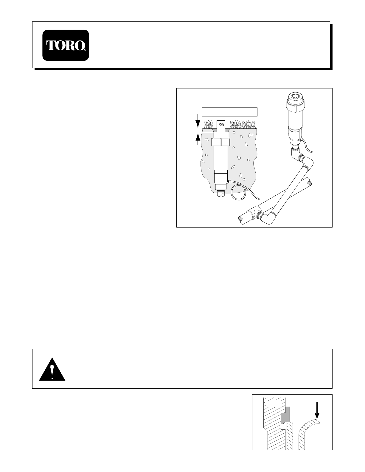
1. Construct triple swing joints for each sprinkler as shown
in Figure 1. Use PVC or ABS pipe nipple for sprinkler
connection.
Note: On sites where the possibility of heavy equipment
rolling over a sprinkler exists, the swing joint will flex
preventing damage to the lateral or main lines. On a new
installation in raw ground where the sprinklers are to be
initially installed above the finished grade and lowered
when new turf is established, the swing joint allows
sprinkler repositioning without changing risers. This is a
common and practical procedure which eliminates the
problem of dirt being accidentally introduced into the
lateral lines when a riser is changed.
2. Flush lines thoroughly prior to installing sprinkler.
3. Apply Teflon
™
tape on riser threads. Install sprinkler to
riser and tighten.
CAUTION
Use only Teflon tape on riser threads. Use of pipe dope or other types of sealing compounds can
cause deterioration of plastic threads and components.
4. Install sprinkler on riser. Align part-circle heads by rotating sprinkler body on riser until radius adjustment slot on top of the nozzle
rubber cover is positioned to the left side of the intended coverage area.
5. Valve-In-head models only: Remove tube retainer and cap from sprinkler fitting. Provide a service loop in control tube at
sprinkler to prevent binding. Slide tube retainer over end of control tube. Push control tube onto sprinkler fitting and secure with
tube retainer.
6. Install sprinklers flush with grade to 1/2 in. (0–13mm) below grade.
7. Backfill and compact soil around sprinkler avoiding contact with nozzle assembly.
Servicing the Sprinkler
Valve Replacement
WARNING
POSITIVELY SHUT OFF WATER SUPPLY AT SOURCE PRIOR TO DISASSEMBLING SPRINKLER.
BLEED ALL PRESSURE FROM SPRINKLER SYSTEM INCLUDING CONTROL TUBES. FAILURE TO
DEPRESSURIZE SYSTEM PRIOR TO VALVE SNAP RING REMOVALMAY CAUSE VALVE MECHANISM
TO FORCIBLY EJECT FROM SPRINKLER BODY RESULTING IN POSSIBLE SERIOUS INJURY.
1. Remove cap set screw with 1/8 in. hex wrench and unscrew cap.
2. Remove nozzle container seal, nozzle retainer and nozzle/drive assembly from body.
3. Depress valve mechanism using a long screwdriver or similar tool (see CAUTION below).
CAUTION
Do not continue valve removal procedure if the valve cannot be pressed
down with minimum force. Confirm that water pressure is off and the
control tube is bled before continuing.
1
Installation and Service Instructions
640 Series Rotary Sprinkler
0 in.–1/2 in. (0–13mm)
FIGURE 1
Body
Snap
Ring
Valve
Page 2
4. With the valve depressed, grasp snap ring "ears" with TORO snap ring pliers
(Model No. 995-07), release snap ring from groove and remove from body.
5. Remove valve mechanism with TORO Valve Removal Tool (Model No. 995-08) or
carefully grasp one valve rib with snap ring pliers, pulling valve up and out of body.
6. Reassemble valve mechanism in reverse order.
Note: Due to limited work space in 640 sprinklers, use of Toro Valve Insertion Tool
(Model No. 995-35) is recommended to simplify valve and snap ring installation.
7. See Reinstalling Nozzle/Drive Assembly.
Changing Nozzle and Stator
Note: Nozzle changes may be accomplished by
changing the entire nozzle assembly or by removing
the nozzle container end changing only the upper
nozzle. In either case, the appropriate matching
stator must be installed (i.e., No. 42 Nozzle and No.
42 Stator, etc.) to ensure proper sprinkler operation.
Changing Complete Nozzle Assembly
1. Remove cap set screw with 1/3 in. hex wrench and
unscrew cap.
2. Remove nozzle container seal, nozzle retainer and
nozzle/drive assembly from body.
3. Remove 1/16 in. allen set screw in side of nozzle
canister.
4. Unscrew nozzle assembly from drive assembly.
5. Assure nozzle seal is located at bottom of nozzle
base threads.
6. Install new nozzle assembly — HAND-TIGHTEN
ONLY, DO NOT OVER-TORQUE.
7. Turn set screw clockwise until contact with riser
threads is made (see CAUTION below).
CAUTION
Do not over-torque set screw. Over-tightening
will cause thread damage and possible water
leak between lower nozzle base and drive
assembly.
8. Remove boss on nozzle rubber cover to identify drive
assembly arc.
2
FIGURE 2
Body
Valve
Set Screw
Drive
Assembly
Nozzle
Assembly
Snap
Ring
Page 3

Changing Upper Nozzle
Note: Some of the nozzle assembly components
shown in the following procedure are no longer
available from Toro as service parts. This procedure
should only be used if the upper nozzle assembly is
already on hand.
1. Remove cap set screw with 1/8 in. hex wrench and
unscrew cap.
2. Remove nozzle container seal, nozzle retainer and
nozzle/drive assembly from body.
3. Straighten locking tabs on nozzle container with
nozzle container removal tool, Model No. 995-42 or
other appropriate tool (see Figure 3).
4. Remove nozzle container, nozzle screws and upper
nozzle assembly (see Figure 4).
5. Position new upper nozzle assembly and secure with
nozzle screws. DO NOT OVER-TIGHTEN
SCREWS. (See Figure 4 and Note below.)
Note: Over-tightening nozzle screws will expand
plastic nozzle base causing difficult nozzle container
replacement.
6. Align nozzle opening in container with nozzle orifices and press container downward until fully seated on nozzle assembly.
7. Bend locking tabs into notches approximately 90° to secure nozzle container.
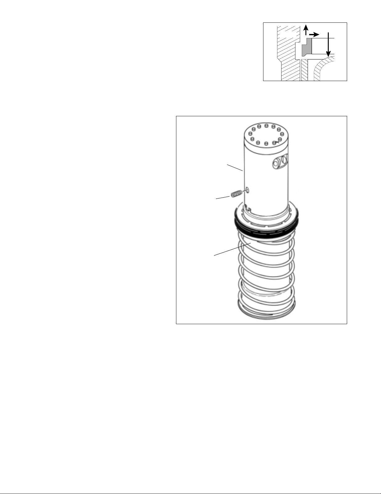
Changing Stator
1. Place nozzle/drive assembly on a flat
work surface, nozzle down, and
compress return spring to expose
stator assembly (see Figure 5).
2. Separate stator from drive assembly
(held together by press fit) and
CAREFULLY relieve return spring
tension.
3. Press in new stator assembly to fully
seated position.
3
FIGURE 3
FIGURE 4 FIGURE 5
Container
Removal Tool
995-42
Upper
Nozzle
Assembly
Lower
Nozzle
Assembly
Stator
Assembly
Page 4

Reinstalling Nozzle/Drive Assembly
1. Part Circle Only: Holding drive assembly stationary, slowly rotate nozzle assembly counterclockwise to left side of arc pattern
(see Figure 6).
2. Check drive assembly key tab for approximately 30° upward bend, adjust if necessary (see Figure 7).
3. Insert nozzle/drive assembly into body until seal is approximately one (1) inch below top of body.
Part Circle Only: Align main nozzle orifice with left edge of watering arc before inserting (see Figure 8).
4. Place nozzle retainer over nozzle assembly aligning keyway and drive assembly key (see Figure 9).
5. Rotate nozzle retainer, interlocked
with nozzle/drive assembly, to align
the nearest of six (6) alignment slots
with tabs on body (see Figure 10).
6. Press retainer into body to interlock
alignment slot and body tab.
7. Install riser seal over nozzle
assembly placing peg into retainer
keyway (see Figure 11).
8. Install cap and secure with set
screw.
9. Check watering arc. If minor
adjustments are required (1/6 of a
turn or less); rotate sprinkler body
on riser. Do not make adjustments
by turning nozzle assembly (see
CAUTION below).
CAUTION
Rotating nozzle assembly to
make watering arc adjustments
may cause severe internal
damage to drive assembly.
Note: Refer to Illustrated Parts
Breakout Book Form No. 368-0044
for current parts listing.
4
© 1998 THE TORO COMPANY
Irrigation Division • An ISO 9001-Certified Facility
PRINTING DATE P.O. Box 489 • Riverside, CA 92502 PART NO.
FEBRUARY 1998 REV. E Printed in U.S.A. 362-0052
FIGURE 6 FIGURE 7
FIGURE 9
FIGURE 10 FIGURE 11
FIGURE 8
Rotate
Counterclockwise
Drive
Assembly Key
Nozzle Retainer
Keyway
(Shaded Area)
Nozzle Retainer
Keyway
Body
Tab
Alignment Slots
Riser
Seal Peg
Nozzle
Retainer
Keyway
Drive
Assembly
Key
1"
 Loading...