

Page 1

A-31 ENGINE SERVICE MANUAL
Table of Contents – Page 1 of 1
GENERAL INFORMATION
GENERAL SPECIFICAT IO NS
TORQUE SPECIFICATIONS
SAFETY WARNINGS AND NOTES
OPERATION AND MAINTENANCE
TROUBLESHOOTING
ENGINE FAILS TO START
ENGINE STARVES ON ACCELERATION
ENGINE IS HARD TO START
ENGINE STALLS
ENGINE FIRES INTERMITTENTLY
ENGINE DOES NOT PRODUCE MAXIMUM POWER
CARBURETOR FLOODS
ENGINE STOPS AFTER RUNNING BRIEFLY
ENGINE WILL NOT IDLE
ENGINE BACKFIRES OR MISFIRES
ENGINE WILL NOT ACCELERATE
ENGINE LACKS POWER OR STOPS DURING OPERATION
DISASSEMBLY, INSPECTION, & REPAIR
TYPICAL DISASSEMBLY SEQUENCE
DISASSEMBLE MAJOR COMPONENTS
DISASSEMBLE ENG IN E
REASSEMBLY
TYPICAL ASSEMBL Y SEQU E NCE
ENGINE REASSEMBLY
INSTALL MAJOR COMPONENTS
Page 2

GENERAL INFORMATION
General Information .........................
Troubleshooting ............................
Disassembly, Inspection and Repair .................
Reassembly ..............................
1
2
3
4
1-1
Page 3

GENERAL INFORMATION
1
General Specifications ...............1-3
Engine ......................1-3
Fuel And Lubrication ...............1-3
Ignition ......................1-3
Torque Specifications ................1-4
Air Filter ......................1-4
Carburetor ....................1-4
Carburetor Mount/Reed Plate ..........1-4
Table Of Contents
Clutch .......................1-4
Crankcase And Cylinder .............1-5
Flex Drive Housing (Boom) ............1-5
Flywheel .....................1-5
Ignition Module ..................1-5
Ignition Switch ..................1-6
Muffler ......................1-6
Starter/Starter Housing ..............1-6
Safety Warnings and Notes .............1-7
Operation and Maintenance .............1-8
Product Identification Numbers ..........1-8
Fuel Recommendations .............1-8
Fuel and Oil Mixing Instructions .........1-9
1-2
Starting/Stopping Instructions ..........1-9
Service/Maintenance Instructions ........1-11
Storage Instructions ...............1-14
Special Tools ...................1-15
Page 4

General Specifications
GENERAL INFORMATION
Engine
Item
Engine Type Air-cooled, 2-Cycle
Displacement 1.9 cu. in. (31 cc)
Bore 1.37 in. (34.80 mm)
Stroke 1.25 in. (31.75 mm)
Average Compression 90-120 lbs. (41-55 kg)
Piston Ring Width 0.046 in. (1.16 mm)
Piston Ring End Gap 0.085 in. (2.159 mm)
Piston Ring Side Clearance 0.005 in. max (0.127 mm)
1
Fuel And Lubrication
Item
Lubrication Fuel/Oil Mixture
Fuel/Oil Ratio 32:1
Approx. Fuel Tank Capacity 18 oz (530 ml)
Ignition
Item
Ignition Type C.D. Electronic Ignition
Ignition Module Air Gap 0.010-0.015 in. (0.254-0.381 mm)
Spark Plug Type Champion® DJ8J
Spark Plug Gap 0.025 in (0.635 mm)
1-3
Page 5

GENERAL INFORMATION
Torque Specifications
Air Filter
1
Item
Air Filter Cover Mounting Screws 15-25 in•lb (1.7-2.8 N•m)
Carburetor
Item
Carburetor/Choke Plate Mounting Screws 35-40 in•lb (3.9-4.5 N•m)
Throttle Wire Swivel Screw 9-12 in•lb (1.0-1.4 N•m)
Carburetor Mount/Reed Plate
Item
Carburetor Mount/Reed Plate Mounting Screws 60-65 in•lb (6.8-7.3 N•m)
Reed Valve/Reed Backup Plate Mounting Screw(s) 15-20 in•lb (1.7-2.3 N•m)
Clutch
Item
Clutch Cover Mounting Screws 35-40 in•lb (3.9-4.5 N•m)
Clutch Drum Screw 38-44 in•lb (4.3-5.0 N•m)
Clutch Rotor 150-160 in•lb (16.9-18 N•m)
1-4
Page 6

GENERAL INFORMATION
Crankcase And Cylinder
Item
Crankcase (Cylinder) Mounting Screws 110-120 in•lb (12.4-13.5 N•m)
Crankcase Cover Mounting Screws 67 in•lb (7.5 N•m)
Fan Shroud Mounting Screws 110-120 in•lb (12.4-13.5 N•m)
Spark Plug 190-210 in•lb (21.4-23.6 N•m)
Flex Drive Housing (Boom)
Item
1
Boom Clamp Nut 70-80 in•lb (7.9-9.0 N•m)
Anti-rotation Screw 15-20 in•lb (1.7-2.3 N•m)
Flywheel
Item
Flywheel Mounting/Square Drive Nut (Non-clutch Models) 150-160 in•lb (16.9-18 N•m)
Flywheel Mounting/Crankshaft Extension Nut (Blowers) 150-160 in•lb (16.9-18 N•m)
Ignition Module
Item
Ignition Module Mounting Screws 28-35 in•lb (3.2-3.9 N•m)
1-5
Page 7

GENERAL INFORMATION
Ignition Switch
Item
1
Slide Switch Contact To Switch Cover Screw 7-12 in•lb (0.8-1.4 N•m)
Slide Switch Contact To Starter Housing Screw 10-15 in•lb (1.1-1.7 N•m)
Stop Switch Lead To Starter Housing Screw 10-15 in•lb (1.1-1.7 N•m)
Toggle Switch Nut 25-35 in•lb (2.8-3.9 N•m)
Muffler
Item
Muffler Exhaust Tube Screws 15-25 in•lb (1.7-2.8 N•m)
Muffler Heat Shield Screw 15-25 in•lb (1.7-2.8 N•m)
Muffler Mounting Screws
Serial Numbers Prior to 809000000 56 in•lb (6.3 N•m)
Serial Number 809000000 and Greater 80-90 in•lb (9.0-10.1 N•m)
Starter/Starter Housing
Item
Shroud Extension/Engine Stand Screw 25-35 in•lb (2.8-3.9 N•m)
Starter Housing Screws 35-40 in•lb (4.1-4.5 N•m)
Starter Pulley Retainer Screw(s) 20-30 in•lb (2.3-3.4 N•m)
Handle Bracket Screws (Cultivators) 35-40 in•lb (4.1-4.5 N•m)
1-6
Page 8

GENERAL INFORMATION
SAFETY WARNINGS AND NOTES
The purpose of safety symbols is to attract your
attention to possible dangers. The safety symbols and
the explanations with them, deserve your careful
attention and understanding. The safety warnings do
not by themselves eliminate any danger. The
instructions or warnings they give are not substitutes
for proper accident prevention measures.
WARNING: For Your Safety!
Highlights instructions which failure to obey can result
in personal injury.
NOTE: Advises of information which maybe useful while performing maintenance or repair of the
equipment. Also highlights instructions which failure to obey can result in damage to parts or equipment.
WARNING: Spring Under Tension!
WARNING: Explosive Fuel!
Gasoline may be present in the fuel tank, carburetor,
fuel lines, or crankcase. Gasoline is extremely flammable and its vapors can explode if ignited. Keep
sparks, flames, and other sources of ignition away
from the engine. Do not smoke while servicing the
engine. Never use gasoline as a cleaning agent.
Store gasoline only in approved containers, in wellventilated, unoccupied buildings, away from sparks,
flames, or other sources of ignition. Do not fill the fuel
tank while the engine is hot or running, since spilled
fuel could ignite if it comes in contact with hot parts or
sparks from ignition. Do not start the engine near
spilled fuel. Do not smoke while handling gasoline or
filling the fuel tank.
WARNING: Cracked or Broken Cooling Fins
Are A Hazard!
Be careful not to crack or break any cooling fins. They
could fly off during operation. If cooling fins are
cracked or broken, replace the flywheel.
1
The rope starter on these engines contains a flat wire
spring that is under tension. Wear eye and hand
protection when replacing worn or broken spring, in
case it should uncoil as it is handled. Allow spring
tension to be completely relieved and make sure
pulley disengages from spring before removing the
pulley retainer(s), pulley, andstarter spring from
housing.
WARNING: Electrical Shock!
Never touch electrical wires or components while the
engine is running. They can be sources of electrical
shock.
WARNING: Hot Surfaces!
The muffler, cylinder, crankcase, trimmer cutting head,
and other engine surfaces get extremely hot from
operation. These surfaces remain hot for a short
period of time after the engine is stopped. To prevent
severe burns, allow the engine to cool completely
before servicing.
1-7
Page 9
GENERAL INFORMATION
OPERATION AND MAINTENANCE
1
PRODUCT IDENTIFICATION
NUMBERS
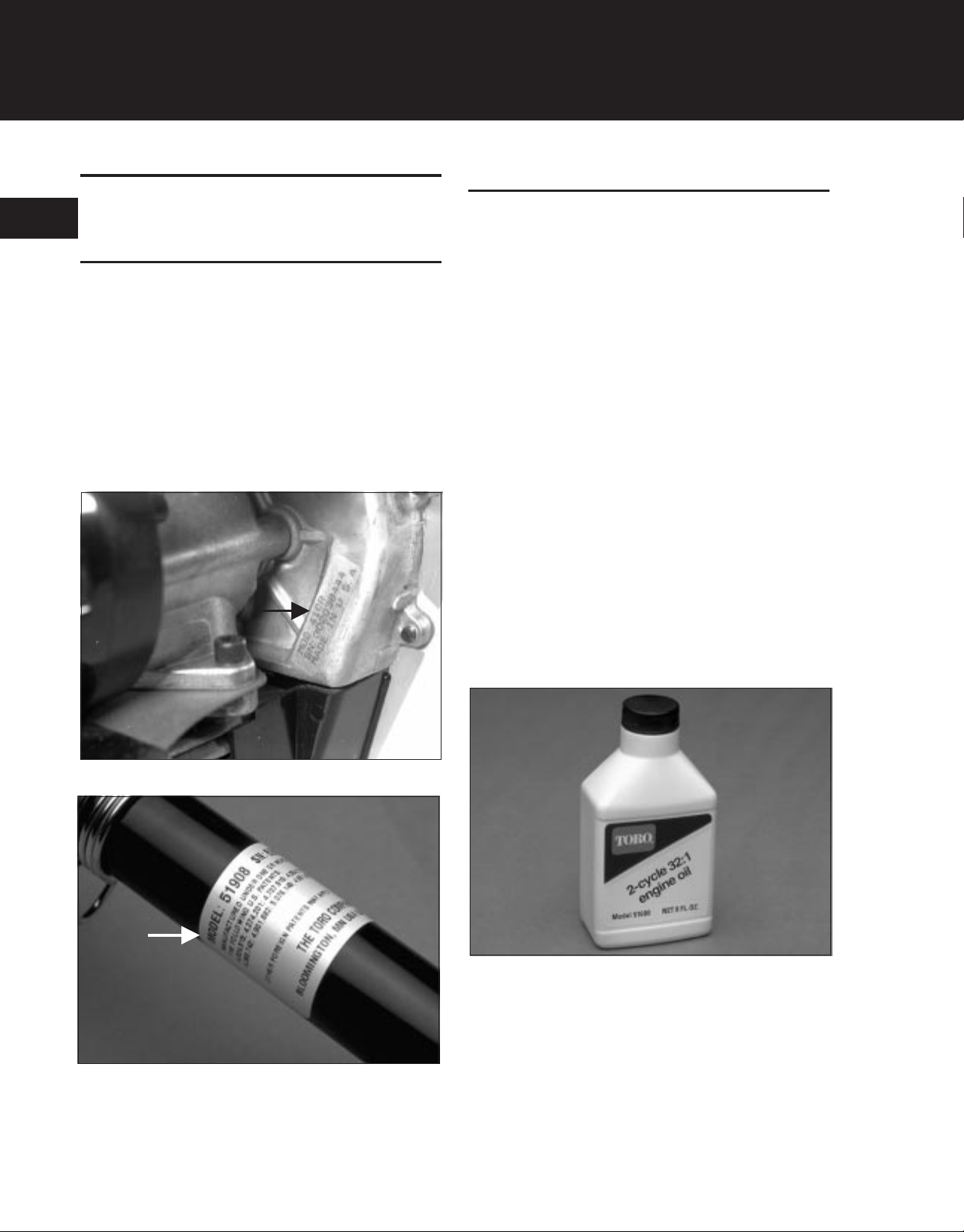
When ordering parts, or in any communication involving an engine or product, always give the:
• Model Number, and
• Serial Number
These numbers are located on a decal (or decals) affixed to the unit (Figure 1-1). The identification decal(s) will be located on the engine, metal boom, or
plastic housing. The actual location will vary depending on the type of product.
Fuel Recommendations
WARNING: Explosive Fuel!
Gasoline is extremely flammable and its vapors can
explode if ignited. Store gasoline only in approved
containers, in well-ventilated, unoccupied buildings,
away from sparks or flames. Do not fill the fuel tank
while the engine is hot or running, since spilled fuel
could ignite if it comes in contact with hot parts or
sparks from ignition. Do not start the engine near
spilled fuel. Do not smoke while handling gasoline.
Never use gasoline as a cleaning agent.
NOTE: READ THESE INSTRUCTIONS CAREFULLY BEFORE ATTEMPTING TO START OR
OPERATE THIS UNIT. Using old oil or fuel, or improperly mixing the oil and fuel can cause engine
damage. This type of damage will void the engine
warranty.
Recommended Oil Type
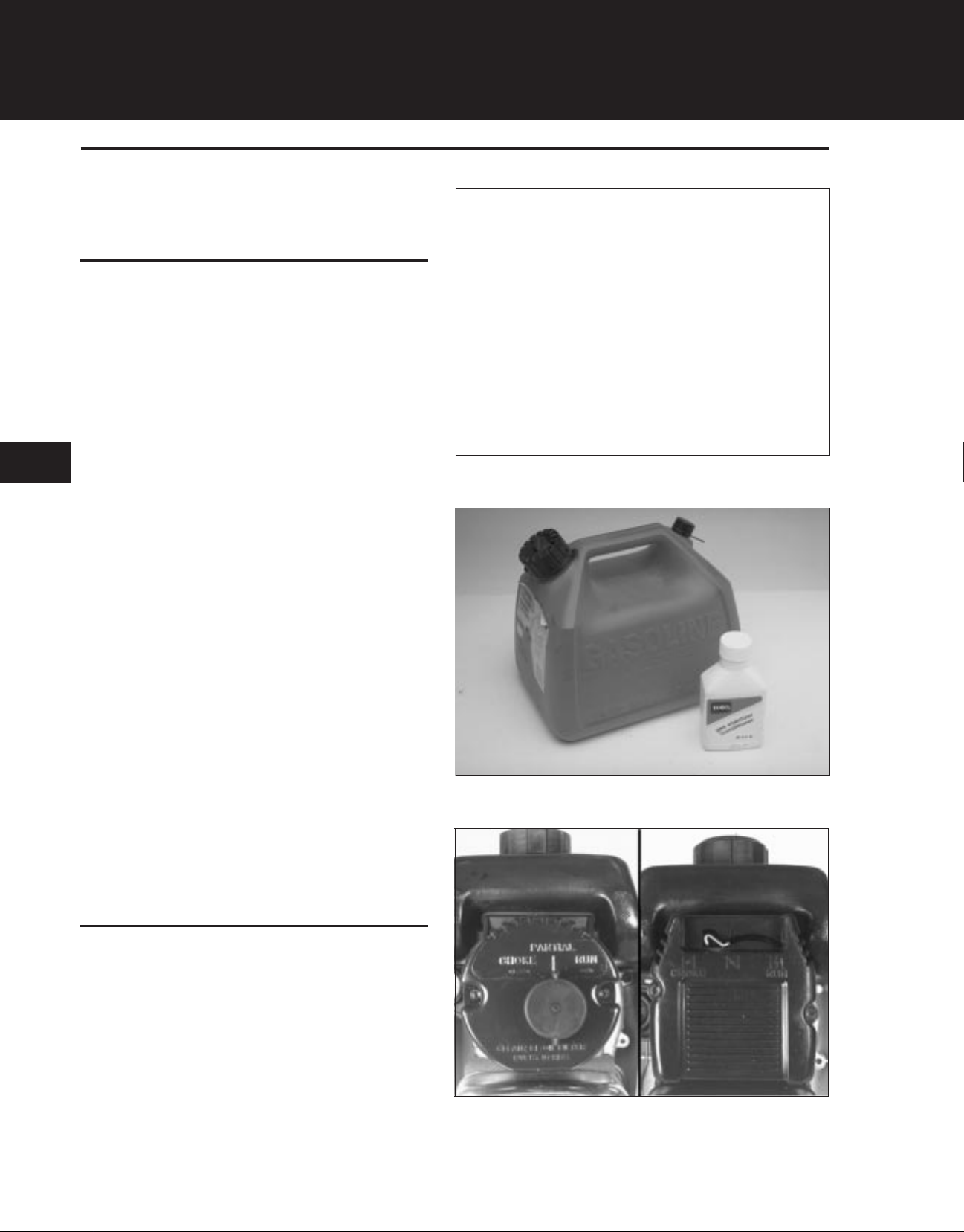
Figure 1-1A. Product Identification Plate.
Toro 2-cycle oil is recommended for use in these engines (Figure 1-2). If another brand of 2-cycle oil is
used, use a high quality oil that is formulated for small
2-cycle air-cooled engines.
2.6078.001
Figure1-2. Recommended Oil Type.
Recommended Fuel Type
Use clean, fresh, regular grade unleaded gasoline.
Figure 1-1B. Product Identification Plate.
1-8
1.0762.005
NOTE: Alcohol blended fuel absorbs moisture
(water). As little as 1% moisture in the fuel can cause
fuel and oil to separate and form acids when stored.
Page 10

GENERAL INFORMATION
If these types of fuel must be used, use fresh fuel (less
than 60 days old) and mix according to the instructions
in this section.
Use Of Blended Fuels
If you choose to use a blended fuel or its use is
unavoidable, the following precautions are
recommended.
1. Always use fresh fuel mixed according to the
instructions in this section.
2. Use the special additive Alcohol Protector®
(by Gold Eagle) or equivalent to inhibit corrosion
and reduce oil/fuel separation (mix as directed).
3. Always agitate the fuel mix before fueling unit.
4. Drain the fuel tank and run engine dry before
storing unit.
oz. (11 ml) per gallon of gasoline or mix per instructions on container. NEVER add fuel additives directly
to the unit fuel tank.
Fuel And Oil Mixing Instructions
NOTE: For proper engine operation and maximum re-
liability, pay strict attention to these fuel and oil mixing
instructions. Use a 32:1 fuel/oil ratio when using Toro
2-cycle oil. Using improperly mixed fuel can severely
damage the engine. Never mix the gasoline and oil in
the fuel tank of the unit.
Use the following procedures to ensure complete mixing:
1. Put a small amount of fresh gasoline into a clean 1
U.S. gallon (3.785 liter) fuel can.
2. Add 4-oz. (118 ml) of Toro 2-cycle engine oil.
3. Fill the remainder of the fuel can with gasoline.
1
Problems With Blended Fuels
Some problems associated with blended fuels include:
• Vapor lock
• Poor warm restart
• Poor performance at high altitudes
• Corrosion of fuel system components
If any of these symptoms occur, switch to regular, unleaded gasoline.
Gasohol Use May Require Carburetor Adjustments
These engines are lubricated by oil mixed with fuel.
Using blended fuel may alter the air/fuel ratio causing
a lean mix (less fuel, more air).
If this condition is not corrected by adjusting the carburetor, engine damage due to poor lubrication can result.
Use Of Fuel Additives
4. Screw the fuel can cap on tightly and SHAKE THE
CAN VIGOROUSLY FOR 30 SECONDS.
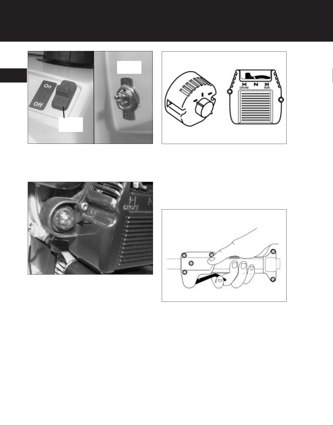
Starting/Stopping Instructions
To Start The Engine
1. If the unit is equipped with an ignition switch, make
sure the switch is in the “START” or “ON” position
(Figure 1-3).
The use of fuel additives such as Toro Gas Conditioner/Stabilizer or an equivalent, will minimize the formation of fuel gum deposits. Such an additive should
only be used when fuel/oil mix is prepared. Add 0.4
1-9
Page 11
GENERAL INFORMATION
1
Slide
Switch
Toggle
Switch
Figure 1-3. Typical Ignition Switches.
2. If the unit is equipped with a primer bulb, FULLY
PRESS AND RELEASE the primer bulb 5 to 7
times (Figure 1-4).
Figure 1-4. Primer Bulb.
2.6078.003
2.6078.004
Figure 1-5. Typical Choke Controls.
4. Place the unit in the starting position (with the trimmer cutting head, cultivator tines, or blower nozzle
away from yourself and others).
5. Squeeze the throttle trigger to “FULL THROTTLE”
(Figure 1-6). Hold or lock the throttle in this position.
3.6078.005
3. Place the choke knob or choke lever in the FULL
“CHOKE” position (Figure 1-5).
1-10
Figure 1-6. Typical Throttle Control.
6. Pull the starter rope BRISKLY until you hear the engine sound like it wants to run (normally 2 to 5
pulls).
7. Place the choke knob or choke lever in the “PARTIAL” choke position (Figure 1-5).
8. Pull the starter rope BRISKLY 1 to 3 pulls to start
the engine.
3.6078.006
Page 12
9. If the engine does not start, repeat steps 1 to 8.
GENERAL INFORMATION
10. After the engine warms up for 5 to 10 seconds,
place the choke knob or choke lever in the “RUN”
position.
To Stop The Engine
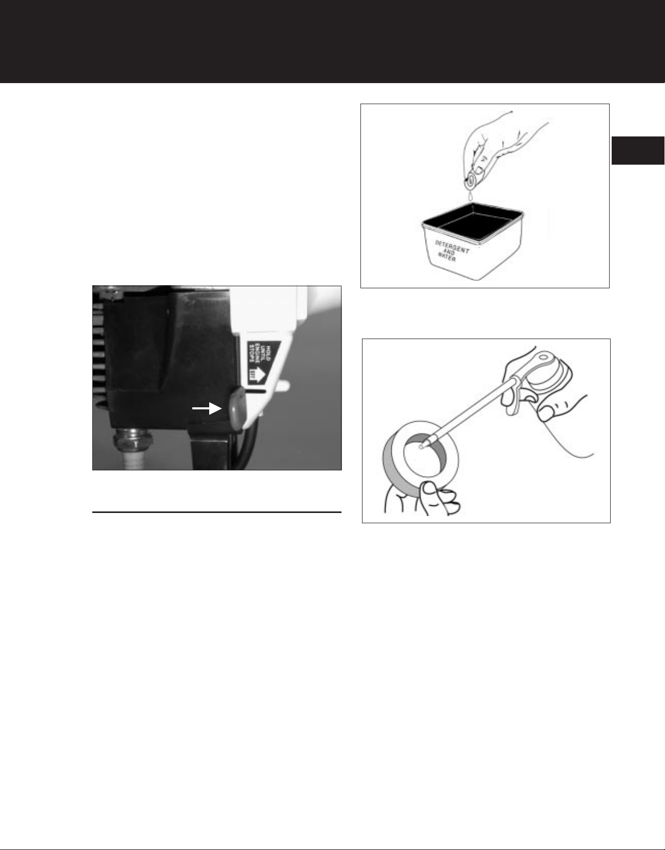
Place the ignition switch in the “OFF” or “STOP” position. For those units with a momentary (or push-tostop) type switch, push and hold the button or lever
until the engine stops completely (Figure 1-7).
Figure 1-8. Washing Air Filter Element.
3. Apply clean SAE 30 oil to the air filter (Figure 1-9).
3.6078.008
1
Figure 1-7. Typical Stop Button.
Service/Maintenance Instructions
Air Filter
NOTE: CLEAN AND RE-OIL THE AIR FILTER
EVERY 10 HOURS OF OPERATION. The air filter is
one of the most important areas to maintain. If it is not
maintained as follows, severe engine damage can
result.
1. Remove the air filter from the carburetor/air filter
cover assembly. Refer to Part 3 - Engine Disassembly.
2. Wash the air filter in detergent and water (Figure 1-
8). Rinse the air filter thoroughly in clean water
and allow it to dry.
2.6078.007
Figure 1-9. Oiling Air Filter Element.
4. Squeeze the air filter to ensure that the oil is spread
throughout the entire filter (Figure 1-10).
3.6078.009
1-11
Page 13
GENERAL INFORMATION
1
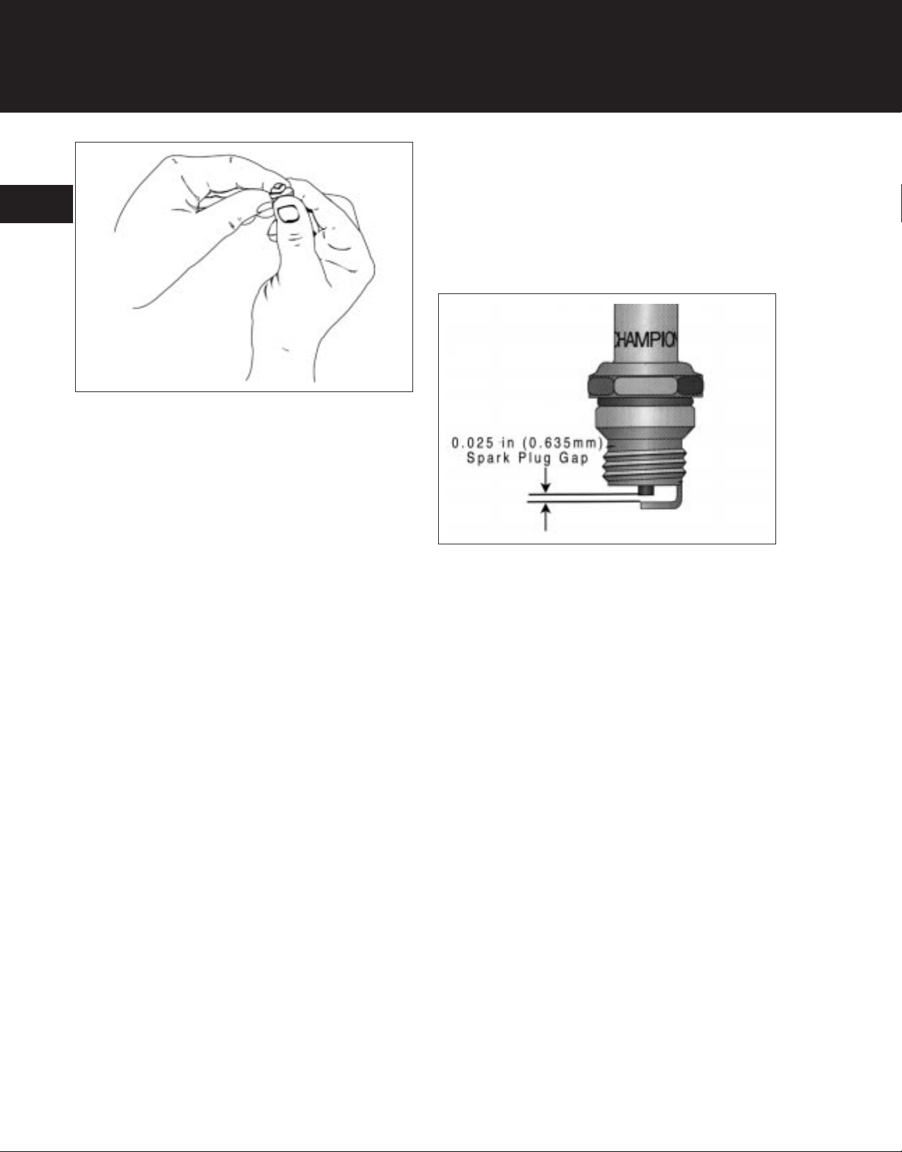
4. Check the spark plug gap using a wire feeler gauge.
Set the gap to 0.025 inch (0.635 mm) (Figure 1-
11).
5. Reinstall the spark plug and torque to 190-210 in•lb
(21.4-23.6 N•m).
Figure 1-10. Squeezing Excess Oil From Air
Filter Element.
5. Reinstall the air filter in the carburetor/air filter
cover assembly. Refer to Part 4 - Engine Assembly.
Spark Plug
Every 50 hours of operation, remove the spark plug,
check its condition, and reset the gap or replace with a
new plug as necessary.
WARNING: Electrical Shock!
Never touch electrical wires or components while the
engine is running. They can be sources of electrical
shock.
1. Before removing the spark plug, clean the area
around the base of the spark plug to keep dirt and
debris out of the engine.
2. Disconnect the spark plug wire and remove the
spark plug from engine.
3.6078.010
Figure 1-11. Spark Plug Gap.
Carburetor Adjustment
These engines are equipped with a diaphragm-type
carburetor. The carburetor has been carefully calibrated at the factory. In most cases, no further adjustment will be required.
The condition of the air filter is very important to the operation of the trimmer. A dirty air filter will restrict the
air flow to the carburetor. This in turn upsets the fuelair mixture in the carburetor. The resulting symptoms
are often mistaken for an out-of-adjustment carburetor.
Therefore, check the condition of the air filter before
adjusting the carburetor. Refer to “Air Filter” Service/Maintenance Instructions.
If the following conditions are experienced, it may be
necessary to adjust the carburetor.
2.6081.011
3. Inspect the spark plug for carbon buildup and clean
if necessary. Replace the plug if it is badly burnt or
if reuse is questionable.
NOTE: Do not clean the spark plug in a machine
which uses abrasive grit. Some grit could remain
on the spark plug and enter the engine causing
extensive damage.
1-12
• The engine will not idle.
• The engine hesitates or stalls on acceleration.
• The loss of engine power, which is not corrected
by cleaning the air filter.
• The engine operates in an erratic or fuel-rich
condition (indicated by excessive exhaust smoke
from the muffler).
Page 14
GENERAL INFORMATION
NOTE: Follow these carburetor adjustment proce-
dures carefully. An incorrectly adjusted carburetor can
cause severe engine damage.
Make sure the unit is fully assembled before making
carburetor adjustments:
For trimmers and brush cutters, make sure the boom,
cutting head, and line guard are installed and the cutting line is extended to its full cutting length.
For cultivators, make sure the boom and gear box are
installed.
For blowers and blower-vacs, make sure the blower
tube and nozzle are installed.
The carburetor has three basic adjustments: the idle
speed adjustment, the idle mixture adjustment, and
the high speed mixture adjustment (Figure 1-12).
(H) High Speed
Mixture Needle
(L) Idle
Mixture Needle
needles clockwise until they are lightly seated.
Then turn the needles counterclockwise the following number of turns:
1
High Speed Mixture Needle:1-1/4 turns
Idle Mixture Needle: 1-1/4 turns
NOTE: Turn the high speed mixture and idle mixture needles finger-tight. Do not force the needles
with a screwdriver as this can damage the tips of
the needles and the seats in the carburetor body.
5. Start engine and allow it to warm up for 3 to 5 minutes.
NOTE: For the following steps, use a magnetic
pick-up 2-cycle engine tachometer to monitor engine speed.
Idle Speed
Figure 1-12. Carburetor Adjustments.
3.6081.012
1. Remove air filter cover assembly as instructed in
Part 3 — Engine Disassembly.
2. Initial Idle Speed Setting: Turn idle speed screw
counterclockwise until it does not touch the throttle
lever. Now turn the screw clockwise until it just
touches the throttle lever; then continue turning 2
full turns.
3. If so equipped, remove the rubber cap from the high
speed mixture adjustment needle.
4. Initial High Speed Mixture and Idle Mixture Settings:
Turn both the high speed mixture and idle mixture
6. Final High Speed Mixture Setting: Squeeze the throttle trigger to the FULL (WIDE OPEN) THROTTLE
position. Turn the high speed mixture needle clockwise or counterclockwise to set the high speed
RPM:
Trimmers and Cultivators: 6,800 to 7,200 RPM
Blowers and Blower-Vacs: 6,600 to 7,200 RPM
7. Release the throttle trigger and let the engine idle. If
the engine stops, turn the idle speed screw clockwise 1/8 turn at a time until the engine idles.
8. Final Idle Mixture and Idle Speed Settings: Adjust
the the idle mixture and idle speed as follows:
a. Turn the idle mixture needle clockwise until the
fastest idle RPM is reached; then turn the needle counterclockwise 1/8 turn.
b. Squeeze the throttle trigger. If the engine falters
or hesitates as it accelerates, turn the idle mixture needle counterclockwise 1/16 turn at a
time until the engine accelerates rapidly.
1-13
Page 15

GENERAL INFORMATION
c. If the idle speed has changed significantly be-
cause of steps a. and b. above, readjust the
idle speed screw.
1
The recommended idle speed for all products
is 3,000 to 3,200 RPM.
9. Stop the engine. Install the air filter and restart the
engine. Recheck the operation and readjust as
necessary.
10. Make sure the air filter cover is reinstalled securely
before placing the unit back into service.
Governed Carburetor Check
Some units are equipped with fuel-governed carburetors. If so equipped, and after adjusting the carburetor,
check the operation of the governor on trimmers and
brush cutters as follows:
1. Clip or wind the cutting line so it is inside the
cutting head (not extended to its full cutting length).
Do not smoke while handling gasoline. Never use
gasoline as a cleaning agent.
Storage For 45 To 60 Days
Use the following storage procedure for equipment or
fuel that will be stored for more than 45 days and less
than 60 days:
Equipment - Empty the fuel tank and run the unit until
the fuel system is empty. When starting the unit after
storage, refill the fuel tank with freshly mixed gasoline
and oil.
Fuel - Do not use fuel that has been stored for more
than 60 days. Dispose of the old fuel in a safe manner
and use a fresh mix.
Storage For More Than 60 days
1. Drain all fuel from the fuel tank into an approved
fuel container.
2. Start the engine and run it until it stalls.
2. Start the engine and run it at FULL (WIDE OPEN)
THROTTLE.
The maximum high speed RPM should not exceed 8,800 RPM.
3. If the high speed RPM exceeds 8,800 RPM, the
governor assembly in the carburetor must be
cleaned or replaced and the carburetor readjusted.
Storage Instructions
WARNING: Explosive Fuel!
Gasoline is extremely flammable and its vapors can
explode if ignited. Store gasoline only in approved containers, in well-ventilated, unoccupied buildings, away
from sparks or flames. Do not fill the fuel tank while
the engine is hot or running, since spilled fuel could ignite if it comes in contact with hot parts or sparks from
ignition. Do not start the engine near spilled fuel.
3. Allow the engine to cool. Remove the spark plug
and put about 1 oz. (39 ml) of any high quality motor or 2-cycle oil into the cylinder. Pull the starter
rope slowly to distribute the oil. Reinstall the spark
plug.
4. Clean the unit and inspect for any loose or
damaged parts. Repair or replace damaged parts
and tighten loose screws, nuts, or bolts.
5. Store the unit in a dry, well ventilated area.
To Reactivate Unit For Service
1. Remove the spark plug and drain the oil from the
cylinder by slowly pulling the starter rope.
2. Reinstall the spark plug.
3. Refuel the unit with a fresh gasoline /oil mixture.
Start engine in accordance with the Starting Instructions.
1-14
Page 16
Special Tools
GENERAL INFORMATION
In addition to typical hand tools, the following special
tools are required to properly service these engines:
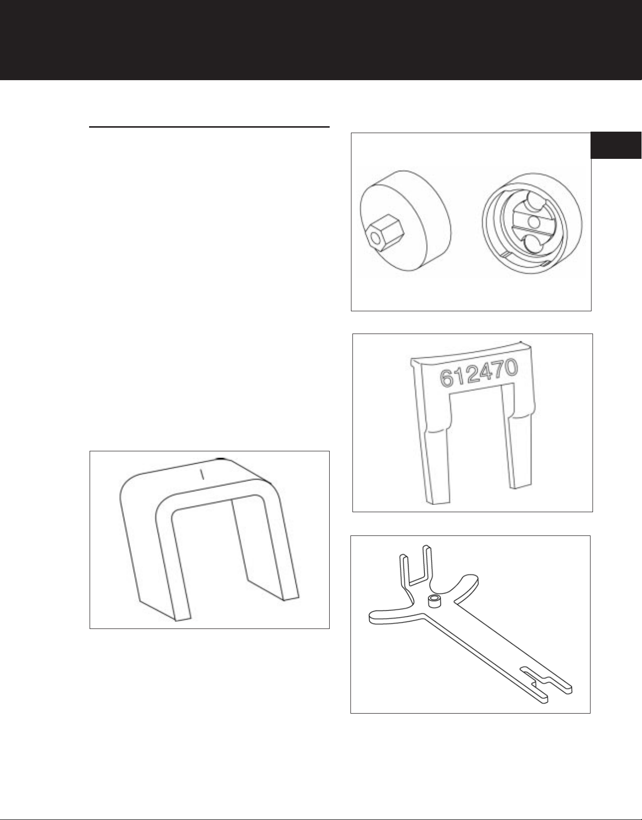
• Clutch Tool, P/N 147337 (Figure 1- 13) or P/N
180918 (Figure 1-14).
• Flywheel Holder, P/N 612470(Figure 1-15) or P/N
180919(Figure 1-16).
• Flywheel Strap Wrench or Spanner Wrench
(Commercially available).
• 0-250 in•lb (0-28.1 N•m) Torque Wrench
(Commercially available).
• Torx® Screwdriver or Bit Set (Commercially
available).
• Two-stroke, Magnetic Pick-up Tachometer
(Commercially available).
• Arbor or Hydraulic Press (Commercially
available).
• Bearing And Seal Pullers (Commercially
available).
Figure 1-14.Clutch Tool, P/N 180918.
1
3.6051.022
Figure 1-13. Clutch Tool, P/N 147337.
3.6069.011
Figure 1-15 Flywheel Holder, P/N 612470.
Figure 1-16 Flywheel Holder, P/N 180919.
3.6069.013
3.6051.023
1-15
Page 17

GENERAL INFORMATION
1
1-16
Page 18

TROUBLESHOOTING
General Information ..........................
Troubleshooting ...........................
Disassembly, Inspection and Repair .................
Reassembly ..............................
1
2
3
4
2-1
Page 19

TROUBLESHOOTING
Engine Fails To Start ................2-3
Engine Starves On Acceleration ..........2-4
Engine Is Hard To Start ...............2-4
2
Engine Stalls .....................2-5
Engine Fires Intermittently ..............2-5
Engine Does Not Produce Maximum Power ....2-6
Table Of Contents
Carburetor Floods ..................2-6
Engine Stops After Running Briefly .........2-7
Engine Will Not Idle .................2-7
Engine Backfires Or Misfires ............2-7
Engine Will Not Accelerate .............2-8
Engine Lacks Power Or Stops During Operation . . 2-8
2-2
Page 20

TROUBLESHOOTING
When difficulties occur, be sure to check for simple
causes which, at first, may seem too obvious to be
considered. A starting problem, for example, could be
caused by an empty fuel tank.
The following table lists some common causes of
operating troubles and the possible causes and
remedies.
Engine Fails To Start
Possible Cause Remedy
Ignition switch OFF Turn switch ON
Out of fuel or water in fuel Drain tank and blow out fuel lines to remove
water. Refuel tank with fresh fuel mixture.
Dirty or plugged air filter Clean or replace air filter
Loose spark plug lead wire Reconnect lead wire
Fouled, improperly gapped, or broken spark plug Clean or replace spark plug; set gap to
0.025 inch (0.635 mm)
2
Plugged fuel tank cap vent Clean fuel tank cap vent
Plugged or waterlogged fuel filter Replace fuel filter
Improperly adjusted carburetor Adjust carburetor
Plugged muffler Clean or replace muffler
Faulty primer or primer/fuel lines improperly installed Correctly install primer/fuel lines or replace
primer
Incorrect fuel mixture Drain tank; refill with correct fuel mixture
Plugged fuel line Blow out fuel line
Faulty carburetor diaphragm Replace diaphragm
Plugged fuel pump filter screen Clean or replace filter screen
Faulty fuel pump diaphragm Replace pump diaphragm
Plugged carburetor/fuel pump passages Clean out passages
Incorrect air gap between flywheel and Ignition module Set ignition module air gap to
0.010-0.015 in. (0.254-0.381 mm)
Faulty ignition module Replace ignition module
Faulty reed valve Replace reed valve
Low compression Replace piston ring or gasket
2-3
Page 21

TROUBLESHOOTING
Engine Starves On Acceleration
Possible Cause Remedy
Plugged fuel filter Replace fuel filter
Improperly adjusted carburetor Adjust carburetor about 1/8 turn
2
Engine Is Hard To Start
Possible Cause Remedy
Fouled, improperly gapped, or broken spark plug Clean or replace spark plug; set gap to
0.025 inch (0.635 mm)
Plugged or waterlogged fuel filter Replace fuel filter
Improperly adjusted carburetor Adjust carburetor
Clogged muffler Clean or replace muffler
Faulty primer or primer/fuel lines improperly installed Correctly install primer/fuel lines or
replace primer
Incorrect air gap between flywheel and ignition module Set ignition module air gap to
0.010-0.015 in. (0.254-0.381 mm)
Faulty ignition module Replace ignition module
Worn or improperly adjusted carburetor jet needle Adjust or replace needle
Faulty carburetor diaphragm Replace carburetor diaphragm
Faulty fuel pump diaphragm Replace fuel pump diaphragm
Faulty reed valve Replace reed valve
Low compression Replace piston ring or cylinder gasket
2-4
Page 22

TROUBLESHOOTING
Engine Stalls
Possible Cause Remedy
Dirty or plugged air filter Clean or replace air filter
Fouled, improperly gapped, or broken spark plug Clean or replace spark plug; set gap to
0.025 inch (0.635 mm)
Plugged fuel tank cap vent Clean fuel tank cap vent
Incorrect fuel mixture Drain tank; refill with correct fuel mixture
Improperly adjusted carburetor Adjust carburetor
Plugged muffler Clean or replace muffler
Plugged fuel line Blow out fuel line
Faulty ignition module Replace ignition module
Engine Fires Intermittently
Possible Cause Remedy
Fouled, improperly gapped, or broken spark plug Clean or replace spark plug; set gap to
0.025 inch (0.635 mm)
Incorrect air gap between flywheel and ignition module Set ignition module air gap to
0.010-0.015 in. (0.254-0.381 mm)
Faulty ignition module Replace ignition module
2
Incorrect fuel mixture Drain tank; refill with correct fuel mixture
2-5
Page 23

TROUBLESHOOTING
Engine Does Not Produce Maximum Power
Possible Cause Remedy
Plugged air filter Clean or replace air filter
Incorrect fuel mixture Drain tank; refill with correct fuel mixture
Plugged muffler Clean or replace muffler
Plugged or waterlogged fuel filter Replace fuel filter
2
Improperly adjusted carburetor Adjust carburetor
Leaking reed valve Replace reed valve
Air leak at carburetor base gasket Tighten carburetor fasteners or
replace carburetor base gasket
Intermittent spark Replace ignition module
Low compression Replace piston ring or cylinder gasket
Leaking crankcase seals Replace crankcase seals
Scored piston and/or cylinder Replace piston and cylinder assembly
Worn piston ring or low compression Overhaul engine
Carburetor Floods
Possible Cause Remedy
Faulty primer or improperly installed primer/fuel lines Correctly install primer/fuel lines
or replace primer
Improperly adjusted carburetor Adjust carburetor
Damaged carburetor Replace carburetor
Leaking fuel inlet needle Replace fuel inlet needle
2-6
Page 24

TROUBLESHOOTING
Engine Stops After Running Briefly
Possible Cause Remedy
Partially plugged fuel tank cap vent Clean fuel tank cap vent
Dirty or plugged air filter Clean or replace air filter
Water in fuel mixture Drain tank and blow out lines
Air leak at carburetor base gasket Tighten carburetor mounting fasteners
or replace carburetor base gaskets
Dirty carburetor fuel inlet needle or passage Replace fuel inlet needle
or clean out carburetor
Faulty carburetor diaphragm Replace diaphragm
Losing compression Replace piston ring or gaskets,
or overhaul engine
2
Engine Will Not Idle
Possible Cause Remedy
Improperly adjusted carburetor Adjust carburetor
Faulty carburetor diaphragm Replace carburetor diaphragm
Faulty carburetor inlet seat gasket Replace carburetor inlet seat gasket
Leaking crankshaft seals Replace crankshaft seals
Leaking or broken reed valve Replace reed valve
Scored cylinder or low compression Overhaul engine
Engine Backfires Or Misfires
Possible Cause Remedy
Improper or contaminated fuel mix Drain tank; refill with fresh fuel mixture
Fouled, improperly gapped, or broken spark plug Clean or replace spark plug; set gap to
0.025 inch (0.635 mm)
Faulty reed valve Replace reed valve
Shorted ignition module leads Check for loose or bare wires or loose
assembly and correct,or
replace or replace ignition module
2-7
Page 25

TROUBLESHOOTING
Engine Will Not Accelerate
Possible Cause Remedy
Carburetor improperly adjusted Adjust carburetor
Air filter clogged Clean or replace air filter
Spark plug fouled Clean spark plug and set gap to
0.025 inch (0.635 mm) or replace plug
Plugged muffler Clean or replace muffler
2
Carburetor diaphragm gasket leaking Replace gasket
Reed leaking or broken Replace reed
Engine Lacks Power Or Stops During Operation
Possible Cause Remedy
Faulty primer causing flooding Replace primer
Dirty or plugged air filter Clean or replace air filter
Plugged muffler Clean or replace muffler
Scored cylinder or low compression (below 90 psi) Overhaul engine
2-8
Page 26

DISASSEMBLY, INSPECTION, & REPAIR
General Information ..........................
Troubleshooting ............................
Disassembly, Inspection and Repair ................
Reassembly ..............................
1
2
3
4
3-1
Page 27

DISASSEMBLY, INSPECTION, & REPAIR
Table Of Contents
Typical Disassembly Sequence ...........3-5
Disassemble Major Components ..........3-6
Drain Fuel From Tank ..............3-6
Remove Engine .................3-6
Trimmers ...................3-6
Cultivators ...................3-7
Blowers And Blower/Vacs ...........3-8
3
Remove Styling Cover ..............3-8
Remove Air Filter .................3-9
Round Air Filter—Trimmers And
Cultivators ...................3-9
Square Air Filter—Trimmers And
Cultivators ...................3-10
Square Air Filter—Blowers And
Blower/Vacs ..................3-10
Remove Choke/Carburetor ............3-11
Round Air Filter—Trimmers And
Cultivators ...................3-11
Square Air Filter—Trimmers And
Cultivators ...................3-12
Square Air Filter—Blowers And
Blower/Vacs ..................3-14
3-2
Remove Primer Bulb .............3-15
Carburetor Disassembly, Inspection,
Repair, And Reassembly .............3-16
Carburetor Disassembly ...........3-16
Fuel Metering Side ..............3-16
Fuel Pump Side ................3-17
Inspection and Cleaning ...........3-18
Page 28

DISASSEMBLY, INSPECTION, & REPAIR
Carburetor Reassembly ............3-19
Fuel Metering Side ..............3-19
Fuel Pump Side ................3-21
Final Carburetor Adjustment .........3-22
Remove Carburetor Mount/Reed
Plate And Fuel Tank ...............3-22
Trimmers And Cultivators ...........3-22
Blowers And Blower/Vacs ...........3-22
Fuel Tank And Lines Disassembly,
Inspection, And Reassembly ...........3-23
Fuel Tank And Cap ..............3-23
Fuel Line And Filter Removal .........3-23
3
Fuel Line And Filter Installation ........3-24
Reed And Reed Backup Plate
Removal And Installation ............3-24
Reed And Reed Backup Installation .....3-25
Remove Muffler .................3-26
Heat Shield Removal .............3-27
Exhaust Exit Tube Removal .........3-27
Inspection And Cleaning ...........3-28
Muffler Reassembly ..............3-28
Remove Clutch ..................3-29
Inspection ...................3-30
Remove Starter Housing .............3-31
Trimmers And Cultivators ...........3-31
Blowers And Blower/Vacs—
Models 280, 300BV, 310, And 310BV ....3-32
Ignition Switch Replacement .........3-33
Toggle Switch ...............3-33
Slide Switch ................3-33
Push Button Switch ............3-34
3-3
Page 29

DISASSEMBLY, INSPECTION, & REPAIR
Starter Disassembly, Repair,
And Reassembly .................3-34
Adding Starter Spring Tension ........3-34
Starter Disassembly ..............3-35
Inspection And Service ............3-37
Starter Reassembly ..............3-37
Remove Ignition Module .............3-40
Remove Flywheel ................3-40
Flywheel Inspection And Repair .......3-41
3
Remove Fan Shroud ...............3-42
Remove Spark Plug, Cylinder,
And Piston/connecting Rod Assembly ......3-42
Cylinder And Piston Inspection ........3-44
Remove Crankshaft, And Crankcase
Disassembly, Inspection, And Reassembly . . . 3-44
Crankcase Disassembly ...........3-44
Inspection ...................3-46
Crankcase Reassembly ............3-46
3-4
Page 30

DISASSEMBLY, INSPECTION, & REPAIR
Typical Disassembly Sequence
The following sequence is suggested for complete engine disassembly, inspection, and repair. This procedure can be varied to accommodate individual
requirements for disassembly and repair.
Clean all parts thoroughly as the engine is disassembled. Only clean parts can accurately be inspected
and gauged for wear or damage. There are many commercially available cleaners that will quickly remove oil
and grime from engine parts. When such a cleaner is
used, follow the manufacturer’s instructions and safety
precautions carefully. Particular attention should be
given to commercial cleaners compatibility with plastic
parts.
Make sure that the cleaner is wiped off of engine parts
and not allowed to air dry as some cleaners leave a
residue on parts which can affect engine lubrication.
Refer to the appropriate Parts Manual to ensure the
correct replacement parts are ordered.
1. Drain Fuel From Tank*
2. Remove Engine From Equipment
5. Remove Choke/Carburetor*
6. Remove Carburetor Mount/Reed Plate, And
Fuel Tank
7. Remove Muffler*
8. Remove Clutch
9. Remove Starter Housing
10. Remove Ignition Module
11. Remove Flywheel
12. Remove Fan Shroud
13. Remove Spark Plug*, Cylinder, And
Piston/Connecting Rod
14. Remove Crankshaft; Disassemble Crankcase
* On some units, these can be removed and reinstalled without removing the engine from its normal
operating installation.
3
3. Remove Styling Cover
4. Remove Air Filter*
NOTE: Only disassemble the engine to the extent nec-
essary to make the desired repairs.
3-5
Page 31
DISASSEMBLY, INSPECTION, & REPAIR
DISASSEMBLE MAJOR
COMPONENTS
Drain Fuel From Tank
WARNING: Explosive Fuel!
Gasoline may be present in the fuel tank, carburetor,
fuel lines, and crankcase. Gasoline is extremely
flammable and its vapors can explode if ignited. Keep
sparks, flames, and other sources of ignition away
from the engine. Do not smoke while servicing the engine. Never use gasoline as a cleaning agent.
3
1. Drain all fuel from the fuel tank and drain into a
suitable container for storing a 2-cycle fuel
mixture.
2. Start the engine and allow it to run until it stalls.
Allow the engine to cool.
AVOID FIRES AND
EXPLOSIONS
Remove Engine
If necessary, remove the engine from the equipment
as follows:
Trimmers
1. Remove the air filter cover. (Refer to “Remove
Air Filter.”)
3-6
2.6090.038
Page 32

DISASSEMBLY, INSPECTION, & REPAIR
DISASSEMBLE MAJOR
COMPONENTS (cont.)
2. Loosen the screw securing the throttle cable in
the swivel on carburetor throttle lever. Remove the throttle cable from the swivel.
Drive Housing
Clamp
Anti-Rotation
Screw
2.6081.015
3.6081.016
3
3. Remove the anti-rotation screw from the drive
housing clamp.
4. Loosen clamp nut and bolt.
5. Remove engine from the drive housing (boom).
2.6081.015
Cultivators
1. Remove the air filter cover. (Refer to “Remove
Air Filter.”)
2. Loosen the screw securing the throttle cable in
the swivel on carburetor throttle lever. Remove the throttle cable from the swivel.
3-7
Page 33

DISASSEMBLY, INSPECTION, & REPAIR
DISASSEMBLE MAJOR
COMPONENTS (cont.)
3. Loosen the wing screws and clamp securing the
handlebars to the handle brackets. Slide the
clamps off of the handle brackets.
3
4. Remove the anti-rotation screw from the drive
housing clamp.
5. Loosen clamp nut and bolt.
6. Remove engine from the drive housing (boom).
Blowers And Blower/Vacs
Refer to the Blower and Blower/Vacs Service Manual
for complete engine removal procedures.
2.6081.017
Anti-Rotation
Screw
Drive Housing
Clamp
3.6081.016
Remove Styling Cover
Some units are equipped with an engine styling cover.
To remove the styling cover:
1. Remove the screws securing the styling cover to
the engine fan shroud.
3-8
2.6081.018
Page 34

DISASSEMBLY, INSPECTION, & REPAIR
DISASSEMBLE MAJOR
COMPONENTS (cont.)
2. If necessary, remove the screw securing the
cover to the engine stand.
3. If the unit is equipped with an ignition switch installed in the cover, disconnect the switch
leads.
2.6081.019
2.6081.020
3
Remove Air Filter
Two basic air filter styles are used on trimmer and
cultivator engines: A “round” air filter with a choke
“knob”, or a “square” air filter with choke “lever”. A
“square” air filter cover is also used on blowers &
blower/vacs.
Use the following procedures to remove the air filter
cover and element. Service the element as instructed in Part 1 — General Information.
Round Air Filter—Trimmers And Cultivators
1. Remove screws securing the air filter
cover/choke assembly. Remove air filter
cover/choke assembly from carburetor
mount.
2.6081.021
2. Remove the air filter element from the air filter
cover/choke assembly.
3-9
Page 35

DISASSEMBLY, INSPECTION, & REPAIR
DISASSEMBLE MAJOR
COMPONENTS (cont.)
Square Air Filter—Trimmers And Cultivators
1. Place the choke lever in the “CHOKE” position.
2. Remove the screws securing the air filter cover.
Remove the air filter cover assembly from the
carburetor mount.
3
3. Remove the air filter element from the air filter
cover.
2.6081.022
2.6081.023
Square Air Filter—Blowers And Blower/Vacs
1. Squeeze the air filter cover with your fingers and
lift the cover from the air filter base.
3-10
2.6081.024
Page 36

DISASSEMBLY, INSPECTION, & REPAIR
DISASSEMBLE MAJOR
COMPONENTS (cont.)
2. Remove the air filter element from the air filter
cover.
2.6081.025
2.6081.015
3
Remove Choke/Carburetor
Round Air Filter—Trimmers And Cultivators
1. If necessary, loosen the screw securing the
throttle cable in the swivel on carburetor
throttle lever. Remove the throttle cable
from the swivel.
2.6081.026
2. Remove the screws securing the carburetor to
the carburetor mount.
3-11
Page 37

DISASSEMBLY, INSPECTION, & REPAIR
DISASSEMBLE MAJOR
COMPONENTS (cont.)
3. Remove the fuel line from the carburetor fuel inlet
fitting.
3
4. If the unit is equipped with a primer bulb, remove
the fuel line from the fuel outlet fitting on carburetor (to primer bulb).
5. Remove the carburetor and carburetor gasket.
2.6081.033
2.6081.033
Square Air Filter—Trimmers And Cultivators
1. If necessary, loosen the screw securing the
throttle cable in the swivel on carburetor throttle
lever. Remove the throttle cable from the swivel.
3-12
2.6081.015
Page 38

DISASSEMBLY, INSPECTION, & REPAIR
DISASSEMBLE MAJOR
COMPONENTS (cont.)
2. Remove the screws securing the choke components and carburetor to the carburetor
mount.
3. Remove the wavy washer, choke lever, and
choke plate.
2.6081.027
2.6081.033
3
4. Remove the fuel line from the carburetor fuel
inlet fitting.
5. Remove the fuel line from the fuel outlet fitting
on carburetor (to primer bulb).
2.6081.033
6. Remove the carburetor and carburetor gasket.
3-13
Page 39

DISASSEMBLY, INSPECTION, & REPAIR
DISASSEMBLE MAJOR
COMPONENTS (cont.)
Square Air Filter—Blowers And Blower/Vacs
1. Loosen the screw securing the throttle cable in
the swivel on carburetor throttle lever. Remove
the throttle cable from the swivel.
3
2. For Models 280, 300BV, 310, And 310BV— Disconnect the ground lead from between the carburetor and crankcase.
3. Remove the screws securing the choke components, air filter base, and carburetor to the carburetor mount.
2.6081.015
2.6081.028
4. Remove the wavy washer, choke lever, and air
filter base.
3-14
2.6081.029
Page 40

DISASSEMBLY, INSPECTION, & REPAIR
DISASSEMBLE MAJOR
COMPONENTS (cont.)
5. Remove the fuel line from the carburetor fuel
inlet fitting.
6. Remove the fuel line from the fuel outlet fitting
on carburetor (to primer bulb).
2.6081.033
2.6081.030
3
7. Remove the carburetor and carburetor gasket.
Remove Primer Bulb
Some units are equipped with an air purge primer
bulb. The primer bulb is installed into the carburetor
mount/reed plate on trimmers and cultivators. On
models 280, 300BV, 310, and 310BV blowers and
blower/vacs, the primer bulb is installed into the right
side engine housing.
2.6089.128
To remove the primer bulb:
1. Remove the fuel lines from the fittings on
primer bulb.
3-15
Page 41

DISASSEMBLY, INSPECTION, & REPAIR
DISASSEMBLE MAJOR
COMPONENTS (cont.)
2. Squeeze the mounting tabs on the back of the
bulb and pull the bulb out from the front.
Inspect the primer bulb for flexibility and cuts or
tears. Replace the primer bulb if necessary.
3
Carburetor Disassembly, Inspection, Repair, And
Reassembly
Carburetor Disassembly
Fuel Metering Side
1. Remove the high speed mixture (H) and idle mixture (L) adjusting needles and springs.
2.6081.031
2.6081.032
2. Remove the fuel metering cover screws and
cover.
3-16
2.6081.033
Page 42

DISASSEMBLY, INSPECTION, & REPAIR
DISASSEMBLE MAJOR
COMPONENTS (cont.)
3. Remove the fuel metering diaphragm and
gasket.
2.6081.034
2.6081.035
3
4. Remove the screw securing the metering lever
hinge pin in carburetor body.
Remove the metering lever, hinge pin, metering
lever spring, and fuel inlet needle.
NOTE: These components are under spring
tension. Remove them carefully to prevent loss.
Make sure the spring is not stretched.
2.6081.036
Fuel Pump Side
1. If necessary, remove the idle speed adjusting
screw and spring from fuel pump cover.
2. Remove the fuel pump cover screw and cover.
3-17
Page 43

DISASSEMBLY, INSPECTION, & REPAIR
DISASSEMBLE MAJOR
COMPONENTS (cont.)
3. Remove the fuel pump cover gasket and pump
diaphragm
NOTE: Further disassembly to remove the
throttle plate, throttle lever, welch plugs, fuel inlet
screen, etc. is not recommended.
3
Inspection and Cleaning
Two carburetor service kits are available: a
gasket/diaphragm kit and a carburetor repair kit.
The gasket/diaphragm kit contains the fuel metering
cover gasket, fuel metering diaphragm, fuel pump
cover gasket, and fuel pump diaphragm.
The carburetor repair kit contains the gaskets and
diaphragms included in the gasket/diaphragm kit plus
the high speed mixture needle and spring, idle
mixture needle and spring, fuel inlet needle and
spring, fuel metering lever, metering lever hinge pin,
the fuel inlet screen and welch plugs.
Refer to the appropriate Parts Manual for service kit
part numbers.
2.6081.037
2.6277.138
1. Inspect the tips of the high speed mixture needle,
idle mixture needle, and fuel inlet needle for
wear or damage. Replace the needles if necessary.
3-18
2.6078.084
Page 44

DISASSEMBLY, INSPECTION, & REPAIR
DISASSEMBLE MAJOR
COMPONENTS (cont.)
2. Gaskets and diaphragms eventually deteriorate and become stiff with age and use. It is
good practice to replace gaskets and diaphragms for each repair. However, if the
diaphragm is soft and flexible, you do not
need to replace it, unless a complete carburetor rebuild is being performed.
3. Clean the metering cover, pump cover, carburetor body, and filter screen with carburetor
cleaner. Blow out all passages with compressed air.
NOTE: Do not use drill bits or wire to clean fuel
ports and passages.
2.6060.152
3
2.6081.035
Carburetor Reassembly
Fuel Metering Side
1. Install the fuel inlet needle, fuel metering lever
spring, metering lever, and metering lever
hinge pin. Secure the hinge pin in carburetor body with the hinge pin screw.
2. Place a straight edge across the carburetor
body. Use a wire feeler gauge to measure
the the distance between the the straight
edge and the top of the fuel metering lever.
The fuel metering lever should be 0.060-0.070
in. (1.52-1.78 mm) below the straight edge.
2.6081.038
3-19
Page 45

DISASSEMBLY, INSPECTION, & REPAIR
DISASSEMBLE MAJOR
COMPONENTS (cont.)
Adjust the metering lever.
If the lever is adjusted too high, the engine will
run rich. If the lever is adjusted too low, the
engine will run lean. Poor acceleration and
erratic operation may also be noted.
3
3. Install the metering cover gasket (next to
carburetor body) and metering diaphragm. Make
sure the larger circular plate of diaphragm is towards the metering lever.
Depress
Here
HIGH
Then Push
Needle Here
Pry Up Here
LOW
3.6081.039
4. Make sure there are no wrinkles in the
metering diaphragm. Install the metering cover
and screws. Tighten the the screws securely.
3-20
2.6081.040
2.6081.041
Page 46

DISASSEMBLY, INSPECTION, & REPAIR
DISASSEMBLE MAJOR
COMPONENTS (cont.)
5. Install the high speed mixture (H) and idle mixture (L) adjusting needles and springs.
Turn both needles clockwise until they are lightly
seated. Then turn the needles counterclockwise
the following number of turns:
High Speed Mixture Screw: 1-1/4 turns
Idle Mixture Screw: 1-1/4 turns
NOTE: Turn the high speed mixture and idle
mixture needles finger-tight. Do not force the
needles with a screwdriver as this can damage
the tips of the needles and the seats in the carburetor body.
2.6081.042
3
2.6081.043
Fuel Pump Side
1. Install the fuel pump diaphragm (next to carburetor body) and gasket.
2. Install the fuel pump cover and cover screw.
Tighten the screw securely.
3. If necessary, install the idle speed adjusting
screw and spring.
2.6081.044
Turn the adjusting screw clockwise until it just
touches the throttle lever; then continue turning
2 full turns.
3-21
Page 47

DISASSEMBLY, INSPECTION, & REPAIR
DISASSEMBLE MAJOR
COMPONENTS (cont.)
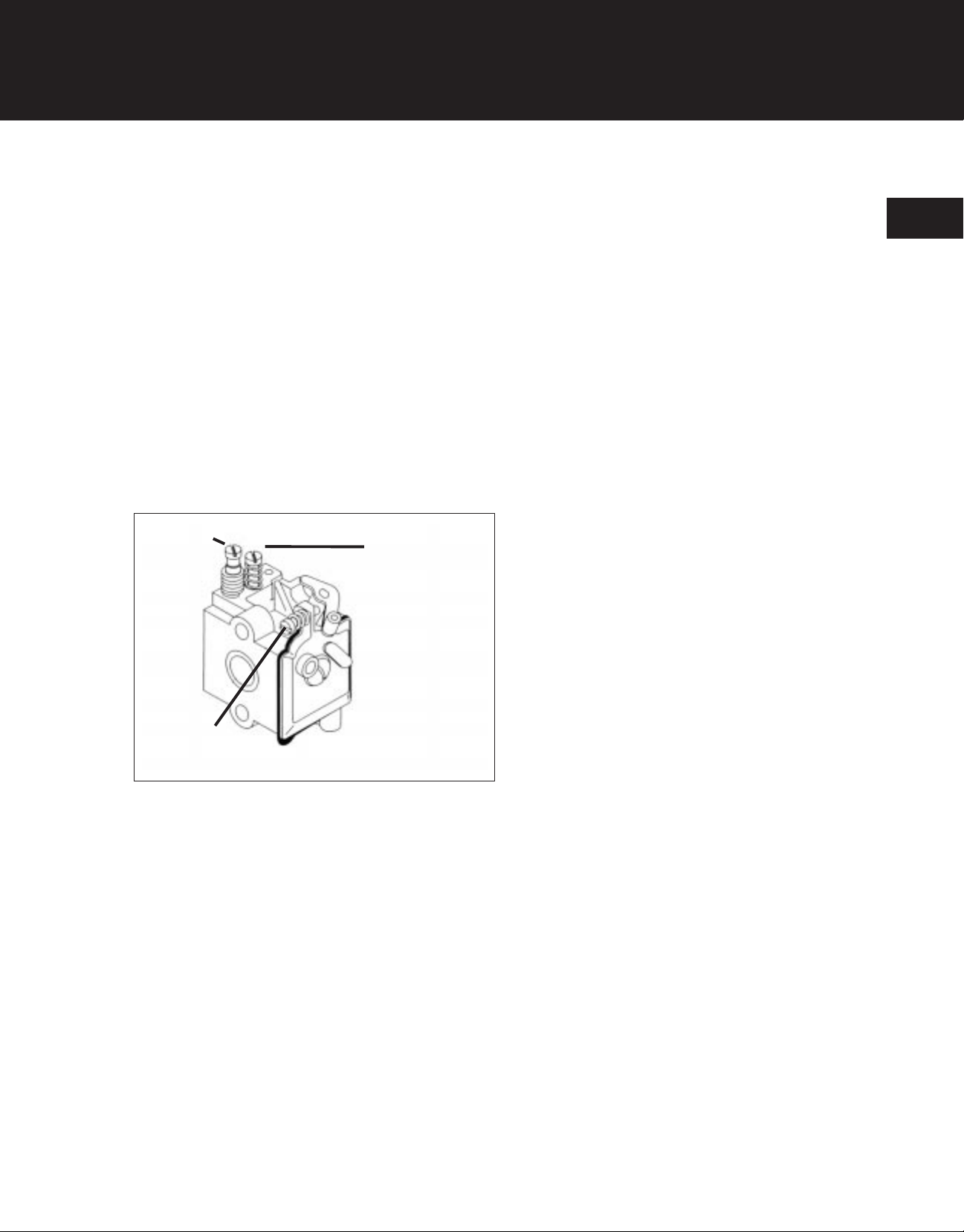
(H) High Speed
Mixture Needle
Final Carburetor Adjustment
Make final adjustments to the carburetor when the
unit is fully reassembled. Refer to “Carburetor Adjustment” in Part 1 — General Information.
Idle Speed
(L) Idle
Mixture Needle
3
Remove Carburetor Mount/Reed Plate And Fuel
Tank
Trimmers And Cultivators
1. Remove the four screws securing the
carburetor mount/reed plate to the
crankcase.
2. Remove the carburetor mount/reed plate and carburetor mount/reed plate gasket.
3. Remove the fuel tank (held in place by the
carburetor mount/reed plate).
Blowers And Blower/Vacs
3.6069.010
2.6081.045
The fuel tank on blowers and blower/vacs is held in
place by the engine side covers. Remove the engine
side covers to remove the fuel tank.
Remove the carburetor mount/reed plate as follows:
Models 280, 300BV, 310, And 310BV
1. Remove the four screws securing the carburetor
mount/reed plate to the crankcase .
2. Remove the carburetor mount/reed plate and carburetor mount/reed plate gasket.
3-22
2.6081.046
Page 48

DISASSEMBLY, INSPECTION, & REPAIR
DISASSEMBLE MAJOR
COMPONENTS (cont.)
Model 200/210
1. Remove the screw securing the carburetor
mount/reed plate to the crankcase.
2. Remove the carburetor mount/reed plate and
carburetor mount/reed plate gasket.
2.6081.047
2.6277.140
3
Fuel Tank And Lines Disassembly, Inspection,
And Reassembly
Fuel Tank And Cap
1. Inspect the fuel tank for cracks, rubbing, or
chaffed spots. Replace the tank if necessary.
2. Inspect the rubber fuel tank mounting pads
(on either side of the tank) for condition. Replace the mounts if necessary.
3. Inspect the fuel tank cap for cracks, damaged
vent valve, or other visible signs of damage.
Replace the cap if necessary.
Fuel Line And Filter Removal
Units equipped with a primer have two fuel lines to
the fuel tank. The clear line provides normal fuel
flow. The blue line provides a return line for excess
fuel flow during primer operation. The blue (primer)
line is removed/installed in the same manner as the
fuel line except it does not have a fuel filter.
2.6089.048
To remove the fuel lines and fuel filter:
1. Slide the retainer off of the fuel line/fitting.
2. Push the fuel fitting, fuel filter, and fuel line out
of the fuel tank through the tank neck.
3. If fuel the filter is dirty or clogged, replace it
with new fuel line assembly.
3-23
Page 49

DISASSEMBLY, INSPECTION, & REPAIR
DISASSEMBLE MAJOR
COMPONENTS (cont.)
Fuel Line And Filter Installation
1. Insert a piece of trimmer line through the hole in
the bottom of fuel tank to the filler opening. Slide
the fuel line over trimmer line.
2. Working through the filler neck, insert the fuel line
with the fuel filter and fitting attached through
the hole in the bottom of tank.
3
3. Work the fuel line from outside of tank, pulling
until the filter is seated against the bottom of the
tank
4. Slip the retainer over the fuel line and onto the fitting protruding out of the bottom of the tank.
Reed And Reed Backup Plate Removal And
Installation
Fitting
Filter
2.6089.049
Tank Wall
Fuel Line
Retainer
3.6089.050
Reed And Reed Backup Removal
Trimmers And Cultivators, And Models 280,
300BV, 310, And 310BV Blowers And Blower/Vacs
1. Remove the screw(s) securing the reed and reed
backup to the carburetor mount/reed plate.
2. Remove the reed and reed backup.
3-24
2.6089.051
Page 50

DISASSEMBLY, INSPECTION, & REPAIR
DISASSEMBLE MAJOR
COMPONENTS (cont.)
Model 200/210 Blowers
1. Remove the screw(s) securing the reed valve
components to the carburetor mount/reed
plate.
2. Remove the reed backup, reed, reed valve
seat, and valve seat gasket.
2.6089.052
Correct
Incorrect
3.6089.053
3
Reed And Reed Backup Installation
NOTE: Pay attention to the shape of the carbu-
retor mount/reed plate surface the reed and
reed backup are mounted on.
All blowers and blower/vacs, and older trimmers and
cultivators have a “flat” reed mounting surface. The
reed valve for these units have a slight downward
curve.
3.6090.137
Newer trimmers and cultivators have a reed mounting surface that is curved upward. The reed valve
for these units is flat.
If unit has flat reed plate, make sure a gap of 0.105-
0.110 (2.7-2.8 mm) is maintained between the carbu-
retor mount/reed plate and reed backup plate.
3-25
Page 51

DISASSEMBLY, INSPECTION, & REPAIR
DISASSEMBLE MAJOR
COMPONENTS (cont.)
Trimmers And Cultivators, And Models 280, 300BV,
310, And 310BV Blowers And Blower/Vacs
1. If applicable, make sure the curve of the reed
valve is down.
2. Install the reed, reed backup, and reed mounting
screw(s).
Torque the screw(s) to 15-20 in•lb (1.7-2.3 N•m).
3
2.6089.051
Model 200/210 Blower
1. Install the reed valve seat gasket and valve seat.
2. Make sure the curve of the reed valve is in the direction shown in
3. Install the reed, reed backup, and reed mounting
screw(s).
Torque the screw(s) to 15-20 in•lb (1.7-2.3 N•m)
Remove Muffler
1. Remove the muffler mounting bolts.
2.6089.052
2. Remove the muffler (with heat shield) and
gasket. Discard the old gasket.
3-26
2.6089.054
Page 52

DISASSEMBLY, INSPECTION, & REPAIR
DISASSEMBLE MAJOR
COMPONENTS (cont.)
Heat Shield Removal
1. For Models 280, 300BV, 310, And 310BV
Blowers And Blower/Vacs— Remove the 4
screws securing the lower plate of heat
shield to the main part of shield.
2.6089.055
2.6089.056
3
2. Remove the screw securing the heat shield to
the muffler
Exhaust Exit Tube Removal
The exhaust exit tube is removable on some mufflers. For all other mufflers, the exhaust tube is
welded in place and is not removable. To remove
the exhaust exit tube (when possible):
2.6089.057
1. Remove the screws securing the exhaust exit
tube to the muffler body.
2. Remove the exhaust exit tube and gasket.
3-27
Page 53

DISASSEMBLY, INSPECTION, & REPAIR
DISASSEMBLE MAJOR
COMPONENTS (cont.)
Inspection And Cleaning
The muffler should be removed periodically to inspect
for excessive carbon build-up. Excessive deposits
around the exhaust ports or exhaust exit holes will
cause poor engine performance.
1. Check the inlet port of muffler for excessive
carbon deposits. Clean as required.
3
2. Inspect the baffle inside muffler for carbon buildup. Clean baffle by scraping carbon as required.
Use a piece of wire to clear obstructions from
the small holes in baffle.
If carbon build-up can not be cleaned, replace the
muffler.
3. Inspect the muffler mounting holes for elongation.
Replace the muffler if the holes are elongated.
2.6089.058
Wire
3.6089.059
Muffler Reassembly
1. Install a new gasket and the exhaust exit tube
(for mufflers with removable exhaust tubes).
Secure the tube with 2 screws.
Torque the screws to 15-25 in•lb (1.7-2.8 N•m).
3-28
2.6089.057
Page 54

DISASSEMBLY, INSPECTION, & REPAIR
DISASSEMBLE MAJOR
3. For Models 280, 300BV, 310, And 310BV
Blowers And Blower/Vacs— Install the lower
COMPONENTS (cont.)
plate of heat shield to the main part of
shield. Secure the lower plate with 4 screw
2. Install the heat shield and mounting screw to
muffler body. Make sure the holes in the
heat shield align with mounting holes in muffler body.
Torque the screw 15-25 in•lb (1.7-2.8 N•m).
2.6089.056
2.6089.055
3
Remove Clutch
Some units are equipped with a clutch. If no clutch
exists proceed to “Remove Starter Housing.”
1. Remove the four screws securing the clutch
cover to starter housing. Remove the clutch
cover.
NOTE: Early models used Loctite® to secure
the screw in the clutch drum. It may be difficult
to remove these screws, use a hardened screwdriver, or screwdriver bit with a clean and sharp
blade.
Units with serial number 71200438 and greater
use a #T20 Torx® head screw to secure the
clutch drum.
2. Install flywheel holder, P/N 612470.
3. Using the appropriate screwdriver or screwdriver bit, loosen screw inside of the clutch
drum.
Remove the clutch drum.
2.6089.060
3-29
Page 55

DISASSEMBLY, INSPECTION, & REPAIR
DISASSEMBLE MAJOR
COMPONENTS (cont.)
4. Using clutch tool, P/N 147337, remove the clutch
rotor.
5. Remove the spacer sleeve from crankshaft.
Flywheel
Holder
3
Inspection
1. Check the clutch drum, rotor, and spring for wear
or damage. Replace if necessary.
2. Inspect the condition of the screw head inside of
clutch drum. If head is slotted or damaged,
replace the clutch drum.
2.6089.061
Flywheel Holder
Clutch Tool
2.6089.062
3-30
2.6089.120
Page 56

DISASSEMBLY, INSPECTION, & REPAIR
DISASSEMBLE MAJOR
COMPONENTS (cont.)
4. If the unit is equipped with an ignition switch or
push-to-stop switch in the starter housing,
Remove Starter Housing
disconnect the switch lead from the ignition
module.
Trimmers And Cultivators
1. If necessary, disconnect the spark plug wire
from spark plug and remove the spark plug.
2. Remove the screw securing the shroud
extension/engine stand to the starter housing. Remove the shroud extension/engine
stand.
2.6089.063
3
Cultivator Tank
Guard Bracket
2.6089.065
3. Remove the screws securing the starter
housing to the fan shroud. Remove the
starter housing.
For Cultivators— Also remove the fuel tank
guard bracket.
2.6089.064
3-31
Page 57

DISASSEMBLY, INSPECTION, & REPAIR
DISASSEMBLE MAJOR
COMPONENTS (cont.)
Blowers And Blower/Vacs—
Models 280, 300BV, 310, And 310BV
1. If necessary, disconnect the spark plug wire from
spark plug and remove the spark plug.
2. Install flywheel holder, P/N 612470.
3. Remove the crankshaft extension nut from crankshaft.
4. Remove the spacer sleeve from crankshaft.
3
5. Remove the screw securing the shroud extension
to the starter housing. Remove the shroud extension.
Flywheel Holder
2.6089.066
2.6089.067
6. Remove the screws securing the starter housing
to the fan shroud. Remove the starter housing.
3-32
2.6089.068
Page 58

DISASSEMBLY, INSPECTION, & REPAIR
DISASSEMBLE MAJOR
COMPONENTS (cont.)
Toggle Switch
Ignition Switch Replacement
Some models are equipped with an ignition switch
1. Disconnect the lead wires from switch.
installed in the starter housing or styling cover. Several types of switches have been used. Service the
switches as follows:
2. Remove the nut, switch plate and switch body.
3. Reassemble the switch in the reverse order of
disassembly.
Torque the nut to 25-35 in•lb (2.8-3.9 N•m).
3.6090.134
3.6089.069
3
Slide Switch
1. Remove the screw, lead wire, contact plate,
and switch cover.
2. Remove the screw and slide contact.
3. Reassemble the switch in the reverse order of
disassembly.
Torq ue the screw securing the slide contact to
starter housing to 10-15 in•lb (1.1-1.7 N•m).
Torque the screw securing the lead wire and
contact plate to switch cover to 7-12 in•lb (0.8-
1.4 N•m).
2.6089.070
3-33
Page 59

DISASSEMBLY, INSPECTION, & REPAIR
DISASSEMBLE MAJOR
COMPONENTS (cont.)
Push Button Switch
1. Remove the screw and washer securing the
switch into the styling cover.
2. Pull the switch out of the styling cover from the
back. The push button cap will come off of the
switch as it is removed.
3. Reassemble the switch in the reverse order of
disassembly.
3
3.6089.071
Starter Disassembly, Repair, And Reassembly
WARNING: Spring under tension!
The rope starter on these engines contains a flat wire
spring that is under tension. eye and hand
protection when replacing worn or broken spring, in
case it should uncoil as it is handled. Allow spring
tension to be completely relieved and make sure
pulley disengages from spring before removing the
pulley retainer(s), pulley, and starter spring from
housing.
Adding Starter Spring Tension
If the rope pull handle does not fully return against
the starter housing, the spring may need another turn
of tension. Additional tension can be added without
disassembling the starter.
To add spring tension:
2.6060.153
1. Pull the rope out a short distance and hold the
pulley from turning.
2. Wind one or more extra turns of rope onto the
pulley.
3-34
2.6089.072
Page 60

DISASSEMBLY, INSPECTION, & REPAIR
DISASSEMBLE MAJOR
COMPONENTS (cont.)
NOTE: If necessary, loosen the pulley re-
tainer(s) screw(s) while holding the pulley down
to provide clearance between the retainer(s)
and pulley. Torque the retainer(s) screw(s) to 2030 in•lb (2.3-3.4 N•m) after additional rope is
wound onto pulley.
2.6089.082
2.6090.135
3. Pull the rope out to its full length and let it
return until the pull handle rests against the
starter housing.
NOTE: Do not add any more tension than is
necessary to make the pull handle return
against the starter housing. Adding excessive
spring tension can cause the spring to break.
If spring pressure is weak, and adjustment will
not enable the pull handle to return against the
starter housing
,
replace the spring.
3
2.6089.073
Starter Disassembly
1. Relieve the spring tension by removing the
pull handle and allowing the pulley to slowly
unwind inside the starter housing. Make
sure the spring tension is fully relieved
before proceeding.
2. Remove screw(s) and pulley retainer(s)
3-35
Page 61

DISASSEMBLY, INSPECTION, & REPAIR
DISASSEMBLE MAJOR
COMPONENTS (cont.)
3. Remove the starter pulley from the starter
housing.
3
4. If necessary, carefully remove the starter spring
from the starter housing using a needle-nose
pliers.
NOTE: Once the starter spring is removed from the
starter housing, a service replacement spring (prewound and contained in a spring retainer) should be
used to reassemble the starter. Reinstallation of the
old starter spring is not recommended.
5. Remove the starter rope from the pulley.
2.6089.074
2.6089.075
6. Remove the rope guide bushing from the starter
housing.
NOTE: Some models use 2 rope guide bushings.
One in the starter housing, and one between the
starter housing and the pull handle.
3-36
2.6089.076
Page 62

DISASSEMBLY, INSPECTION, & REPAIR
DISASSEMBLE MAJOR
COMPONENTS (cont.)
Inspection And Service
1. Inspect the starter rope for wear or frays. Replace the rope if necessary.
2. Inspect the starter pulley for worn pawl engagement teeth. Also check for wear on the
surface of pulley that is in contact with the
starter spring.
3. Make sure old grease and dirt are cleaned
from all starter components before reassembling.
2.6047.092
2.6089.077
3
Starter Reassembly
1. Install the starter spring into the starter
housing as follows:
a. Orient the replacement starter spring so the
spring windings are clockwise (the open end
of spring hook is to the left).
2.6089.078
b. Grasp the spring near the spring hook with a
needle-nose pliers and carefully remove the
spring retainer.
3-37
Page 63

DISASSEMBLY, INSPECTION, & REPAIR
DISASSEMBLE MAJOR
COMPONENTS (cont.)
c. Place the spring into the starter housing.
Make sure the spring hook is installed over
the post in the starter housing.
d. Make sure the spring windings are laying flat
against the starter housing around the entire
circumference of the spring. Hold the spring
in this position and carefully release the
needle-nose pliers holding the spring.
Post
3
2. Insert the rope through the hole in starter pulley.
Tie a single knot in the rope approximately 0.5
in. (12.7 mm) from the end.
3. Pull the rope tight, pulling the knot into the pocket
in the pulley. Using a screwdriver or similar tool,
push the end of the rope into the slot in the
pulley.
4. Hold the pulley with the pawl engagement teeth
towards you. Wrap the rope around the pulley in
the clockwise direction. Make sure all of the
rope is wound onto the pulley.
2.6089.079
2.6089.080
5. Apply a small amount of grease (Mobilgrease®
HP or equivalent) to the post in starter housing,
the spring, and the backside of pulley.
6. Install the rope guide bushing into the starter
housing.
3-38
2.6089.076
Page 64

DISASSEMBLY, INSPECTION, & REPAIR
DISASSEMBLE MAJOR
9. Install the pulley retainer(s) and screw(s).
COMPONENTS (cont.)
Torque the screws to 20-30 in•lb (2.3-3.4
N•m).
7. Install the pulley/rope assembly into the starter
housing. Rotate the pulley slightly until the
10. Pull the rope out to its full length and let it respring hooks onto the pulley and the pulley
turn. Check the spring tension and adjust as
drops into place.
necessary. Refer to “Adding Starter Spring
Tension” above.
2.6089.074
2.6089.081
Remove Ignition Module
1. Make sure the spark plug wire, and the lead
wires to the ignition module are disconnected.
8. Route rope through the guide bushing in the
starter housing. If so equipped, install the
additional rope guide bushing over the rope.
2. Remove the screws securing the ignition
module to the cylinder. Remove the ignition
module and, if so equipped, the push-to-
Install the pull handle on the rope and secure it
stop switch wire.
with a single knot.
Remove Flywheel
WARNING: Cracked or Broken Cooling Fins
Are A Hazard!
3
2.6089.082
Be careful not to crack or break any cooling fins.
They could fly off during operation. If cooling fins are
cracked or broken, replace the flywheel.
3-39
Page 65

DISASSEMBLY, INSPECTION, & REPAIR
DISASSEMBLE ENGINE
1. For Non-clutch Units and the Model 200/210
Blower— Hold the flywheel with a strap wrench
or spanner wrench and remove the flywheel as
follows:
a. For Non-clutch units— Remove the square
drive nut.
b. For the Model 200/210 Blower— Remove the
flywheel retaining nut and split lock washer.
2. Using a plastic-faced mallet, gently tap on the fly-
3
wheel until it breaks free from the crankshaft.
3. Remove the flywheel from the crankshaft.
4. Remove the flywheel key from crankshaft.
Flywheel Inspection And Repair
Inspect the flywheel for the following conditions:
• Missing, broken, or cracked fins.
Oval shaped pawl pin holes.
• Broken, damaged or missing springs, pawls, or pawl pins. Freedom of movement of pawls.
• Evidence that the Starter Pawl Repair Kit has been
installed (holes in bottom of the flywheel below pawl
pins).
2.6089.083
2.6089.084
• Other signs of fatigue, wear, or damage to the
flywheel.
Starter Pawl Repair Kit, P/N 180142, is available to repair the flywheel. This kit contains 2 pawl pins (oversized*), 2 pawl springs, and 2 pawls. To install the kit, an
arbor press, 0.228 in (5.79 mm) drill, and drill press are
required. Installation instructions are provided in the kit.
3-40
2.6089.085
Page 66

DISASSEMBLY, INSPECTION, & REPAIR
DISASSEMBLE ENGINE (cont.)
*NOTE: The pawl pins in this kit are oversized.
Once this kit is installed, the flywheel cannot be repaired a second time.
For all other damage, replace the flywheel.
CONTENTS OF KIT
#180142
2.6089.086
2.6060.161
3
2 Starter Pawl Pins
(oversized)
2 Starter Pawl Springs
2 Starter Pawls
3.6078.093
3-41
Page 67

DISASSEMBLY, INSPECTION, & REPAIR
DISASSEMBLE ENGINE (cont.)
Remove Fan Shroud
1. Remove the screws securing the fan shroud to
crankcase.
2. Remove the fan shroud.
3
Remove Spark Plug, Cylinder, And
Piston/connecting Rod Assembly
1. Remove the spark plug from cylinder.
Service the spark plug as instructed in
Part 1 — General Information.
2.6089.087
2.6089.088
2. For Model 200/210 Blower— Remove the
crankcase cover screws, crankcase cover, and
gasket.
3-42
2.6089.089
Page 68

DISASSEMBLY, INSPECTION, & REPAIR
DISASSEMBLE ENGINE (cont.)
3. Remove the cylinder mounting screws.
2.6089.090
2.6089.091
3
4. Remove the connecting rod from crankshaft.
5. Remove the cylinder with piston/connecting
rod assembly from the crankcase as a unit.
Remove the cylinder gasket.
2.6089.092
6. Remove the piston/connecting rod assembly
from the cylinder.
3-43
Page 69

DISASSEMBLY, INSPECTION, & REPAIR
DISASSEMBLE ENGINE (cont.)
7. Remove the piston ring from the piston
NOTE: Do not disassemble the
piston/connecting rod further.
Cylinder And Piston Inspection
1. Inspect the cylinder, piston, and piston ring for
wear and damage. Refer to the specifications
and tolerances in Part 1 — General Information.
Replace the cylinder, piston, or piston ring if
necessary.
3
2. Install the piston ring into the ring groove in
piston and check the side clearance of piston
ring. The maximum side clearance is 0.005 inch
(0.127 mm). Replace the ring and piston if necessary.
NOTE: Units with serial numbers below
910045201 use a piston ring having a width of
0.046 inch (1.16 mm) minimum. Units with serial
numbers 910045201 and greater use a piston
ring having a width of 0.052 inch (1.23 mm) minimum.
3. Inspect the ring groove on piston for carbon
deposits. Clean the ring groove thoroughly.
Remove Crankshaft, And Crankcase
Disassembly, Inspection, And Reassembly
2.6089.093
2.6089.094
Arbor Press
NOTE: Crankcase disassembly and reassembly
requires the use of an arbor press and suitable
drift punches and bearing supports. If these are
not available, do not attempt to repair the crank-
case assembly. Refer to the appropriate parts
manual to order a complete crankcase/crankshaft
assembly.
Crankcase Disassembly
1. Using arbor press, press the crankshaft and
thrust washer out of crankcase.
3-44
2.6089.095
Page 70

Bearing
Puller
DISASSEMBLY, INSPECTION, & REPAIR
DISASSEMBLE ENGINE (cont.)
2. Remove the outer (sealed) bearing from the
flywheel side of the crankcase using a bearing puller.
2.6089.096
2.6089.097
3
3. Remove the inner (unsealed) bearing from the
inside of the crankcase.
2.6089.098
4. If so equipped, remove the snap rings securing the inner seal in crankcase. Discard the
snap rings.
NOTE: Units with serial number 203125000
and greater do not use snap rings in the crankcase.
3-45
Page 71

DISASSEMBLY, INSPECTION, & REPAIR
DISASSEMBLE ENGINE (cont.)
5. Remove the inner seal from crankcase.
3
Inspection
1. Inspect the crankcase for nicks, cracks, and deformation. Replace if necessary.
2. Inspect the crankshaft for nicks, cracks,
roundness and deformation. Replace if
necessary.
Crankcase Reassembly
2.6089.099
2.6090.133
NOTE: To prevent bearing damage, make sure
bearings are fully supported on both the inner and
outer races during all pressing operations.
Make sure the inner surface of crankcase and mating surfaces of bearings and seal are clean, dry, and
free from grease and oil.
3-46
3.6090.129
Page 72

DISASSEMBLY, INSPECTION, & REPAIR
DISASSEMBLE ENGINE (cont.)
1. Make sure the race of the outer (sealed) bearing is packed with grease. If necessary, apply a small amount of a high quality grade 2
lithium-based (or equivalent) bearing grease
to the bearing. Keep the grease off of the inner and outer bearing surfaces that mate
against the crankcase and crankshaft.
2. Press the outer (sealed)bearing into the crankcase until it is flush with the crankcase sur-
2.6089.100
face. Make sure the rubber seal is to the outside.
3
Bearing
Support
3. Press the inner seal into the crankcase to a
depth of 0.400 in. (10.2 mm) as shown in
Figure 3-88. Make sure the lips of the inner
seal face away from the outer bearing.
Lightly lubricate the lips of the inner seal with
2-Cycle engine oil.
3.6089.102
4. Install the thrust washer onto the crankshaft.
5. Press the inner (unsealed) bearing onto the
crankshaft until it makes light contact with
the thrust washer.
2.6089.101
3-47
Page 73

DISASSEMBLY, INSPECTION, & REPAIR
DISASSEMBLE ENGINE (cont.)
6. Press the crankshaft/bearing assembly into the
crankcase until the bearing is flush with the inner surface of the crankcase.
Bearing
Support
3
7. Check the clearance between the inner
surface of the crankcase and the crankshaft
counterweight at several points
Recommended clearance is 0.030 in. (0.762 mm).
Adjust the location of the crankshaft/bearing if
necessary.
2.6089.104
2.6089.105
3-48
Page 74

REASSEMBLY
General Information ..........................
Troubleshooting ............................
Disassembly, Inspection and Repair ..................
Reassembly ..............................
1
2
3
4
4-1
Page 75

REASSEMBLY
Typical Assembly Sequence ............ 4-4
Engine Reassembly .................. 4-5
Install Piston/Connecting Rod
And Cylinder To Crankcase,
Install Spark Plug .................. 4-5
Install Major Components ............... 4-9
Install Fan Shroud .................4-9
Install Flywheel ...................4-9
Install Ignition Module ............... 4-11
Table Of Contents
4
Install Starter Housing ............... 4-12
Trimmers And Cultivators ............ 4-12
Blowers And Blower/Vacs—
Models 280, 300BV, 310, And 310BV ......4-13
Install Clutch .................... 4-14
Install Muffler .................... 4-16
Install Fuel Tank And Carburetor
Mount/Reed Plate ................. 4-17
Trimmers And Cultivators ............ 4-17
Blowers And Bower/Vacs ............ 4-17
Install Carburetor, Choke, And Connect Fuel Lines 4-18
Round Air Filter—Trimmers
And Cultivators ................. 4-19
4-2
Square Air Filter—Trimmers
And Cultivators ................. 4-20
Square Air Filter—Blowers
And Blower/Vacs ................ 4-21
Page 76

REASSEMBLY
Install Air Filter ................... 4-22
Trimmers and Cultivators ............ 4-22
Blowers And Blower/Vacs ............4-23
Install Styling Cover ................ 4-23
Install Engine ....................4-24
Trimmers .................... 4-24
Cultivators .................... 4-26
Blowers And Blower/Vacs ............4-26
Prepare The Unit For Operation .......... 4-26
4
4-3
Page 77

REASSEMBLY
Typical Assembly Sequence
The following sequence is suggested for complete
engine reassembly. This procedure assumes that all
components are new or have been reconditioned, and
all component subassembly work has been
completed. This procedure can be varied to
accommodate individual requirements for assembly
and repair.
NOTE: Make sure the engine is assembled using all
specified torque values and clearances. Failure to
observe specifications can cause severe engine wear
or damage.
Always use new gaskets.
1. Install Piston/Connecting Rod And Cylinder
To Crankcase, Install Spark Plug
2. Install Fan Shroud
4
3. Install Flywheel
4. Install Ignition Module
5. Install Starter Housing
6. Install Clutch
7. Install Muffler
8. Install Fuel Tank And Carburetor
Mount/Reed Plate
9. Install Carburetor And Choke,
Connect Fuel Lines
10. Install Air Filter
11. Install Styling Cover
12. Install Engine Into Equipment
13. Prepare The Unit For Operation
* On some units, these can be removed and reinstalled
without removing the engine from its normal operating
installation.
4-4
Page 78

2.6089.093
REASSEMBLY
ENGINE REASSEMBLY
Install Piston/Connecting Rod And Cylinder To
Crankcase, Install Spark Plug
1. If necessary, install the piston ring onto the
piston. Make sure the ring end gap is
located over the anti-rotation pin in the
piston ring groove.
Exhaust Port
Piston Ring
Anti-rotation
Pin
4
2. Lubricate the piston and piston ring with
2-Cycle engine oil. Compress the piston ring
and insert the piston into the cylinder.
2.6089.106
For Trimmers, Cultivators, and Models 280,
300BV, 310, And 310BV Blowers and
Blower/Vacs— Position the piston ring antirotation pin/end gap so it faces away from the exhaust port of cylinder.
2.6089.107
4-5
Page 79

REASSEMBLY
ENGINE REASSEMBLY (cont.)
For Model 200/210 Blower— Position the longer skirt
of piston so it is on the same side as the
exhaust port of cylinder.
Long Skirt
Exhaust Port
2.6089.108
4
3. Position a new cylinder gasket on cylinder as
follows:
For Trimmers And Cultivators— Position the
longer, straight edge of gasket so it is on the
same side as the exhaust port of cylinder.
For Models 280, 300BV, 310, And 310BV
Blowers and Blower/Vacs— Position the longer,
straight edge of gasket so it faces away from the
exhaust port of cylinder.
2.6089.109
4-6
2.6089.110
Page 80

Exhaust Port
REASSEMBLY
ENGINE REASSEMBY (cont.)
For Model 200/210 Blower— With the exhaust
port of cylinder to the left, position the edge of gasket with the small notch to the left (nearest exhaust port)
2.6089.111
4
4. Position the cylinder to the crankcase as
follows:
Carb. Mount/
Reed Plate
Mounting Hole
For Trimmers, Cultivators, and Models 280,
300BV, 310, And 310BV Blowers and
Blower/Vacs— Position the exhaust port of
cylinder so it is on the same side as the open side
of crankcase.
2.6089.112
For Model 200/210 Blower— Position the
exhaust port of the cylinder so it is on the side opposite the hole in crankcase for the carburetor
mount/reed plate.
Exhaust Port
2.6089.113
4-7
Page 81

REASSEMBLY
ENGINE REASSEMBLY (cont.)
5. Lubricate the pin on crankshaft counterweight
with 2-Cycle engine oil. Slip the connecting rod
bearing over the pin.
2.6089.114
4
6. Secure the crankcase to the cylinder with two
hex socket head screws.
Torque the screws to 110-120 in•lb
(12.4-13.5 N•m).
7. For Model 200/210 Blower— Install a new
crankcase cover gasket, the crankcase cover
(with flat inner surface towards cylinder), and
attaching screws.
Torque the screws to 67 in•lb (7.5 N•m).
2.6089.090
4-8
2.6089.089
Page 82

2.6089.088
REASSEMBLY
ENGINE REASSEMBLY (cont.)
8. Make sure the spark plug gap is set to 0.025
inch (0.635 mm) using a wire feeler gauge.
Install the spark plug into cylinder and torque to
190-210 in•lb (21.4-23.6 N•m).
INSTALL MAJOR COMPONENTS
2.6089.087
4
Install Fan Shroud
1. Install the fan shroud to crankcase with 4
screws.
2. Torque the screws to 110-120 in•lb (12.4-13.5
N•m).
Install Flywheel
WARNING: Cracked or Broken Cooling
Fins Are A Hazard!
Be careful not to crack or break any cooling fins. They
could fly off during operation. If cooling fins are
cracked or broken, replace the flywheel.
2.6089.086
1. Install the crankshaft key into the keyway on
crankshaft.
4-9
Page 83

REASSEMBLY
INSTALL MAJOR COMPONENTS
(cont.)
2. Position the flywheel so that the key slot in the
flywheel aligns with the crankshaft key. Place the
flywheel onto the crankshaft.
2.6089.115
4
3. For Clutch Units, and Models 280, 300BV, 310, And
310BV Blowers and Blower/Vacs—
Proceed to “Install Ignition Module”.
For Non-clutch Units And The Model 200/210
Blower— Secure the flywheel to the crankshaft
as follows:
a. For Non-clutch Units— Install the square
drive nut
For the Model 200/210 Blower— Install the split
lock washer and flywheel retaining nut.
2.6089.084
4-10
2.6089.085
Page 84

2.6089.116
REASSEMBLY
INSTALL MAJOR COMPONENTS
(cont.)
b. Hold the flywheel with a spanner wrench or
strap wrench and torque the nut to 150-160
in•lb (16.9-18 N•m).
Optional
Stop Switch
2.6089.083
Flat Feeler
Gauge
4
Install Ignition Module
1. Install the ignition module, the stop switch wire
or ground lead tab terminal (if so equipped),
and module fastening screws
2. Move the ignition module away from the
flywheel as far as possible. Tighten the
fastening screws slightly.
3. Insert a 0.010-0.015 in. (0.254-0.381 mm) feeler
gauge or shim stock between the
ignition module and flywheel magnet
surfaces.
2.6089.117
NOTE: Brass or plastic feeler gage or shim stock
is more suitable for this application because of the
magnetic forces.
4. Loosen the module fastening screws and push
the ignition module tight against the feeler
gauge or shim stock.
4-11
Page 85

REASSEMBLY
INSTALL MAJOR COMPONENTS
(cont.)
Torque the screws to 28-35 in•lb (3.2-3.9 N•m).
Remove the feeler gauge or shim stock.
5. Connect ignition switch lead wires as
necessary.
2.6089.083
Install Starter Housing
4
Trimmers And Cultivators
1. If the unit is equipped with an ignition switch or pushto-stop switch, connect the switch lead to the ignition module.
2. Install the the starter housing to the fan shroud and
secure with four screws.
For Cultivators— Also install the fuel tank guard
bracket.
Torque the screws to 35-40 in•lb (3.9-4.5 N•m).
2.6089.064
NOTE: It may be necessary to pull the starter
rope slightly to enable the starter housing to drop
into position.
4-12
2.6089.065
Page 86

2.6089.063
REASSEMBLY
INSTALL MAJOR COMPONENTS
(cont.)
3. Install the shroud extension/engine stand
around the cylinder. Make sure the tabs in the
shroud extension/engine stand are
inserted in the slots in the fan shroud. Make
sure the spark plug wire and ignition switch
leads are properly routed out of the starter
housing.
4. Install the fastening screw through the starter
housing and into the shroud extension/
engine stand.
Torque the screw to 25-35 in•lb (2.8-3.9 N•m).
Blowers And Blower/Vacs—Models 280, 300BV,
310, And 310BV
1. Connect the push-to-stop switch leads to the
ignition module.
4
2.6089.068
2. Install the starter housing to the fan shroud and
secure with four screws.
Torque the screws to 35-40 in•lb (3.9-4.5 N•m).
NOTE: It may be necessary to pull the starter
rope slightly to enable the starter housing to drop
into position.
3. Install the shroud extension around the
cylinder. Make sure the tabs in the shroud extension are inserted in the slots in the fan
shroud. Make sure the spark plug wire and
stop switch leads are properly routed out of
the starter housing.
2.6089.067
4-13
Page 87

REASSEMBLY
INSTALL MAJOR COMPONENTS
(cont.)
4. Install the fastening screw through the starter housing and into the shroud extension.
Torque the screw to 25-35 in•lb (2.8-3.9 N•m).
5. Install the spacer sleeve over the crankshaft and install crankshaft extension nut.
Crankshaft
Extension Nut
Spacer Sleeve
2.6089.118
4
6. Install the flywheel holder, P/N 612470.
Torque the crankshaft extension nut to
150-160 in•lb (16.9-18 N•m).
Install Clutch
Some units are equipped with a clutch. If no clutch exists proceed to “Install Muffler.”
1. Install the spacer sleeve over the crankshaft.
Flywheel
Holder
2.6089.119
2. Install the clutch rotor to the crankshaft. Make
sure the side marked “OUT” is facing away from
the starter housing.
4-14
2.6089.120
Page 88

Clutch Tool
REASSEMBLY
INSTALL MAJOR COMPONENTS
(cont.)
3. Install the flywheel holder, P/N 612470.
Using clutch tool, P/N 147337, torque the clutch ro-
tor to 150-160 in•lb (16.9-18 N•m).
2.6089.121
Flywheel
Holder
4
4. Apply a small amount of Loctite® #271 to the
female threads of crankshaft.
5. Install the clutch drum to the crankshaft.
Torque the screw inside clutch drum to 38-44 in•lb
(4.3-5.0 N•m).
6. Remove the flywheel holder.
2.6089.122
7. Position the raised boss inside the “snout” of the
clutch cover towards the rope pull handle. Install the clutch cover to the starter housing
and secure with four screws.
Torque the screws to 35-40 in•lb (3.9-4.5 N•m).
2.6089.060
4-15
Page 89

REASSEMBLY
INSTALL MAJOR COMPONENTS
(cont.)
Install Muffler
1. Install a new muffler gasket, muffler, and
muffler mounting screws.
2.6089.054
4
For Trimmers And Cultivators— Make sure the
extended edge of the cylinder gasket is between
the muffler body and muffler heat shield.
For Model 200/210 Blower— Make sure the
shorter, straight edge of muffler gasket is to the
top (towards spark plug hole) of cylinder and the
angled corner is towards the ignition module.
2 . For Units With Serial Number Prior to 809000000—
Torque screws to 56 in•lb (6.3 N•m).
For Units With Serial Number 809000000 and
Greater— Torque screws to 80-90 in•lb
(9.0-10.1 N•m).
3.6089.123
4-16
2.6089.124
Page 90

2.6089.125
REASSEMBLY
INSTALL MAJOR COMPONENTS
(cont.)
Install Fuel Tank And Carburetor Mount/Reed Plate
Trimmers And Cultivators
1. Install the rubber fuel tank mounting pads to the
fan shroud and carburetor mount/reed plate.
2. Position the fuel tank against the fan shroud.
Install a new carburetor mount/reed plate
gasket, the carburetor mount/reed plate, and
attaching screws.
4
Ground Tab
Torque the screws to 60-65 in•lb (6.8-7.3 N•m).
2.6081.045
Blowers And Bower/Vacs
The fuel tank on blowers and blower/vacs is held in
place by the engine side covers. Install the fuel tank
when installing the side covers.
Install the carburetor mount/reed plate as follows:
Models 280, 300BV, 310, And 310BV
1. Install a new carburetor mount/reed plate
gasket, carburetor mount/reed plate,
carburetor grounding lead tab terminal, and attaching screws
2. Torque the screws to 60-65 in•lb (6.8-7.3 N•m).
2.6081.046
4-17
Page 91

REASSEMBLY
INSTALL MAJOR COMPONENTS
(cont.)
Model 200/210 Blower
1. Install a new carburetor mount/reed plate
gasket, carburetor mount/reed plate
assembly, and attachingscrew.
2. Torque the screw to 60-65 in•lb (6.8-7.3 N•m).
2.6081.047
4
Install Carburetor, Choke, And Connect Fuel Lines
Two basic air filter and choke styles are used on trimmer and cultivator engines: A “round” air filter with a
choke “knob”, or a “square” air filter with choke “lever”.
A “square” air filter cover is also used on blowers and
blower/vacs.
Use the following procedures to install carburetor, fuel
lines, and choke:
NOTE: Units equipped with a primer will have two
fuel lines to the fuel tank. The clear line provides normal fuel flow. The blue line provides a return line for
excess fuel flow during the primer operation. The
primer return line is connected to the longer fitting of
the primer bulb.
2.6090.038
4-18
Return Line
3.6078.110
Page 92

2.6090.037
REASSEMBLY
INSTALL MAJOR COMPONENTS
(cont.)
1. Install a new carburetor gasket over the pins on
carburetor mount/reed plate.
2.6081.026
2. Install the carburetor and carburetor mounting
screws (Figure 4-40).
Torque the screws to 35-40 in•lb (3.9-4.5 N•m).
3. Connect the fuel line(s) to the carburetor and
primer bulb (if so equipped).
4
3.6089.128
4-19
Page 93

REASSEMBLY
INSTALL MAJOR COMPONENTS
(cont.)
Square Air Filter—Trimmers And Cultivators
1. Install a new carburetor gasket over the pins on carburetor mount/reed plate.
2.6090.037
2. Install the carburetor, choke plate, choke lever, wavy
4
washer, and carburetor mounting screws
Torque the screws to 35-40 in•lb (3.9-4.5 N•m).
3. Connect the fuel lines to the carburetor and
primer bulb.
2.6081.027
Short Fitting
(To Carburetor)
4-20
Long Fitting
(From Tank)
3.6089.128
Page 94

2.6090.037
REASSEMBLY
INSTALL MAJOR COMPONENTS
(cont.)
Square Air Filter—Blowers And Blower/Vacs
1. For Models 280, 300BV, 310, And 310BV— Install a new carburetor gasket over the pins on
carburetor mount/reed plate.
Bushings
4
2. Make sure the bushings are installed in the air filter base mounting holes.
NOTE: Models 280, 300BV, 310, And 310BV
blowers and blower/vacs, serial number
206058151 and greater, use a machined, stepped
bushing in the mounting hole under the choke
lever.
2.6089.129
2.6081.029
3. Install a new carburetor gasket, the carburetor,
air filter base, choke lever, wavy washer, and
carburetor mounting screws to the carburetor
mount reed plate.
Torque the screws to 35-40 in•lb (3.9-4.5 N•m).
4-21
Page 95

REASSEMBLY
INSTALL MAJOR COMPONENTS
(cont.)
4. For Models 280, 300BV, 310, And 310BV—
Connect the ground lead from the carburetor to
the tab terminal.
5. Connect the fuel lines to the fuel tank when
reinstalling the engine in the unit.
4
Install Air Filter
Make sure the air filter element is cleaned and oiled as
instructed in Part 1 — General Information. Install the
air filter element into the air filter cover.
Install the air filter cover as follows:
2.6081.028
3.6078.009
Trimmers and Cultivators
1. For Units With Square Air Filters—Place the choke
lever in the full CHOKE position.
4-22
2.6081.022
Page 96

2.6081.020
REASSEMBLY
INSTALL MAJOR COMPONENTS
(cont.)
2. Install the air filter cover and attaching screws.
Torque the screws to 15-25 in•lb (1.7-2.8 N•m).
2.6081.024
4
Blowers And Blower/Vacs
1. Squeeze the air filter cover with your fingers and
snap it into the air filter base.
Install Styling Cover
Some units are equipped with an engine styling cover.
To install the styling cover:
2.6081.018
1. If the unit is equipped with an ignition switch in
the styling cover, connect the switch leads.
2. Install the styling cover and secure it to the fan
shroud with two screws.
4-23
Page 97

REASSEMBLY
INSTALL MAJOR COMPONENTS
(cont.)
3. If so equipped, install the screw that attaches the
styling cover to the shroud extension/engine stand.
2.6081.019
Install Engine
4
Install the engine to the equipment as follows:
Trimmers
1. Slip the upper flex drive housing (boom) clamp
assembly onto the clutch cover/starter housing.
2. If the trimmer is a clutch unit capable of taking
attachments, install the compression spring onto
the clutch drum.
2.6089.131
4-24
2.6089.132
Page 98

2.6090.136
REASSEMBLY
INSTALL MAJOR COMPONENTS
(cont.)
3. Install the engine onto the trimmer flex drive
housing. Make sure the flex drive shaft mates
with the square drive of engine. Make sure the
slot in the flex drive housing aligns with the
boss in the clutch cover/starter housing.
Drive Housing
Clamp
Anti-Rotation
Screw
3.6081.016
4
4. Install the anti-rotation screw through clamp and
into boom.
Torque the anti-rotation screw to 15-20 in•lb
(1.7-2.3 N•m).
5. Torquethe nut and bolt of clamp assembly to 7080 in•lb (7.9-9.0 N•m).
6. Install the throttle control cable and insert it
through the hole in the swivel on carburetor
throttle lever.
Make sure the outer cover of throttle cable seats
in back of the carburetor mount/reed plate.
7. Adjust the throttle control cable in the swivel for
the full range of throttle travel.
2.6081.015
Torque the screw in the swivel to 9-12 in•lb
(1.0-1.4 N•m).
4-25
Page 99

REASSEMBLY
INSTALL MAJOR COMPONENTS
(cont.)
Cultivators
1. Install the engine to the cultivator using steps 2-7 of
the procedure for trimmers above.
2. Secure the cultivator handlebars to the handlebar
brackets on engine.
Blowers And Blower/Vacs
Refer to the Blowers and Blower/Vacs Service
Manual for complete engine installation procedures.
2.6081.017
4
Prepare The Unit For Operation
Before placing the unit back into service, be sure to do
the following:
• Make sure all fasteners are tightened securely.
• Fill the fuel tank with a fresh gasoline and 2-Cycle
oil mix. Refer to the “Fuel Recommendations” in
Part 1 — General Information.
• Adjust the carburetor high speed mixture, idle
mixture, and idle speed settings. Refer to
“Carburetor Adjustment” in Part 1 — General
Information.
• Reinstall the air filter cover.
2.6277.141
4-26
3.6069.010
 Loading...