

Toro 38607, 622R Power Throw, 622E Power Throw Operator's Manual
622Rand622EPowerThrow
ModelNo.38606—SerialNo.270000001andUp
ModelNo.38607—SerialNo.270000001andUp
FormNo.3355-529RevG
®
Snowthrowers
Operator'sManual
Introduction
Readthisinformationcarefullytolearnhowtooperate
andmaintainyourproductproperlyandtoavoidinjury
andproductdamage.Youareresponsibleforoperating
theproductproperlyandsafely.
YoumaycontactTorodirectlyatwww.Toro.comfor
productandaccessoryinformation,helpndinga
dealer,ortoregisteryourproduct.
Wheneveryouneedservice,genuineToroparts,or
additionalinformation,contactanAuthorizedService
DealerorToroCustomerServiceandhavethemodel
andserialnumbersofyourproductready.Figure1
identiesthelocationofthemodelandserialnumbers
ontheproduct.Writethenumbersinthespace
provided.
injuryordeathifyoudonotfollowtherecommended
precautions.
Figure2
1.Safetyalertsymbol
Thismanualuses2wordstohighlightinformation.
Importantcallsattentiontospecialmechanical
informationandNoteemphasizesgeneralinformation
worthyofspecialattention.
ReplacementEngineOwner’sManualsmaybe
orderedthroughtheenginemanufacturer.
Figure1
1.Modelandserialnumberlocation
ModelNo.
SerialNo.
Thismanualidentiespotentialhazardsandhas
safetymessagesidentiedbythesafetyalertsymbol
(Figure2),whichsignalsahazardthatmaycauseserious
©2008—TheT oro®Company
8111LyndaleAvenueSouth
Bloomington,MN55420
Registeratwww.Toro.com.
OriginalInstructions(EN)
PrintedintheUSA
AllRightsReserved
Safety
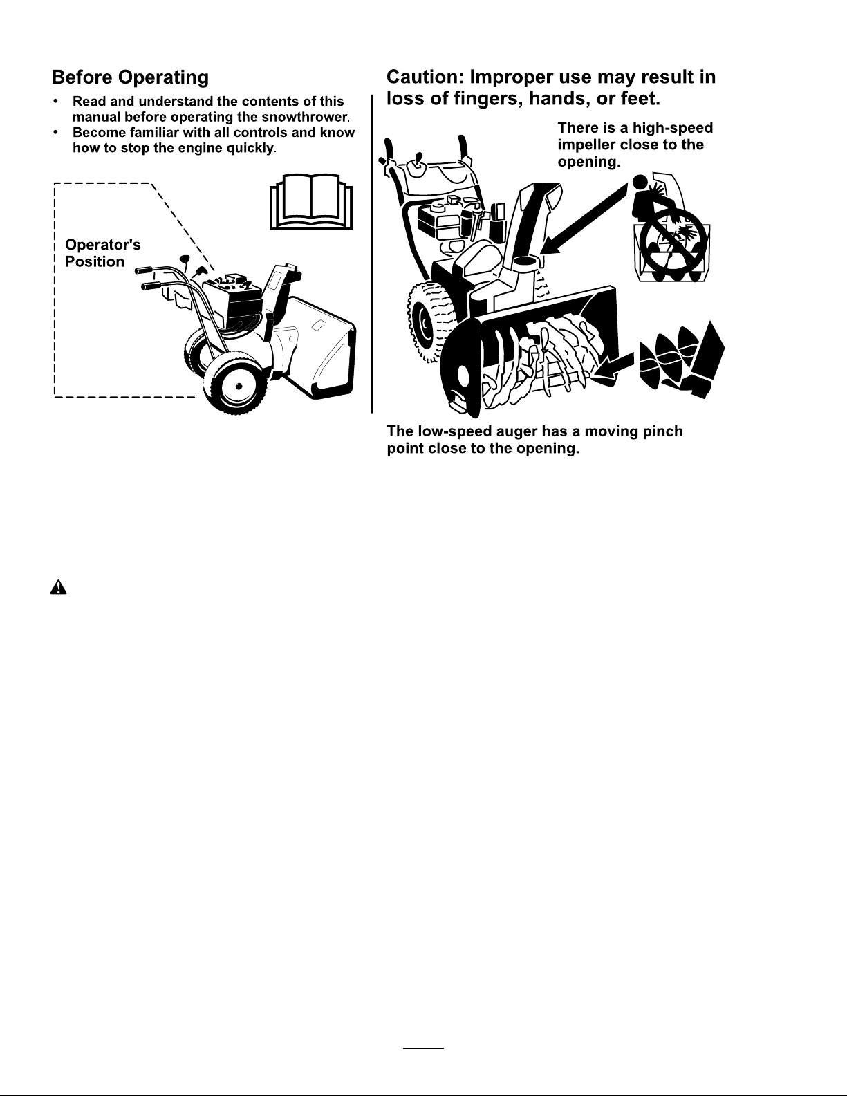
BeforeOperating
?
?
Readandunderstandthecontentsofthis
manualbeforeoperatingthesnowthrower .
Becomefamiliarwithallcontrolsandknow
howtostoptheenginequickly .
Operator 's
Position
Thelow-speedaugerhasamovingpinch
pointclosetotheopening.
Caution:Improperusemayresultin
lossoffingers,hands,orfeet.
Thereisahigh-speed
impellerclosetothe
opening.
ThissnowthrowermeetsorexceedstheISO
standard8437ineffectatthetimeofproduction.
Readandunderstandthecontentsofthismanual
beforetheengineiseverstarted.
Thisisthesafetyalertsymbol.Itisusedtoalert
youtopotentialpersonalinjuryhazards.Obeyall
safetymessagesthatfollowthissymboltoavoid
possibleinjuryordeath.
Improperlyusingormaintainingthissnowthrower
couldresultininjuryordeath.Toreducethis
potential,complywiththefollowingsafety
instructions.
Training
•Readtheoperatingandserviceinstructionmanual
carefully.Bethoroughlyfamiliarwiththecontrols
andtheproperuseoftheequipment.Knowhowto
stoptheunitanddisengagethecontrolsquickly.
•Neverallowchildrentooperatetheequipment.
Neverallowadultstooperatetheequipmentwithout
properinstruction.
•Keeptheareaofoperationclearofallpersons,
particularlysmallchildren,andpets.
Preparation
•Thoroughlyinspecttheareawheretheequipmentis
tobeusedandremovealldoormats,sleds,boards,
wires,andotherforeignobjects.
•Disengageallclutchesandshiftintoneutralbefore
startingtheengine.
•Donotoperatetheequipmentwithoutwearing
adequatewintergarments.Wearfootwearwhichwill
improvefootingonslipperysurfaces.
•Handlefuelwithcare;itishighlyammable.
–Useanapprovedfuelcontainer.
–Neveraddfueltoarunningorhotengine.
–Fillfueltankoutdoorswithextremecare.Never
–Replacegasolinecapssecurelyandwipeup
•Adjustthecollectorhousingheighttocleargravel
orcrushedrocksurface.
•Neverattempttomakeanyadjustmentswhile
theengineisrunning(exceptwherespecically
recommendedbymanufacturer).
•Letengineandmachineadjusttooutdoor
temperaturesbeforestartingtoclearsnow.
llfueltankindoors.
spilledfuel.
•Exercisecautiontoavoidslippingorfalling,
especiallywhenoperatinginreverse.
•Theoperationofanypoweredmachinecanresultin
foreignobjectsbeingthrownintotheeyes.Always
2

wearsafetyglassesoreyeshieldsduringoperationor
whileperforminganadjustmentorrepair.
•Useonlyattachmentsandaccessoriesapprovedby
themanufacturerofsnowthrower(suchaswheel
weights,counterweights,cabs,etc.).
Operation
•Donotputhandsorfeetnearorunderrotatingparts.
Keepclearofthedischargeopeningatalltimes.
•Exerciseextremecautionwhenoperatingonor
crossinggraveldrives,walks,orroads.Stayalertfor
hiddenhazardsortrafc.
•Afterstrikingaforeignobject,stoptheengine,
removethewirefromthespark-plug,thoroughly
inspectthesnowthrowerforanydamage,andrepair
thedamagebeforerestartingandoperatingthesnow
thrower.
•Iftheunitshouldstarttovibrateabnormally,stop
theengineandcheckimmediatelyforthecause.
Vibrationisgenerallyawarningoftrouble.
•Stoptheenginewheneveryouleavetheoperating
position,beforeuncloggingthecollector/impeller
housingordischargeguide,andwhenmakingany
repairs,adjustments,orinspections.
•Whencleaning,repairing,orinspecting,makecertain
thecollector/impellerandallmovingpartshave
stopped.Disconnectthespark-plugwire,andkeep
thewireawayfromtheplugtopreventaccidental
starting.
•Donotruntheengineindoors,exceptwhenstarting
itandformovingthesnowthrowerinoroutofthe
building.Opentheoutsidedoors;exhaustfumes
aredangerous.
•Donotclearsnowacrossthefaceofslopes.Exercise
extremecautionwhenchangingdirectiononslopes.
Donotattempttoclearsteepslopes.
•Neveroperatethesnowthrowerwithoutproper
guards,plates,orothersafetyprotectivedevicesin
place.
•Neveroperatethesnowthrowernearglass
enclosures,automobiles,windowwells,drop-offs,
etc.withoutproperadjustmentofthesnow
dischargeangle.Keepchildrenandpetsaway .
•Donotoverloadthemachinecapacitybyattempting
toclearsnowattoofastarate.
•Neveroperatethemachineathightransportspeeds
onslipperysurfaces.Usecarewhenreversing.
•Neverdirectdischargeatbystandersorallowanyone
infrontoftheunit.
•Disengagepowertothecollector/impellerwhen
snowthroweristransportedornotinuse.
•Neveroperatethesnowthrowerwithoutgood
visibilityorlight.Alwaysbesureofyourfooting,and
keeparmholdonthehandles.Walk;neverrun.
•Neveroperatethesnowthrowerwithoutgood
visibilityorlight.
•Takeallpossibleprecautionswhenleavingthe
machineunattended.Shiftintoneutral,setthe
parkingbrake,stoptheengineandremovethekey.
MaintenanceandStorage
•Checkallfastenersatfrequentintervalsforproper
tightnesstobesuretheequipmentisinsafeworking
condition.
•Neverstorethemachinewithfuelinthefueltank
insideabuildingwhereignitionsourcesarepresent
suchashotwaterandspaceheaters,clothesdryers,
etc.Allowtheenginetocoolbeforestoringinany
enclosure.
•Alwaysrefertoowner’sguideinstructionsfor
importantdetailsifthesnowthroweristobestored
foranextendedperiod.
•Maintainorreplacesafetyandinstructionslabels,
asnecessary.
•Runthemachineafewminutesafterthrowingsnow
topreventfreeze-upofthecollector/impeller.
ToroSnowthrowerSafety
Thefollowinglistcontainssafetyinformationspecic
toToroproductsorothersafetyinformationthatyou
mustknow.
•Rotatingrotorbladescaninjurengersor
hands.Staybehindthehandlesandawayfromthe
dischargeopeningwhileoperatingthesnowthrower.
Keepyourface,hands,feet,andanyotherpart
ofyourbodyorclothingawayfrommovingor
rotatingparts.
•Beforeadjusting,cleaning,repairing,andinspecting
thesnowthrower,andbeforeuncloggingthe
dischargechute,stoptheengine,removethekey,
andwaitforallmovingpartstostop.
•Usethecleanouttool,notyourhands,toremove
obstructionsfromthedischargechute.
•Beforeleavingtheoperatingposition,stopthe
engine,removethekey,andwaitforallmovingparts
tostop.
3
•Donotwearloose-ttingclothingthatcouldget
caughtinmovingparts.
container.Removethekeyfromtheignitionswitch
beforestoringthesnowthrower.
•Ifashield,safetydevice,ordecalisdamaged,
illegible,orlost,repairorreplaceitbeforebeginning
operation.Also,tightenanyloosefasteners.
•Donotsmokewhilehandlinggasoline.
•Donotusethesnowthroweronaroof.
•Donottouchtheenginewhileitisrunningorsoon
afterithasstoppedbecausetheenginemaybehot
enoughtocauseaburn.
•Performonlythosemaintenanceinstructions
describedinthismanual.Beforeperformingany
maintenance,service,oradjustment,stoptheengine,
removethekey,anddisconnectthewirefromthe
sparkplug.Ifmajorrepairsareeverneeded,contact
anAuthorizedServiceDealer.
•Donotchangethegovernorsettingsontheengine.
•Whenstoringthesnowthrowerformorethan30
days,drainthefuelfromthefueltanktoprevent
apotentialhazard.Storefuelinanapprovedfuel
•PurchaseonlygenuineTororeplacementpartsand
accessories.
SoundPressure
Thisunithasamaximumsoundpressurelevelatthe
operator’searof95dBA,basedonmeasurementsof
identicalmachinesperEN11201.
SoundPower
Thisunithasaguaranteedsoundpowerlevelof108
dBA,basedonmeasurementsofidenticalmachinesper
EN3744.
Vibration
Thisunitdoesnotexceedahand/armvibrationlevelof
3.1m/s
perEN1033.
2
,basedonmeasurementsofidenticalmachines
SafetyandInstructionalDecals
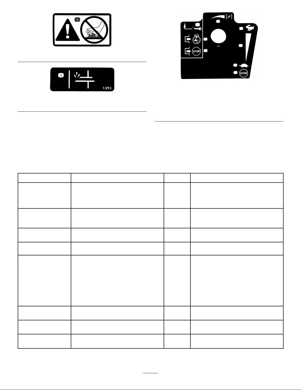
Important:Safetyandinstructiondecalsarelocatednearareasofpotentialdanger.Replacedamaged
decals.
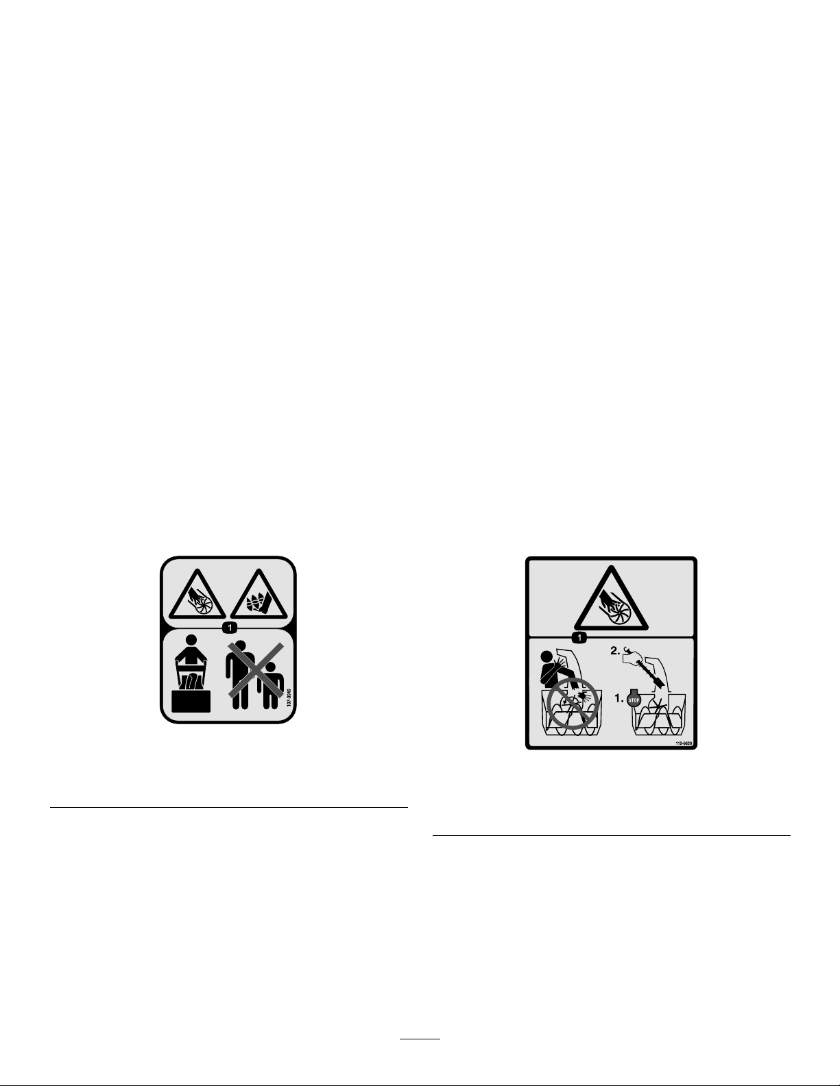
107-3040
1.Cuttingdismemberment,impellerandcutting
dismemberment,augerhazards—keepbystandersasafe
distancefromthesnowthrower.
1.Cutting/dismembermenthazard,impeller—donotplace
yourhandinthechute;stoptheenginebeforeleavingthe
operator’sposition,usethetooltoclearthechute.
112-6620
4
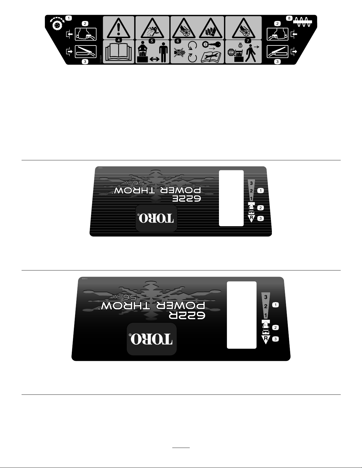
112-6624
1.Wheeldrive3.Disengage5.Thrownobject
2.Engage4.Warning—readthe
Operator’sManual.
hazard—keepbystanders
asafedistancefromthe
snowthrower.
6.Cutting/dismemberment
hazard,impeller—keep
awayfrommovingparts;
removetheignitionkeyand
readtheinstructionsbefore
servicingorperforming
maintenance.
7.Cutting/dismemberment
hazard,impeller—stop
theengineandwaitforall
movingpartstostopbefore
leavingtheoperator’s
position.
8.Auger
1.Forwarddrivespeedsettings
1.Forwarddrivespeedsettings
2.Speedselector
2.Speedselector
112-6637
Model38607only
3.Reversedrivespeedsetting
112-6638
Model38606only
3.Reversedrivespeedsetting
5
1.Warning—hotsurface,donottouch
1
2
3
4
5
6
5
7
TecumsehPartNo.36501
1.Primer
Setup
LooseParts
Usethechartbelowtoverifythatallpartshavebeenshipped.
TecumsehPartNo.35077
1.Keyignition5.Increasingscale
2.Engagetostarttheengine
3.Disengagetostopthe
engine
4.Fast
6.Slow
7.Stoptheengine
ProcedureDescription
1.
2.
3.
4.
5.
6.
Qty.
Handle1
Bolts4
Bellevillewashers4
Flangenut1
Speedselectorrod
Cotterpin
Flatwasher1
Flangelocknut1Installthetractionrod.
Clevispin
Cotterpin
Chutecontrolrodassembly(rodand
bracket,wormgear,andbracket)
Bellevillewasher1
Bolt2
Carriagebolt
Locknut3
Curvedwasher
Flatwasher1
Nopartsrequired
1
1
1
1
1
1
1
–
Installthehandle.
Installthespeedselectorrod.
Installtheauger/impellerdrivecontrol
linkage.
Installthechutecontrolrod.
Filltheenginewithoil.
Use
7.
8.
Nopartsrequired
Nopartsrequired
6
–
–
Checkthetirepressure.
Checktheskidsandscraper.
1.InstallingtheHandle
1Handle
4Bolts
4Bellevillewashers
1Flangenut
Procedure
1.Removethetiestrapsthatsecurethecontrolrods
tothehandle.
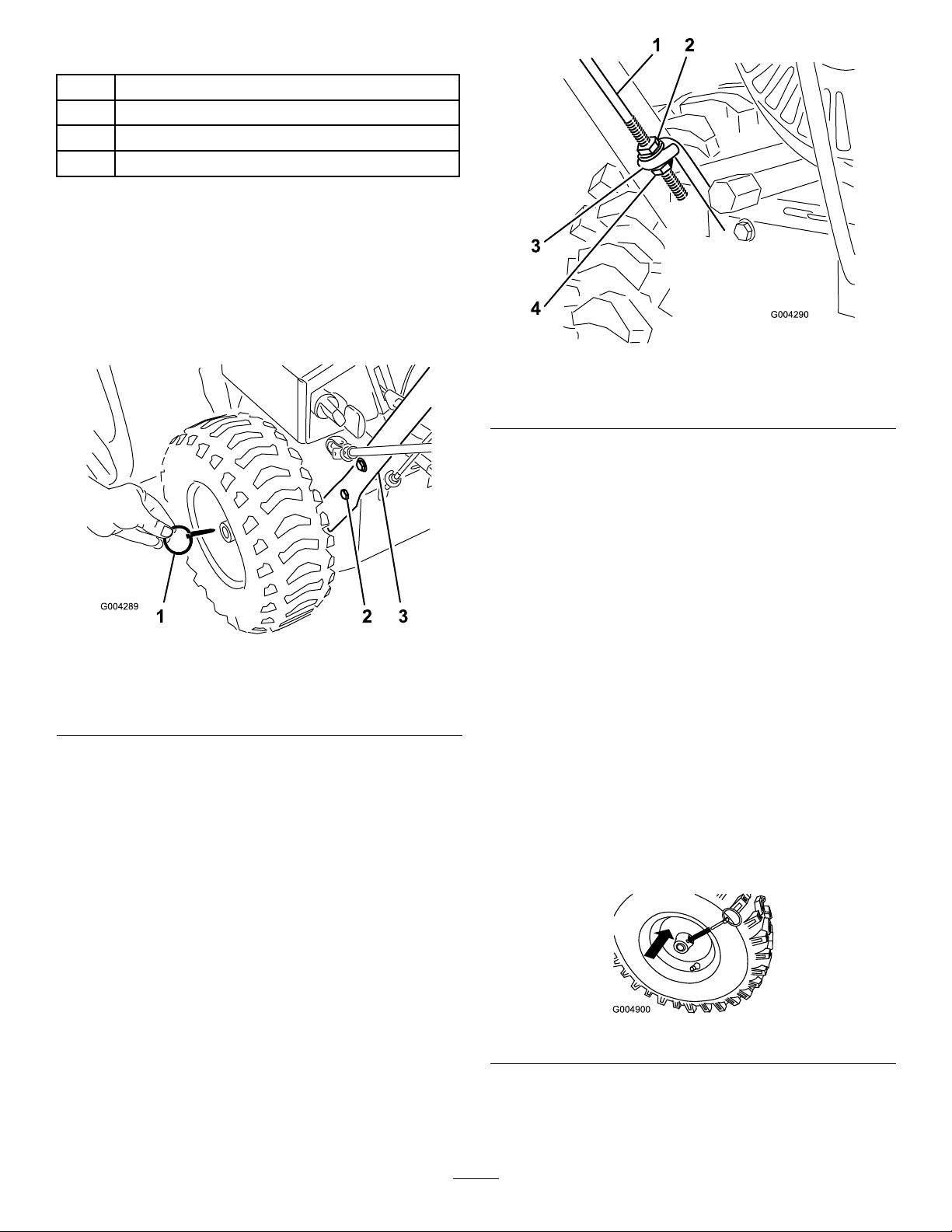
2.Removetheaxlepinsfrombothwheelsandslide
thewheelsoutwardontheaxleapproximately1inch
(2.5cm)(Figure3).
Figure4
1.Tractionrod3.Lowertractionrodloop
2.Flangenut4.Flangelocknut
4.Positiontheleftsideofthehandleassemblyagainst
thesideofthesnowthrowerandinserttheendof
thetractionrodthroughthelowertractionrodloop
(Figure4).
Figure3
1.Axlepin(2)
2.CapscrewandBelleville
washer(4)
3.Handle
3.Threadaangenut(nottheangelocknut)withthe
angedownontothetractionrodattachedtothe
leftsideofthehandle(Figure4).
5.Aligntheholesintheleftsideofthehandleassembly
withtheholesintheleftsideplate,andsecurethe
handlewith2capscrewsandBellevillewashersuntil
theyarengertight(Figure3).
Note:TheconcavesideoftheBellevillewasher
goesagainsttheoutsideofthehandle.
6.Aligntheholesintherightsideofthehandle
assemblywiththeholesintherightsideplate,and
securethehandlewith2capscrewsandBelleville
washersuntiltheyarengertight.
7.Ensurethatthehandlesareatthesameheight,then
tightenthehandlefastenerssecurely .
8.Slidethewheelsinwardandinserteachaxlepin
throughtheholeineachwheelhubandthroughthe
outerholeoftheaxle(Figure5).
Figure5
Note:Tousetirechains(optional),installtheaxle
pinsthroughtheouteraxleholes.
7
2.InstallingtheSpeedSelector
Rod
1
Speedselectorrod
1
Cotterpin
1Flatwasher
Procedure
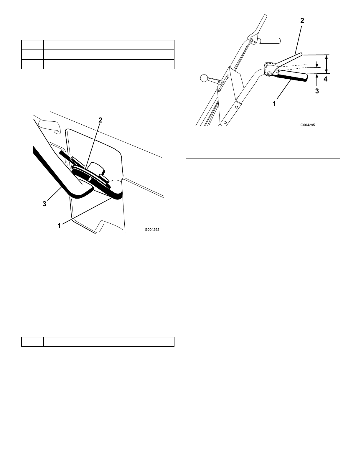
1.Pullthespeedselectorarm(Figure6)tothemost
outwardposition.
Figure7
1.Handgrip
2.Tractioncontrollever
3.1to2inches(2.5to5cm)
4.4-1/2inches(11.4cm)
3.Tightenthe2angenutsuntiltheyarengertight.
4.Movethespeedselectorlever(Figure7)intothird
gear.
Figure6
1.Speedselectorarm3.Speedselectorrod
2.Flatwasherandcotterpin
2.Movethespeedselectorlever(Figure13)onthe
controlpaneltotheR(Reverse)position.
3.Installthespeedselectorrodintothespeedselector
arm,addaatwasherontheselectorrod,andsecure
itwithacotterpin(Figure6).
3.InstallingtheTractionRod
1Flangelocknut
Procedure
Note:Ifthespeedselectorleverdoesnotmove
intothirdgear,adjustthespeedselectorbefore
continuing.RefertoAdjustingtheSpeedSelector.
5.Slowlypullthesnowthrowerbackwardwhileslowly
pressingthetractioncontrollevertowardthe
handgrip.
Note:Theadjustmentiscorrectwhenthewheels
stoprollingbackwardandthedistancebetweenthe
topofthehandgripandthebottomofthetraction
controlleveris1to2inches(2.5to5cm)asshown
inFigure7.
6.Adjustthe2angenuts,ifnecessary,toobtainthe
properdistancebetweenthetopofthehandgripand
thebottomofthetractioncontrollever.
7.Tightentheangenutssecurely.
1.Threadtheangelocknut(angesideup)ontothe
bottomofthetractioncontrolrod,belowtheloop
inthelowertractionrod(Figure4).
2.Adjustthe2angenutsupordownonthetraction
roduntilthedistancebetweenthetopofthe
handgripandthebottomofthetractioncontrol
leverisapproximately4-1/2inches(11.4cm)as
showninFigure7.
8
4.InstallingtheAuger/Impeller
DriveControlLinkage
1
Clevispin
1
Cotterpin
Procedure
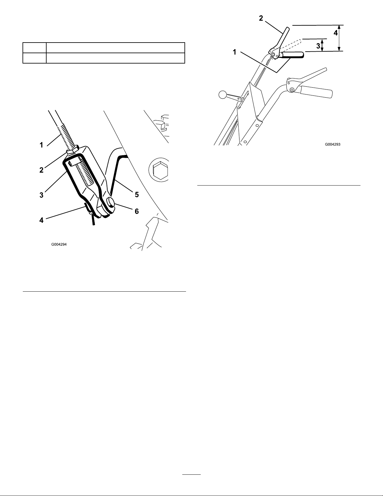
1.Loosenthejamnutabovetheclevisontheupper
controlrod(Figure8).
Figure9
1.Handgrip
2.Auger/impellercontrol
lever
3.1to2inches(2.5to5cm)
4.5inches(12.7cm)
Note:Thedistanceshouldbeapproximately5
inches(12.7cm).
Figure8
1.Uppercontrolrod
2.Jamnut5.Lowercontrolrod
3.Clevis6.Clevispin
4.Cotterpin
2.Aligntheholesintheclevisandthelowercontrol
rodandinserttheclevispin(Figure8).
3.Checkthedistancebetweenthetopofthehandgrip
andthebottomoftheauger/impellerdrivecontrol
lever(Figure9).
4.Presstheauger/impellerdrivecontrolleverslowly
towardthehandgrip.
Note:Theamountofforceneededtocompressthe
leverincreasesnoticeablywhenyouremovetheslack
fromtheauger/impellerdrivebelt(approximately
1/2ofthelevermovement).Theadjustmentis
correctwhentheforcebeginstoincreaseandthe
distancebetweenthetopofthehandgripandthe
bottomoftheauger/impellerdrivecontrolleveris1
to2inches(2.5to5cm)asshowninFigure9.
Note:Iftheforcedoesnotnoticeablyincrease,
removethebeltcover(refertostep2ofReplacing
theTractionDriveBelt)andmeasure2inches(5cm)
abovethehandgripatthepointwhereyouremove
theslackfromtheauger/impellerdrivebelt.
5.Toadjustthedistance:
A.Removetheclevispin.
B.Loosenthejamnut.
C.Threadtheclevisupordowntoincreaseor
decreasethedistancebetweenthetopofthe
handgripandthebottomoftheauger/impeller
drivecontrollever(Figure8).
6.Whentheadjustmentiscorrect,installtheclevispin
andsecureitinplacewiththecotterpin(Figure8).
7.Tightenthejamnuttosecuretheclevis(Figure8).
9
 Loading...