

Page 1
622Rand622EPowerThrow
ModelNo.38606—SerialNo.270000001andUp
ModelNo.38607—SerialNo.270000001andUp
FormNo.3355-529RevG
®
Snowthrowers
Operator'sManual
Introduction
Readthisinformationcarefullytolearnhowtooperate
andmaintainyourproductproperlyandtoavoidinjury
andproductdamage.Youareresponsibleforoperating
theproductproperlyandsafely.
YoumaycontactTorodirectlyatwww.Toro.comfor
productandaccessoryinformation,helpndinga
dealer,ortoregisteryourproduct.
Wheneveryouneedservice,genuineToroparts,or
additionalinformation,contactanAuthorizedService
DealerorToroCustomerServiceandhavethemodel
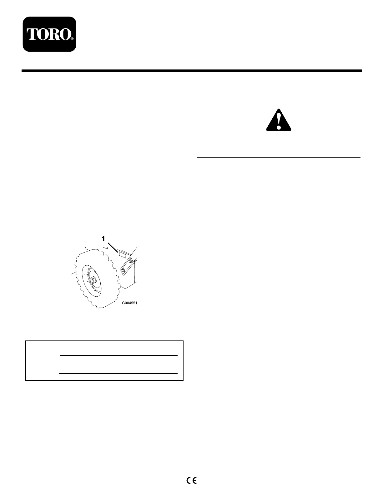
andserialnumbersofyourproductready.Figure1
identiesthelocationofthemodelandserialnumbers
ontheproduct.Writethenumbersinthespace
provided.
injuryordeathifyoudonotfollowtherecommended
precautions.
Figure2
1.Safetyalertsymbol
Thismanualuses2wordstohighlightinformation.
Importantcallsattentiontospecialmechanical
informationandNoteemphasizesgeneralinformation
worthyofspecialattention.
ReplacementEngineOwner’sManualsmaybe
orderedthroughtheenginemanufacturer.
Figure1
1.Modelandserialnumberlocation
ModelNo.
SerialNo.
Thismanualidentiespotentialhazardsandhas
safetymessagesidentiedbythesafetyalertsymbol
(Figure2),whichsignalsahazardthatmaycauseserious
©2008—TheT oro®Company
8111LyndaleAvenueSouth
Bloomington,MN55420
Registeratwww.Toro.com.
OriginalInstructions(EN)
PrintedintheUSA
AllRightsReserved
Page 2
Safety
BeforeOperating
?
?
Readandunderstandthecontentsofthis
manualbeforeoperatingthesnowthrower .
Becomefamiliarwithallcontrolsandknow
howtostoptheenginequickly .
Operator 's
Position
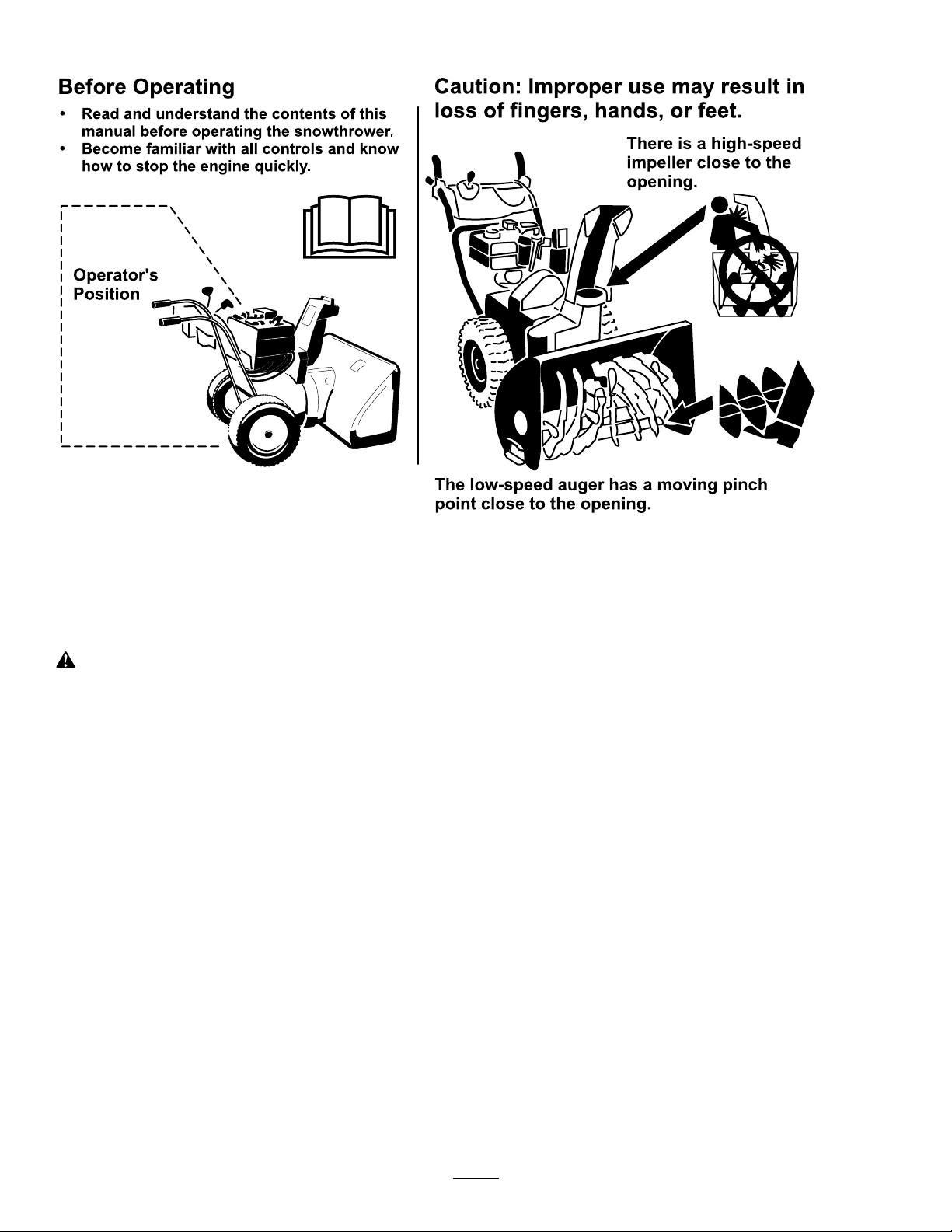
Thelow-speedaugerhasamovingpinch
pointclosetotheopening.
Caution:Improperusemayresultin
lossoffingers,hands,orfeet.
Thereisahigh-speed
impellerclosetothe
opening.
ThissnowthrowermeetsorexceedstheISO
standard8437ineffectatthetimeofproduction.
Readandunderstandthecontentsofthismanual
beforetheengineiseverstarted.
Thisisthesafetyalertsymbol.Itisusedtoalert
youtopotentialpersonalinjuryhazards.Obeyall
safetymessagesthatfollowthissymboltoavoid
possibleinjuryordeath.
Improperlyusingormaintainingthissnowthrower
couldresultininjuryordeath.Toreducethis
potential,complywiththefollowingsafety
instructions.
Training
•Readtheoperatingandserviceinstructionmanual
carefully.Bethoroughlyfamiliarwiththecontrols
andtheproperuseoftheequipment.Knowhowto
stoptheunitanddisengagethecontrolsquickly.
•Neverallowchildrentooperatetheequipment.
Neverallowadultstooperatetheequipmentwithout
properinstruction.
•Keeptheareaofoperationclearofallpersons,
particularlysmallchildren,andpets.
Preparation
•Thoroughlyinspecttheareawheretheequipmentis
tobeusedandremovealldoormats,sleds,boards,
wires,andotherforeignobjects.
•Disengageallclutchesandshiftintoneutralbefore
startingtheengine.
•Donotoperatetheequipmentwithoutwearing
adequatewintergarments.Wearfootwearwhichwill
improvefootingonslipperysurfaces.
•Handlefuelwithcare;itishighlyammable.
–Useanapprovedfuelcontainer.
–Neveraddfueltoarunningorhotengine.
–Fillfueltankoutdoorswithextremecare.Never
–Replacegasolinecapssecurelyandwipeup
•Adjustthecollectorhousingheighttocleargravel
orcrushedrocksurface.
•Neverattempttomakeanyadjustmentswhile
theengineisrunning(exceptwherespecically
recommendedbymanufacturer).
•Letengineandmachineadjusttooutdoor
temperaturesbeforestartingtoclearsnow.
llfueltankindoors.
spilledfuel.
•Exercisecautiontoavoidslippingorfalling,
especiallywhenoperatinginreverse.
•Theoperationofanypoweredmachinecanresultin
foreignobjectsbeingthrownintotheeyes.Always
2
Page 3

wearsafetyglassesoreyeshieldsduringoperationor
whileperforminganadjustmentorrepair.
•Useonlyattachmentsandaccessoriesapprovedby
themanufacturerofsnowthrower(suchaswheel
weights,counterweights,cabs,etc.).
Operation
•Donotputhandsorfeetnearorunderrotatingparts.
Keepclearofthedischargeopeningatalltimes.
•Exerciseextremecautionwhenoperatingonor
crossinggraveldrives,walks,orroads.Stayalertfor
hiddenhazardsortrafc.
•Afterstrikingaforeignobject,stoptheengine,
removethewirefromthespark-plug,thoroughly
inspectthesnowthrowerforanydamage,andrepair
thedamagebeforerestartingandoperatingthesnow
thrower.
•Iftheunitshouldstarttovibrateabnormally,stop
theengineandcheckimmediatelyforthecause.
Vibrationisgenerallyawarningoftrouble.
•Stoptheenginewheneveryouleavetheoperating
position,beforeuncloggingthecollector/impeller
housingordischargeguide,andwhenmakingany
repairs,adjustments,orinspections.
•Whencleaning,repairing,orinspecting,makecertain
thecollector/impellerandallmovingpartshave
stopped.Disconnectthespark-plugwire,andkeep
thewireawayfromtheplugtopreventaccidental
starting.
•Donotruntheengineindoors,exceptwhenstarting
itandformovingthesnowthrowerinoroutofthe
building.Opentheoutsidedoors;exhaustfumes
aredangerous.
•Donotclearsnowacrossthefaceofslopes.Exercise
extremecautionwhenchangingdirectiononslopes.
Donotattempttoclearsteepslopes.
•Neveroperatethesnowthrowerwithoutproper
guards,plates,orothersafetyprotectivedevicesin
place.
•Neveroperatethesnowthrowernearglass
enclosures,automobiles,windowwells,drop-offs,
etc.withoutproperadjustmentofthesnow
dischargeangle.Keepchildrenandpetsaway .
•Donotoverloadthemachinecapacitybyattempting
toclearsnowattoofastarate.
•Neveroperatethemachineathightransportspeeds
onslipperysurfaces.Usecarewhenreversing.
•Neverdirectdischargeatbystandersorallowanyone
infrontoftheunit.
•Disengagepowertothecollector/impellerwhen
snowthroweristransportedornotinuse.
•Neveroperatethesnowthrowerwithoutgood
visibilityorlight.Alwaysbesureofyourfooting,and
keeparmholdonthehandles.Walk;neverrun.
•Neveroperatethesnowthrowerwithoutgood
visibilityorlight.
•Takeallpossibleprecautionswhenleavingthe
machineunattended.Shiftintoneutral,setthe
parkingbrake,stoptheengineandremovethekey.
MaintenanceandStorage
•Checkallfastenersatfrequentintervalsforproper
tightnesstobesuretheequipmentisinsafeworking
condition.
•Neverstorethemachinewithfuelinthefueltank
insideabuildingwhereignitionsourcesarepresent
suchashotwaterandspaceheaters,clothesdryers,
etc.Allowtheenginetocoolbeforestoringinany
enclosure.
•Alwaysrefertoowner’sguideinstructionsfor
importantdetailsifthesnowthroweristobestored
foranextendedperiod.
•Maintainorreplacesafetyandinstructionslabels,
asnecessary.
•Runthemachineafewminutesafterthrowingsnow
topreventfreeze-upofthecollector/impeller.
ToroSnowthrowerSafety
Thefollowinglistcontainssafetyinformationspecic
toToroproductsorothersafetyinformationthatyou
mustknow.
•Rotatingrotorbladescaninjurengersor
hands.Staybehindthehandlesandawayfromthe
dischargeopeningwhileoperatingthesnowthrower.
Keepyourface,hands,feet,andanyotherpart
ofyourbodyorclothingawayfrommovingor
rotatingparts.
•Beforeadjusting,cleaning,repairing,andinspecting
thesnowthrower,andbeforeuncloggingthe
dischargechute,stoptheengine,removethekey,
andwaitforallmovingpartstostop.
•Usethecleanouttool,notyourhands,toremove
obstructionsfromthedischargechute.
•Beforeleavingtheoperatingposition,stopthe
engine,removethekey,andwaitforallmovingparts
tostop.
3
Page 4
•Donotwearloose-ttingclothingthatcouldget
caughtinmovingparts.
container.Removethekeyfromtheignitionswitch
beforestoringthesnowthrower.
•Ifashield,safetydevice,ordecalisdamaged,
illegible,orlost,repairorreplaceitbeforebeginning
operation.Also,tightenanyloosefasteners.
•Donotsmokewhilehandlinggasoline.
•Donotusethesnowthroweronaroof.
•Donottouchtheenginewhileitisrunningorsoon
afterithasstoppedbecausetheenginemaybehot
enoughtocauseaburn.
•Performonlythosemaintenanceinstructions
describedinthismanual.Beforeperformingany
maintenance,service,oradjustment,stoptheengine,
removethekey,anddisconnectthewirefromthe
sparkplug.Ifmajorrepairsareeverneeded,contact
anAuthorizedServiceDealer.
•Donotchangethegovernorsettingsontheengine.
•Whenstoringthesnowthrowerformorethan30
days,drainthefuelfromthefueltanktoprevent
apotentialhazard.Storefuelinanapprovedfuel
•PurchaseonlygenuineTororeplacementpartsand
accessories.
SoundPressure
Thisunithasamaximumsoundpressurelevelatthe
operator’searof95dBA,basedonmeasurementsof
identicalmachinesperEN11201.
SoundPower
Thisunithasaguaranteedsoundpowerlevelof108
dBA,basedonmeasurementsofidenticalmachinesper
EN3744.
Vibration
Thisunitdoesnotexceedahand/armvibrationlevelof
3.1m/s
perEN1033.
2
,basedonmeasurementsofidenticalmachines
SafetyandInstructionalDecals
Important:Safetyandinstructiondecalsarelocatednearareasofpotentialdanger.Replacedamaged
decals.
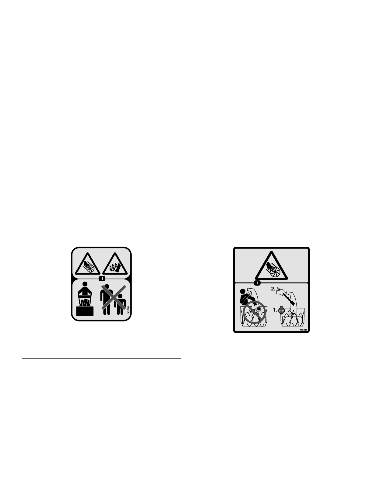
107-3040
1.Cuttingdismemberment,impellerandcutting
dismemberment,augerhazards—keepbystandersasafe
distancefromthesnowthrower.
1.Cutting/dismembermenthazard,impeller—donotplace
yourhandinthechute;stoptheenginebeforeleavingthe
operator’sposition,usethetooltoclearthechute.
112-6620
4
Page 5
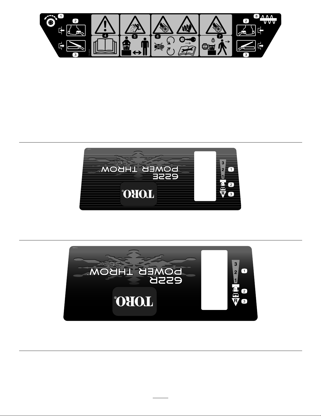
112-6624
1.Wheeldrive3.Disengage5.Thrownobject
2.Engage4.Warning—readthe
Operator’sManual.
hazard—keepbystanders
asafedistancefromthe
snowthrower.
6.Cutting/dismemberment
hazard,impeller—keep
awayfrommovingparts;
removetheignitionkeyand
readtheinstructionsbefore
servicingorperforming
maintenance.
7.Cutting/dismemberment
hazard,impeller—stop
theengineandwaitforall
movingpartstostopbefore
leavingtheoperator’s
position.
8.Auger
1.Forwarddrivespeedsettings
1.Forwarddrivespeedsettings
2.Speedselector
2.Speedselector
112-6637
Model38607only
3.Reversedrivespeedsetting
112-6638
Model38606only
3.Reversedrivespeedsetting
5
Page 6
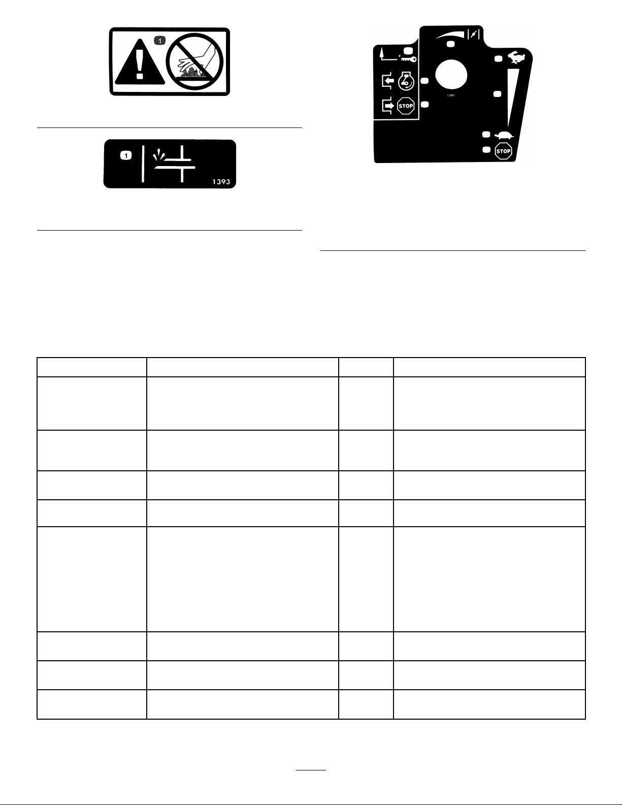
1.Warning—hotsurface,donottouch
1
2
3
4
5
6
5
7
TecumsehPartNo.36501
1.Primer
Setup
LooseParts
Usethechartbelowtoverifythatallpartshavebeenshipped.
TecumsehPartNo.35077
1.Keyignition5.Increasingscale
2.Engagetostarttheengine
3.Disengagetostopthe
engine
4.Fast
6.Slow
7.Stoptheengine
ProcedureDescription
1.
2.
3.
4.
5.
6.
Qty.
Handle1
Bolts4
Bellevillewashers4
Flangenut1
Speedselectorrod
Cotterpin
Flatwasher1
Flangelocknut1Installthetractionrod.
Clevispin
Cotterpin
Chutecontrolrodassembly(rodand
bracket,wormgear,andbracket)
Bellevillewasher1
Bolt2
Carriagebolt
Locknut3
Curvedwasher
Flatwasher1
Nopartsrequired
1
1
1
1
1
1
1
–
Installthehandle.
Installthespeedselectorrod.
Installtheauger/impellerdrivecontrol
linkage.
Installthechutecontrolrod.
Filltheenginewithoil.
Use
7.
8.
Nopartsrequired
Nopartsrequired
6
–
–
Checkthetirepressure.
Checktheskidsandscraper.
Page 7
1.InstallingtheHandle
1Handle
4Bolts
4Bellevillewashers
1Flangenut
Procedure
1.Removethetiestrapsthatsecurethecontrolrods
tothehandle.
2.Removetheaxlepinsfrombothwheelsandslide
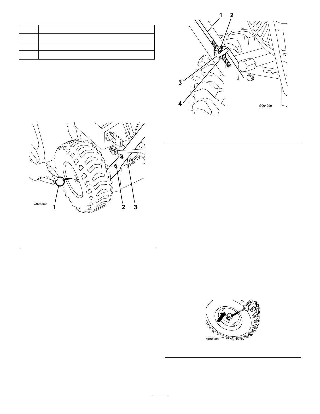
thewheelsoutwardontheaxleapproximately1inch
(2.5cm)(Figure3).
Figure4
1.Tractionrod3.Lowertractionrodloop
2.Flangenut4.Flangelocknut
4.Positiontheleftsideofthehandleassemblyagainst
thesideofthesnowthrowerandinserttheendof
thetractionrodthroughthelowertractionrodloop
(Figure4).
Figure3
1.Axlepin(2)
2.CapscrewandBelleville
washer(4)
3.Handle
3.Threadaangenut(nottheangelocknut)withthe
angedownontothetractionrodattachedtothe
leftsideofthehandle(Figure4).
5.Aligntheholesintheleftsideofthehandleassembly
withtheholesintheleftsideplate,andsecurethe
handlewith2capscrewsandBellevillewashersuntil
theyarengertight(Figure3).
Note:TheconcavesideoftheBellevillewasher
goesagainsttheoutsideofthehandle.
6.Aligntheholesintherightsideofthehandle
assemblywiththeholesintherightsideplate,and
securethehandlewith2capscrewsandBelleville
washersuntiltheyarengertight.
7.Ensurethatthehandlesareatthesameheight,then
tightenthehandlefastenerssecurely .
8.Slidethewheelsinwardandinserteachaxlepin
throughtheholeineachwheelhubandthroughthe
outerholeoftheaxle(Figure5).
Figure5
Note:Tousetirechains(optional),installtheaxle
pinsthroughtheouteraxleholes.
7
Page 8
2.InstallingtheSpeedSelector
Rod
1
Speedselectorrod
1
Cotterpin
1Flatwasher
Procedure
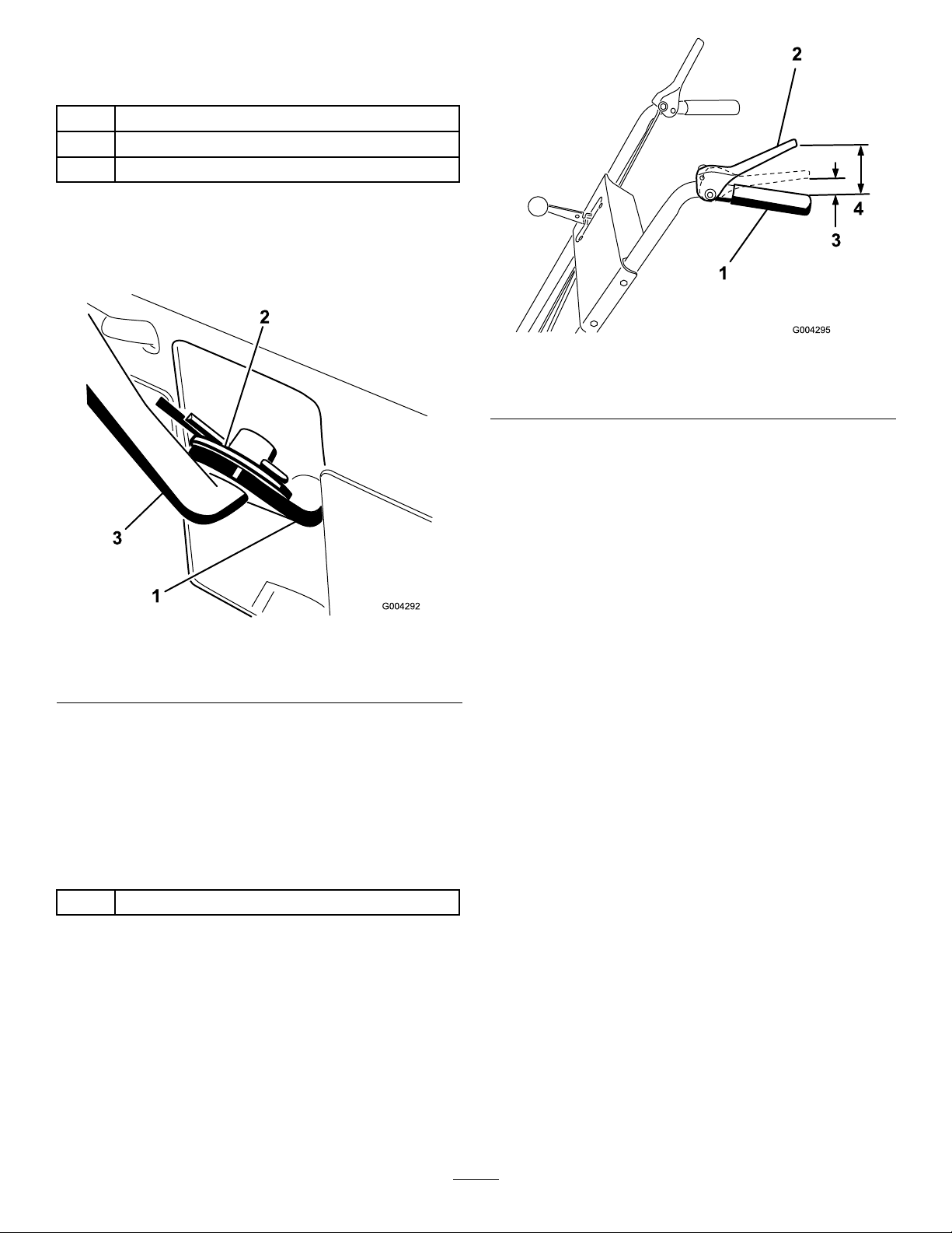
1.Pullthespeedselectorarm(Figure6)tothemost
outwardposition.
Figure7
1.Handgrip
2.Tractioncontrollever
3.1to2inches(2.5to5cm)
4.4-1/2inches(11.4cm)
3.Tightenthe2angenutsuntiltheyarengertight.
4.Movethespeedselectorlever(Figure7)intothird
gear.
Figure6
1.Speedselectorarm3.Speedselectorrod
2.Flatwasherandcotterpin
2.Movethespeedselectorlever(Figure13)onthe
controlpaneltotheR(Reverse)position.
3.Installthespeedselectorrodintothespeedselector
arm,addaatwasherontheselectorrod,andsecure
itwithacotterpin(Figure6).
3.InstallingtheTractionRod
1Flangelocknut
Procedure
Note:Ifthespeedselectorleverdoesnotmove
intothirdgear,adjustthespeedselectorbefore
continuing.RefertoAdjustingtheSpeedSelector.
5.Slowlypullthesnowthrowerbackwardwhileslowly
pressingthetractioncontrollevertowardthe
handgrip.
Note:Theadjustmentiscorrectwhenthewheels
stoprollingbackwardandthedistancebetweenthe
topofthehandgripandthebottomofthetraction
controlleveris1to2inches(2.5to5cm)asshown
inFigure7.
6.Adjustthe2angenuts,ifnecessary,toobtainthe
properdistancebetweenthetopofthehandgripand
thebottomofthetractioncontrollever.
7.Tightentheangenutssecurely.
1.Threadtheangelocknut(angesideup)ontothe
bottomofthetractioncontrolrod,belowtheloop
inthelowertractionrod(Figure4).
2.Adjustthe2angenutsupordownonthetraction
roduntilthedistancebetweenthetopofthe
handgripandthebottomofthetractioncontrol
leverisapproximately4-1/2inches(11.4cm)as
showninFigure7.
8
Page 9
4.InstallingtheAuger/Impeller
DriveControlLinkage
1
Clevispin
1
Cotterpin
Procedure
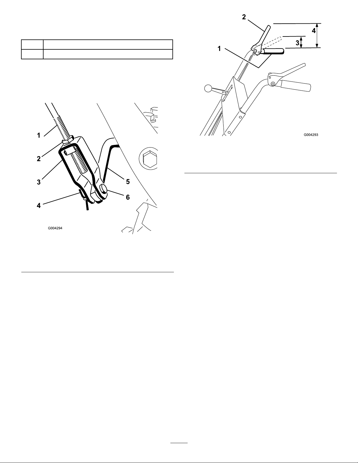
1.Loosenthejamnutabovetheclevisontheupper
controlrod(Figure8).
Figure9
1.Handgrip
2.Auger/impellercontrol
lever
3.1to2inches(2.5to5cm)
4.5inches(12.7cm)
Note:Thedistanceshouldbeapproximately5
inches(12.7cm).
Figure8
1.Uppercontrolrod
2.Jamnut5.Lowercontrolrod
3.Clevis6.Clevispin
4.Cotterpin
2.Aligntheholesintheclevisandthelowercontrol
rodandinserttheclevispin(Figure8).
3.Checkthedistancebetweenthetopofthehandgrip
andthebottomoftheauger/impellerdrivecontrol
lever(Figure9).
4.Presstheauger/impellerdrivecontrolleverslowly
towardthehandgrip.
Note:Theamountofforceneededtocompressthe
leverincreasesnoticeablywhenyouremovetheslack
fromtheauger/impellerdrivebelt(approximately
1/2ofthelevermovement).Theadjustmentis
correctwhentheforcebeginstoincreaseandthe
distancebetweenthetopofthehandgripandthe
bottomoftheauger/impellerdrivecontrolleveris1
to2inches(2.5to5cm)asshowninFigure9.
Note:Iftheforcedoesnotnoticeablyincrease,
removethebeltcover(refertostep2ofReplacing
theTractionDriveBelt)andmeasure2inches(5cm)
abovethehandgripatthepointwhereyouremove
theslackfromtheauger/impellerdrivebelt.
5.Toadjustthedistance:
A.Removetheclevispin.
B.Loosenthejamnut.
C.Threadtheclevisupordowntoincreaseor
decreasethedistancebetweenthetopofthe
handgripandthebottomoftheauger/impeller
drivecontrollever(Figure8).
6.Whentheadjustmentiscorrect,installtheclevispin
andsecureitinplacewiththecotterpin(Figure8).
7.Tightenthejamnuttosecuretheclevis(Figure8).
9
Page 10
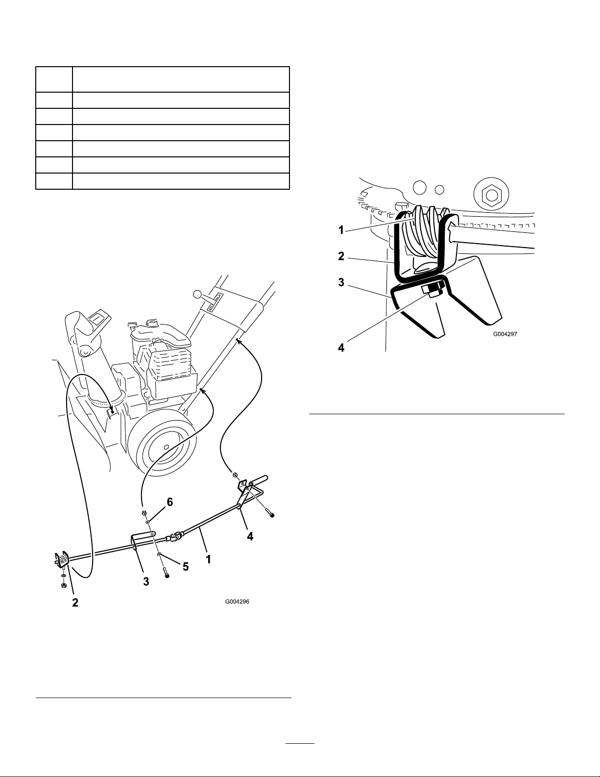
5.InstallingtheChuteControl
Rod
Chutecontrolrodassembly(rodandbracket,worm
1
gear,andbracket)
1Bellevillewasher
2Bolt
1
Carriagebolt
3Locknut
1
Curvedwasher
1Flatwasher
Procedure
1.Securetheupperchutecontrolbracket(attachedto
thechutecontrolrod)totheupperleftsideofthe
handlewithaboltandalocknut(Figure10).
2.Securethelowerchutecontrolbracket(attachedto
thechutecontrolrod)tothelowerleftsideofthe
handlewithabolt,acurvedwasher,aatwasher,
andalocknut(Figure10).
Note:Thebracketshouldbefastenedontheinside
ofthehandle,andtherodshouldbeapproximately
paralleltothegroundandnottouchthehandle.
Note:Leavethelocknutloose.
3.ApplyNo.2generalpurposegreasetotheworm
gear(Figure11).
Figure10
1.Chutecontrolrod
2.Wormgear,bracket,and
mountingange
3.Lowerchutecontrol
bracket
Note:Leavethelocknutloose.
4.Upperchutecontrol
bracket
5.Curvedwasher
6.Flatwasher
Figure11
1.Wormgear
2.Bracket4.Bolt,Bellevillewasher,
3.Mountingange
andlocknut
4.Looselymountthewormgearandthebrackettothe
mountingangewithabolt,aBellevillewasher,and
alocknutasshowninFigure11.
5.Slidethewormgearintotheteethofthechute
retainingringandtightenthelocknut(Figure11).
6.Tightenthelocknutsthatsecurethe2chutecontrol
brackets(Figure10).
7.Checktheoperationofthechutecontrolrod,and
movethewormgearslightlyoutwardifitbinds.
6.FillingtheEnginewithOil
Procedure
Yoursnowthrowercomeswith21oz.(0.62l)ofoilin
theengine.
Note:Beforestartingtheengine,checktheoillevel
andaddoilifnecessary.
Max.ll:21oz.(0.62l),type:automotivedetergent
oilwithanAPIserviceclassicationofSF,SG,SH,SJ,
SL,orhigher.
10
Page 11
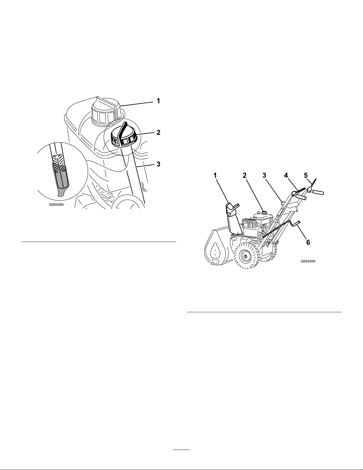
•Fortemperaturesabove32°F(0°C),useSAE30.
•Fortemperaturesbetween0°Fand32°F(-18°Cto
0°C),useSAE5W30orSAE10.
•Forairtemperaturesbelow0°F(-18°C),use
SAE0W30.
1.Movethesnowthrowertoalevelsurfacetoensure
anaccurateoillevelreading.
7.CheckingtheTirePressure
Procedure
Thetiresareoverinatedatthefactoryforshipping.
Reducethepressureequallyinbothtirestobetween12
and15psi(83and103kPa).
2.Cleanaroundthedipstick(Figure12).
Figure12
1.Fueltankcap3.Fillerhole
2.Dipstick
3.Removethedipstickbyrotatingthecap
counterclockwiseandpullingitout.
8.CheckingtheSkidsand
Scraper
Procedure
RefertoCheckingandAdjustingtheSkidsandScraper
inMaintenance.
ProductOverview
4.Slowlypourabout3/4ofthecrankcasecapacityof
oilintothecrankcase.
5.Wipethedipstickcleanwithacleancloth.
6.Installthedipstickintothellerneck,thenremoveit.
Note:Toensureanaccurateoillevelreading,you
mustfullyinstallthedipstick.
7.Readtheoillevelonthedipstick.
8.IftheoillevelisbelowtheAddmarkonthedipstick,
slowlypouronlyenoughoilintothellerholeto
raisetheoilleveltotheFullmarkonthedipstick.
Important:Donotoverllthecrankcasewith
oilandruntheengine;enginedamagewill
result.Draintheexcessoiluntiltheoillevelon
thedipstickreadsFull.
9.Insertthedipstickintothellerneckandrotatethe
capclockwiseuntilitistight.
1.Chutedeector
2.Fueltank
3.Speedselectorlever
Figure13
4.Tractioncontrollever
5.Auger/impellerdrive
controllever
6.Dischargechutecontrol
11
Page 12
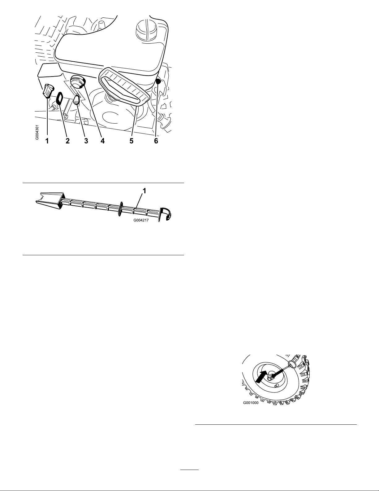
Figure14
1.Choke
2.Ignition5.Recoilstarter
3.Throttlelever6.Electricstarter
4.Primer
•ChuteDeectorHandle—Movethedeector
handleforwardtomovethesnowstreamdown;
moveitrearwardtomovethesnowstreamup.
•FuelShutoffV alve—Closethevalveby
rotatingclockwise.Openthevalvebyrotatingit
counterclockwise.Closethevalvewhenyoudonot
usethesnowthrower.
•Choke—Movethechoketothe(Full)positionto
startacoldengine.Asenginewarmsup,gradually
movethechoketotheOffposition.
•IgnitionSwitch—Insertthekeybeforestartingthe
engine.Tostoptheengine,removethekey .
•ThrottleLever—Movethethrottleleverupward
toincreasetheenginespeed;moveitdownwardto
decreasetheenginespeed.Movethethrottleleverto
theStoppositiontostoptheengine.
•Prime—Presstheprimertopumpasmallamountof
gasolineintotheengineforimprovedcold-weather
starting.
•RecoilStarter—Therecoilstarterisontheback
sideoftheengine.Pulltherecoilstartertostartthe
engine.
Figure15
1.Snowcleanoutstick(attachedtothetopoftheauger
housing)
Controls
•Auger/ImpellerDriveControlLever—T oengage
boththeaugerandimpeller,presstheleveragainst
therighthandgrip.Todisengage,releasethelever.
•TractionControlLever—Toengagethetraction
(wheeldrive),presstheleveragainsttheleft
handgrip.Tostopthetraction,releasethelever.
•SpeedSelectorLever—Thiscontrolhas4
positions:3forwardspeedsand1reverse.Tochange
speeds,movethespeedselectorlevertothedesired
position.Theleverlocksinanotchateachspeed
selection.
Note:Beforeshiftinggearsintooroutofreverse,
youmustreleasethetractioncontrollever.Youmay
shiftbetweenanyoftheforwardspeedswithout
releasingthetractioncontrollever.
Operation
Note:Determinetheleftandrightsidesofthemachine
fromthenormaloperatingposition.
FreewheelingorUsingthe
Self-propelDrive
Youcanoperatethesnowthrowerwiththeself-propel
featureengagedordisengaged(freewheeling).
Tofreewheel,slidethewheelsinwardandinserttheaxle
pinsthroughtheouteraxleholes,butnotthroughthe
wheelhubs(Figure16).
Figure16
•DischargeChuteControl—Rotatethedischarge
chutecontrolclockwisetomovethedischargechute
totheleft;counterclockwisetomovethechuteto
theright.
Toself-propel,slidethewheelsoutwardandinsertthe
axlepinsthroughtheholesinthewheelhubsandthe
outeraxleholes(Figure17).
12
Page 13
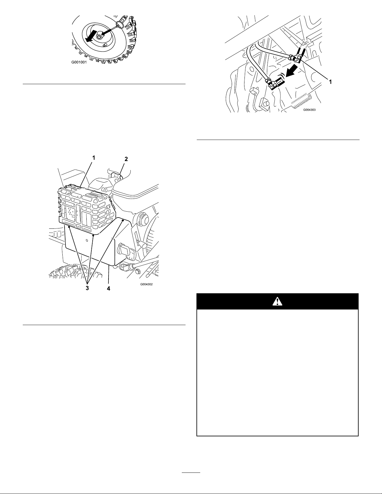
RemovingtheCarburetor
Figure17
HeaterBox
Ifyouoperatetheenginewhentheairtemperatureis
above40°F(4°C),removethecarburetorheaterbox
(Figure18).
Figure18
1.Muferguard3.Screws
2.Spark-plugwire4.Carburetorheaterbox
1.Disconnectthewirefromthesparkplugandensure
thatthewiredoesnotcontacttheplug(Figure18).
2.Removethekeyfromtheignitionswitch(Figure14).
3.Pullthechokeknoboff(Figure14).
4.Removethefastenersthatsecurethecarburetor
heaterboxinplace(Figure18).
Note:Installthesefastenersintheirholesforsafe
keeping.
5.Liftthecarburetorheaterboxupandawayfrom
theengine.
6.Disconnectthegreengroundwireclipunderthe
throttle(Figure19).
Figure19
1.Greengroundwireclip
7.Installthechokeknob.
8.Inserttheignitionkey.
9.Connectthewiretothesparkplug.
Important:Usethecarburetorheaterboxasa
referenceforthechokeandthrottlepositions.
InstallingtheCarburetor
HeaterBox
Toinstallthecarburetorheaterbox,reversethesteps
giveninRemovingtheCarburetorHeaterBox.Remove
thefastenersfromtheirholesbeforeinstallingthe
carburetorheaterbox.
FillingtheFuelTank
Gasolineisextremelyammableandexplosive.
Areorexplosionfromgasolinecanburnyou
andothers.
•Topreventastaticchargefromigniting
thegasoline,placethecontainerand/or
snowthroweronthegroundbeforelling,
notinavehicleoronanobject.
•Fillthetankoutdoorswhentheengineis
cold.Wipeupspills.
•Donothandlegasolinewhensmokingor
aroundanopenameorsparks.
•Storegasolineinanapprovedfuelcontainer,
outofthereachofchildren.
Fillthefueltankwithfreshunleadedregulargasoline
fromamajorname-brandservicestation.
13
Page 14
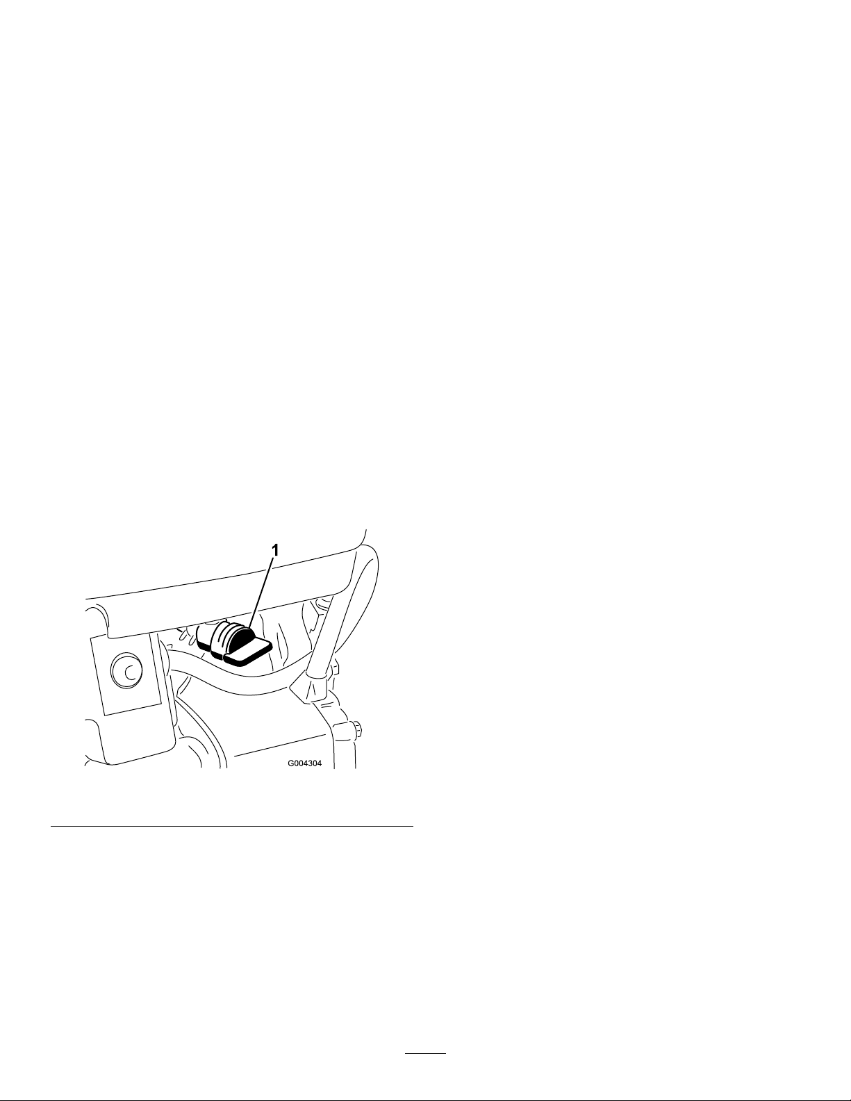
Important:Toreducestartingproblems,add
fuelstabilizertothefuelallseason,mixingitwith
gasolinelessthan30daysold.
Do not add oil to
the gasoline.
1.Cleanaroundthefueltankcap(Figure12).
2.Removethefueltankcap.
3.Fillthefueltankwithunleadedgasolinetowithin
1/4to1/2(6to13mm)fromthetopofthetank.
Donotllintothellerneck.
8.Grasptherecoilstarterhandle(Figure14)andpull
itoutslowlyuntilpositiveengagementresults;then
pullthehandlevigorouslytostarttheengine.
9.Keeparmgriponthestarterhandleandreturn
theropeslowly .
Note:Ifenginedoesnotstartoriftheair
temperatureis-10°F(-23°C)orbelow,theengine
mayneedadditionalpriming.Afterpushinginthe
primer,trytostarttheenginebeforeprimingagain.
Important:Donotllthefueltankmore
than1/4inch(6mm)fromthetopofthetank
becausethegasolinemusthaveroomtoexpand.
4.Installthefueltankcapandwipeupanyspilled
gasoline.
StartingtheEngine
1.Connectthesparkplugwire(Figure18).
2.MovethethrottlelevertotheFastposition
(Figure14).
3.Releasetheauger/impellerdrivecontrolleverand
thetractioncontrollever(Figure13).
4.Openthefuelshutoffvalvebelowthefueltank
(Figure20).
10.Aftertheenginestarts,immediatelyrotatethechoke
(Figure14)tothe3/4position.Astheenginewarms
up,rotatethechoketothe1/2position.Whenthe
enginewarmsupsufciently,rotatethechoketothe
Offposition.
11.Shiftthespeedselectorlever(Figure13)intorst
gear,squeezethetractioncontrollevertothe
handgrip,andthenreleasethetractioncontrollever.
Ifthesnowthrowermovesforwardbeforeengaging
thetractiondrivecontrolleverorafterreleasingthe
lever,seeAdjustingtheTractionDrive.
Important:Donotoperatethesnowthrower
iftheaugerandimpellerrotatewhenyou
disengagetheauger/impellerdrivecontrollever.
StoppingtheEngine
1.Engagetheaugertoclearanyremainingsnowfrom
insidethehousing.
2.Runtheengineforafewminutestodryoffany
accumulatedmoisture.
Figure20
1.Fuelshutoffvalve
5.Rotatethechoke(Figure14)totheOnposition.
6.Inserttheignitionkey(Figure14).
Important:Donotusetheprimerorthe
chokeiftheenginehasbeenrunningasishot.
Excessvieprimingmayoodtheengineand
preventitfromstarting.
7.Covertheholeinthecenteroftheprimer(Figure14)
withyourthumbandslowlypushintheprimer3
times,pausingamomentbetweenpushes.
3.Releasetheauger/impellerdrivecontrolleverand
thetractioncontrollever(Figure13).
4.Stoptheenginebydoingoneofthefollowing:
A.MovethethrottlelevertotheSlowposition,and
removetheignitionkey.
B.MovethethrottlelevertotheStopposition.
5.Closethefuelshutoffvalve(Figure20).
6.Pulltherecoilstarterwitharapid,continuous,
full-armstroke3or4times.Thishelpspreventthe
recoilstarterfromfreezingup.
7.Waitforallmovingpartstostopbeforeleavingthe
operatingposition.
14
Page 15

UncloggingtheDischarge
Chute
Iftheauger/impellerisrunningbutthereisnosnow
comingoutofthedischargechute,thedischargechute
maybeclogged.
•Tounclogthedischargechute,stayintheoperating
positionandreleasethelefthand(traction)lever.
Whilerunningtheauger/impeller,pushdownonthe
handlestoraisethefrontofthesnowthrowerafew
inches(cm)offthepavement.Thenliftthehandles
quicklytobumpthefrontofthesnowthroweron
thepavement.Repeatifnecessaryuntilastreamof
snowcomesoutthedischargechute.
OperatingTips
Whenthesnowthrowerisinoperation,the
impellerandaugercanrotateandcutoffor
injurehandsandfeet.
•Beforeadjusting,cleaning,inspecting,
troubleshooting,orrepairingthe
snowthrower,stoptheengineandwaitfor
allmovingpartstostop.Disconnectthe
wirefromthesparkplugandkeepitaway
fromtheplugtopreventsomeonefrom
accidentallystartingtheengine.
•Ifyoucannotunclogthedischargechutebybumping
thefrontofthesnowthrower,stoptheengine,wait
forallmovingpartstostop,andusethecleanout
tool;neveruseyourhand.
Important:Uncloggingthedischargechuteby
bumpingthefrontofthesnowthroweronthe
pavementmaycausetheskidstomove.Adjust
theskidsandtightentheskidboltssecurely.
PreventingFreeze-up
•Insnowyandcoldconditions,somecontrolsand
movingpartsmayfreeze.Donotuseexcessive
forcewhentryingtooperatefrozencontrols.If
youhavedifcultyoperatinganycontrolorpart,
starttheengineandletitrunforafewminutes.
•Afterusingthesnowthrower,lettheenginerunfora
fewminutestopreventmovingpartsfromfreezing.
Engagetheauger/impellertoclearanyremaining
snowfrominsidethehousing.Rotatethedischarge
chutecontroltopreventitfromfreezing.Stopthe
engine,waitforallmovingpartstostop,andremove
alliceandsnowfromthesnowthrower.
•Withtheengineoff,pulltherecoilstarterhandle
severaltimestopreventtherecoilstarterfrom
freezingup.
•Removeanobstructionfromthedischarge
chute;refertoUncloggingtheDischarge
Chute.Ifnecessary,useastick,notyour
hands,toremoveanobstructionfromthe
dischargechute.
•Staybehindthehandlesandawayfrom
thedischargeopeningwhileoperatingthe
snowthrower.
•Keepface,hands,feet,andanyotherpartof
yourbodyorclothingawayfromconcealed,
moving,orrotatingparts.
Therotorbladescanthrowstones,toys,and
otherforeignobjectsandcauseseriouspersonal
injurytotheoperatorortobystanders.
•Keeptheareatobeclearedfreeofallobjects
thattherotorbladescouldpickupand
throw.
•Keepallchildrenandpetsawayfromthe
areaofoperation.
•AlwayssetthethrottlelevertotheFastposition
whenthrowingsnow.
•Iftheengineslowsdownunderaloadorthewheels
slip,shiftthesnowthrowerintoalowergear.
•Ifthefrontofthesnowthrowerridesup,shiftthe
snowthrowerintoalowergear.Ifthefrontcontinues
torideup,liftuponthehandles.
15
Page 16

Maintenance
Note:Determinetheleftandrightsidesofthemachinefromthenormaloperatingposition.
RecommendedMaintenanceSchedule(s)
MaintenanceService
Interval
Afterthersthour
Aftertherst2hours
Beforeeachuseordaily
Every20hours
Every25hours
Every100hours
Yearly
Yearlyorbeforestorage
MaintenanceProcedure
•Inspectandadjustthetractiondrivebelt.
•Inspectandadjusttheauger/impellerdrivebelt.
•Changetheengineoil.
•Checktheengineoillevelandaddoilifnecessary .
•Inspectandadjustorreplacethetractiondrivebeltwhennecessary.
•Inspectandadjustorreplacetheauger/impellerdrivebeltwhennecessary.
•Lubricatethesnowthrower.
•Changetheengineoil.
•Inspectthesparkplug.Replaceand/orgapitifnecessary.
•Checktheskidsandthescraperandadjustthemifnecessary.
•Checktheaugergearboxoilandaddoilifnecessary.
•Changetheengineoil.
•Lubricatethesnowthrower.
•Drainthegasolineandruntheenginetodryoutthefueltankandthecarburetorat
theendoftheseason.
Important:Refertoyourengineoperator’smanualforadditionalmaintenanceprocedures.Forengine
adjustments,repairs,orwarrantyservicenotcoveredinthismanual,contactanAuthorizedTecumseh
ServicingDealer.
Ifyouleavethewireonthesparkplug,someonecouldaccidentlystarttheengineandseriouslyinjure
youorbystanders.
Disconnectthewirefromthesparkplugbeforeyoudoanymaintenance.Setthewireasidesothat
itdoesnotaccidentallycontactthesparkplug.
PreparingforMaintenance
1.Movethesnowthrowertoalevelsurface.
2.Stoptheengineandwaitforallmovingpartstostop.
3.Disconnectthesparkplugwire(Figure18).
CheckingtheEngineOilLevel
ServiceInterval:Beforeeachuseordaily
Eachtimebeforeusingthesnowthrower,rstensure
thattheoillevelisbetweentheAddandtheFullmarks
onthedipstick.
1.Cleanaroundthedipstick(Figure18).
2.Removethedipstickbyrotatingthecap
counterclockwiseandpullingitout.
3.Wipethedipstickcleanwithacleancloth.
4.Installthedipstickintothellerneck,thenremoveit.
Note:Toensureanaccurateoillevelreading,you
mustfullyinstallthedipstick.
16
Page 17
5.Readtheoillevelonthedipstick.
6.IftheoillevelisbelowtheAddmarkonthedipstick,
slowlypouronlyenoughoilintothellerholeto
raisetheoilleveltotheFullmarkonthedipstick.
Note:Useonlyahigh-quality ,SAE5W-30or
SAE10weightdetergentoilthathastheAmerican
PetroleumInstitute(API)serviceclassicationSF,
SG,SH,orSJ.Forextremelycoldconditions(below
0°For-18°C),use0W -30weightdetergentoilthat
hastheAmericanPetroleumInstitute(API)service
classicationSF,SG,SH,orSJ .
Important:Donotoverllthecrankcasewith
oilandruntheengine;enginedamagewill
result.Draintheexcessoiluntiltheoillevelon
thedipstickreadsFull.
7.Insertthedipstickintothellerneckandrotatethe
capclockwiseuntilitistight.
AdjustingtheSkidsand
Figure22
1.Augerblade
2.Scraper
3.Mountingscrew(5)
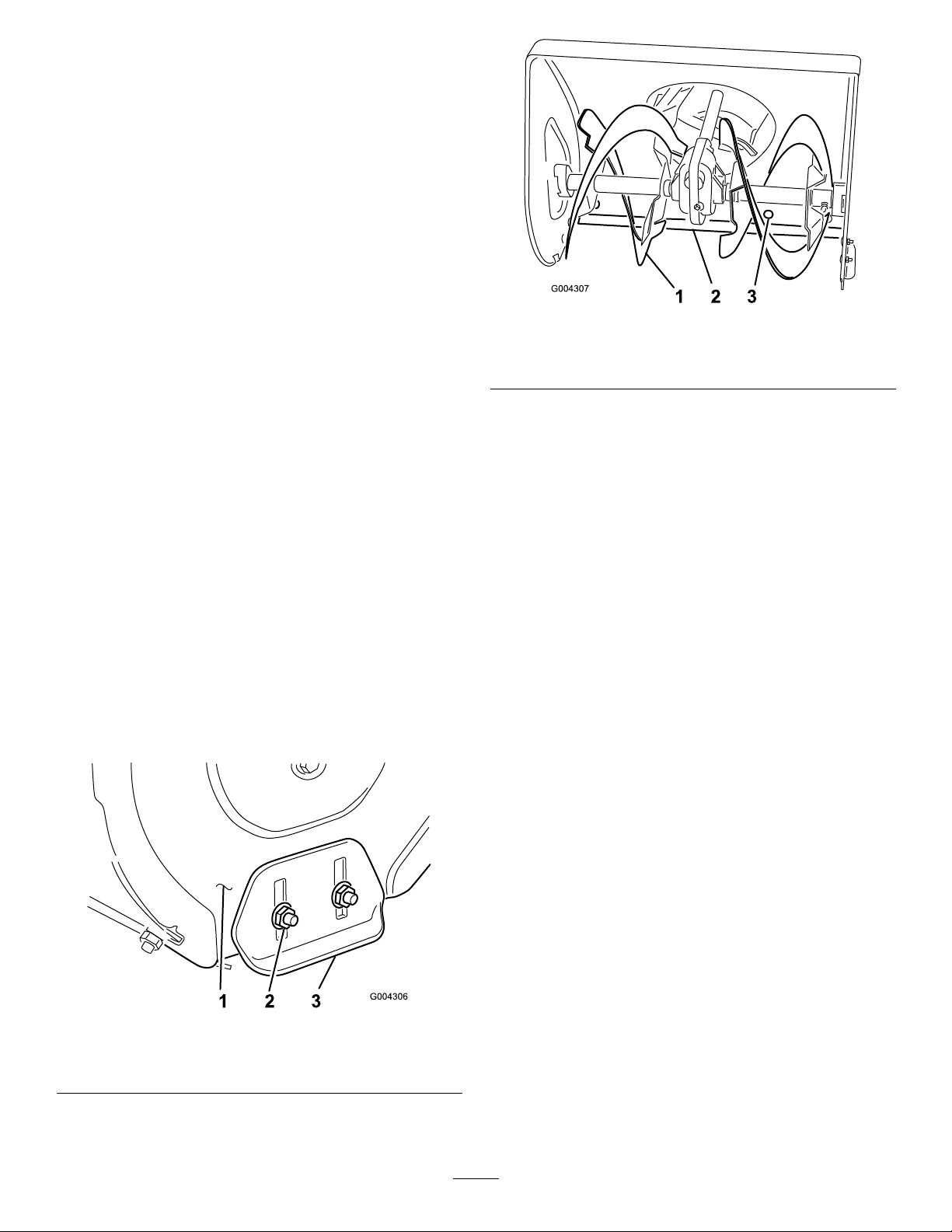
5.Checkthescraperadjustment.Thescrapershouldbe
1/8inch(3mm)aboveandparalleltoalevelsurface.
A.ForConcreteandAsphaltSurfaces:
Scraper
ServiceInterval:Yearly
Adjusttheskidsandthescraperinitiallyandthenas
neededtoensurethattheaugerdoesnotcontactthe
pavedorgravelsurface.Also,adjustthemasneededto
compensateforwear.
1.Movethesnowthrowertoalevelsurface.
2.Checkthetirepressureinthetires.RefertoChecking
theTirePressure.
3.Loosenthe4angenutsthatsecurebothskidsto
theaugersideplates(Figure21)untiltheskidsslide
upanddowneasily.
Figure21
1.Augersideplate(2)3.Skid(2)
2.Flangenuts(4)
4.Supporttheaugerbladessothattheyare1/8inch(3
mm)offtheground(Figure22).
Ifthesnowthrowerdoesnotclearthesnowclose
enoughtothepavement,adjusttheskidsto
lowerthescraper;ifthepavementsurfacesare
cracked,rough,oruneven,adjusttheskidsto
raisethescraper.
B.ForGravelSurfaces:
Supporttheaugerbladesafewinches(cm)above
theground,andadjusttheskidstopreventthe
snowthrowerfrompickinguprocks.
6.Toadjustthescraper,loosenthe5mounting
screws(Figure22),levelthescraper,andtightenthe
mountingscrews.
7.Movetheskidsdownasfaraspossible.
8.Tightenthe4angenutsthatsecurebothskidsto
theaugersideplates(Figure21).
9.Connectthewiretothesparkplug.
AdjustingtheSpeedSelector
Adjustthespeedselectorlinkageinitiallyandwhenthe
snowthrowerisslow,rstgearhasnospeed,orthe
speedselectorleverdoesnotmoveintothirdgear.
1.Draingasolinefromthefueltankandtheoilfrom
thecrankcase.RefertoEmptyingtheFuelTankand
toChangingtheEngineOil.
2.Tipthesnowthrowerforwardandblockitsothatit
cannotfall.
3.Removethe4ange-headboltsthatsecurethe
bottomcovertotheframeandremovethecover
(Figure27).
17
Page 18
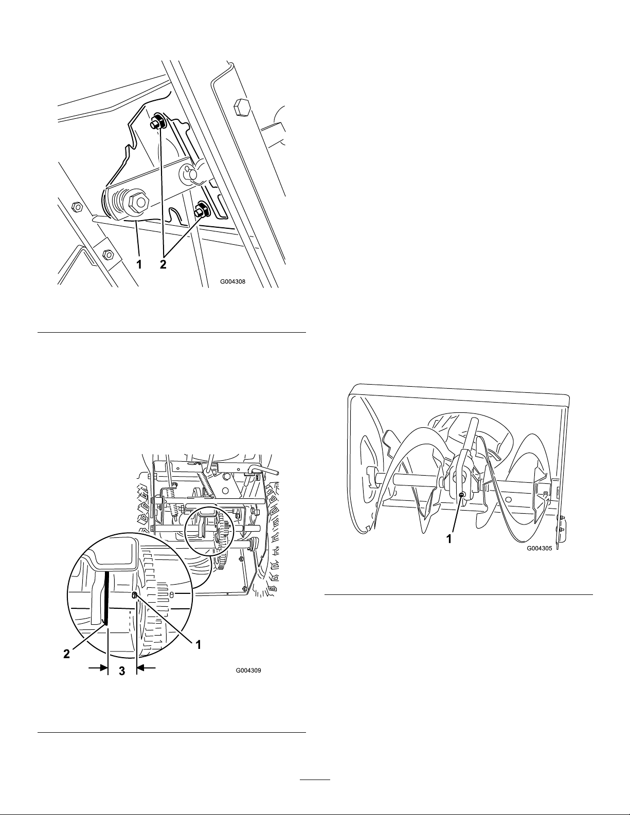
4.Loosentheangenutsthatsecuretheselectorplate
tothecontrolpanel(Figure23).
Figure23
1.Speedselectorplate
2.Flangenuts
5.Shiftthespeedselectorlevertothirdgearandpush
downonthespeedselectorplatetomovethedrive
assemblytotheright.
6.Withthedriveassembly1/8inch(3mm)fromthe
rollpin,tightentheangenutsthatsecurethespeed
selectorplate.
7.ShiftthespeedselectorlevertotheR(Reverse)
positionandbacktothirdgeartocheckthe
adjustment.
8.Ifthespacebetweentherollpinandthedrive
assemblyismorethan3/16inch(5mm),repeat
steps3through6.
9.Installthebottomcoverandreturnthesnowthrower
totheuprightposition.
10.Connectthewiretothesparkplug.
CheckingtheAugerGearbox
Grease
ServiceInterval:Yearly
Theaugergearboxispackedwith5oz.(140g)of
LubriplateMAG-1(alow-temperature,high-pressure
grease)andissealedatthefactory.Thepipeplug
(Figure25)isforfactoryuseonly;youdonotneedto
checkoraddgrease.Ifthegearboxisleakinggrease,
contactanAuthorizedServiceDealer.
Note:Thedriveassemblyshouldbe1/8inch(3
mm)fromtherollpin;ifnot,slidetheselectorplate
(Figure23)untilthegapis1/8inch(3mm);refer
toFigure24.
Figure24
1.Rollpin
2.Driveassembly
3.1/8inch(3mm)
Figure25
1.Pipeplug
ChangingtheEngineOil
ServiceInterval:Aftertherst2hours
Yearly
Every25hours
Changetheengineoilaftertherst2operatinghours,
thenyearlythereafter.Ifpossible,runtheenginejust
beforechangingtheoilbecausewarmoilowsbetter
andcarriesmorecontaminants.
18
Page 19
Max.ll:21oz.(0.62l),type:automotivedetergent
oilwithanAPIserviceclassicationofSF,SG,SH,SJ,
SL,orhigher.
LubricatingtheSnowthrower
ServiceInterval:Every20hours
•Fortemperaturesabove32°F(0°C),useSAE30.
•Fortemperaturesbetween0°Fand32°F(-18°Cto
0°C),useSAE5W30orSAE10.
•Forairtemperaturesbelow0°F(-18°C),use
SAE0W30.
1.Blockuptherearofthesnowthrower.
2.Removetheleftwheel.
3.Cleantheareaaroundtheoildrainplug(Figure26).
Yearlyorbeforestorage
Lightlylubricateallmovingpartsofthesnowthrower
afterevery20operatinghoursandattheendofthe
snowthrowingseason.
Important:Donotgetoilorgreaseontherubber
wheelorfrictiondriveplatebecausethewheelwill
slipandtherubbermaydeteriorate.
1.Draingasolinefromthefueltankandtheoilfrom
thecrankcase.RefertoEmptyingtheFuelTankand
toChangingtheEngineOil.
2.Tipthesnowthrowerforwardontothe
auger/impellerhousingandblockitsothatitcannot
fall.
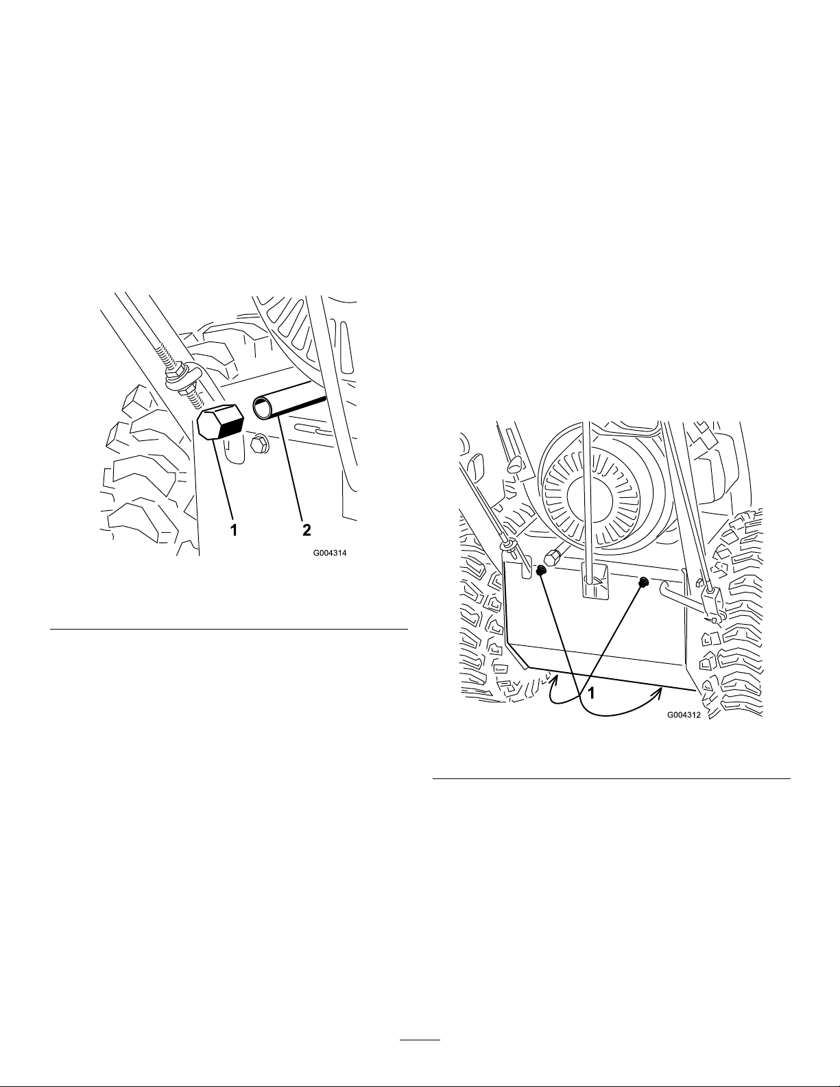
3.Removethe4ange-headboltsthatsecurethe
bottomcoverandremovethecover(Figure27).
Figure26
1.Oildrainplug
2.Drainextension
4.Slideanoildrainpanunderthedrainextensionand
removetheoildrainplug(Figure26).
Note:Placeafunnelunderthedrainextensionso
theoildrainsdirectlyintotheoildrainpanandaway
fromthesnowthrower.
5.Draintheoil.
Note:Disposeoftheusedoilproperlyatalocal
recyclingcenter.
6.Installtheoildrainplug.
7.Installtheleftwheel.
8.Fillthecrankcasewithoil.RefertoFillingthe
EngineCrankcasewithOil.
9.Wipeupanyspilledoil.
Figure27
1.Flange-headbolts
4.Lightlylubricatethesnowthrowerwithlightoilas
showninFigure28.
19
Page 20
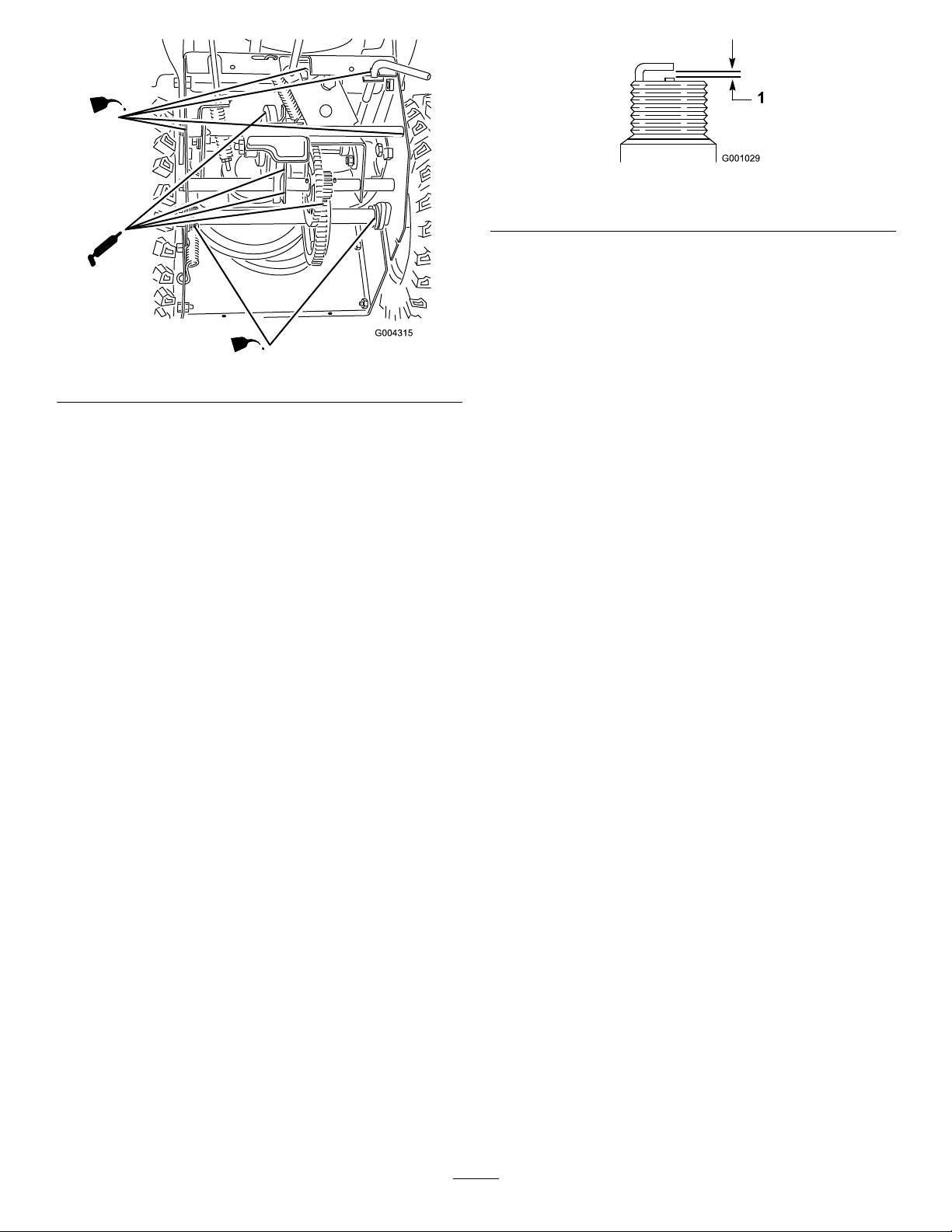
Figure28
Figure29
1.0.030inch(0.76mm)
5.Installthesparkplugbyhandandthentorqueitto
15ft-lb(20.4N-m).
Note:Ifyoudonothaveatorquewrench,tighten
theplugrmly.
AdjustingtheTractionDrive
Important:Donotexcessivelyoilthe
snowthrower;extraoilmayenterthetraction
driveandcausethetractiondrivebelttoslip.
5.Wipeupanyexcessoil.
6.GreasethesnowthrowerasshowninFigure28.
7.Wipeupanyexcessgrease.
8.Installthebottomcover.
9.Returnthesnowthrowertoitsuprightposition.
10.Connectthewiretothesparkplug.
InspectingandReplacingthe
SparkPlug
ServiceInterval:Every100hours
UseaChampionRN4Corequivalentsparkplug.
Checkandgapthesparkyearly,andreplacetheplug
ifnecessary.
1.Cleanaroundthebaseofthesparkplug.
2.Removethesparkplug.
3.Examinethesparkplugandreplaceitifitiscracked,
fouled,dirty,oriftheelectrodesareworn.
Important:Donotcleantheelectrodesbecause
gritcouldenterthecylinderanddamagethe
engine.
Belt
ServiceInterval:Afterthersthour
Beforeeachuseordaily
Adjustthetractiondrivebeltaftertherstoperating
hour,afterevery5operatinghoursthereafter,and
whenthespeedselectorlevershiftsproperlybutthe
snowthrowerdoesnotdriveintheforwardorreverse
speeds.
1.Checkandadjustthetractiondriveasdescribedin
InstallingtheTractionRod.
2.Iftheproblempersistsafteradjustingthelinkage,
contactanAuthorizedServiceDealer.
3.Connectthewiretothesparkplug.
ReplacingtheTractionDrive
Belt
Ifthetractiondrivebeltbecomesworn,oil-soaked,or
otherwisedamaged,replacethebelt.
1.Draingasolinefromthefueltankandtheoilfrom
thecrankcase.RefertoEmptyingtheFuelTankand
toChangingtheEngineOil.
2.Removethe2ange-headboltsthatholdthebelt
coverinplaceandsetthecoveraside(Figure30).
4.Setthegapbetweentheelectrodesonthesparkplug
at0.030inch(0.76mm)(Figure29).
20
Page 21
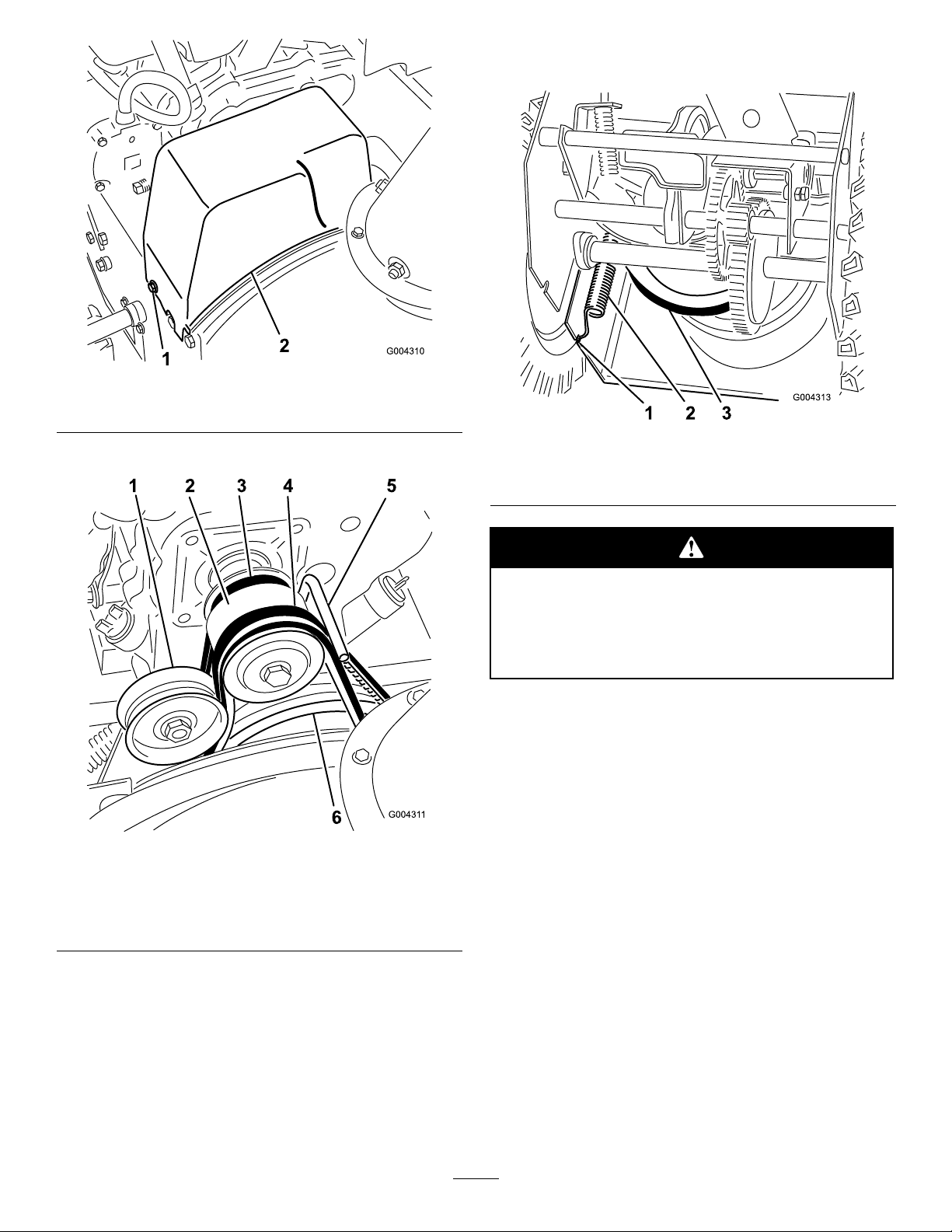
Figure30
1.Flange-headbolt(2)
2.Beltcover
3.Loosenthebeltguide(Figure31).
7.Disconnectthespringfromthenotchinthebottom
edgeofthesideplate(Figure32).
Figure32
1.Notchinsideplate3.Largetractionpulley
2.Spring
Figure31
1.Idlerpulley
2.Enginepulley5.Beltguide
3.Tractiondrivebelt
4.Auger/impellerdrivebelt
6.Largeauger/impeller
pulley
4.Removetheauger/impellerdrivebeltfromthe
enginepulleyandthelargeauger/impellerpulley
(Figure31).
5.Tipthesnowthrowerforwardandblockitsothatit
cannotfall.
6.Removethe4ange-headboltsthatsecurethe
bottomcovertotheframeandremovethecover
(Figure27).
Thespringisunderheavytensionandcould
injuretheyouorabystanderifyoudonot
carefullyremoveit.
Carefullyremovethespring.
8.Setthesnowthrowerupright.
9.Removethetractiondrivebeltfromtheengine
pulleyandthelargetractionpulley(Figure31).
10.Installanewbeltaroundthelargetractionpulley.
11.Loopthebeltovertheenginepulley,ensuringthat
thebeltisontheinsideofthebeltguide(Figure31).
12.Tipthesnowthrowerforwardandblockitsothatit
cannotfall.
13.Hookthespringintothenotchinthebottomedge
ofthesideplate(Figure32).
14.Replacethebottomcoverwiththe4ange-head
bolts.
15.Setthesnowthrowerupright.
16.Installtheauger/impellerdrivebeltaroundthelarge
auger/impellerpulleyandenginepulley,ensuring
thatthebeltisontheinsideoftheidlerpulleyand
thebeltguide(Figure31).
17.Adjustthebeltguidesothatthereis1/8inch(3mm)
ofclearancebetweentheauger/impellerdrivebelt
21
Page 22

andtheguide,andsecurethebeltguidewhenthe
auger/impellerdrivebeltistight.
18.Checktheauger/impellerdrivelinkageandadjustit
ifnecessary.Refertosteps4through7ofInstalling
theAuger/ImpellerDriveControlLinkage.
19.Installthebeltcover.
20.Connectthewiretothesparkplug.
AdjustingtheAuger/Impeller
DriveBelt
ServiceInterval:Afterthersthour
Beforeeachuseordaily
Operatingthesnowthrowerwithanauger/impellerdrive
beltthatslipsdecreasesthesnowthrowingperformance
anddamagesthebelt.Checktheauger/impellerdrive
beltforthepropertensionaftertherstoperatinghour,
thenadjustthebeltwhennecessary.
Improperlyadjustingtheauger/impellermay
causeittoturnwhendisengaged.Arotating
augerorimpellercancutofforinjurengers,
hands,orfeet.
•Keepyourface,hands,feet,andanyother
partofyourbodyorclothingawayfrom
concealed,moving,orrotatingparts.
•Ensurethattheimpellerbrakearmclearance
ismaintained.
ReplacingtheAuger/Impeller
DriveBelt
Iftheauger/impellerdrivebeltbecomesworn,
oil-soaked,orotherwisedamaged,replacethebelt.
1.Removethe2ange-headboltsthatholdthebelt
coverinplaceandsetthecoveraside(Figure30).
2.Loosenthebeltguide(Figure31).
3.Removetheauger/impellerdrivebeltfromthe
enginepulleyandthelargeauger/impellerpulley
(Figure31).
4.Installanewbeltaroundthelargeauger/impeller
pulley(Figure31).
5.Loopthebeltovertheenginepulley,ensuringthat
thebeltisontheinsideoftheidlerpulleyandthe
beltguide(Figure31).
6.Adjustthebeltguidesothatthereis1/8inch(3mm)
ofclearancebetweentheauger/impellerdrivebelt
andtheguide,andsecurethebeltguide.
7.Checkandadjusttheauger/impellerdrivebeltas
instructedinInstallingtheAuger/ImpellerDrive
ControlLinkage.
8.Installthebeltcover.
9.Connectthewiretothesparkplug.
Important:Donotoperatethesnowthrower
iftheaugerandtheimpellerrotatewhenyou
disengagetheauger/impellerdrivecontrollever.
EmptyingtheFuelTank
1.Closethefuelshutoffvalve(Figure20).
•Donotadjusttheauger/impellerdrive
belttootightbecauseitmaycausethe
auger/impellertoturnwhenthecontrol
leverisintheDisengagedposition.Ifthis
occurs,decreasethebelttension.
1.CheckandadjustthebeltasinstructedinInstalling
theAuger/ImpellerDriveControlLinkage.
2.Connectthewiretothesparkplug.
3.Checkthebelttensionbyoperatingtheauger.
4.Ifthebeltstillslips,replaceit.RefertoReplacingthe
Auger/ImpellerDriveBelt.
Important:Donotoperatethesnowthrower
iftheaugerandtheimpellerrotatewhenyou
disengagetheauger/impellerdrivecontrollever.
Gasolineishighlyammable;itcanigniteand
causeseriouspersonalinjury.
•Draingasolineoutdoors
•Draingasolinefromacoldengineonly.
•Wipeupanygasolinethatmayhavespilled.
•Donotdraingasolinenearanyopename
orwheregasolinefumesmaybeignitedby
aspark.
•Donotsmokeacigar,acigarette,orapipe
whenhandlinggasoline.
2.Placeacleandrainpanunderthefuelshutoffvalve.
3.Loosenthehoseclampthatsecuresthefuellineto
thevalveandslidethefuellineoffthefuelshutoff
valve(Figure20).
22
Page 23

4.Openthefuelshutoffvalveandallowthefuelto
drainoutofthefueltankintothedrainpan.
11.Pulltherecoilstarterslowlytodistributetheoilon
theinsideofthecylinder.
5.Installthefuellineontothefuelshutoffvalveand
secureitwithahoseclamp.
6.Connectthewiretothesparkplug.
7.Startthesnowthrowerandruntheengineuntilit
stops.Repeatthisstep2moretimestoensurethat
thefueltankandthecarburetorareempty.
Storage
•Gasolinevaporscanexplode.
•Donotstoregasolinemorethan30days.
•Donotstorethesnowthrowerinan
enclosurenearanopename.
•Allowtheenginetocoolbeforestoringit.
PreparingtheSnowthrower
forStorage
1.Onthelastrefuelingoftheyear,addfuelstabilizer
tofreshfuelasdirectedbytheenginemanufacturer.
2.Runtheenginefor10minutestodistributethe
conditionedfuelthroughthefuelsystem.
12.Lubricatethesnowthrower.RefertoLubricatingthe
Snowthrower.
13.Cleanthesnowthrower.
14.Touchupchippedsurfaceswithpaintavailable
fromanAuthorizedServiceDealer.Sandaffected
areasbeforepainting,andusearustpreventativeto
preventthemetalpartsfromrusting.
15.Tightenanyloosefasteners.Repairorreplaceany
damagedparts.
16.Coverthesnowthrowerandstoreitinaclean,dry
placeoutofthereachofchildren.Allowtheengine
tocoolbeforestoringitinanyenclosure.
RemovingtheSnowthrower
fromStorage
1.Removethesparkplugandspintheenginerapidly
usingthestartertoblowtheexcessoilfromthe
cylinder.
2.Installthesparkplugbyhandandthentorqueitto
15ft-lb(20.4N-m).
3.Connectthesparkplugwire.
4.Performtheannualmaintenanceproceduresasgiven
intheRecommendedMaintenanceSchedule.
3.Stoptheengine,allowittocool,anddrainthe
fueltankorruntheengineuntilitstops.Referto
EmptyingtheFuelTank.
4.Starttheengineandrunituntilitstops.
5.Chokeorprimetheengine,startitathirdtime,and
runtheengineuntilitwillnotstart.
6.Disposeofunusedfuelproperly .Recycleitaccording
tolocalcodes,oruseitinyourautomobile.
Note:Donotstorestabilizedgasolineformore
than90days.
7.Whiletheengineisstillwarm,changetheengineoil.
RefertoChangingtheEngineOil.
8.Removethesparkplug.
9.Squirt2teaspoonsofoilintothesparkplughole.
10.Installthesparkplugbyhandandthentorqueitto
15ft-lb(20.4N-m).Ifyoudonothaveatorque
wrench,tightentheplugrmly.Donotconnect
thewiretotheplug.
23
Page 24

Troubleshooting
Problem
Electricstarterdoesnotturn(electric-start
modelsonly)
Enginedoesnotstartorstartshard
PossibleCauseCorrectiveAction
1.Thepowercordisdisconnectedatthe
outletorthesnowthrower.
2.Thepowercordisworn,corroded,or
damaged.
3.Thepoweroutletisnotenergized.
1.Thekeyisnotintheignitionorisinthe
Stopposition.
2.ThechokeisintheOffpositionandthe
primerhasnotbeenpressed.
3.Thefuelshutoffvalveisnotopen.3.Openthefuelshutoffvalve.
4.ThethrottleisnotintheFastposition.4.MovethethrottletotheFastposition.
5.Thefueltankisemptyorthefuel
systemcontainsstalefuel.
6.Thesparkplugwireislooseor
disconnected.
7.Thesparkplugispitted,fouled,orthe
gapisincorrect.
8.Thefuelventcapisrestricted.
9.Theengineoillevelintheengine
crankcaseistoolowortoohigh.
1.Connectthepowercordtotheoutlet
and/orthesnowthrower.
2.Replacethepowercord.
3.Haveaqualiedelectricianenergize
theoutlet.
1.Insertthekeyintotheignitionandturn
ittotheOnposition.
2.MovethechoketotheOnpositionand
presstheprimer3times.
5.Drainand/orllthefueltankwithfresh
gasoline(notmorethan30daysold).
Iftheproblempersists,contactan
AuthorizedServiceDealer.
6.Connectthewiretothesparkplug.
7.Checkthesparkplugandadjustthe
gapifnecessary .Replacethespark
plugifitispitted,fouled,orcracked.
8.Removetheventrestrictionorreplace
thefuelcap.
9.Addordrainoiltoadjusttheoillevelin
theenginecrankcasetotheFullmark
onthedipstick.
Enginerunsrough
Engineruns,butthesnowthrower
dischargessnowpoorlyornotatall
1.ThechokeisintheOnposition.1.MovethechoketotheOffposition.
2.Thefuelshutoffvalveisnotcompletely
open.
3.Thefueltankisnearlyemptyor
containsstalefuel.
4.Thesparkplugwireisloose.
5.Thesparkplugispitted,fouled,orthe
gapisincorrect.
6.Theengineoillevelintheengine
crankcaseistoolowortoohigh.
1.ThethrottleisnotintheFastposition
whenthrowingsnow .
2.Thesnowthrowerismovingtoofastto
clearthesnow.
3.Y ouaretryingtoremovetoomuch
snowperswath.
4.Y ouaretryingtoremoveextremely
heavyorwetsnow.
5.Thedischargechuteisplugged.5.Unclogthedischargechute.
6.Theauger/impellerdrivebeltisloose
orisoffthepulley .
2.Openthefuelshutoffvalve.
3.Drainandllthefueltankwithfresh
gasoline(notmorethan30daysold).
Iftheproblempersists,contactan
AuthorizedServiceDealer.
4.Connectthewiretothesparkplug.
5.Checkthesparkplugandadjustthe
gapifnecessary .Replacethespark
plugifitispitted,fouled,orcracked.
6.Addordrainoiltoadjusttheoillevelin
theenginecrankcasetotheFullmark
onthedipstick.
1.MovethethrottletotheFastposition.
2.Shiftthesnowthrowerintoalowergear .
3.Reducetheamountofsnowremoved
perswath.
4.Don’toverloadthesnowthrowerwith
extremelyheavyorwetsnow.
6.Installand/oradjusttheauger/impeller
drivebelt;refertowww.Toro.com
forservicinginformationortakethe
snowthrowertoanAuthorizedService
Dealer.
24
Page 25

Problem
7.Theauger/impellerdrivebeltisworn
orbroken.
PossibleCauseCorrectiveAction
7.Replacetheauger/impellerdrivebelt;
refertowww.Toro.comforservicing
informationortakethesnowthrowerto
anAuthorizedServiceDealer.
Dischargechuteeitherdoesnotlockinto
placeordoesnotmove
snowoffthesurface
1.Thedischargechutelatchisnot
properlyadjusted.
1.Theskidsand/orscraperarenot
properlyadjusted.
2.Thepressureinthetiresisnotequal.
1.Adjustthedischargechutelatch.
1.Adjusttheskidsand/orthescraper. Snowthrowerdoesnotproperlyclearthe
2.Checkandadjustthepressureinone
orbothtires.
25
Page 26

Notes:
26
Page 27

International Distributor List
Distributor: Country: Phone Number:
Atlantis Su ve Sulama Sisstemleri Lt Turkey 90 216 344 86 74
Balama Prima Engineering Equip Hong Kong 852 2155 2163
B-Ray Corporation Korea 82 32 551 2076
Casco Sales Company Puerto Rico 787 788 8383
Ceres S.A Costa Rica 506 239 1138
CSSC Turf Equipment (pvt) Ltd Sri Lanka 94 11 2746100
Cyril Johnston & Co Northern Ireland 44 2890 813 121
Equiver Mexico 52 55 539 95444
Femco S.A. Guatemala 502 442 3277
G.Y.K. Company ltd. Japan 81 726 325 861
Geomechaniki of Athens Greece 30 10 935 0054
Guandong Golden Star China 86 20 876 51338
Hako Gorund and Garden Sweden 46 35 10 0000
Hayter Limited (U.K.) United Kingdom 44 1279 723 444
Hydroturf Int. Co Dubai United Arab Emirates 97 14 347 9479
Hydroturf Egypt LLC Egypt 202 519 4308
Ibea S.p.A. Italy 39 0331 853611
Irriamc Portugal 351 21 238 8260
Jean Heybroek b.v. Netherlands 31 30 639 4611
Lely (U.K.) Limited United Kingdom 44 1480 226 800
Maquiver S.A. Colombia 57 1 236 4079
Maruyama Mfg. Co. Inc. Japan 81 3 3252 2285
Metra Kft Hungary 36 1 326 3880
Mountfield a.s. Czech Republic 420 255 704 220
Munditol S.A. Argentina 54 11 4 821 9999
Oslinger Turf Equipment SA Ecuador 593 4 239 6970
Oy Hako Ground and Garden Ab Finland 358 987 00733
Parkland Products Ltd New Zealand 64 3 34 93760
Prochaska & Cie Austria 43 1 278 5100
RT Cohen 2004 Ltd Israel 972 986 17979
Riversa Spain 34 9 52 83 7500
Roth Motorgerate GmBh & Co Germany 49 7144 2050
Sc Svend Carlsen A/S Denmark 45 66 109 200
Solvert S.A.S France 33 1 30 81 77 00
Spypros Stavrinides Limited Cyprus 357 22 434131
Surge Systems India Limited India 91 1 292299901
T-Markt Logistics Ltd Hungary 36 26 525 500
Toro Australia Australia 61 3 9580 7355
Toro Europe BVBA Belgium 32 14 562 960
374-0102 Rev B
Page 28

The Toro Warranty
Conditions and Products Covered
The Toro® Company and its afliate, Toro Warranty Company, pursuant to
an agreement between them, jointly promises to the original purchaser* to
repair any Toro Product used for normal residential purposes* if defective in
materials or workmanship. The following time periods apply from the date
of original purchase:
Products
Walk Power Mowers
Rear Engine Riders 2-year limited warranty
Lawn & Garden Tractors
Electric Hand Held Products
Snowthrowers
Consumer Zero Turn
* “Original purchaser” means use the person who originally purchased Toro
products.
* “Normal residential purposes” means use of the product on the same lot as
your home. Use at more than one location is considered commercial use, and
the commercial use warranty would apply.
Warranty Period
2-year limited warranty
2-year limited warranty
2-year limited warranty
2-year limited warranty
2-year limited warranty
Limited Warranty for Commercial Use
Toro Consumer Products and attachments used for commercial, institutional,
or rental use are warranted against defects in materials or workmanship for the
following time periods from the date of original purchase:
Products
Walk Power Mowers
Rear Engine Riders 90 day warranty
Lawn & Garden Tractors
Electric Hand Held Products
Snowthrowers
Consumer Zero Turn
Warranty Period
90 day warranty
90 day warranty
90 day warranty
90 day warranty
45 day warranty
Instructions for Obtaining Warranty Service
If you think that your Toro Product contains a defect in materials or
workmanship, follow this procedure:
1. Contact your seller to arrange service of the product. If for any reason
it is impossible for you to contact your seller, you may contact any Toro
Authorized Distributor to arrange service.
2. Bring the product and your proof of purchase (sales receipt) to your seller
or the Service Dealer.
If for any reason you are dissatised with the Service Dealer’s analysis or with the
assistance provided, contact the Toro importer or contact us at:
Customer Care Department, Consumer Division
Toro Warranty Company
8111 Lyndale Avenue South
Bloomington, MN 55420-1196
Manager: Technical Product Support: 001-952-887-8248
See attached Distributor List
Owner Responsibilities
You must maintain your Toro Product by following the maintenance procedures
described in the operator’s manual. Such routine maintenance, whether
performed by a dealer or by you, is at your expense.
Items and Conditions Not Covered
This express warranty does not cover:
• Cost of regular maintenance service or parts, such as lters, fuel, lubricants,
tune-up parts, blade sharpening, brake and clutch adjustments.
• Any product or part which has been altered or misused or required
replacement or repair due to normal wear, accidents, or lack of proper
maintenance.
• Repairs necessary due to improper fuel, contaminants in the fuel system, or
failure to properly prepare the fuel system prior to any period of non-use
over three months.
• Engine and transmission. These are covered by the appropriate
manufacturer’s guarantees with separate terms and conditions.
All repairs covered by this warranty must be performed by an Authorized Toro
Service Dealer using Toro approved replacement parts.
General Conditions
The purchaser is covered by the national laws of each country. The rights to
which the purchaser is entitled with the support of these laws are not restricted
by this warranty.
374-0101 Rev A
 Loading...