

Page 1

TUBE FRAME GENERATOR
Table of Contents – Page 1 of 3
PREFACE
SAFETY INSTRUCTIONS
FOR YOUR SAFETY
IDENTIFICATION
T1200 SPECIFICATIONS
MODEL 62012 PRODUCT SPECIFICATIONS
MODEL 62012 GENERATOR SPECIFICATIONS
MODEL 62012 ENGINE SERVICE SPECIFICATIONS
MODEL 62012 CARBURETOR SPECIFICATIONS
MODEL 62012 FASTENER TORQUES
T1800 SPECIFICATIONS
MODEL 62018 PRODUCT SPECIFICATIONS
MODEL 62018 GENERATOR SPECIFICATIONS
MODEL 62018 ENGINE SERVICE SPECIFICATIONS
MODEL 62018 CARBURETOR SPECIFICATIONS
MODEL 62018 FASTENER TORQUES
T2500 & T2500D SPECIFICATIONS
MODELS 62025 & 62027 PRODUCT SPECIFICATIONS
MODEL 62025 & 62027 GENERATOR SPECIFICATIONS
MODELS 62025 & 62027 ENGINE SERVICE SPECIFICATIONS
MODELS 62025 & 62027 CARBURETOR SPECIFICATIONS
MODELS 62025 & 62027 FASTENER TORQUES
T3000 & T3000D SPECIFICATIONS
MODELS 62030 & 62032 PRODUCT SPECIFICATIONS
MODEL 62030 & 62032 GENERATOR SPECIFICATIONS
MODELS 62030 & 62032 ENGINE SERVICE SPECIFICATIONS
MODELS 62030 & 62032 CARBURETOR SPECIFICATIONS
MODELS 62030 & 62032 FASTENER TORQUES
SPECIAL TOOLS
TROUBLESHOOTING
ENGINE DOES NOT PRODUCE SPARK
ENGINE FLOODS DURING STARTING
ENGINE DOES NOT GET FUEL DURING STARTING
ENGINE DIFFICULT TO START
ENGINE LACKS POWER
ENGINE KNOCKS
Page 2

TUBE FRAME GENERATOR
Table of Contents – Page 2 of 3
TROUBLESHOOTING - Continued
ENGINE MISSES UNDER LOAD
ENGINE OVERHEATS
ENGINE SURGES OR RUNS UNEVENLY
ENGINE VIBRATES EXCESSIVELY
ENGINE USES EXCESSIVE OIL OR SMOKES
MAINTENANCE
MAINTENANCE - AIR CLEANER
MAINTENANCE - SPARK PLUG
MAINTENANCE - CHANGING OIL
MAINTENANCE - FUEL SEDIMENT BOWL
MAINTENANCE - FREQUENCY ADJUSTMENT
MAINTENANCE - VALVE CLEARANCE
MAINTENANCE - VALVE CLEARANCE INSPECTION
MAINTENANCE - VALVE CLEARANCE ADJUSTMENT
MAINTENANCE - DECARBONING SPARK ARRESTER
MAINTENANCE - STORAGE
SECTION 1 CARBURETOR
CARBURETOR - OPERATION
CARBURETOR - REMOVAL
CARBURETOR - DISASSEMBLY
CARBURETOR - SERVICE
CARBURETOR - REASSEMBLY
CARBURETOR - INSTALLATION
SECTION 2 FUEL SYSTEM
FUEL TANK AND STRAINER
FUEL TANK AND STRAINER - REMOVAL
FUEL TANK AND STRAINER - INSTALLATION
FUEL TANK CAP
FUEL TANK CAP - SERVICE
FUEL SHUTOFF AND SEDIMENT BOWL
FUEL SHUTOFF AND SEDIMENT BOWL - REMOVAL
FUEL SHUTOFF AND SEDIMENT BOWL - SERVICE
FUEL SHUTOFF AND SEDIMENT BOWL - INSTALLATION
SECTION 3 IGNITON SYSTEM
IGNITION OPERATION
IGNITION OPERATION - FLYWHEEL
IGNITION OPERATION - IGNITION COIL
IGNITION OPERATION - TRIGGER CIRCUIT
IGNITION OPERATION - SPARK PLUG
IGNITION COIL - TESTING
Page 3

TUBE FRAME GENERATOR
Table of Contents – Page 3 of 3
SECTION 3 IGNITON SYSTEM - Continued
IGNITION COIL - REMOVAL
IGNITION COIL - INSTALLATION
SPARK PLUG
SPARK PLUG - REMOVAL
SPARK PLUG - INSTALLATION
SECTION 4 RECOIL STARTER
RECOIL STARTER - REMOVAL
RECOIL STARTER - DISASSEMBLY
RECOIL STARTER - REASSEMBLY
RECOIL STARTER - INSTALLATION
SECTION 5 LOW OIL SHUTDOWN
LOW OIL SHUTDOWN CIRCUIT - PURPOSE
LOW OIL SHUTDOWN CIRCUIT - OPERATION
LOW OIL SHUTDOWN CIRCUIT - TESTING
LOW OIL SHUTDOWN SWITCH - REMOVAL
LOW OIL SHUTDOWN SWITCH - INSTALLATION
SECTION 6 ENGINE
ENGINE - DISASSEMBLY
ENGINE - CLEANING AFTER DISASSEMBLY
ENGINE - INSPECTION
ENGINE - REASSEMBLY
SECTION 7 GENERATOR
DEFINITION OF TERMS
GENERATOR OPERATION
GENERATOR TESTING
GENERATOR SERVICE
TROUBLESHOOTING
SECTION 8 CONTROL PANEL
CONTROL PANEL- DISASSEMBLY
SECTION 9 SCHEMATICS
SCHEMATICS
Page 4

Page 5

PREFACE
This Service and Overhaul Manual was written expressly for the Tor0 T1200, T1800,
T2500 and T3000 electric generators. This manual will cover both single and dual
voltage models of the T2500 and T3000 generator.
The Tor0 Company has made every effort to make this Service Manual a useful and
lasting addition to every Service Facility. To assure proper and effective repairs, and
to provide optimum performance for the life
this manual carefully, referencing
This manual contains a brief section on electrical theory which is essential to
understanding generator operation, troubleshooting and maintenance The
complete manual also provides the service technician with a working guideline of
maintenance, troubleshooting, test, repair and overhaul procedures.
The Toro Company reserves the right to change product specifications or this manual
without notice.
The Tor0 Company gratefully acknowledges the assistance provided by the Suzuki
Motor Company in the writing
it
as necessary when generator service is required.
of
this manual.
of
the machine, you are urged to read
COPYRIGHT®©
©The Tor0 Company
Minneapolis,
ALL
RIGHTS
MN
55420
RESERVED
1988
USA
Page 6

Reference Information
TABLE
OF
C
O
N
T
E
N
T
S
Page
Service Procedures
Section One Carburetor
Safety Instructions
Identification
Specifications 3
Special Tools 19
Troubleshooting*
Maintenance 24
*
For generating troubleshooting information, see Section
I
7,
page
74.
i
operation
removal 30
disassembly
service 31
reassembly 3 1
installation 31
i
1
2
20
Page
29
30
Section Two Fuel System
Fuel Tank and Strainer
removal 33
installation 33
Fuel Tank Cap
service 33
Fuel Shutoff and Sediment
removal 34
service 34
installation
Section Three Ignition System
Ignition Operation
flywheel 36
ignitioncoil 36
trigger circuit 36
sparkplug 37
Bowl
35
Page 7

TABLE
Service Procedures (cont'd)
OF
CONTENTS
I
(cont'd)
Section Three
Section Four
Section Five
Ignition System (cont'd)
Ignition Coil
removal
installation
Spark Plug
removal
installation
Recoil Starter
removal
disassembly
reassembly
installation
Low
Oil
Shutdown
Low
Oil
Shutdown Circuit
purpose
operation
testing
Low Oil Shutdown Switch
removal
installation
Page
38
39
I
40
40
41
41
42
43
44
44
44
I
45
45
Section Six
Section Seven
Engine
disassembly
cleaning after disassembly
inspection
reassembly
Generator
Definition
Generator Operation
of
Terms
exciter coil and permanent magnet
AVR and rotor coil
stator coil and receptacles
generatingprocess
automatic voltage regulator
45
51
51
55
64
65
65
66
66
66
Page 8
TABLE OF CONTENTS (cont’d)
Service Procedures (cont’d)
Section Seven
Generator (cont’d)
Generator Testing
measuring AC voltage
measuring DCvoltage
measuring stator coil resistance
measuring rotor coil resistance
measuring exciter coil resistance.
sensor circuit continuity
DC circuit diodes
brush inspection ................................................
Generator Service
disassembly ...................................................
reassembly
Troubleshooting
noACoutput...................................................7
IowACoutput
high
ACoutput
noDCoutput
engine labors heavily
low output on dual voltage generators
canIuseDCandACatthesametime?
...........................................
...........................................
...................................
....................................
..................................
..........................................
...............................................
....................................................
..................................................
.................................................
...................................................
;‘.
.................................
..............................
.............................
.........
Page
68
68
68
69
69
70
70
71
71
72
4
74
75
75
76
76
76
Section Eight Control Panel
disassembly ...................................................
inspection .....................................................
reassembly
Section Nine
Schematic Diagram
T1200
T1800
T2500..
T3000
T2500D
T3000D
....................................................
.........................................................
.........................................................
.......................................................
.........................................................
.......................................................
.......................................................
77
77
77
78
78
79
79
80
80
Page 9
SAFETY
This safety symbol
means WARNING
AND/OR CAUTION
PERSONAL SAFETY
INSTRUCTION Read the instruction
because
Failure to comply with
may result in personal injury or death.
it
has to do with safety.
the
instruction
INSTRUCTIONS
This manual is intended to be a service and repair
manual only The safety instructions provided in this
manual are for the troubleshooting and service of the
product only. Individual Operator's Manuals will
contain safety information for the operation of the
generators that are described is this manual.
Operator's Manuals with complete operational safety
instructions are available through:
The Toro Company
Publications Department
81
11
Lyndale Avenue South
~Minneapolis,
MN
55420
U.S.A.
FOR
Mishandling gasoline and oil can be deadly.
Gasoline is explosive and should never be
exposed to a flame or spark. Do not smoke
while working around gasoline.
Avoid the accidental misuse of gasoline by
always using a storage container designed for
gasoline.
Avoid fire hazards by operating the generator
no closer
combustible material.
When decarboning the muffler, burning
pieces of carbon may be discharged. Make
sure there is no combustible material in
area.
Spilled oil or gasoline can present a fire
hazard or cause injury through falls. Always
remove spilled oil or gasoline.
than
one meter, (three feet) to any
YOUR
the
SAFETY
Engine exhaust fumes can cause death. Never
operate an engine in a confined area or
without venting the exhaust fumes to
outside atmosphere.
a
in
or
the
spark plug.
line.
generator
operation
You can be killed by the electricity
produces. While a generator is
never/ touch any portion of your body to
exposed or uninsulated terminals
Make sure that the engine will not accidentally
start while completing a service procedure by
pulling
Electrical line workers can be electricuted by
backfeeding electricity. Never connect a
generator to your house wiring without using
a
generator from
the
spark plug wire
double throw switch to separate the
the
incoming
off
the
wiring.
1
Page 10

IDENTIFICATION
Each Tor0 whole good is assigned a model and serial number. ,The model number has five digits and
In
indicates the size and style of the product.
serial number which serves to differentiate products with the same model number. The serial number has
seven digits, the first of which identifies the year of manufacture (ie.
built
in
1986.)
addition to the model number, each product also has a unique
6000386
indicates that the product was
These numbers are printed on a decal that
the decal located on the lower cross brace of the tube frame under the engine end of the generator. On
1986
and newer units, the decal can be
decal in correspondence or when replacement parts are needed.
An engine number
service information, please include the engine number.
is
also located on the block of the engine. When filing warranty claims or requesting
is
found
about
1
"
behind the
high and 3"wide. Units built
gas
tank. Always refer to specific numbers
in
1984
and
1985
have
on
the
2
i
Page 11
TI200
Model 62012 Product Specifications
SPECIFICATIONS
Model 62012 Generator Specifications
3
Page 12

TI200
SPECIFICATION$
Model 62012 Generator Specifications (cont'd)
*
1
KVA
=
1000
Watts true power with a power factor of one.
(cont'd)
I
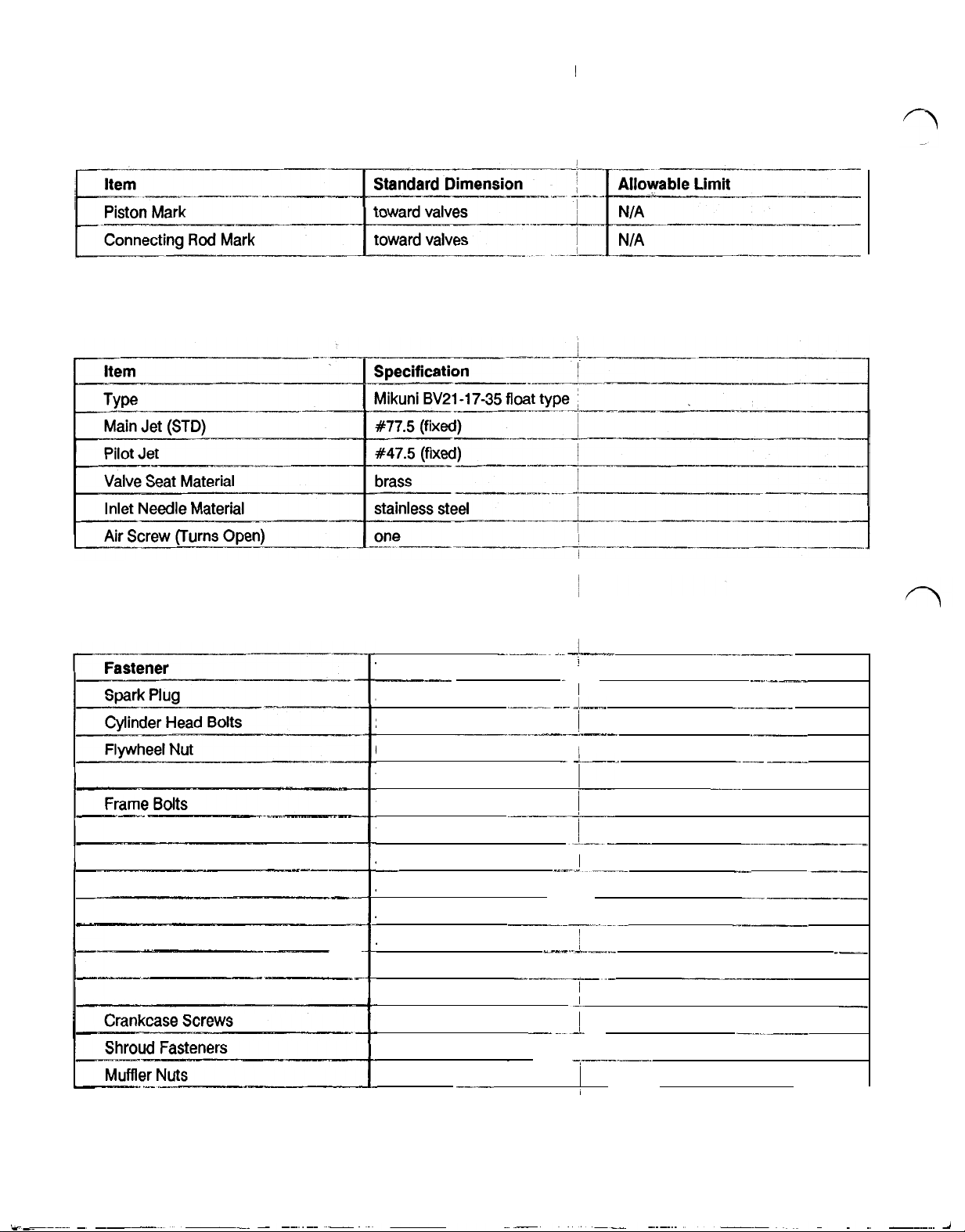
Model 62012 Engine Service Specifications
Standard Dimension
Spark
Plug
Spark Plug Gap
Ignition Coil Air Gap
(External Mount)
Width of Valve
Seat Contact
Intake Guide to Valve
Stem Clearance
NGK BPR-6HS
.75mm
(.030")
.38
(.015”)
fixed
1.OO
to
1.40
mm
(.039
to
.055”)
.80
to
1.OO
mm
(.032
to
.040")
.050
mm
(.002”)
NIA
.025
to
.055
mm
(,0010
to
.0022")
Allowable Limit
NIA
NIA
!
N/A
NIA
.030
mm
(.0012")
.080
mm
.0032
"
Page 13

TI200
SPECIFICATIONS
(cont'd)
Model
62012
Stem Clearance
Bearing Diameter (Big End)
Side Clearance (Big End)
Engine Service Specifications (cont'd)
35.5
to
25.990
.005
to
36.5
to
26.000
.025
mm
mm
mm
Cylinder Distortion
5
Page 14
TI200
SPECIFICATIONS
(cont'd)
Model
Model
62012
62012
Engine Service
Carburetor
Specifications
Specifications
(cont'd)
Model
62012
Fastener
Torques
Torque
.88
2.0
6.5 kg
.7
kg
1.3
1.O
.88
.88
50
.75 kg
.22
.88
.88
55
kg m (6.4
kg m (14.5
m
(47
ft
m
(5.0
ft
kg m (9.4
kg
m
(7.2
kg m (6.4
kg m (6.4
kg
m
(3.6
m
(5.4
kg
m
(1.6
kg m (6.4
kg m (6.4
kg m (4.0
ft
Ibs)
ft
ft
ft
ft
ft
ft
ft
ft
ft
ft
Ibs)
ft
Ibs)
Ibs)
Ibs)
Ibs)
Ibs)
Ibs)
Ibs)
Ibs)
Ibs)
Ibs)
Ibs)
Ibs)
i
I
!
!
1.1
kg
m
(8.0
ft
6
Ibs)
i
Page 15
TI800
SPECIFICATIONS
Model
62018
Product Specifications
Specification
air cooled 4-stroke, side valve
66
mm (2.60")
56
mm (2.20”)
191.6 cc (11.69 cu. in.)
2.8 kilowatt (3.8
counterclockwise (as viewed from
aluminum with
ball
ball
plain
float
unleaded regular gasoline
7.00
liters (1.84 gal.)
5.0
hours at rated load
I
-
-
-
HP) @ 3600 rpm
-
~
cast
iron liner
-
PTO
end)
-
-I---
_
___I___
_
_
_
I
Model
6201
transistorized
25°
BTDC
NGK
BPR-6HS
recoil
splash
.7 liters (23.7 oz)
detergent
float type
3600 rpm
3000
rpm
oiled foam type element
40
kg
(88.5
54.1
x 33.7 x48.5 cm (21.3 x 13.3 x 19.1 in)
8
Generator Specifications
@
3600 rpm
SAE
10W30 or' 30,
Ibs)
-
~~
I
--------_-
API
rating of
-
____
SC,
SD,
-~-
I
__
SE,
_
_I_
or
-
-
_
-
SF
_
_
___I_
-
7
Page 16

TI
800
SPECIFICATIONS
Model 6201 8 Generator Specifications (cont'd)
Specification
12.5 amperes.
12 volts DC
8.3
Amperes
1.5
KVA
(kilovolt amps)*
Maximum Power
1.8
KVA
60Hz at
3600
RPM
(kilovolt amps)
3600
RPM
(cont'd)
i
revolving field, self
1
.o
-
excited
directly coupled to engine
Automatic Voltage Regulator
*
1
KVA
=
1000
Watts true power with
electronic solid state design.
a
power factor of one.
Model 6201 8 Engine Service Specifications
Item
Spark Plug
Spark Plug Gap
Ignition Coil Air Gap
(External Mount)
Ignition Coil Air Gap
(Internal Mount)
Valve
Margin
NGK
BPR-6HS
75
mm
(.030")
1.35
to
(.053
to .073")
1.85
mm
!
Width
of
Valve
Seat Contact
Valve
I
Lash
-
Valve Head Runout (Both)
_
I
-
Intake Guide to Valve
Stem Clearance
_____-_
.80
to
1
.OO
mm
(.032
to
.039')
.050
mm
(.002”)
N/A
,025 to
(.0010
.055
to .0022")
mm
8
_._
I
-
Page 17
TI
800
SPECIFICATIONS
(cont'd)
Model
62018
Item
Exhaust Guide to Valve
Stem Clearance
Valve Spring
Free Length
Cam Height
Intake and Exhuast
Connecting
Journal Diameter
Connecting
Bearing Diameter (Big End)
Connecting
Oil Clearance
Connecting
Side Clearance (Big End)
Piston Pin Clearance
in Connecting
Cylinder Diameter
Piston Measuring Point
Engine Service Specifications (cont'd)
Rod
Rod
Rod
Journal
Rod
Rod
Standard Dimension
.035
to
.065
mm
(.0014
to
.0026')
to
36.5
35.5
(1.398
32.465
(1.2781
25.990
(1.0232
26.005
(1.0238
.005
to
(.0002
.200
to
(.0079
to
.006
(.0002
mm
to
1.437")
to
32.505
to
1.2797")
to
26.000
to
1.0236')
to
26.01
5
to
1.0242")
..025
mm
to
.OOlO”)
.900
to
.0354')
.019
mm
to
.0008)
mm
mm
mm
N/A
15
mm
(59')
I
~-.
-
Piston Diameter
Piston to Cylinder
Clearance
Cylinder Distortion
Piston Ring End Gap
(Compression Rings Only)
Oil Ring
End Gap
Piston Ring Side Clearance
(Top Ring Only)
Piston Ring Side Clearance
(2nd Ring Only)
Piston Ring Thickness
(Compression Rings Only)
Piston Ring Groove Width
(Compression Ring Grooves Only)
NIA
.045
to
(.0018
NIA
.200
to
(.0079
.20
to
(.008
to
.020
to
(.001
to
.020
to
(.001
to
to
1.97
(.0776
to
2.01
(.0791
.065
to
.0026')
.400
to
.0158')
.40
mm
.016')
.060
.003')
.060
.003")
1.99
to
.0783")
2.03
to
.0799")
mm
mm
mm
mm
-_._---
mm
mm
9
Page 18

TI800 SPECIFICATIONS
(cont'd)
Model 62018 Engine Service Specifications (cont'd)
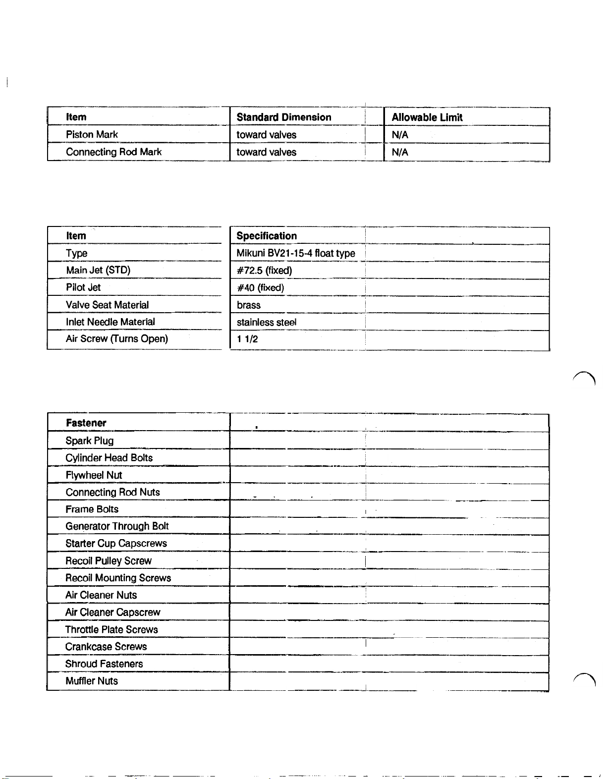
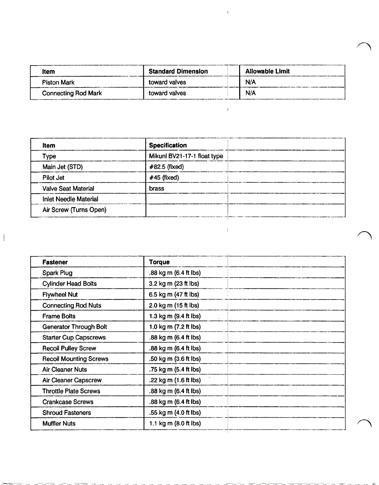
Model 62018 Carburetor Specifications
Item
#75 (fixed)
#40
(fixed)
I
Main Jet
Pilot Jet
(STD)
Model 62018 Fastener Torques
Fastener
Spark Plug
Cylinder Head Bolts
Flywheel
Connecting
Nut
Rod
Nuts
Frame Bolts
Torque
.88
kg
2.0
kg
6.5 kg
.70 kg
1.3 kg
rn
rn
rn
rn
rn
(6.4
(15
(47
(5.1
(9.4
ft
ft
ft
ft
ft
Ibs)
Ibs)
Ibs)
Ibs)
Ibs)
I
I
I
i
-
.I
I
_
-
..~
-
~
-
-
Generator Through Bolt
Starter
CUP
Capscrews
Recoil Pulley Screw
Recoil Mounting Screws
Air Cleaner
Nuts
Air Cleaner Capscrew
Throttle Plate Screws
Crankcase Screws
Shroud Fasteners
Muffler
Nuts
1.O
kg
rn
(7.2
.88
kg m (6.4
.88
kg m (6.4
.50
kg
rn
(3.6
.75 kg
rn
(5.4
.22
kg
rn
(1.6
.88
kg
rn
(6.4
.88
kg
rn
(6.4
.55
kg m (4.0
-
1.05 kg m (7.6
ft
Ibs)
ft
Ibs)
ft
Ibs)
ft
Ibs)
ft
Ibs)
ft
Ibs)
ft
Ibs)
ft
Ibs)
ft
lbs)
ft
io
-
Ibs)
-
---.___.___
I
_I_
-
I
-
-
~
-
_
-
-~______
-
Page 19

T2500 & T2500D
SPECIFICATIONS
Models
62025 & 62027
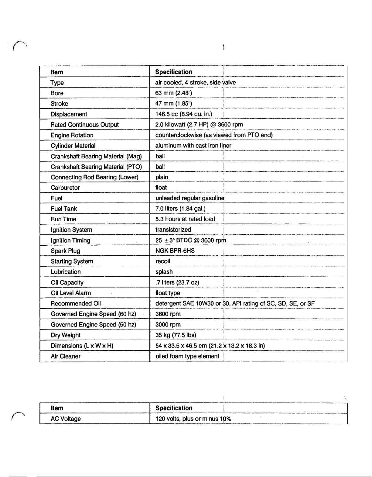
Item
Type
Bore
Stroke
Displacement
Rated Continuous Output
Engine Rotation
Cylinder Material
Crankshaft Bearing Material (Mag)
Crankshaft Bearing Material (PTO)
Connecting
Rod
Bearing (Lower)
Carburetor
Fuel
Fuel Tank
Run Time
Ignition System
Product Specifications
Specification
air
cooled,
72 mm (2.83
62 mm (2.44
4-stroke, side' valve
"
)
"
)
252.4 cc (15.40 cu. in.)
3.7 kilowatt
(5.0
counterclockwise (as viewed from PTO end)
aluminum with cast iron Sleeve
ball
ball
plain
float
unleaded regular gasoline
11
.O
liters (2.91 gal.)
5.0
hours at rated load
-
transistorized
I
_I-
HP) at 3600 rpm
___
_._
----__
~
-
I
Ignition Timing
Spark Plug
Starting System
Lubrication
Oil Capacity
Oil Level Alarm
Recommended Oil
Governed Engine Speed
Governed Engine Speed
Air Cleaner
Dry Weight
Dimensions (L
Model
62025 & 62027
x
Item
W
x
H)
@
25° BTDC
3600 rpm
NGK BPR-6HS
recoil
splash
.O
liters (33.8
1
oz)
float type
SAE
10W30or'30,
(60
(50
hz)
hz)
detergent
3600
rpm
3000
rpm
oiled foam type element
52.8 kg (1 16.5 Ibs)
56.6
x
36.3 x 53.6 cm (22.6 x 14.3 x 21.1 in)
Generator Specifications
Specification
I
i
API
rating of SC, SD, SE, or SF
I
-..-_-
-
I
-
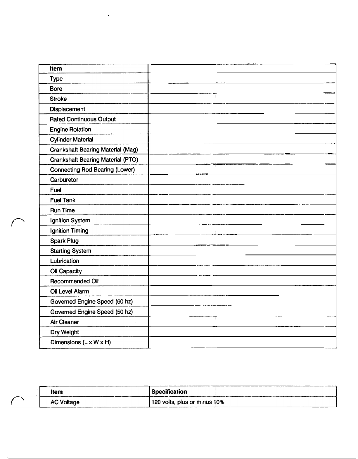
AC Voltage
120
-
220 volts, plus or minus 10%
Page 20
T2500 & T2500D SPECIFICATIONS
Models 62025 & 62027 Generator Specifications :(cont'd)
(cont'd)
Models 62025
Item
Spark Plug
Spark Plug Gap
"
___I-
Ignition Coil Air Gap
(External Mount)
Ignition Coil Air Gap
(Internal Mount)
Valve
Margin
Width of Valve
Seat Contact
Valve
Lash
Valve Head Runout (Both)
&
62027 Engine Service Specifications
N/A
.030
mm
(.0012”)
Intake Guide to Valve
Stem Clearance
12
.080
mm
.0032
"
Page 21
T2500 & T2500D SPECIFICATIONS
(cont'd)
Models
ecting
62025 & 62027
Guide
to
Valve
Rod
Journal
Engine Service Specifications (cont'd)
Standard
.040
39.5
(1.2784
27.991
28.013
(1
.1029
.013
(.0005
.400
.006
to
to
40.5
to
to
to
.036”
to
to
.800
to
.019
.070
to
28.000
28.027
to
.0014")
Dimension
mm
mm
1.2800')
mm
mm
1 1
034")
mm
mm
iston Ring End Gap
8.0
mm
0.200
to
(0.0079
0.20
to
0.030
to
(0.001
to
0.020
to
(0.001
to
to
2.46
2.51
to
(.0988
to
0.400
mm
to
0.01
58')
0.80
mm
0.070
mm
0.003')
0.060
mm
0.003")
2.48
mm
2.53
mm
.0996”)
13
Page 22
T2500
&
T2500D
SPECIFICATIONS
(cont'd)
Models
Models
62025 & 62027
62025 & 62027
Engine Service Specifications (cont'd)
Carburetor Specifications
Models
Connecting
Generator Through
Starter Cup Capscrews
Recoil Pulley Screw
Recoil Mounting Screws
Air Cleaner Nuts
Air Cleaner Capscrew
Throttle Plate Screws
62025 & 62027
Rod
Nuts
Bolt
Fastener Torques
Torque
.88
;__-
kg m (6.4
2.5
kg m (19
6.5
kg m (47
1.8 kg
1.3 kg
1.O
kg m (7.3
.88
kg m (6.4
.88
kg m (6.4
.50
kg m (3.6
.75 kg m (5.4
.22 kg
.88
kg m (6.4
.88
kg m (6.4
.55
kg m (4.0
1.1 kg
m
m
m
m
(13
(9.0
(1.6
(8.0
ft
ft
ft
ft
ft
ft
ft
ft
ft
ft
ft
ft
ft
ft
ft
Ibs)
Ibs)
Ibs)
Ibs)
Ibs)
Ibs)
Ibs)
Ibs)
Ibs)
Ibs)
Ibs)
Ibs)
Ibs)
Ibs)
Ibs)
-__I.
-~.-
-
I
i
i
i
I
-
I
__-
-
__
-
14
Page 23

T3000
Models 62030 & 62032 Product Specifications
&
T3000D
SPECIFICATIONS
Model 62030
&
62032 Generator specifications
15
Page 24

T3000 & T3000D
SPECIFICATIONS
Models 62030 & 62032 Generator Specifications' (cont'd)
(cont'd)
Models 62030
Ignition Coil Air Gap
Ignition Coil Air Gap
Width
of Valve
Valve Head Runout
&
62032 Engine Service Specifications
Standard Dimension
NGK
BPR-6HS
.75mm
(.030')
.38
(.015”)
fixed
.95
to
1.45 mm
to
to
1.10 mm
to
mm
.057")
.043")
(.037
.90
(.035
.050
(.002”)
(Both)
N/A
i
!
i
!
i
I
i
i
I
N/A
N/A
N/A
.030
mm
(.0012”)
I
.025
(.0010
to
to
.055
mm
.0022")
.080 mm
.0032”
16
Page 25

T3000
&
T3000D
SPECIFICATIONS
(cont'd)
Models 62030 & 62032 Engine Service Specifications (cont'd)
Exhaust Guide to Valve
Rod
ecting
Journal
.040
to
(.0016
to
to
39.5
(1.555
to
32.472
(1.2784
27.991
(1.1020
28.01 3
(1.1029
.013
to
(.0005
to
.400
to
(.0158
to
to
.006
(.0002
to
NIA
8.0
mm
(.32")
.070
mm
.0028')
40.5
mm
1.595")
to
32.51 2
to
1.2800”)
to
28.000
to
1.1024")
to
28.027
to
1.1034")
.036
"
.0014')
.800
.0315")
.019
mm
.0008)
mm
mm
mm
mm
I
i
Piston
Ring
End
Gap
NIA
.030
to
.050
(.0012
to
.0020”)
NIA
.20
to
.40
mm
(.008
to
.Ol6”)
to
.80
.20
(.008
.030
(.001
.020
(.001
2.46
(.0969
2.51
(.0988
mm
to
.032")
to
.070
to
.0003”)
to
.060
to
.003")
to
2.48
to
.0976')
to
2.53
to
.0996”)
mm
mm
mm
mm
mm
!
-
,.~
-
17
Page 26
T3000 & T3000D
SPECIFICATIONS
(cont'd)
Models 62030 & 62032 Engine Service Specifications (cont'd)
Models 62030
&
62032 Carburetor Specifications
stainless
1
1/4
steel
Models 62030 & 62032 Fastener Torques
18
Page 27
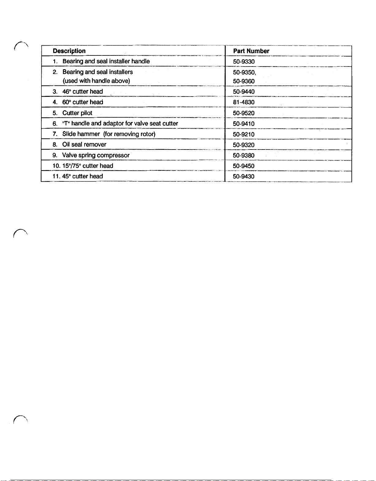
SPECIAL TOOLS
19
Page 28

TROUBLESHOOTING
Engine Does Not Produce Spark
Possible Causes
engine switch in “off’ position
spark plug fouled or damaged
spark plug wire damaged
ignition coil primary wire grounding out
ignition coil has failed
Engine Floods During Starting
Possible Causes
no spark
stale gasoline
I
engine overchoked
choke not opening
I
1
leaking needle/seat
water in fuel
I
plugged air filter
Remedy
I
move switch to “on” position
replace spark plug
replace coil
repair damaged wire with electrical tape
replace ignition coil
Remedy
see “Engine Does Not Produce Spark’
troubleshooting section above
fill tank with fresh unleaded gasoline
open choke, close fuel shutoff valve
and turn over until engine fires
replace damaged parts
I
1
clean carburetor and pressure check
1
drain tank and fill with fresh gasoline
clean air filter
I
I
I
I
I
Engine Does Not Get Fuel During Starting
Possible Causes
fuel shutoff closed
fuel tank empty
plugged fuel line or filter
fuel cap not venting properly
r-~---
* For generating troubleshooting information, see Section 7, page 74.
20
Remedy
open fuel shutoff valve
fill fuel tank with fresh unleaded gasoline
clean or replace plugged component
repair or replace fuel cap
I
I
Page 29

TROUBLESHOOTING
(cont'd)
Engine Difficult
I
engine not getting fuel
engine
Engine Lacks
Possible
choke partially closed
has
low compression compare compression to compression of
Power
Causes
to
Start
Remedy
see "Engine Does Not Produce Spark”
troubleshooting section (page
see "Engine Does Not
Starting
see "Engine Floods During Starting
troubleshooting section (page
new unit
Remedy
open choke
adjust carburetor
"
troubleshooting section (page
--
repair as necessary
Get
8)
Fuel During
"
8)
8)
lack
of
lubrication
Engine Knocks
replace flywheel key
fill crankcase with proper lubricant
clean or replace air cleaner
grind valves and set valve lash
see
"
Generator Troubleshooting Guide",
page
74
compare compression to new unit
and overhaul
Remedy
.__^_.--
clean carbon from combustion chamber
replace damaged or worn parts
tighten flywheel nut
-
-
__
tighten rotor bolt
replace key
___
if
necessary
-
-
_I-
__
-
*
For generating troubleshooting information, see Section
21
7,
page
74.
Page 30

TROUBLESHOOTING
Engine Misses Under Load
Engine Overheats
(cont’d)
Engine Surges or Runs Unevenly
*
For generating troubleshooting information, see Section
7,
page
74.
22
Page 31

TROUBLESHOOTING
Engine Vibrates Excessively
(cont'd)
Engine Uses Excessive
*
For generating troubleshooting information, see Section
Oil
or
Smokes
7,
page
replace damaged
tighten engine mounting bolts
Remedy
set engine to proper speed
drain excess oil
ensure that cap does not pass oil or air
replace damaged or worn parts
overhaul engine
74.
parts
23
Page 32

MAINTENANCE
Maintenance
The air cleaner should be serviced every
Maintenance may have to be completed as often as
every 25 hours
or dusty conditions.
1. Shut the generator off and close the fuel shutoff
valve.
2. Remove the thumb screw retaining the air cleaner
cover. See Figure 1.
Remove the dust cup, baffel, foam element and
3.
element holder.
4.
Wash the element in soap and water or
made for cleaning air cleaner elements.
Air
Cleaner
50
hours.
if
the generator is being operated in dirty
Figure
1
a
solvent
Maintenance
The spark plug is the ignition source for
in the combustion chamber of the engine. The engine
will not run properly
replaced
cleaned;
spark plug cleaners will leave grit on the plug that can
cause rapid :engine wear.
Type:
Substitute: Champion L92Y/L92YC
Maintenance Changing Oil
Tor0 generators are shipped without oil.
generator until you have added the correct amount of
Service Classification
Oil change frequency:
I
1. Stop the engine and remove the spark plug wire
from the spark plug.
2.
Remove the oil
3.
Position and drain pan under the engine and
remove the drain plug.
Spark
a8
required. Spark plugs should not be
if
the plug is fouled or dirty, replace
Plug
the
if
the spark plug is not inspected and
NGK BP-
5HS
I
.6-.7mm (.024-.028')
-
Every 100 hours
-
105 Kg-cm (80-120
70
-
lbs)
in
Do
not start the
see spec. on page
30
summer
20 fall, spring
10 winter
MS,
SC,
SD,
SE
fill
After the first
every
plug.
See
50
Figure 2.
20
hrs. thereafter.
fuel air mix
it.
Abrasive
_
-
3
hrs. and
~_~..~~
5.
Squeeze the element dry
Saturate the element with
6.
then squeeze the excess oil out of the element.
Note: an element that is too heavily saturated with
oil may restrict air flow and cause a rich running
condition for the engine.
7.
Reinstall the element holder, foam element, baffel
and dust cup.
Secure the air cleaner cover with the single
8.
mounting screw.
Make sure the breather hose is properly connected
9.
to the body of the air cleaner.
of
the cleaning solution.
30
weight motor oil and
24
Page 33

5.
Maintenance - Changing Oil (cont’d)
4.
Reinstall the drain plug and dispose of the used oil
at a proper waste oil disposal site.
r
‘,
5.
Fill the crankcase with oil. See the Specification
Section on page 3 for the proper quantity. When
replacing the oil it will be helpful to tilt the generator
back about
the filler neck without spilling. See Figure 3.
100-15’,
-__1_
this will allow the oil to enter
-----
t
Empty the fuel bowl and clean it of any debris.
6.
The filter screen is located in the head of the bowl
and may be removed and cleaned at this time. See
Figure 4.
7.8.On reinstallation make sure the screen is properly
seated to prevent unfiltered fuel from entering the
carburetor.
Reinstall the sediment bowl and tighten the plastic
collar.
9.
Turn the fuel valve back on and visually check for
leaks.
SCREEN
r
----.
Figure 3
.-----l_l___
\
Maintenance - Fuel Sediment Bowl
The
T1200 - T3000
sediment bowl and strainer that will filter debris from the
fuel and will trap water before the fuel reaches the
carburetor. The sediment bowl should be cleaned at
least once a season.
Cleaning the fuel sediment bowl will require working with
gasoline.
presence of gasoline. Always keep gasoline in
a container designed for the storage of
flammable liquids.
1.
Stop the engine and remove the spark plug wire.
2.
Close the fuel shutoff valve.
3.
Prepare a drain pan to catch a small amount of
gasoline that may be spilled or released when the
fuel bowl is removed.
4.
Unscrew the plastic’collar retaining the fuel bowl
and pull the fuel bowl off the head assembly.
generators are equipped with a fuel
CAUTION: Misuse of gasoline
can cause death. Do not work
with gasoline around open
flames. Do not smoke in the
10.
Return the valve to the “off’ position when the
cleaning and inspection are complete.
Maintenance - Frequency Adjustment
All Toro generators including the T1200 designed to run at a speed of 3600 rpm. The frequency
of the
el,ectricity
speed) 60 cycles of alternating current per second
(6OHz); ,This
revolutions per second or 3600 rpm.
~~~~~~~~~~-~~
1.
Check the engine oil level.
2.
Disconnect any load that may be connected to the
generator.
3.
Start the generator.
4.
5.
/
Connect a load to the generator that is similar to
the load the generator is normally under when
used by the customer.
Adjust the speed of the engine with the speed
adjustment screw to 3600 rpm. The speed adjust-
produced is (controlled by the engine
is, of course, the same as 60 engine
T300O
are
Page 34

Maintenance Frequency Adjustment (cont'd)
ment screw is located behind the air cleaner and
connects
6.
With the engine at 3600 rpm the
front of the generator will resonate. (some models
are not equipped with a frequency meter.) See
Figure
to
the governor arm.
5.
60Hz
MENT
reed on the
SCREW
closing completely and the valve clearance will have
be adjusted.
.05-.15
for both intake and
exhaust valves.
Adjustment Frequency: Every
I
Maintenance Valve Clearance Inspection
1.
Stop /the generator and remove the spark plug
wire.
Close the fuel shutoff valve.
2.
Remove the single screw retaining the air cleaner
3.
to
bracket
Remove the two screws retaining the air cleaner
4.
assembly
5.
Pull
Remove the two screws retaining the breather
6.
assembly
the engine block.
to
the carburetor.
the breather hose
off
mm
(.002-.006”)
300
hrs
the breather assembly.
to
I
7.
The speed of the engine may also be set using a
variety of tachometers. Once the engine speed is
adjusted
be set at
Maintenance Valve Clearance
The
T1200
The valves are opened and closed with solid cam
followers. If the clearance between the end of the valve
stem and the cam follower is
close. The clearance is factory set at
(.002-.006'”).
face may wear causing the valve stem and follower
clearance
degrades after many hours of use, the valves may not be
to
3600
rpm the electrical frequency will
60
Hz.
T3000 generators use side valve engines.
too
small the valve may not
.05-.15
After many hours of use the valve seat and
to
decrease. If the performance of the engine
mm
Remove the breather assembly. Take note of how
7.
the gaskets and reed plate are installed.
Measure the valve clearance with the engine cold
8.
and on top dead center (TDC) of the compression
stroke. See Figure
To determine TDC; remove the spark plug and
place: a clean wooden dowel
opening
Rotate the engine until both valves are closed
(watch the cam followers
When both valves
reaches the highest point
of the
with more accuracy by using a depth reading dial
indicator.
so
the dowel rests on the top of the piston.
compression
6.
Figure
6
in
the spark plug
in
the breather opening.)
stop
moving as the dowel
in
its
travel you have TDC
stroke. TDC can be determined
26
Page 35

Maintenance Valve Clearance Inspection (cont'd)
9.
The correct clearance is .05-.15 mm (.002-.006'”).
If the clearance is not within tolerance, the valves
must be removed from the engine and the
approprlate
amount
of material ground
off
the stem
of the valve.
Maintenance Valve Clearance Adjustment
1.
Follow steps
2.
Remove the fuel hose from the carburetor.
3. Remove
front control panel. See Figure
1
7
as described above.
two
hair pin clips from the bottom of the
7.
Remove the valves.
9.
After the valves are removed the ends of the stems
10.
should be ground to provide
the
required
clearance.
11.
Check the condition
face. Recondition the face and seat
12.
Reinstall the valves and keepers.
Reinstall the head of the engine. Consult the
13.
of
the valve seat and valve
if
necessary.
Specification Section for correct head bolt torque.
14.
Replace the metal shield over the cylinder head of
the engine. This shroud is part of the cooling
system and must be properly installed.
Remount the fuel tank with the four hair pin clips.
15.
Install the fuel hose on the carburetor.
16.
1
7.
Reinstall the spark plug wire.
Maintenance Decarboning Spark Arrester
All
Toro generators are fitted with spark arresting
mufflers.'
If
the spark arrester is not serviced, the ability
of the engine to exhaust will be restricted and the
performance of the generator will drop.
4.
Remove
two
gasoline tank. See Figure
Figure
hair pin clips from the bottom of the
7
8.
I
Figure
5.
Lift
the tank and front panel assembly forward and
away from the head of the engine.
6.
Remove the screws retaining the metal shield on
the head of the engine (three screws on the T1200,
T1800
and four on the T2500, T3000).
7.
Remove the screws retaining the head of the
engine.
8.
Use a valve spring compressor to remove the valve
keepers.
8
Decarboning
Interval: 100 hrs
1.
Stop the engine.
2.
Remove the spark plug wire.
3. Remove the
Figure
4.
Remove the single screw retaining the spark
9.
two
spark arrester clean
Figure
9
out
-__^_-
arrester tube in the end of the exhaust pipe and pull
the tube out of the pipe. See Figure
5.
Take the generator to a well ventilated area that is
9
free of combustible material.
6.
Start the generator and tap on the side of the muf
bolts.
above.
See
-
27
Page 36

Maintenance Decarboning Spark Arrester (cont'd)
fler to dislodge any carbon build up within the
spark arrester.
CAUTION: Exhaust fumes can
cause death. Operate the
generator only
ventilated area.
CAUTION: The muffler will
cause burns if
7.
Allow the muffler to cool. Remove any remaining
carbon from the clean out ports and the exhaust
discharge opening.
8.
Reinstall the muffier clean out bolts.
10.
Reinstall the spark arrester.
Maintenance Storage
If
the generator is not going to be used for a period of
three months or more the following long term storage
procedures should
1.
Drain all gasoline from the fuel tank into a container
designed for storing flammable liquids.
be
completed:
In
it
is touched.
a well
CAUTION: Misuse of gasoline
can cause
while working with gasoline.
Never expose gasoline to open
flame or fire.
working
while'
2.
Start
the generator and run the remaining fuel out
of the
carburetor.
Turn the engine over
3.
feel the resistance of compression; this will
indicate that both valves are in'
sealing the cylinder.
4.
Drain :the existing engine oil and refill the engine
with fresh oil.
5.
Remove the spark plug and pour one or
tablespoons of
plug.
6.
Service the air cleaner element. See the
instructions on page
maintenance
7.
Check the tightness of all fasteners.
8.
cover the generator and put
Always
with gasoline.
with
oil
into the cylinder and replace the
death.
use
the recoil starter until you
24
Never smoke
proper ventilation
the
closed position
on air cleaner
it
away for storage.
two
28
Page 37

SECTION
1
CARBURETOR
Carburetor Operation
The carburetor receives fuel from the gasoline tank and
mixes
it
with air in the right proportions to provide a
highly combustible mixture to the engine.
As
the piston moves up on the compression stroke, a
partial vacuum is created within the engine crankcase,
causing the greater atmospheric pressure to force air to
flowthrough the carburetor into the cylinder. Thevelocity
of the air increases as
it
flows through the carburetor
venturi and the air pressure is reduced at this point to
less than atmospheric pressure. The low pressure in the
venturi of the carburetor causes atmospheric pressure
to push raw fuel from the float bowl into the air stream in
the throat of the carburetor, where
it
breaks up into a fine
spray, or becomes atomized, and mixes with the air
stream.
See
Figure
Atmospheric
Pressure
10.
,Venturi
from the float bowl. This fuel premixes with the incoming
is
air, then
See Figure
discharged into the intake port of the engine.
12.
Pilot System
Pilot Jet
,Pilot Air Fitting
COLD
START
Figure
11
Carburetor
Bore
Float Bowl
To
Engine
When starting the engine an extra rich mixture is
is
required. The choke plate
provide an approximate
closed by the operator to
8:l
ratio of fuel to air for this rich
mixture. Closing the choke plate further reduces the air
pressure in the venturi to increase the fuel pushed into
the carburetor throat. In this condition fuel also flows
from the float bowl through the pilot system ports as well
as the main discharge tube to achieve the proper starting
mixture.
See
Figure
11.
Fuel atomization becomes more efficient, due to heat,
once the engine has reached normal operating
temperature. As a result the engine does not require the
rich mixture
it
did for starting and the choke plate must
be moved to the open position. The engine speed is now
regulated by the throttle plate. In no load conditions a
small portion of the fuel may be drawn from the main
fuel
discharge tube, however the primary
from the pilot circuit. Air passing through the pilot
the pilot air fitting draws fuel
out
supply is drawn
jet
from
of the pilot jet orifice
Pilot System /Pilot Jet
Fitting
NO
LOAD
Figure
12
As the throttle plate is opened to compensate for engine
load, the main discharge tube becomes the main source
of fuel. Opening the throttle plate increases the flow of
air through the venturi and strengthens the low pressure
area at the main discharge tube. Fuel discharge
increases at the main discharge tube as it decreases
from the pilot system. Air is drawn from the air correction
jet
through holes along the length of the main discharge
tube. This premixes air with the fuel before
it
enters the
29
Page 38

Carburetor Operation (cont'd)
carburetor throat for more efficient atomizing of the fuel.
See
Figure
Throttle
Main
Plate
Discharge
Tube
13.
Float
,Pilot System
UNDER
Correction Jet
LOAD
7.
Slide /the carburetor off
its
studs and disconnect
the governor link rod.
8.
There will be a small amount of gasoline in the bowl
of the carburetor. Drain this gasoline into a
suitable container by opening the drain screw on
the bottom of the carburetor.
CAUTION: Mishandling
gasoline can cause death.
Always work with gasoline in a
well ventilated area free
Do
flame or sparks.
not smoke around
gasoline
Carburetor Disassembly
1.
Remove the carburetor bowl nut.
necessary to remove the drain screw.
15.
of
It
See
open
is not
Figure
Figure
13
Carburetor Removal
1.
Stop the generator and remove the spark plug
wire.
2.
Close the fuel shutoff valve.
3.
Remove the single screw retaining the air cleaner
body to the engine block.
4..
Remove the'
two
screws retaining the air cleaner to
the carburetor.
5.
Remove the fuel inlet hose.
6.
Remove the two nuts retaining the carburetor to
the
engine. See Figure
14.
Figure
15
Figure
14
30
2.
The main
jet
is threaded into the carburetor bowl
nut. The float and inlet needle may be removed by
pulling out the float hinge pin. Note: one end of the
hinge'
pin
is flattened slightly. The pin must be
removed from this end. See Figure
3.
The pilot jet may be removed from the top of the
16.
carburetor and can be cleaned or replaced. Fuel
flows through the small opening in the end of the
Page 39

Carburetor Disassembly (cont'd)
jet and air enters through the holes in the side. The
opening on the top of the jet is a drilling passage
and is plugged.
The pilot screw controls air in the pilot circuit.
should be open 1 to 1 Figure
17.
1/2
turns on all engines. See
t
FLAT
CAUTION: Be sure
safety glasses when using
compressed air. Use pressure
It
3.
If
it
is
suspected that the seat is leaking, the
carburetor can be pressure tested after
cleaned. Use Toro Pressure tester, Number
41-7910.
(7
should be completed with the carburetor turned
upside down
See Figure
the 'needle and try the test again. If the carburetor
fails again, the seat is bad and the carburetor must
be replaced
If
psi) for at least
of no more than
the seat is good,
10
so
the seat holds the needle closed.
18.
If
the pressure leaks down, replace
it
will hold
seconds. This procedure
40
to
PSI.
it
has been
.5
wear
kg/cm
2
Figure
PILOT
Figure
Carburetor Service
1.
The metallic body of the carburetor may be
cleaned in carburetor cleaner. Plastic parts may
be damaged by some carburetor cleaners.
16
17
Figure
Carburetor Reassembly
1.
Replace the main nozzle and bowl gasket.
2.
Install the pilot jet and pilot screw. Refer to Figure
17.
The pilot screw should be open 1 to 1 -
3.
Hook the inlet needle into the float and secure the
float and needle in place with the hinge pin.
Figure
Remount the bowl and gasket.
4.
Carburetor Installation
19.
18
1/2
turns.
See
Carburetor passages may be cleaned
compressed air.
2.
Replace any components that show wear or
damage. The inlet needle is replaceable but the
seat is not.
out
with
31
1.
Mount one gasket, one spacer and one additional
gasket on the carburetor mounting studs.
2.
Connect the tension spring from the governor arm
to the throttle shaft.
Page 40

Carburetor Installation (cont’d)
3.
Connect the governor link rod. See Figure 20.
5.
Straighten the governor arm
allow
connection
of
if
the linkage rod to the
carburetor.
6.
lnstail the carburetor mounting nuts.
7.
Connect the fuel inlet hose.
8.
If
the
~governor
arm has been removed to provide
additional working clearance, make sure
correctly reset.
it
has been bent to
it
is
Figure 19
I
Figure 20
4.
Install the carburetor on the mounting studs.
FLAT
The governor shaft
is
turned
full
counterclockwise
while; the governor holds the throttle plate wide
open.
The governor spring connects in the upper hole
of
the governor arm. See Figure 21.
I
i
Figure 21
14. Remount the air cleaner body to the carburetor
with
two
screws.
15. Secure the air cleaner bracket to the engine block.
Carburetor reinstallation is now complete.
32
Page 41

SECTION
FUEL TANK AND STRAINER
See the Specification Section for
fuel tank and approximate running time under full load.
The required fuel is regular unleaded gasoline.
Fuel Tank and Strainer Removal
1. Shut off the generator.
2. Drain the fuel tank. Remove the line on the inlet side
of the fuel shutoff valve. See Figure 22.
the
capacity of each
2
FUEL
8.
SYSTEM
Examine the fuel tank for debris and wash the tank
with a cleaning solvent
if
necessary.
NOTE:
liquids available to receive the gasoline from the
tank.
flame or sparks. Do not smoke around
gasoline.
Have a container suitable for flammable
Figure 22
CAUTION: Mishandling
gasoline can cause death.
Always work with gasoline in a
well ventilated area free of open
Fuel Tank and Strainer Installation
1.
Install the fuel tank on the front panel.
2. Reset the fuel tank
frame and install the hairpin clips.
3. Connect the fuel hose to the fitting on the shutoff
valve and sediment bowl.
distorted
4. Install the fuel strainer and tank cap.
FUEL
TANK
The fuel tank cap is an important
of the fuel system.
must do:
It
must allow atmospheric pressure into the tank and
must allow any buildup of pressure out of the tank. The
cap also' has to keep fuel in the tank.
it
CAP
It
must keep debris, water, etc., out of the tank.
and
front panel on the generator
If
the clamp is bent or
should be replaced.
but
often ignored part
It
has several important jobs that
it
it
Remove the fuel tank cap.
3.
4.
Pull
the fuel strainer out of the tank.
Examine the fuel strainer for debris and wash it out
5.
in a suitable solvent.
Removethe four hairpin clips retaining the fuel tank
6.
and front panel to the frame of the generator.
7.
Lift
the fuel tank away from the engine and remove
the
five
screws retaining fuel tank to the front panel.
The fuel tank is now separate from the generator.
See
Figure 23.
Fuel Tank Cap Service
1.
Examine the condition of the cap. Look for
distortion or bending.
2.
Examine the gasket. The gasket should indicate an
even seal for a full 360 degrees. The gasket part
number is 53
See
Figure 24.
3.
Make sure the cap is venting properly.
be, able to force air through the cap from the inside
out and the outside in. Replace the cap
not vent properly.
33
-
1420 for T1200 -:T3000 generators.
You
should
if
it
does
Page 42

Fuel Tank Cap Service (cont'd)
Fuel Shutoff and Sediment Bowl Removal
Drain the fuel tank. Removethe line on the inlet side
1.
of
the fuel shutoff valve. See Figure
22
on page
33.
A
STRAINER
NOTE:
liquids available to receive the gasoline from the
tank.
flame or sparks. Do not smoke around
gasoline.
2.
Disconnect the outlet hose from the fuel shutoff
valve.
Fuel Shutoff and Sediment Bowl Service
1.
Complete service of the valve may be
accomplished without removing the valve from
mounting bracket.
2.
Remove the sediment bowl by unscrewing the
collar around the
Have a container suitable for flammable
CAUTION: Mishandling
gasoline can cause death.
Always work with gasoline in a
i
well ventilated area free of open
bowl.
See Figure
26.
its
Figure
24
4.
Install the cap and make sure the tabs on the cap
pull
it
fully against the tank as
FUEL SHUTOFF AND SEDIMENT BOWL
The
T1200
valve and sediment bowl. The valve is mounted to the
tube frame under the fuel tank. See Figure 25.
T3000
generators use a combined shutoff
it
is turned in place.
Figure
3.
Take:
note
that there is a filter screen in the head of
the valve that may be cleaned or replaced as
required. The
See Figure
part
27.
26
number of the screen is
50-3770.
Figure
25
34
4.
The valve may be serviced by removing the set
screw on the side of the valve. Use care, as the
valve stem is under spring pressure and must be
restrained as the set screw is loosened.
Page 43

Fuel
Shutoff
and Sediment
Bowl
Service (cont'd)
6.
When the stem and valve cylinder are removed, the
be
valve may
solvent.
cleaned in a nonflammable cleaning
Figure
27
5.
After the valve stem is removed, the plastic valve
cylinder may be withdrawn with a needle nose
pliers.
SCREEN
Fuel Shutoff and Sediment
1.
Reassemble the valve by inserting the valve
cylinder and stem in the body of the valve. Make
sure the cylinder and hole
up 'with the handle of the valve stem. Restriction
of
fuel flow may occur
indexed correctly.
2.
Install the valve stem retaining screw. Make sure
the valve is free to turn.
likely that the end of the retaining screw is not
located in the slot on the side
The slot is there to limit the rotation
about
90
degrees.
Fasten the valve to its mounting plate with
3.
screws.
4.
Install the inlet and outlet hoses to the valve.
Bowl
If
Installation
in
the
valve
if
the
two
parts
the valve will not turn
of
the valve stem.
of
cylinder lines
are not
it
is
the valve to
two
35
Page 44

SECTION
IGNITION
SYSTEM
IGNITION OPERATION
The firing of the spark plug at the proper time is the
culmination of a number of components working
together. In the T1200 T3000 generator, the
components used are:
Flywheel
Ignition coil
Trigger circuit (molded into the ignition coil)
Spark plug
See
Figure
28.
secondary coil must have many more windings than the
primary. The higher the ratio between the primary coil
to secondary coil windings, the greater the voltage
amplification will be.
Figure 28
The following describes the function of each of the above
components.
Ignition Operation Flywheel
The engine flywheel is the generating force for the
ignition system.
Imbedded in the flywheel are permanent magnets. These
magnets rotate past the coil to generate electricity.
Imbedded in the opposite side of the flywheel is a steel
counterweight which offsets the weight of the three
magnets.
Ignition Operation Ignition Coil
The ignition coil is actually a transformer. It is positioned
close to the flywheel to allow the magnetic field of the
flywheel magnets to cut through the coils to generate
electricity. See Figure
Low voltage is produced in the primary coil which is sent
to the trigger circuit. This voltage would be much too low
to produce a spark at the spark plug.
It
is not magnetic.
29.
I
Figure 29
Even though the secondary coil has considerably many
more windings than the primary, the voltage produced
is still not high enough to produce sparkacross the spark
plug electrodes To further amplify the voltage, the
trigger circuit is used.
Ignition Operation Trigger Circuit
The trigger circuit amplifies the voltage in the secondary
coil by breaking the primary circuit just as the primary
its
voltage reaches
circuit results in a rapid collapse
surrounding g the primary coil. The collapse of the primary
magnetic field induces a large voltage surge in the
secondary' which is sufficient to produce a spark across
the spark plug electrodes.
Before getting into the actual electronics used inside the
trigger circuit,
of the voltage waveform produced by the flywheel
magnets moving by the ignition coil.
As
the magnets rotate past the coil, voltage is produced.
This voltage,' when uninterrupted, is first positive, then
negative as the magnet passes by the coil. This effect is
caused by the two opposing poles
peak. This breaking of the primary
of
the magnetic field
it
is important to have an understanding
See
Figure 30.
of
the magnet.
The secondary coil serves to amplify the voltage
produced in the primary. To accomplish this, the
Explanation of the trigger circuit also requires an
understanding of the
NPN
transistor. See Figure 31.
36
Page 45

Ignition Operation Trigger Circuit (cont'd)
3.
Current
current,
12
that
I1
flowing through Tr2 induces a larger
l2.
Note that current
is much larger.
MTI
unit Ignition coil
See
I1
is very small and
Figure
34.
PRIMARY
B
VOLTAGE
Figure
(Base)
30
WAVEFORM
C
(Collector)
E
(Emitter)
NPN-type
Figure
31
A
transistor has a certain minimum voltage that
requires across the base and emitter (points B and E in
it
the Figure above) before
turned on
above.
current,
current
11.
Thus, the transistor functions as an amplifier in that it
it
allows a small current,
At
the same time the transistor allows a large
12,
to flow from point C to
12
will vary in proportion to the smaller current,
will "turn on". Once
11.
to flow as shown
E.
The magnitude of
allows a small current to control a large one.
it
has
!
MTI unit Ignition coil
Figure
Figure
MTI unit Ignition
it
4.
When the voltage is at the point "a" level as denoted
above in Figure
30,
allows no current
MTI
unit Ignition
32
33
Trl is still in the
13
or
14
to flow.
coil
"
off'
See
coil
Ground
Spark plug
mode and
Figure
35.
The following is the process the trigger circuit uses to
break the primary circuit to produce spark:
1.
The magnet passes by the coil and induces an
alternating voltage.
2.
As
the voltage begins to increase (approximately
point
"a"
in Figure
and current flows from point
R3, R4,
and Tr2.
See
Figure
32.
30),
transistor Tr2 is turned on
"c"
to point "d" through
See
Figure
33.
Spark plug.
37
Page 46

Ignition Operation Trigger Circuit (cont'd)
5.
As the voltage produced in the primary coil
“b”
reaches its negative peak (point
transistor Trl is turned on and allows small current
13
and large current
6.
When transistor Trl turns on, nearly all of the
current flow through
14
path
drop in current
Off.
7.
When Tr2 turns
causes the magnetic field surrounding the primary
coil to rapidly collapse. This in turn causes a
voltage surge in the secondary which is sufficient
to produce a spark across the spark plug.
Ignition Operation
The spark plug is used to ignite the air fuel mixture by
producing a spark just before the piston reaches top
dead center.
shown in Figure
since
A
spark plug is typically constructed as
36.
14
to flow.
R4
and Tr2 is diverted through
it
is the path of least resistance. This
I1
results in transistor Tr2 turning
off,
current
-
Spark Plug
12
in Figure
drops rapidly and
30),
Excessive gap or fouling can delay firing enough to
loss
cause a
The other important area is the insulator. The insulator
prevents arcing from taking place in another portion of
the plug, away from the electrodes. Because
extremely high voltage present, even a slight crack or
fouling of
malfunction of the plug.
IGNITION
Ignition Coil Testing
The operation of the ignition coil should be tested before
.the product' is disassembled.
1.
Shut
appliances that may be plugged into the generator.
2.
Remove the rubber spark plug cover and remove
the sp'ark plug.
Inspect the spark plug and ensure that
3.
condition. Make sure there are no particles
bridging the spark gap.
of power or stalling.
the
head insulator can result in arcing and a
COIL
off
the fuel supply valve and disconnect any
it
is in good
of
the
HEAD INSULATOR
COPPER
LEG
CORE
INSULATOR
4.
Ground the body of the plug on the side of the
engine. Turn the ignition switch on. Pull the starter
cord and watch for a spark at the gap of the plug.
5.
If
there is a strong spark, the ignition module is
intact and working properly.
6.
If
there is a lack of spark, check the oil level in the
engine. The engine uses a low oil shut down device
will
that
low. For operation of the low oil level shut down
device, see Low Oil Shutdown, page
7.
If
connected to the low oil shut down module.
Access to the yellow wire may be obtained by
removing the single screw that retains a wlre
connector bracket on the front crossframe of the
generator.
the wire.
prevent the engine from starting
the
oil
level is normal, disconnect the yellow wire
See
Figure
37
for the exact location
44.
if
the oils
of
GROUND
There are
plug function. The first is that the electrodes are properly
gapped and are clean. This ensures that
will be present and that it occurs
ELECTRODE
Figure
36
two
critical areas important to proper spark
a
strong spark
at
the proper time.
GAP
38
Page 47

Ignition Coil Testing (cont'd)
8. Insulate the wire from ground and attempt to start
the generator.
If
the
ignition has spark the low oil
shut down circuit is at fault. See the section on the
low oil shutdown circuit, page 44.
9
If
the ignition has no spark with the low oil shut
down circuit disconnected the fault is with the
Ignition circuitry and the coil may have to
be
removed. See the section on coil removal below.
Ignition Coil Removal
Stop the generator and remove the spark plug
1.
wire.
Close the fuel shutoff valve.
2.
10. Unplug the black ignition kill wire and and the entire
coil may be removed.
3.
Remove
the
four screws retaining blower housing
of the generator.
Pull
4.
some slack
in
the spark plug wire and remove
the blower housing.
On the T1200 and T1800 the coil is now exposed
5.
and may be removed after unplugging the ignition
kill wire.
T1200 and T1800 generators built in 1983 and all
6.
T2500 and T3000 generators have the ignition coil
mounted on the engine block behind the flywheel.
The flywheel magnets are located on an internal
counterbore in the flywheel. The flywheel must be
removed to expose the ignition coil.
Remove the flywheel nut and the three screws
7
retaining the starter cup.
See
Figure 38.
40
Figure
Ignition
1.
Coil
Installation
Mount the ignition coil on the engine block. On the
T1200 and T1800 an air gap
of
.381 mm (.015")
should be set between the coil and flywheel. On
the T2500 and T3000 and 1983 models
and T1800 that have ignition coils that are mounted
on the engine block behind the flywheel, the
ignition coil location is fixed and no adjustment is
possible
of
T1200
Figure 38
8. Use a puller or remover to remove the flywheel.
See
the section on special tools on page 19, for the
part
correct tool and
number. See Figure 39.
9. The ignition on T2500 and T3000 generators is now
exposed. See Figure
40.
39
2.
Route and secure the spark plug wire in the wire
retainer on the back of the engine block.
On models with internal ignition coils, remount the
3.
flywheel. Make sure the taper on the flywheel and
the taper on the crankshaft are clean. Torque the
flywheel nut to
kg m (43
50
6.0
7.0
engines. See Figure 41.
Remount the blower housing with the recoil starter
4.
attached.
ft
Ibs) on all
Page 48

Ignition
5.
Coil
Installation (cont'd)
Reconnect the Ignition kill wire.
gap on the electrodes of the plug is
.028").
.6
.7
mm (.024
SPARK PLUG
Figure 41
Spark Plug
1. Stop the engine and remove the rubber dust cover.
2. Remove the spark plug wire.
3.
Clean debris from around the spark plug
does not
removed
4. Remove the plug with a 19 mm (3/4”) wrench.
5.
Spark 'plugs should not
cleaners and reused. Grit
the plug and cause engine damage. Dirty spark
plugs
Spark Plug Installation
1.
Use an
spark plug.
2.
Set the plug gap to
3.
Install the plug with a 19 mm
use a release agent
4. Torque the plug to
Removal
fall
into the engine when the plug
Should be replaced.
NGK
BP-5HS
or Champion L92Y
.6
or
oil on the threads
1.2
kg m (8.5
be
cleaned by abrasive
will
eventually fall out of
.7
mm (.024 .028")
(3/4')
wrench.
of
ft
Ibs).
so
dirt
or
L92YC
Do
not
the plug.
is
NGK
The correct spark plug is an
substitute is a Champion L92Y or L92YC. The correct
BP-5HS.
An acceptable
5.
Replace the spark plug wire.
6.
Reinstall the rubber dust cover.
40
Page 49

SECTION 4 RECOIL STARTER
Recoil Starter Removal
1.
Turn
off
the generator, shut
disconnect the spark plug.
2.
Remove the three screws retaining the recoil
starter. Note the position of the recoil handle for
proper reinstallation.
Recoil Starter Disassembly
1.
Begin disassembly by relieving the spring tension
on the reel. Pull approximately 30 cm (12
starter cord out of the reel and hold the reel in
place.
off
the fuel and
"
) of
2. Place the cord in the notch in
release
without rewinding the cord on the reel.
NOTE: The rope is wound around the reel in a
counterclockwise direction as you are looking at
the bottom of the reel.
the
reel. This will unload the spring tension
See
the
reel and slowly
Figure 42.
Figure 43
Figure 44
Figure 42
3.
Remove the friction disc retaining nut. This nut is
under a small amount of spring tension, release
slowly.
4. Carefully
spring is mounted on the center post and engages
the starter pawl. See Figure 43.
5.
Remove the starter pawl and pivot pin. See Figure
44.
6.
Remove the starter pawl spring.
7.
Remove the bushing and nylon washer from the
center post of the starter assembly.
lift
off
the friction plate. Note how the
See
Figure
It
45.
41
8.
R,emove the knot from the starter grip and remove
the grip.
9.
If,
replacement of the starter rope is all that
necessary the rope may be removed and replaced
at this time.
10.
Lift
the reel out
not to disturb the coil spring under
the
housing
of
the starter housing. Be careful
the
CAUTION: The recoil spring
may cause injury. The spring is
captured
and may rapidly expand out
if
disturbed or dropped.
in
the recoil housing
is
reel.
of
Page 50

Recoil Starter Disassembly (cont'd)
3.
If
the recoil rope has been removed insert a new
it
rope and wind
in a counterclockwise direction
around the reel. The recoil rope is approximately
120
cm
(48')
long.
4.
Feed the end of the rope through the opening in
the recoil housing and attach the
5.
lnstall' the reel. The bosses on the inside diameter
“T”
of the reel engage the slots on the outside diameter
of the /spring case. See Figure
47.
handle.
WASHER
1
1.
The coil spring should not be removed unless
-
Figure
45
broken and needs to be replaced. Use extreme
care when relieving spring tension. Hold the body
of the spring in place with a gloved hand and slowly
withdraw the spring from the inside out with a pair
of pliers until the spring is completely relaxed.
Recoil Starter Reassembly
1.
New recoil springs are secured with a wire around
the circumference of the spring. Install
spring case with the outside hook of the spring
engaging the slot in the outside rim of the spring
case. See Figure
46.
it
in the
it
is
6.
lnstall'
starter
the
pawl.
Figure
starter
See
47
pawl
pivot pin. Then install the
Figure
48.
Figure
46
2.
The inside hook of the recoil spring engages the
slot on the inside diameter of the recoil housing.
42
Figure
7.
Mount the bushing and nylon washer on the center
post
of
the recoil assembly.
8.
Install ;the spring and friction disc. Make sure the
spring engages the starter
9.
Install the friction disc retaining nut.
48
pawl.
Refer
to
Figure
43.
Page 51

Recoil Starter Reassembly (cont'd) provide sufficient spring tension to pull the cord
back into the recoil assembly when released.
10.
Pull
about
30
cm
(1
2')
of
cord out of the recoil. Turn
(it
the
about
will now
cord as
15
the reel
so
the notch in the outside diameter
up with
Pull
rotate the reel counterclockwise one or
revolutions to
cm
be
under some spring tension)
of
the reel lines
it
leaves the recoil assembly.
(6')
of cord
up
into the notch and the recoil grip facing the front of the generator.
two
r
e
S
tart
1.
Mount the recoil assembly to the generator with
e
connec
R
Installation
t
t
h
r
pa
k
e
s
l
p
u
.
r
g
i
w
e
43
Page 52

SECTION
5
LOW
O
I
L
SHUTDOWN
LOW OIL SHUTDOWN CIRCUIT
Low Oil Shutdown Circuit -Purpose
If
the engine oil drops below a safe level or
is operated at an extreme angle, the oil alarm will turn on
a warning light and at the same time ground the engine
ignition.
Low
Oil
Shutdown Circuit Operation
The circuit operation is described in the following steps.
49
Please see Figure
1. There is a magnetic float in the sump of the engine
that will close the contacts of a reed switch when
the oil level drops to the
2. The reed switch completes a circuit to ground that
turns on a silicon controlled rectifier
3.
The
SCR
light and at the same time grounds the engine
ignition.
4.
The
light remains illuminated until the engine stops
rotating. The engine cannot be restarted until the
oil level is returned to normal.
to help clarify how the circuit works.
"
low" point on the dipstick.
closes a circuit that turns on the warning
if
the engine
(SCR).
With low oil there should be a complete circuit to
ground.
Low
Oil
Shutdown Circuit Testing
Verify the operation of the float operated switch in the
sump by checking for continuity between the yellow wire
coming
1. Stop the generator by turning
2.
3.
off
the
switch and the engine block.
off
the ignition
switch.
Locate
routed ,along the inside of the blower housing and
exits the blower housing along with the spark plug
wire.
The wire is retained by a plastic clip to the crossbar
of the tube frame on the front of the generator.
Remove the clip with one screw and disconnect
the wire See Figure
the yellow wire from the float switch.
50.
It
is
Alarm lamp
To transistor
Figure
5.
The operation of the
grounding the yellow wire while the engine is
running. The yellow wire is at magneto potential
and the engine should stop as soon as the wire is
grounded.
6.
If
the engine does not stop with the yellow wire
grounded the module containing the
defective and must be replaced.
7.
The operation of the oil switch may be verified by
checking continuity between the switch
connecting wire and ground. With the correct
amount of oil there should be no circuit to ground.
SCR
Oil
level
49
may be verified by
sensor
SCR
is
4.
Place the probe
tester
(R
x
wire coming from the engine block.
Place the other probe of your tester on the engine
5.
block itself.
With the proper level of oil there should be no
6.
continuity.
Drain the oil out of the engine and complete the
7.
test again With no oil there should be a complete
circuit between the yellow wire and ground.
If
a.
9.
the switch operates normally but the engine does
not stop with low oil or will not run with a normal
oil level, the low oil shutdown module may be
defective.
low
The
is located inside the control panel of the
oil shutdown module on the T1200 T3000
of
a continuity tester or resistance
1 scale) on the terminal end of the yellow
44
Page 53

Low Oil Shutdown Circuit Testing (cont'd)
generator. Remove the six screws retaining the
front panel and disconnect the module. See Figure
51.
OIL
LOW
SHUT DOWN
MODULE
FRONT
PANEL
4.
Repair of the float switch is not possible.
switch is defective (determined by continuity
testing)
it
must
be
replaced.
If
the
Figure
10.
Replace the module by separating
51
harness and install a new unit.
LOW OIL SHUTDOWN SWITCH
Low Oil Shutdown Switch Removal
1.
Stop the engine and remove the spark plug wire.
2.
Close the fuel shutoff valve.
3.
Place a drain pan under the engine and remove the
oil drain plug.
4.
Remove
the
two
engine base mounting bolts. With
the bolts removed, use a prying tool to
engine to increase clearance between the base of
the engine and the tube frame crossbar.
5.
Remove the four screws retaining the oil level
switch.
See
Figure
52.
it
from the
lift
the
Low Oil Shutdown Switch Installation
Replace the gasket
1.
2.
Make sure the float is free to move, and install the
if
necessary.
float assembly in the bottom of the engine.
Ground the short wire with the eyelet to the bottom
3.
of
the engine.
Install the wire protector and route the yellow wire
4.
with
the
grommet out from underneath the bottom
of the engine.
Reconnect the yellow wire to the single connector
5.
with
the
yellow wire from
Connect the wire retainer clip to the tube frame
6.
the
oil shutdown module.
crossbar.
Remount the engine
7.
Replace the drain plug and
8.
correct amount of engine oil.
base
to the tube frame.
fill
the engine with
See
the Specification
Section for the correct type and amount.
Reconnect the spark plug wire.
9.
the
45
Page 54

Engine Disassembly
1.
Turn the engine
2.
Remove
remaining in the tank.
off
the
fuel hose and drain any gasoline
SECTION
and remove the spark plug wire.
See
Figure
53.
6
ENGINE
4.
Drain the engine
Maintenance Section on page
5.
Remove the end cover of the generator.
54.
6.
Disconnect and remove the AC output wires at the
terminal block. See Figure
7.
Disconnect the control wiring plug on the top of
the generator assembly. See Figure
8.
Unplug the black ignition kill wire and the yellow
low oil shutdown wire. These are located on the
front of the generator under the frame crossbar.
See Figure
56.
oil
as described in the
24.
See
55.
55.
Figure
Figure
53
CAUTION:
presence of gasoline. always keep gasoline in
a container designed for the storage of
flammable liquids.
3.
After draining the fuel, crimp or seal the end of the
hose to prevent the entrance of dirt.
Misuse
can cause death. Do not work
with gasoline around open
flames. do not smoke in the
of
gasoline
Remove the hair pin clips retaining the fuel tank
9.
and front panel to the frame of the generator.
Figure
57.
WILL
See
Figure
54
46
The gasoline tank and front panel may now
10.
away from the generator.
The upper tube frame may be removed to provide
11.
additional clearance. Remove the four bolts
retaining the frame halves. See Figure
58.
be
lifted
Page 55

Engine Disassembly (cont’d)
I
Figure
57
Figure
60
14. Remove the four generator through bolts. See
Figure 61.
_I_.-
Figure
58
12. Remove the engine and generator from the tube
frame by removing the four mounting bolts. See
Figure
13.
To
must be removed from the engine. Continue
disassembly by removing the brush holder. See
Figure
59.
Figure
completely tear down the engine the generator
59
60.
I
Figure 61
15. Use a plastic hammer to remove the end cover and
stator assembly. See Figure 62.
Figure 62
in
16. Remove the recoil starter as shown
Figure
63.
Page 56

Engine
Disassembly
(cont’d)
19.
Remove the air cleaner assembly as shown in
Figure
20.
Remove the
engine. See Figure
65.
two
nuts securing the muffler to
66.
the
Figure
17.
Hold the crankshaft in place with a screwdriver or
63
bar through the recoil starter cup and remove the
rotor set bolt. See Figure
Figure
18.
Remove the blower housing and all other sheet
64.
64
metal from the engine.
Figure
21.
Remove the carburetor. Use care as the carburetor
66
fuel bowl will still contain gasoline. See Figure
67.
Figure
65
48
22.
Remove the carburetor bowl and drain the
gasoline into a suitable container.
23.
Use a rotor remover bolt (see the Special Tool
Section on page
19
for the correct part number) to
remove the rotor assembly. The rotor is secured to
the crankshaft of the engine with a tapered fit. The
crankshaft has an external taper and the rotor has
an internal taper. See Figure
24.
Hold the starter cup
flywheel nut. See Figure
68.
in
place and remove the
69.
Page 57

Engine Disassembly
(cont’d)
26.
If
the generator uses an external ignition coil
coil should be removed at this time.
27. Remove the flywheel using Tor0 flywheel puller
part
number 41 -7650.
the
Figure 68
28. If the generator uses as internal ignition coil
be
exposed on removal of the flywheel and should
be,
removed.
29. Turn the engine around and remove the front
generator housing. See Figure 71.
See Figure 70.
Figure 71
it
will
Figure 69
25. The next step is to remove the three screws
retaining the starter cup.
30. Remove the governor lever and the governor
spring bracket. See Figure 72.
31. Remove the crankcase breather assembly. See
Figure 73.
32. Remove the cylinder head. See Figure 74.
Figure 70
33. Use a valve spring compressor to compress the
valve springs and then remove the valve spring
keepers. See Figure 75.
49
Page 58

Engine Disassembly
(cont’d)
Figure
Figure
73
74
Figure
35.
The camshaft may now be pulled out
crankcase Take note of the location of the timing
marks on the crankshaft and camshaft gear prior
to disassembly On reassembly these marks must
line up with one another. See Figure
76
77.
of
the
34.
Remove the crankcase side cover. Take care not
to damage the seals or crankshaft on removal of
the cover.
See
Figure
76.
50
Figure
36.
Straighten the locking tabs on the connecting rod
nuts. See Figure
37.
Remove the connecting rod nuts, splasher plate
(with locking tabs) and rod cap. Please take note
of the orientation
reinstallation.
38.
The piston and connecting rod may be withdrawn
from the cylinder block.
Please note the arrow on the face of the piston and
the arrow
and connecting rod are reinstalled thses arrows
should point to the valves. See Figure
on
78.
See
the connecting rod. When the piston
77
of
the rod cap for proper
Figure
79.
80.
Page 59

Engine Disassembly (cont'd)
Figure 78
Figure 79
I
Engine Cleaning After Disassembly
1.
Clean all parts in appropriate solvents according
to the solvent manufacturer's recommendations.
2.
Inspect all parts for wear and damage. Make
certain that moving parts will move freely.
Remove carbon from the cylinder head and
3.
combustion chamber. Carbon can be removed
with a non
damage the cylinder head or bore.
Clean the air filter element in soap and water.
4.
Moisten the air filter element with clean 30 weight
engine oil before installation.
Clean the fuel strainer
5.
Clean the fuel sediment bowl and filter screen.
6.
Refer to the Maintenance Section on page 24 for
7.
more information on scheduled maintenance.
Figure 81
-
marring scraper. Be careful not to
on
the tank inlet.
Figure
39. The crankshaft may now be removed.
81.
80
See
Figure
Engine Inspection
Inspect all parts for wear and damage.
that are damaged or worn beyond specification.
Valve guide valve stem clearance:
T120 T1800 T2500 T3000
Maximum allowable clearance:
valve seat contact width:
T1200, T1800
Minimum allowable width:
Intake
51
Exhaust .8 mm (.0315
Do
.080
mm (.0032")
.100 mm (.0039')
.8
mm (.0315")
not reuse parts
"
)
Page 60

Engine Inspection (cont'd)
T2500, T3000
Valve seat contact is determined by coating the
valve seat with Prussian blue and rotating the valve
in
the seat. The width of the contact area will be
disclosed on the face of the valve.
The Special tools required for valve seat
reconditioning are as follows:
Special Tools
“T”
handle wrench 50,-9400
Adaptor 50
Expandable pilot 50-9500
75°/15°
46°
45° cutter 50
cutter 50-9450
cutter 50-9440
-
94
-
9430
1
0
The pattern must
break. If the pattern is not within specification, the
valve seat must be reconditioned. See Figure 82.
3. Valve seat reconditioning:
Two cuts
recondition the valve seat on the T1200.
(15°
be
Figure 82
and
46°)
a
continuous ring without a
are required to properly
4. Cylinder head distortion:
T1200, T1800, T2500, T2000
Maximum allowable distortion:
.030 mm (.0012')
Check :the gasket surface of the cylinder head' for
distortion with a straightedge and thickness
gauge. Take a clearance reading at several places.
If the clearance at any position exceeds the limit,
replace the cylinder head. See Figure
!
84.
(15°,
45°,
75°)
Three cuts
recondition the valve seat on the T1800, T2500,
T3000. See Figure
(For
SE
1200)
Figure
are required to properly
83.
(For
SE1800/2500)
83
52
5.
Cylinder bore wear:
T1200, T1800, T2500, T3000
.100
mm
(.004")
Cylinder wear
measurements of the diameter
Figure '85.
The amount of wear
largest,
is exceeded the cylinder must be bored oversize.
and
smallest measurement. If the wear limit
is
determined by taking
in
six locations. See
is
the difference between the
Page 61

Engine Inspection (cont’d)
7.
Piston
to
cylinder clearance
T1200, T1800, T2500, T3000
6.
Piston diameter:
T1200
T1800
Figure
85
allowable piston diameter:
Minimum allowable piston diameter:
Maximum piston
to
.120 mm
cylinder clearance:
(.0047”)
Calculate the difference between the piston
diameter and the cylinder diameter. If the figure
exceeds the clearance limit, the cylinder
bored and an oversize piston installed or replace
the
cylinder and piston.
Piston pin
8.
to
connecting rod clearance:
T1200, T1800, T2500, T3000
.05 mm
(.002’)
Measure the difference between the diameter
the piston pin and the piston pin bearing in the
connecting rod. See Figure 87 and Figure 88.
must
be
of
65.88 mm (2.5937”)
T2500, T3000
Minimum allowable piston diameter:
71.88 mm (2.8299”)
Measure the outside diameter of the piston.
If
the
piston is smaller in diameter that the wear limit
dimension
the
piston must be replaced.
See
Figure
86.
*T1200-1800
T2500-3000
15mm
8mm
(.059
(.032
in.)
in.)
53
Page 62

Engine Inspection (cont'd)
9. Connecting rod side clearance:
T1200, T1800, T2500, T3000
Maximum rod side clearance:
1.200 mm (.0472')
If
ring and ring groove.
maximum allowable clearance value the rings or
pistion~must be replaced. See Figure 91.
the clearance exceeds the
Measure the side clearance
while secured to the crankshaft. If the clearance
exceeds the limit, replace the connecting rod. See
Figure
10. Crank pin to connecting rod clearance:
T1200, T1800
89.
Figure 89
Maximum crank pin to rod clearance:
of
the connecting rod
Figure
90
.070
mm (.0027")
T2500, T3000
pin
Maximum crank
I
Measure the diameter
diameter
difference between the two will be the crank pin to
connecting rod clearance. If the clearance is
beyond specification replace the connecting rod
and or the crankshaft. See Figure 90.
11. Piston ring to groove, clearance limit:
T1200, T1800, T2500, T3000
Use a feeler gauge to measure the clearance
between the top ring and ring groove and the 2nd
of
Maximum piston ring to groove clearance:
Top ring .120 mm (.0047
2nd ring .100 mm
.080
the big end of the connecting rod. The
to rod clearance:
mm (.0031")
of
the crank pin and the
(.0039')
__--.-
I
12. Piston ring groove width:
__
(.
Figure 91
I
T1200, T1800
Maximum piston ring groove width:
Top groove 2.03 mm (.0799
2nd groove 2.03 mm
T2500, T3000
Maximum piston ring groove width:
Top groove
2nd groove
"
)
Use a thickness gauge to measure the width of the
top and 2nd ring groove. If the width is greater than
the maximum allowable clearancevalue the piston
must be replaced. See Figure 92.
"
)
(.0799")
54
Page 63

Engine Inspection (cont'd)
T1800
Maximum allowable gap:
ring
Figure 92
13. Piston ring thickness:
T1200, T1800
Minimum piston ring thickness:
Top ring 1.97 mm (.0776')
2nd ring 1.97 mm (.0776')
T2500, T3000
2nd ring
Top ring
2nd ring
Oil ring 1.5 mm (.0591
"
)
T2500 T3000
Maximum allowable gap:
.7 mm (.0276')
.8
mm (.03151")
"
Oil ring 1.5 mm (.0591
)
When measuring piston ring end gap, place the
ring in an area
m'inimum amount
of
the cylinder where there is a
of
wear, e.g. near the top of the
cylinder. Remember, we are trying to determine
how much the ring has worn, not the cylinder. Use
a piston to push the ring squarely into the cylinder.
insert a feeler gauge and measure the end gap.
Rings that exceed the maximum allowable gap
m:ust be replaced. See Figure
94.
Top ring 2.46 mm (.0969')
2nd ring 2.47 mm (.0972
Measure the thickness of the piston rings with a
micrometer or precision measuring device.
ring measures less than the minimum allowable
thickness
it
must be replaced See Figure 93.
Top
2nd ring
Figure 93
14.
Piston ring end gap:
T1200
ring
"
)
If
the
I
Figure 94
Maximum allowable gap:
Top ring
2nd ring
.8
mm (.3151")
Engine Reassembly
1. Examine the bearings and seals in the block
engine. Replace the bearings and or seals
necessary.
55
of
the
the
if
Page 64

Engine Reassembly
2.
Install the intake and exhaust valves. Coat the valve
(cont'd)
stems with a liberal amount of engine oil and insert
them into the valve guides in the cylinder. See
Figure
95
for correct placement of the intake and
exhaust valves. The intake valve has the letters
stamped in the head of the valve.
I
-
-
-
"IN"
Figure
3.
Install the valve springs, spring retainers and valve
keepers.
See
Figure
95
96.
OPERATING
6.
Mount the piston rings on the piston. Use a ring
expander and make sure the
I
SHAFT
Figure
POINT TH
Figure
97
E
DIRECTION
SAME
98
"R"
mark faces the top
of the/piston on each ring. See Figure
99.
Figure
4.
Install the governor operating shaft in the
96
crankcase side cover. Mount the governor shift
fork to the shaft with
thread locking compound, e.g. Loctite
I
threads of the screws. See Figure
5.
Mount the connecting
the piston pin with engine oil and retain
piston with a circlip on either end. The arrow mark
on the head of the piston should point in the same
direction as the arrow on the connecting rod for
proper installation.
two
mounting screws. Use a
97.
rod
to the piston. Lubricate
See
Figure
98.
242,
on the
it
in the
Figure
99
7.
The piston and connecting rod may now be
installed from the top
entire:
piston
has been lubricated with engine oil.
of
the cylinder. Make sure the
The arrow on the connecting rod and piston should
face the valve side of the engine. Use a piston ring
compressor as shown in Figure
100
piston.
to install the
56
Page 65

Engine - Reassembly (cont’d)
POINT
iOWAR0
VALVES
Figure 100
Install the crankshaft. Lubricate the area of the
8.
crankshaft that must pass through the crankcase
seal and bearing. If necessary wrap the crankshaft
with a plastic sleeve to prevent seal damage.
Figure 102
11.
Mount the governor flyweight assembly to the
camshaft drive gear. Make sure the flyweights are
properly retained with two cotter pins. See Figure
103.
Mount the rod, splasher, lock plate and rod cap to
9.
the crankshaft as shown in Figure 101. Take note
of the match marks on the rod cap and rod for
proper assembly.
Mate
Figure 101
T1200, T1600,
T2500, T3000
Rod cap bolt torque:
.4
kg m (3.5 ft Ibs)
Bend the tabs on the locking plate to prevent
10.
loosening of the rod bolts. See Figure 102.
Figure 103
Lubricate and install the cam followers. If the same
12.
cam followers that came out of the engine are
being reinstalled, make sure they are put in the
same guide they came out of, a wear pattern will
have been established that should be maintained.
Install the camshaft in the crankcase. Take care to
13.
properly line up the matchmarks for correct valve
timing. See Figure 104.
14.
Lubricate the inside diameter of the governor collar
and install it on the flyweight assembly. Make sure
the lower edge of the collar engages the flyweights.
Also, make sure the slit in the governor collar
engages the cam shaft gear. See Figure 105.
Install a gasket on the crankcase and install the
15.
crankcase side cover. Lubricate the crankshaft to
assist installation. Take care not to damage the
seal in the side cover. Secure the side cover
mounting screws as shown in Figure 106.
57
Page 66

Engine Reassembly (cont'd)
16. Measure the valve clearance.
T1200, T1800, T2500, T3000
Valve clearance specification:
Figure 104
Intake .05
Exhaust .05
If
the valve clearance is not within specification the
valves should be removed and adjusted per the
Specifications Section for your particular engine.
See
Figure 107.
I
-
.15
-
.15
Figure 107
mm
(.002-.006')
mm
(.002-.006”)
Figure 105
Figure 106
T1200, T1800, T2500, T3000
Side cover screw torque:
1
.O
kg m (7.2
ft
Ibs)
6
2
4
Figure 108
17. Install: a new head gasket and the cylinder head.
T1200, T1800
Headbolt torque:
1
.O
T2500
I
kg m (7.0
Headbolt torque:
2.5 kg m (1 8
ft
ft
Ibs)
Ibs)
I
58
Page 67

Engine Reassembly (cont'd)
T3000
Headbolt torque:
3.2 kg m
Tighten the head bolts in a diagonal sequence
(23
ft
Ibs)
to
prevent warping of the head. See Figure 108.
18. Install the generator front bracket. The bracket
"up"
should be installed with the
mark of the inner
surface of the bracket facing up. See Figure 109.
INSTALL
WAY
THIS
"UP"
.
Figure 109
Tighten the bolts in a diagonal sequence as shown
19.
in
Figure 110.
T1200, T2500, T3000
T1800,
Generator front bracket torque:
2.0 kg m (14.5
Install the ignition coil on units that have ignition
20.
coils that are internal
to
ft
Ibs)
the flywheel. The position
of the coil is fixed on these units. Apply thread
locking compound
tighten the screws
On units with ignition coils that are external
21.
to
the mounting screws and
to
1 kg m
(7
ft
Ibs).
flywheel the next step is to install the flywheel key
and flywheel. See Figure 1 1 1.
as
Install the starter cup
22.
shown in Figure 1 12.
to
I
Figure 11 1
the
59
Page 68

Engine Reassembly (cont'd)
23. Install the flywheel nut. See Figure 113.
T1200,
T1800,
T2500, T3000
27.
Route
the oil sensor wire in the channel provided
in the crankcase. The wire groove is accessible
with the flywheel installed. See Figure 115.
_--
Figure 113
If
24.
25. Route the spark plug wire and
26. Install the oil level sensor in the crankcase of the
the generator is equipped with an externally
mounted coil, the coil should be installed with an
"
air gap of .38 mm (.015
through the grommet in the block of the engine.
The spark plug wire should pass through the wire
retainer mounted on the block of the engine.
engine.
See
Figure 114.
).
the
ignition wires
28. Inspect the rotor assembly for defects; broken
wires: worn or damaged slip rings, damaged
insulation.
29. Install the rotor assembly. Some units use a key or
pin to align the rotor to the crankshaft. Make sure
the tapers are clean and that the rotor and
crankshaft line up correctly.
See
Figure 1 16.
Figure 114
Figure 1 16
T1200, T1800, T2500, T3000
Rotor set bolt torque:
2.2 kg m (16
30. Inspect the stator assembly for defects. Check for
broken wires, bad insulation, broken wire ties etc.
ft
Ibs)
60
Page 69

Engine Reassembly (cont'd)
31. Remove the brush holder
if
it
is still installed on the
stator.
32. Align the through bolt holes with the holes in the
front generator cover (the cover bolted
to
the
engine) and install the stator. Take extreme care
not
to
damage any
of
the coils
in
the stator. See
Figure 1 17.
Figure 117
Tighten the through bolts
33.
shown
in
Figure
118.
in
the sequence
T1200, T1800, T2500, T3000
The brush holder may be reinstalled at this time.
34.
Continue engine reassembly by installing the
35.
breather assembly. Make sure the parts are
assembled as shown in Figure 119. Incorrect
assembly will result
in
a
breather that leaks oil. The
projection on the outside cover always points
down. See Figure 119.
Install the governor arm (throttle control lever) and
36.
the governor spring bracket. Tighten the governor
arm screw only temporarily at this time. See Figure
120.
as
Figure 119
Figure 120
37. Hook the carburetor control rod and rod spring
of
of
the
the
into the throttle control lever on the end
throttle shaft. Connect the other end
carburetor control rod
to
the governor arm and
install the carburetor. The correct sequence is one
gasket, spacer, and one gasket. Tighten the
two
61
Page 70

Engine Reassembly (cont’d)
nuts securing the carburetor to the engine. See
Figure 121.
39. lnstall the muffler. Mount one gasket and secure
the muffler with
two
nuts. See Figure 123.
I
Figure 121
38. Adjust the governor by rotating the governor shaft
fully counterclockwise. The
slotted for a screwdriver. Move the governor arm
(throttle control lever) to the full throttle position
it
(rotate
retaining nut on the governor arm. Make sure the
throttle control spring is installed in the upper hole
on the governor arm. See Figure 122.
fully counterclockwise). Tighten the
end
of the shaft is
Figure 123
40. Install the sheet metal components on the engine.
See Figure 124 and 125.
Figure 124
41.
Remount the generator in the tube frame.
Attach the upper frame amd reinstall the fuel tank
42.
and control panel.
Figure 122
62
Reconnect the AC output wires on the terminal
43.
block. Be sure to match the color coding. See
Figure 126.
Reconnect the lead wire from the control panel to
44.
the connector on the top of the generator. See
Figure 127.
Reconnect the ignition ground wire and yellowwire
45.
from:
the
low oil level shut down system. Clamp
these wires under the front frame rail of the
generator. Use the plastic retainer,
is
secured to the frame rail with one screw.
that
P/N
55-0230,
Page 71

Engine Reassembly (cont'd)
I
Figure 125
Figure 127
Install the air cleaner element. Make sure the
46.
element has been cleaned and oiled. See the
Maintenance Section on page 24 for details on air
cleaner maintenance.
If
47.
the fuel line from the tank to the shut
been disconnected, reconnect the line. Connect
the fuel line from the shut
carburetor
off
valve to the
off
valve has
Figure 126
Install the recoil starter. The handle should face
48.
toward the front of the generator.
I
Fill the crankcase with motor oil. Check the
49.
Specification Section for the correct amount and
type of oil.
63
Page 72

SECTION
7
GENERATOR
DEFINITION OF TERMS
Definition of Terms Voltage
(E)
is
Voltage
measured
the pressure that oil is under in a hydraulic hose. The
voltage
multiplied by the resistance in the circuit. A 150 watt light
bulb will have
of 1.25 amperes. 1.25 amperes
Definition of Terms Amperage
Amperage
of electrons
in
quantity of oil flowing
equal to the voltage
resistance
at 120 volts and will have an internal resistance of
ohms. 120 volts
Definition
Resistance
letter omega as a symbol. Resistance is that value
that opposes the flow of electric current. Think of
resistance as a restriction
is equal to the voltage
amperage in the circuit.
at 120 volts with a current flow of 1.25 amperes. 120 volts
+
in
amperes. Think of amperage as being similar to the
1.25 amperes
a unit of electrical pressure and is
in
volts. Think of voltage as being similar to
a circuit is equal to the current in the circuit
96
(ohms) of resistance and a current flow
X
96
ohms = 120 volts.
(I)
is a measure of electric current or the flow
in
a circuit. Electric current flow is measured
in
a hydraulic hose. Amperage is
in
the circuit divided by the
in
the circuit. A 150 watt light bulb will operate
96
+
96
ohms = 1.25 amperes.
of
Terms Resistance
(R)
is measured in ohms and uses the greek
in
a hydraulic hose. Resistance
in
the circuit divided by the
A
150 watt light bulb will operate
=
96
ohms of resistance.
to the maximum level, this is sometimes called "Pulsating
"
Direct Current
Definition of Terms Alternating Current
Alternating'
equally above and below a
alternating 'current we use
+
120 volts to a -120 volts
voltage is :actually reversing its direction above and
below a
. See Figure 128.
I
current
0
reference line. See Figure 129.
(AC) has a voltage level that will vary
0
reference line. The
in
our homes will vary from a
60
times each second. The
Definition of Terms Wattage
Wattage (P) is a measure of electric power or work that
is being done. Power is measured
equal to the voltage
in
amperage
volt source with a current of 1.25 amperes flowing
through
is given
amperes
Definition of Terms Direct Current
Direct current (DC) has a voltage level that may vary
intensity but will not drop below a 0 reference line.
battery may gradually lose
level will always be above the
produce direct current that is very stable and will vary
only as the charge decreases. Generators and rectifiers
produce direct current that may vary
the circuit. A light bulb connected to a 120
it
will dissipate 150 watts of power. The power
off
in
the form of heat and light. 120 volts X 1.25
=
150 watts.
in
the circuit multiplied by the
its
in
watts. Wattage is
charge but the voltage
0
reference line. Batteries
in
intensity from 0
in
A
Figure 129
Definition of Terms Frequency
its
Alternating' current will reverse
frequency controlled by the speed of the engine. When
is
the engine
minute or revolutions per second), the frequency of
the alternating current will be
Hz).
The sp'eed of all Tor0 generators is governed at 3600
RPM.
Definition
An automatic voltage regulator (AVR) will control the
output of
generator the voltage tends to drop; the
this and will increase the amount of DC current being
64
running at 3600 RPM (3600 revolutions per
60
of
Terms Automatic Voltage Regulator
a
generator. When a load is applied to
direction at a
cycles per second
AVR
(60
the
will sense
Page 73

Definition of Terms Automatic Voltage Regulator
(cont'd)
sent to the rotor to produce the magnetic field in the
generator. The output of the generator will in turn
increase.
voltage will tend to increase; the
by decreasing the size of the field. The
voltage to within 10% of the rated voltage.
If
a heavy load is removed from a generator the
AVR
will respond to this
AVR
will hold the
Definition of Terms Diode
A
diode is an electronic component that allows electric
current :to pass only in one direction.
Definition of Terms Rectifier
A
rectifier
diodes and is used to change alternating current to direct
current
is an electronic device made of one or more
Definition of Terms Field
The word field refers to the magnetic field produced in
the rotor. The magnetic field will spin with the rotor to
generate electricity in the stator. The size of the field is
controlled by the
the output of the generator.
Definition of Terms Rotor
The rotor is a single coil of wire wrapped on a laminated
steel core. During operation the rotor becomes an
electromagnet and produces the field that causes
electricity
to the engine crankshaft and spins at the same speed as
the engine. Two small permanent magnets are bonded
to the rotor core to get the generating process started.
Definition of Terms Slip Rings
The slip rings (two) are an integral part of the rotor. One
ring is attached to each end of the rotor coil.
the slip rings and the brushes that the exciter coil and
AVR
Definition of Terms Brushes
The brushes are made of carbon and connected to the
AVR.
connector between the
to
provide electricity to the rotor.
The brushes ride on the slip rings and act as the
AVR
and the
be produced in the stator. The rotor is bolted
AVR
AVR
will in turn regulate
and the rotor.
It
is through
Definition of Terms Induction
Electricity is produced when a magnetic field moves
across
GENERATOR
Generator Operation Exciter Coil and Permanent
Magnet
In
moving
field
produced
and the
the en
it
across
process
a
conductor (wire), this is called induction.
OPERATION
its
will
simplest
n
I
form, a generator is a permanent magnet
close to a fixed coil of wire. When the magnetic
moves across the wires in the coil a voltage is
xi.
The exciter coil is part of the stator assembly
permanent magnets are fixed to the rotor. When
ne is started, the rotor with the magnets fixed to
begin to spin. The field of the magnets will move
the
wires of the exciter coil and the generating
will begin. See Figure 130 and 131.
Starts
Exciter
Generating Process
Coil
Definition of Terms Stator
The stator is made of three separate coils of wire
wrapped on an laminated steel core:
Main coil The main coil provides 120 volts
1.
direct to the generator outlet.
-
Exciter coil
2.
to the
and sent to the rotor to create the field.
DC
3.
coil -The
that provides
changed to approximately
rectifier is connected directly to the
on the generator.
The exciter coil provides
AVR
where it is rectified into
DC
coil. is a separate coil in the stator
AC
electricity to a rectifier where
14
AC
DC
volts
DC
AC
electricity
electricity
it
is
DC.
The
terminals
Produces
Generator
Electricity from the exciter coil is sent to the
it
to form an electromagnet. The
of the magnetic field based on how much electricity the
generator is being asked to produce.
tor Operation
is rectified (changed to
Low
Figure 130
AVR
and Rotor Coil
DC)
and
AVR
Voltage
-
AVR where
is
then sent to the rotor
will control the size
See
Figure 132.
65
Page 74

Generator Operation AVR and Rotor Coil (cont'd)
5.
The
AVR
sends all or part of the electricity
produced in the exciter coil through the brushes to
it
the rotor.
out put voltage through two sensor circuit wires.)
6.
The rotor spins inside the stator coil which
produces the output voltage.
-
--si.-.
decides how much by measuring the
-
AVR
Regulates
Voltage
to
Rotor
Figure
131
AVR
Regulates Voltage to Rotor
Figure
Generator Operation Automatic Voltage Regulator
The automatic voltage regulator
like the governor on a small engine.
voltage very' close to the required
compensates for varying loads.
The
AVR
i
i
It regulates the low voltage going into the rotor. In doing
so
the rotor and in turn controls the output voltage. The
decides how much voltage to send to the rotor by
Generator Operation Stator Coil and Receptacles
I
The magnetic field surrounding the rotor (which is now
an electromagnet) will move across the wires of the
stator coil and will induce
rotor is constant
electricity produced will be controlled by the size of the
magnetic field. The stator coil is connected to the
electrical outlets
that let the
generated. See Figure
of
AVR
AC
electricity. The speed of the
so
any variation in the amount of
the generator and to two sensor wires
know how much voltage is being
133.
sampling the output voltage through the sensor wires
shown in the pictorial diagram in Figure
is piaced between the exciter coil and the rotor.
it
controls the size
of
133
(AVR)
functions much
It
keeps the output
120
(or
240)
volts and
the electromagnetic field around
AVR
133.
i
i
Generator Operation Generating Process
1.
The engine turns the crankshaft.
2.
The crankshaft turns the rotor which houses the
exciter magnets.
3.
The exciter magnets rotate past the exciter coil to
start the generation process.
4.
The exciter coil initially produces about 6 volts and
sends it to the automatic voltage regulator,
(AVR).
Figure
During operation the ends of the exciter coil
alternate positive
60Hz.
66
(+)
!
and negative
134
(E.C.)
(-)
at a frequency
will
of
Page 75

Generator Operation Automatic Voltage
Regulator (cont'd)
Refer to Figure 134 for the following description of the
AVR.
To begin, assume that the end of the exciter coil
labeled
will occur:
1.
2.
3.
4.
5.
6.
"A”
is positive. The following sequence of events
Diode D3 will be forward biased. The arrowhead
end (anode) is positive (connected to the positive
end of the exciter coil) and the diode will conduct.
it
Diode Dl will not conduct as
The flat
end of the exciter coil. SCR will not conduct until
it
Current will flow through D3 and
SCR1.
With current at
conduct because
Current will not flow through D4, R2 or SCR2
because they are reverse biased; (their anode
ends are connected to the negative end of the
exciter coil). Initially current will not flow through
the transistor (Tr) as
the proper base current.
When SCRl turns on
resistance path for current to flow from the positive
end of the exciter coil to the field coil (rotor) where
it
end
(cathode) is connected to the positive
has the proper voltage at its gate.
its
gate SCRl will turn on and
it
is also forward biased.
it
has not been turned on with
will build an electromagnetic field.
is reverse biased.
R1
to the gate of
it
provides a very low
(ZD),
the zener diode will allow current to flow to
the base (b) of the transistor (Tr).
of
4. The current at the base
"on"
the transistor
almost no resistance from point
5.
Electricity from R1 and R2 that would normally be
used to turn on SCRl and SCR2 is now diverted
through the transistor and the
"
off'
mode. Electricity will not flow from the anode
to cathode
6.
The amount of current flowing through the
transistor
coil, creating an insignificant magnetic field and
then back to the exciter coil.
I
7.
When the output voltage of the main coil drops the
zener diode will turn
base of the transistor. The SCR's will turn on and
full current flow will return to the field coil.
GENERATOR
CAUTION: The following tests will be
is
TESTING
death. Never touch any part
or
uninsulated terminals
and will allow current to flow with
of
the SCR.
very small and flows through the field
completed with the generator
running. The electricity this
generator produces can cause
the transistor will turn
E
to point F.
SCR'S
off
and block current to the
of
your body to exposed
or
wiring.
remain in the
Return current can now flow from the field coil
7.
(rotor) through diode D2
direction because
negative end of the Exciter coil.
When the
8.
becomes positive, diode D4 and SCR2 will become
forward biased.
and SCR2 will occur.
arrangement of Dl, D2, SCRl and SCR2 form a full
wave bridge rectifier and will send DC electricity to
the field coil.
The amount of current that
controlled by the transistor (Tr) and zener diode (ZD).
The control circuit operates as follows:
1. Two sensor wires are connected to the main coil
(MC) to monitor the output voltage of the
generator.
2. The electricity from the sensor wires is changed to
DC by the full wave bridge rectifier
3. The electricity from the rectifier (D) Rows to a
voltage divider network made
and R4. When the voltage at the connecting point
(C) reaches the breakdown level of the zener diode
it
is forward biased), back to the
end
of the exciter coil labeled
A
repeat of steps 1-7 using D4, R2
(it
will conduct in this
It
is important to note that the
is
sent to the field coil
(D).
up
of
resistors
"B”
is
R3
Generator
Testing Color Code
P
G Green
R
B Black
W
Y
BI Blue
Br Brown
Or .Orange
Ltbl .Light Blue
Ltg Light Green
Ltg/R Light Green with Red Tracer
W/R .White with Red Tracer
R/B
Y/G Yellow with Green Tracer
R/W
W/B .White with Black Tracer
G/W
BI/R .Blue with Tracer
Bl/W Blue with White Tracer
G/R Green with Red Tracer
Br/Y Brown with Yellow Tracer
G/Y
Red with Black Tracer
Red
with White Tracer
Green with White Tracer
Green with Yellow Tracer
Pink
.Red
White
.Yellow
67
Page 76

Generator Testing Measuring AC Voltage
of
1. Check the oil in the engine
the generator. terminal block. On dual voltage models that have
4.
Place your multimeter on the
measure the stator resistance through the AC
R
X
1 scale and
2. Unplug any appliances that may be connected to three, terminals measure between the terminals
the generator.
3. Start the generator.
4.
Place a multimeter on the 250 volt AC scale.
5.
Insert the probes in the AC outlet and measure the
voltage. The unloaded output voltage should be
120 volts 10%. See Figure 135.
AC
Scale:
250V
with the red and blue wires.
I
I
Scale:
DC
25V
I
Figure 136
5.
The stator coils should have the following
+
I'
resistance value
T1200
or 20%
I
J
Stator coil resistance
Figure 135
Ti800
Generator Testing Measuring DC voltage
1. Check the oil in the engine
2. Unplug any appliances that may be connected to
the generator.
4.
Set your multimeter on the 25 VDC scale.
5.
Connect the probes to the DC terminals on the
I
generator, plus to plus and minus to minus, (red to
red and black to black). The unloaded DC voltage
should be approximately 14 VDC.
amps) the voltage may drop as
Figure 136.
Generator Testing Measuring Stator Coil
Resistance
1. Stop the generator and pull the spark plug wire
the spark plug.
of
the generator.
At full
low
as 1 1 volts.
T2500
I
T2500,D
load (8.3
See
off
1.733 ohms
Stator coil resistance
1.05 ohms
Stator coil resistance
0.5
ohms
Stator coil resistance
1.86 ohms
I
2. Remove the two screws retaining the generator
end cover.
3. Disconnect the main
the control panel.
AC
output wires that lead to
68
Page 77

Generator Testing Measuring Stator Coil
Resistance (cont’d)
The resistance values measured will be very low
and the accuracy of some meters may not indicate
It
10th’s of an ohm.
the main values that we are looking for are short
(0
circuits
resistance).
resistance) or open circuits (infinite
is important to remember that
T1800
T2500
Rotor coil resistance
51.5
ohms
Rotor coil resistance
68.8 ohms
Generator Testing Measuring Rotor Coil
Resistance
1. Stop the generator and pull the spark plug wire
the spark plug.
2. Remove the
the generator.
3.
Remove the wires connected to the brushes.
4. The resistance measurement will be taken at the
brush holder.
5.
Disconnect the wires connected to the brush
holder.
6. Place your multimeter on the
measure the resistance of the rotor through the
brushes. See Figure 137.
two
screws retaining the end cover of
R
X
1 scale and
Scale:
R
x
off
10
T2500D
-
T3000
I
Rotor coil resistance
68.8 ohms
Rotor coil resistance
74.5 ohms
--_
I
_
T3000D
Rotor coil resistance
74.5
ohms
NOTE
low
indicate 10th’s of an ohm.
remember that the values we are looking for are
short circuits
than 20% below the standard resistance) or open
circuits (infinite resistance).
The resistance values measured will be
and the accuracy of some meters may not
It
is
important to
(0
ohms or a value that deviates more
I
Figure 137
7. The rotor coil should have the following resistance
+
or
20%.
T1200
Rotor coil resistance
46.1 ohms
If
the measurement is more than
standard resistance the brushes should be
removed and the meter probes applied directly to
the slip rings. The brushes should not add more
than a fraction of one ohm of resistance to the rotor
If
circuit.
when measured at the slip rings it indicates that
there is a problem with the brushes or brush
Generator Testing Measuring Exciter
Resistance
1. Stop the generator and remove the spark plug
wire.
2. Remove the
the; generator.
3. Disconnect the four prong connector at the
4. Measure the exciter coil resistance at the the end
of the wire connector that leads to the generator
wiring harness. See Figure 138.
the resistancevalue of the rotor is normal
to
the
slip rings. contact
two
screws retaining the end cover of
20%
Coil
above the
AVR.
69
Page 78

Generator Testing Measuring Exciter Coil
Resistance (cont'd)
Scale:
Figure 138
5.
The exciter coil should have the following
+
resistance
the terminals connected to the color coded wires
indicated in the chart below. See color code chart
on page
or 20%. Take your measurement at
67.
R
x
1
T3000D
Exciter coil resistance and wire color
2.10 ohms
The resistance values measured will be very low
and the accuracy of some meters may not indicate
10th’s of an ohm.
the main things we are looking for are short
circuits
resistance). An open circuit or short circuit will
require replacement
Generator Testing Sensor Circuit Continuity
The sensor
of the generator to determine how much voltage the
should send from the exciter coil to the rotor coil. The
sensor circuit is wired in parallel with the main AC output
wires. The continuity measurement is taken at the four
pin connector from the harness that connects to the
Two of the terminals connect to the exciter coil, the other
two
connect to the sensor circuit.
The resistance measurement will be from 2 ohms on the
T1200 and T1800 to over 13,000 ohms on the T3000. The
most likely failure will be an open circuit that will measure
infinite resistance.
(0
i
circuit
I
I
It
is important to remember that
resistance) or open circuits (infinite
of
the stator.
continuously monitors the AC output
BI & BI
AVR
AVR.
T1200
T1800
T2500
T2500D
T3000
Exciter coil resistance and wire color
Generator /Testing DC Circuit Diodes
Tor0 generators use a center tapped coil with
to accomplish full wave rectification for DC output.
Generators with a serial number that starts with
part of the AC coil for DC output, and all other units use
a separate DC coil. The cathode ends of the diodes are
wired together for form the positive output terminal. The
anode ends are connected to opposite ends of the coil
with the center tap forming the negative output terminal.
Tor0 generators use both single piece molded diode
assemblies and dual piece assemblies with
diodes bonded to a common plate. When testing the
diodes of either assembly the diodes must be
disconnected from the circuit.
Disconnect the diodes from the generator wiring.
1.
Check the continuity of each individual diode. The
2.
diode should
one direction and block the flow of current in the
oppositedirection. If a diode blocks current in both
directions or allows current to flow in both
directions the diode is bad and the entire diode
assembly will have to be replaced.
pass
current with low resistance in
two
two
diodes
"3"
use
separate
Exciter coil resistance and wire color
BI
70
If
3.
a diode
result by current flow back through the DC coil and
the diode you don't intend to test. The diode you
is
tested
in
circuit, a false reading may
Page 79

Generator Testing DC Circuit Diodes (cont'd)
are attempting to check may actually have an open
circuit that would not bediscovered because of the
parallel wiring that exists with these diodes.
Generator Testing Brush Inspection
1.
Stop the generator and pull the spark plug wire
off
the spark plug.
2.
Remove the
two
screws retaining the generator
end cover.
3. Remove the brush holder.
4. Use a caliper or other measuring device to
determine the length of the brushes. See Figure
139.
Brush length limit
3.5 mm (.138')
Figure 140
Figure 139
GENERATOR SERVICE
Generator Service Disassembly
Turn the engine
1.
Turn the fuel shut
2.
Remove the end cover of the generator. See Figure
3.
off
and remove the spark plug wire.
off
valve to the
"off”
140.
4.
Disconnect and remove the
AC
output wires at the
terminal block. See Figure 141.
Disconnect the control wiring plug on the top of
5.
the
generator assembly.
6.
Continue disassembly
by
removing the brush
holder. See Figure 142.
position.
i
Figure 141
Figure
7.
Remove the
generator
rear right
8.
Remove the four generator through bolts. See
two
nuts securing the rear frame of the
to
the tube frame shock mounts. The
-
hand nut also retains the muffler bracket.
Figure 143.
142
71
Page 80

Generator Service Disassembly (cont'd)
Figure 143
9. Use a plastic hammer to remove the end cover and
stator assembly.
IMPORTANT:
when setting the stator aside do not
place the stator on its coil ends, this may damage
the windings. Allow the stator to rest on its
laminations only. See Figure 144.
Figure 144
Remove the recoil starter.
10.
Hold the crankshaft in place with a screw driver or
11.
bar through the recoil starter cup and remove the
rotor set bolt. See Figure 145.
13. Inspect the individual generator components for
obvious defects or failures. Inspect the integrity of
all insulation and connections. Protect the rotor
and stator coils from damage while the generator
is disassembled
Generator Service Reassembly
1.
Inspect the rotor assembly for defects; broken
wires,' worn or damaged slip rings, damaged
insulation.
2.
Install the rotor assembly. Some units
use
a key or
pin to, align the rotor to the crankshaft. Make sure
the tapers are clean and that the rotor and
crankshaft line up correctly.
12.
Use a rotor remover bolt (see the Special
Section, page 19, for the correct part number) to
remove the rotor assembly. The rotor is secured to
the crankshaft of the engine with a tapered
crankshaft has an external taper and the rotor has
an internal taper. See Figure 146.
Generator disassembly is now complete.
fit.
Tool
The
72
2.2 kg m
3.
Inspect the stator assembly for defects. Check for
(16
ft
Ibs)
broken wires, bad insulation, broken wire ties etc.
4.
Remove
the
brush holder
if
it
is still installed on the
stator.
Page 81

Generator Service Reassembly (cont'd)
5.
Align
the through bolt holes with the holes
front generator cover .(the cover bolted to the
engine) and install the stator. Take extreme care
not to damage any
of
the coils in the stator. See
Figure 147.
in
the
7. The brush holder may be reinstalled at this time.
the wires have been disconnected from the holder
make certain that the polarity is correct. The brush
+
wire with the collar that is marked
must
connected to the positive brush terminal.
8. Reconnect
the
AC output wires on the terminal
block. Be sure to match the color coding. See
Figure 149.
If
be
6.
Tighten the through bolts
shown
in
Figure 148.
Figure 147
in
the sequence as
Through bolt torque
kg m (7 ft
1.0
lbs)
Figure 149
Reconnect the lead wire from the control panel to
9.
the
connector on the top
10.
If ,the diode assembly has been disconnected
of
the generator.
should be reinstalled at this time. On some units
the assembly is soldered in place, others use
connectors There are three wires connected to
each diode assembly,
two
that supply AC power
to the diodes and one positive output wire. The
negative output wire comes directly from the
center tap of the winding that supplies power for
the DC circuit. The positive output wire is white on
T1200 through T2500 and pink on the T3000. The
remaining
two
wires are connected to the anode
(positive) ends of the diodes. See Figure 150.
Diode Wire Colors
Br
&
Br
T3000 R&W/R
11.
I
Reconnect the four pin connector to the
it
AVR.
Figure 148
73
12.
Make sure all wires are clamped in place and
reinstall the end cover
Remount the generator to the shock mounts.
13.
of
the generator.
Secure the muffler bracket to the right
mount.
-
hand shock
Page 82

Generator Service Reassembly (cont'd)
Figure 150
i
Check the resistance of the rotor. See Generator
6.
Testing, page 69 for the correct procedure and
resistance value.
specification, high or low, replace the rotor.
resistance is within specification go to step
7.
Check the resistance of the stator main coil. See
Generator Testing, page 68 for the correct
procedure and resistance value.
is out/
stator;
step
8.
Check the resistance of the exciter coil. See
Generator Testing, page 69 for the correct
procedure and resistance value.
is out' of specification, high or low, replace the
stator.:
step 9.
of
specification, high or low, replace the
If
the resistance is within specification go to
8,.
If
the resistance is within specification go to
If
the resistance is out of
If
the resistance
If
the resistance
If
the
7.
TROUBLESHOOTING
it
When troubleshooting, remember to keep
look for the most obvious cause for a failure. Most
generator troubleshooting is very straight forward and
most failures are easy to detect.
To use this troubleshooting guide, look for the failure
description that matches the failure you have encountered
and follow the outlined steps.
Troubleshooting No AC Output
Verify 3600 RPM engine speed.
1.
Check voltmeter on the generator panel.
2.
-
indicating 120
0
volts, go to step 4.
Verify the operation of the circuit breaker. The
3.
meter is wired to the unswitched side of the circuit
breaker and will indicate voltage
open or failed. See Control Panel Inspection on
77
page
breakers.
Remove the end cover of the generator and
4.
measure the AC voltage at the terminal block. If the
meter indicates
is normal, 120 VAC (single voltage units), 240 VAC
(dual voltage units), repair the wiring between the
terminal block and control panel.
Check the contact of the brushes with the slip rings
5.
on the rotor. The brushes should be of the
appropriate length (minimum 3.5 mm, .138
brushes are short or not making contact replace
the brush assembly. If the brushes are making
contact go to step 6.
240 volts, go to step 3.
for information on testing the circuit
0
volts, go to step
(0
simple and
volts AC)
If
it
indicates
if
the breaker is
5.
If
the voltage
If
it
'I).
If
the
is
9.
10. Measure the AC output voltage.
Troubleshooting Low AC Output
An output
magnets on' the rotor are functioning. It also indicates
that the following components are operating:
.
the
Flash
generator and connect the 12 volt battery to the
brush' terminals
connection will damage the
brushes are connected to the automatic voltage
regulator (AVR) during this test.
within' specification leave the generator running
and disconnect the battery.
within :specification
magnets on the rotor were demagnetized.
Flashing the field should restore the magnetism.
on restarting the generator after flashing the field
the voltage again is at
brush, connections are reversed at the brushes.
Check the sections
and
with disconnection of the battery, replace the
The wiring to the receptacle is
The receptacle is
The circuit breaker
The main stator coil has continuity.
field with a 12 volt battery. Start the
+
to + and to Reverse
AVR.
Make sure the
CAUTION: There is exposed wiring
that contains potentially lethal
voltage
exposed terminals.
8b
for correct wiring. If the voltage falls to
of
3-6 volts indicates that the permanent
Do
not touch any
If
the voltage is
If
the voltage stays
it
indicates that the permanent
0
it
may indicate that the
on
Schematics, pages
(3-6
volts)
OK.
OK.
is
allowing current to flow.
of
78,
AVR.
the
79
If
0
74
Page 83

Troubleshooting
Low
AC Output
(3-6
volts)
(cont'd)
1. Verify 3600 RPM engine speed.
2. Check the contact of the brushes with the slip rings
on the rotor. The brushes should be of the
appropriate length (minimum 3.5 mm, .138
"
). If the
brushes are short or not making contact replace
the brush assembly.
If
the brushes are making
contact go to step 3.
3. Check the resistance of the rotor.
Inspection on page
69
for the correct procedure
See
Generator
and resistance value. If the resistance is out of
specification, high or low, replace the rotor.
resistance is within specification go to step
4.
Check the exciter coil resistance. See Generator
69
Inspection on page
and resistance value.
for the correct procedure
If
the resistance is
specification, high or low, replace the stator.
resistance is within specification go to step
5.
Replace the automatic voltage regulator (AVR).
If
4.
out
If
5.
the
of
the
T1200 and
T1800
this is done at terminal
S2 of the four pin connector coming from the stator
coil
See
Figure 151.
PLUG
I
!
I
FROM
HARNESS
Figure 151
4.
Sensor circuit continuity on
is measured at
S1
and S2 as shown in Figure 152.
the
T2500 and T3000
S1
and
Troubleshooting High AC Output (over
132
volts
AC)
+
The no load AC voltage should be 120 volts
or 10%.
CAUTION: High voltage may cause
in
damage and/or fires
connected
appliances.
High AC output indicates too much voltage being sent
to the field (rotor). The
AVR
determines how much
voltage to send from the exciter coil to the rotor by
continuously sampling the AC output voltage through
two
sensor circuit wires.
open, the
AVR
will interpret this as a low AC output
If
this circuit is damaged or
voltage situation and will respond by sending maximum
exciter voltage to the rotor. High output voltage also
indicates that the following components are operating or
functional:
The stator coil has continuity.
The exciter coil has continuity.
The permanent magnets are
The receptacle and wiring to the receptacle is
The AC circuit breaker
is
OK.
OK.
OK.
The rotor coil has continuity.
The brushes are contacting the slip rings.
1.
Verify
3600 RPM engine speed.
i
5.
Refer to the Generator Testing section on page
for a complete description
Figure 152
of
sensor circuit testing
procedures.
6.
If
the circuit is open (infinite resistance) the stator
coil
must be replaced.
7.
if
the sensor circuit has continuity and the high
voltage situation remains, replace the
Troubleshooting No DC Output
1.
Verify 3600 RPM engine speed.
2.
verify AC output.
step three.
steps in the
3.
Check the DC circuit breaker.
the
cause of the overload in the circuit wired to the
If
the AC output is normal go to
If
the AC output is 0 volts, follow the
No
AC Output Procedure, page
(0
volts DC)
If
it has tripped, find
DC output terminals and reset the breaker.
4.
Check the continuity of the DC coil. Place your
multimeter in the
the anode end of the
R
X
1
mode and test continuity at
two
diodes (this will be where
the wires from the DC winding are connected).
there is no continuity the stator coil must be
If
replaced
there is continuity go to step
70
AVR.
74.
If
5.
Stop the generator and remove the end cover.
2.
Disconnect the four pin connector at the
3.
Check the sensor circuit for continuity. On the
AVR.
75
5.
Check the function of the diodes.
testing DC Circuit Diodes, page
See
70.
diodes have an open circuit, replace the diode
assembly.
Generator
If
one or both
Page 84

Troubleshooting Engine Labors Heavily
The generator will start and run but will not carry the load,
the engine labors heavily.
1. Verify
2. Verify the current demand or power consumption
3.
4.
3600
RPM no load engine speed.
of the load. Make sure the generator is not being
overloaded. Inductive loads such as motors may
require
get them started.
H.P.
get
with the length and condition of the extension cord
will also be important factors in the ability of a
generator to start and run a load.
Verify the condition of the engine. An engine with
long hours
enough horse power to power a load that
have easily run when new.
Verify the condition of the muffler.
spark arrestor is clogged with carbon, the engine
may not be able to exhaust efficiently which will
result in reduced output.
3
to 4 times normal running power just to
A
one H.P. induction motor (one
=
750
watts) may require
it
started. The condition of the appliance, along
of
use and wear may not be developing
3000
watts just to
If
the muffler or
it
may
receptacles and one 240 volt receptacle. Full
power available on these generators at 240 volts
but because the main winding is center tapped
only half the total power is available to each 120
volt outlet, e.g., a T3000D
would provide only 1500 watts per 120 volt
3000
receptacle and
2.
In 1985 we introduce dual voltage generators that
were equipped with a fourth receptacle that would
provide full power at 120 volts. This is
accomplished without switching or paralleling the
windings. There is actually a bifilar winding on one
of the; 120 main coil halves that supplies this
receptacle.
as
time
is not exceeded
Troubleshooting Can
same time?,
1. On 19& and 1984 generators the DC winding was
part of the AC winding and use of both AC and DC
at the same time could lead to overheating.
All
long as the total capacity of the generator
watts at 240 volts.
outlets may be used at the same
I
use DC and AC at the
of
1983-1984 design
Troubleshooting Low Output Power On Dual
Voltage Generators
1. Dual voltage generators that were built in 1983 and
1984 were equipped with
two
15 amp 120 volt
2. 1985 and newer product use a DC winding that is
separate from the AC winding and on these units
it
is possible to use both AC and DC at the same
time. The DC circuit will consume about 100 watts
when fully loaded.
76
Page 85

SECTION
Control Panel Disassembly
1.
Turn the engine
the spark plug.
2.
Turn
the
fuel shut
3.
On generators with a serial number starting with
"3”
the control panel is secured to the fuel tank with
four screws and secured to the front frame rail with
two
hair pin clips. Remove the two clips and then
remove the four screws. The back of the control
panel may now be exposed.
4.
On generators with a serial number starting with
"4"
and above, it is necessary to remove only the
six screws that retain the front panel to the control
panel body.
5.
With the panel pulled open, the engine "on-off
switch, receptacles and circuit breakers are visible.
6.
The low oil level shut down module is mounted
inside the control panel and is secured with one
screw,
7.
See the Schematic Diagrams on pages
80
components.
it
may also be removed
to verify correct wiring of the control panel
off
and pull the spark plug wire
off
valve to the
"
off
"
if
necessary.
8
position.
78,79
CONTROL PANEL
5.
The engine ignition switch is a single pole, single
off
"
and
throw switch that may be tested by disconnecting
it
'from the circuit and checking the opening and
closing of the contacts with a multimeter in the
X~
I
mode.
6.
The receptacles are friction and twist lock
connection devices. There are no moving parts
and are not subject to failure uless they are
mechanically damaged. The receptacles should
be tested by disconnecting them from the circuit
and checking for shorts and continuity with a test
light or multimeter.
7.
The volt meter in the panel is connected in parallel
with the AC output circuit of the generator.
meter is not functioning, verify the AC output
voltage with an external AC volt meter.
voltage is normal and the meter is not indicating,
verify its connections and replace the meter
necessary.
8.
The DC output terminals should be fully insulated
from the front panel. Verify the the integrity of the
insulation with a multimeter in the
connected alternately, to each terminal and
ground. There should be infinite resistance.
R
X
If
the AC
1
mode
R
If
the
if
Control Panel Inspection
1.
It
is not necessary to remove individual
components from the control panel for inspection
and testing. Failure of most of the panel
components will be obvious without disassembly
of the panel.
2.
The operation of the circuit breakers may be
verified with
always disconnect a component from the circuit
when making a continuity or resistance check. This
will eliminate the possibility of any other portion of
the wiring causing a false reading.
3.
Place your multimeter in the
the continuity of the AC circuit breaker (breakers)
"on"
in the
does not open and close under manual operation
of the switch arm, the breaker must be replaced.
4.
The DC breaker is a thermally activated device and
it
is not possible to manually open its contacts. The
breaker should open the circuit under a load of
amps DC.
operating properly, connect a DC ammeter in the
series with the load in the DC circuit connected to
the generator and measure the current to
point at which the circuit breaker trips.
a
multimeter.
and
"off”
position.
If
the breaker does not appear to be
It
is a good habit to
R
X
1
mode and check
If
the circuit breaker
verify
8.3
the
NOTE: This test, as with other continuity tests,
should be completed with the wires disconnected
from the terminals.
9.
The
low oil level warning lamp may be tested by
unplugging its connectors and checking the
resistance of the lamp.
18
approximately
indicated the filament in the lamp is open and the
lamp must be replaced.
Controi Panel Reassembly
1.
Remount any component that may have been
re:moved from the panel.
2.
Reconnect all panel components per the
Schematic Diagrams shown on pages
80
3.
Reinstall the low oil level shutdown module. Make
sure the module is securely grounded.
4.
Remount the control panel with four or six screws
as required.
5.
On
1983
models (serial number starts with a
install the
panel to the front frame rail. That completes
reassembly.
two
ohms.
hair pin clips retaining the control
It
should measure
If
a reading of infinity is
78,79
and
"3"
)
77
Page 86

J
I
78
f
SECTION
9
SCHEM
A
TICS
Page 87

J
Page 88

a
W
W
r
 Loading...