

Page 1
ProLine
121cc Two-cycle
FORM NO. 3318–918
Vertical Shaft Engine
Part No. 61–8062 – 790001 & Up
Operator’s Manual
IMPORTANT: Read this manual carefully. It contains information about your
safety and the safety of others. Also become familiar with the controls and
their proper use before you operate the product.
Page 2

Introduction
We want you to be completely satisfied with your
new product, so feel free to contact your local
Authorized Service Dealer for help with service,
genuine replacement parts, or other information you
may require.
Whenever you contact your Authorized Service
Dealer or the factory, always know the model of your
product. This number will help the Service Dealer or
Service Representative provide exact information
about your specific product.
The warning system in this manual identifies
potential hazards and has special safety messages that
help you and others avoid personal injury, even death.
DANGER, WARNING and CAUTION are signal
words used to identify the level of hazard. However,
regardless of the hazard, be extremely careful.
DANGER signals an extreme hazard that will cause
serious injury or death if the recommended
precautions are not followed.
WARNING signals a hazard that may cause serious
injury or death if the recommended precautions are
not followed.
CAUTION signals a hazard that may cause minor or
moderate injury if the recommended precautions are
not followed.
Two other words are also used to highlight
information. “Important” calls attention to special
mechanical information and “Note” emphasizes
general information worthy of special attention.
Printed in USA
The Toro Company – 1996
All Rights Reserved
Page 3

Contents
Specifications 2. . . . . . . . . . . . . . . . . . . . . . . . . . .
Technical Data 2. . . . . . . . . . . . . . . . . . . . . .
General Engine Specifications 3. . . . . . . . . .
Engine Feature Locations 3. . . . . . . . . . . . . .
Installation 4. . . . . . . . . . . . . . . . . . . . . . . . . . . . .
Starter Rope Configuration for
Zone-start Applications 4. . . . . . . . . . . . . .
Starter Rope Configuration for
Non-zone-start Applications 4. . . . . . . . . .
Installing the Spark Plug Protector 5. . . . . .
Kill Switch Wire 5. . . . . . . . . . . . . . . . . . . .
Fuel Line 5. . . . . . . . . . . . . . . . . . . . . . . . . .
For European Applications 5. . . . . . . . . . . .
Operation 6. . . . . . . . . . . . . . . . . . . . . . . . . . . . . .
Approved Oils and Mixing Ratios 6. . . . . . .
Mixing Gasoline and Oil 7. . . . . . . . . . . . . .
Filling the Fuel Tank 8. . . . . . . . . . . . . . . . .
Starting the Engine 8. . . . . . . . . . . . . . . . . . .
Page
Page
Maintenance 9. . . . . . . . . . . . . . . . . . . . . . . . . . . .
Service Interval Chart 9. . . . . . . . . . . . . . . .
Before Performing Any Maintenance 9. . . .
Servicing the Air Cleaner 10. . . . . . . . . . . . . .
Replacing the Spark Plug 11. . . . . . . . . . . . . .
Cleaning the Cooling System 11. . . . . . . . . .
Cleaning the Muffler Pipe
and Exhaust Port 12. . . . . . . . . . . . . . . . . . .
Draining the Gasoline 13. . . . . . . . . . . . . . . .
Storage 13. . . . . . . . . . . . . . . . . . . . . . . . . . . .
Adjusting the Carburetor 13. . . . . . . . . . . . . .
1
Page 4
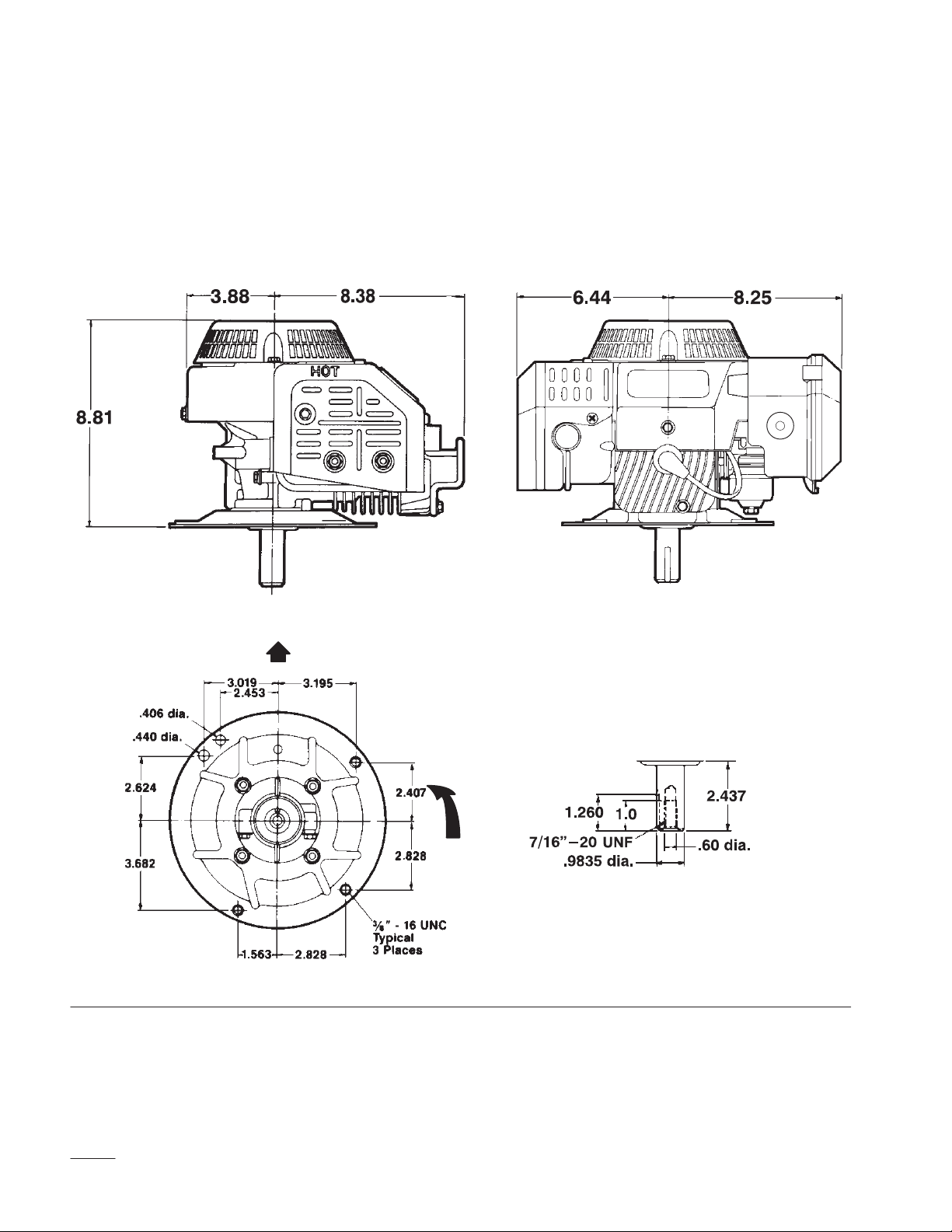
Specifications
Technical Data
(Dimensions in Inches)
*
Front View
Front
*Specifications subject to change without notice.
Rotation
Crankshaft
Figure 1
2
Page 5
Specifications
General Engine Specifications
Engine Type Air-cooled, Two-cycle,. . . . . . . . . . .
3rd Port Induction, Vertical Shaft
Displacement 121 cc. . . . . . . . . . . . . . . . . . . . . . . .
Bore x Stroke 2.283” x 1.811”. . . . . . . . . . . . . . . .
(58 mm x 46 mm)
Ignition System Solid State. . . . . . . . . . . . . . . . . . .
Spark Plug NGK BPMR4A. . . . . . . . . . . . . . . . . .
0.032” (0.8 mm) gap
Governor Mechanical Flyweight. . . . . . . . . . . . . . .
No Load Governor Setting 3000 RPM ± 150. . . .
Main Bearings Ball Bearing. . . . . . . . . . . . . . . . . .
Rod Bearings Caged Needle Bearing. . . . . . . . . . .
Lubrication System Pre-mixed with Fuel. . . . . . .
Air Cleaner Semi-dry, Urethane Foam. . . . . . . . . .
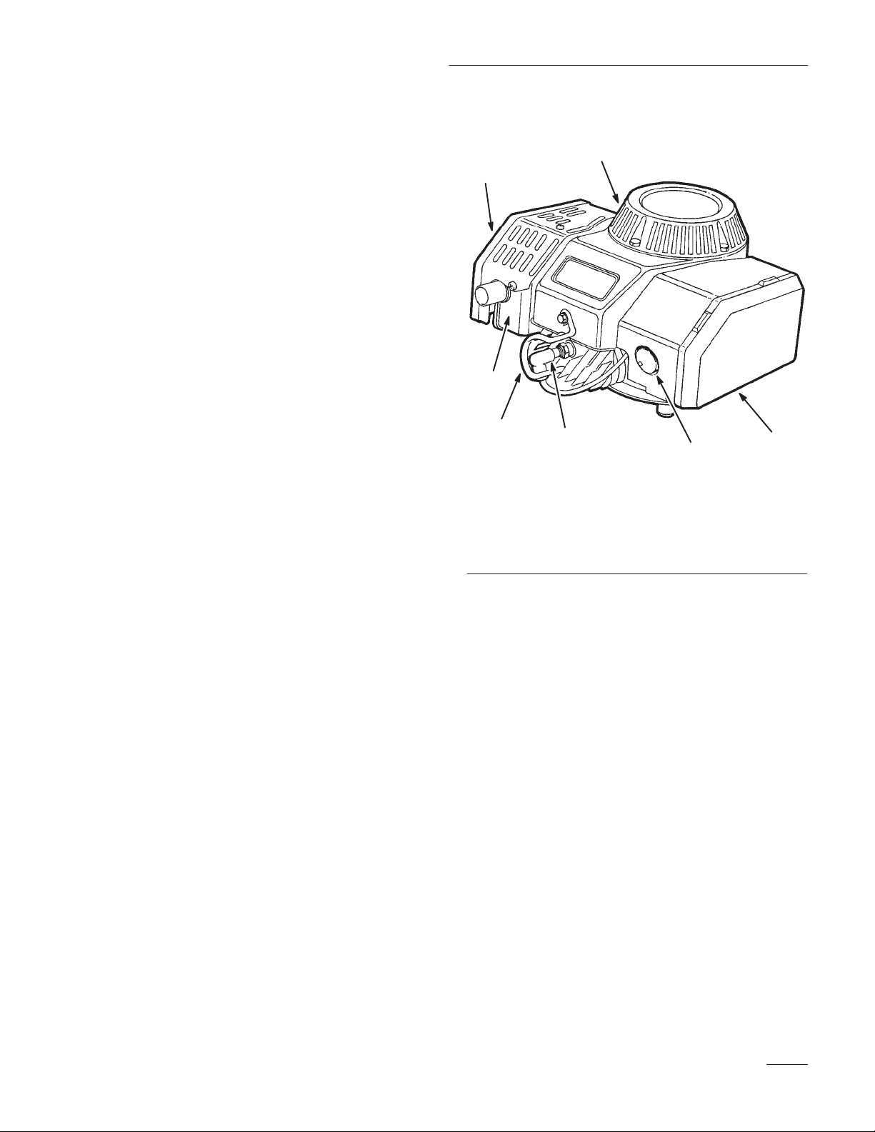
Engine Feature Locations
2
1
3
4
1. Muffler
2. Air Slots in Recoil Housing
3. Muffler Guard Extension
(European requirement
only)
5
6
Figure 2
4. Spark Plug Protector
5. Spark Plug and Wire
6. Primer
7. Air Cleaner
7
Throttle Travel 1.50” (38 mm). . . . . . . . . . . . . . . .
PTO Diameter 1” (25 mm). . . . . . . . . . . . . . . . . . .
PTO Length 2.437” (62 mm). . . . . . . . . . . . . . . . .
Mounting Bolt Size .375” (9.5 mm). . . . . . . . . . .
Direction of Rotation Counterclockwise. . . . . . . .
Dry Weight 20 lbs (9 kg). . . . . . . . . . . . . . . . . . . . .
3
Page 6

Installation
Check the position of the recoil start on the engine
being replaced. Note that this replacement engine is
assembled for zone-start blade applications.
Starter Rope Configuration for
Zone-start Applications
1. Insert the starter rope into the rope guide
(Fig. 3).
1
2
Starter Rope Configuration for
Non-zone-start Applications
1. Remove the recoil assembly (Fig 4).
2. Rotate the recoil assembly 90 degrees clockwise,
then reassemble the recoil assembly to the
engine (Fig 4).
1
m–2705
Figure 3
1. Rope Guide (typical) 2. Starter Rope
2. Fasten the rope stop to the starter rope to within
2-1/2” (64 mm) of the recoil assembly.
Figure 4
1. Recoil Assembly
3. Remove the rope stop and starter handle from
the starter rope.
4. Remove approximately 28” (71 cm) of the starter
rope, then reattach the starter handle.
5. Attach the recoil decal to the recoil assembly so
the decal reads from the front of the engine.
4
Page 7

Installation
Installing the Spark Plug
Protector
Fasten the spark plug protector to the engine using
the self-tapping screws provided with the engine
(Fig 2).
1
2
3
Figure 5
1. Self-tapping Screw (2)
2. Muffler Guard Extension
(European requirement
only)
3. Spark Plug Protector
For European Applications
• A muffler guard extension is attached to the
muffler. This is a European safety requirement
and is not necessary for USA applications
(Fig. 2).
• A fuel decal is provided to be affixed over the
existing fuel decal. USA purchasers may discard
this decal.
Kill Switch Wire
Connect the kill switch wire to the equipment
according to the equipment manufacturer’s
instructions.
Fuel Line
You may have to cut the fuel line to fit your particular
application.
5
Page 8

Operation
Approved Oils and Mixing
Ratios
Your two-cycle engine requires a mixture of gasoline
and oil. Failure to use the correct oils and mixture
will result in serious engine damage.
For simplicity and best engine performance, mix the
contents of one 5.2-ounce bottle of Toro Two-cycle
Oil with two gallons of fresh, unleaded regular
gasoline. Leaded regular gasoline can be used if
unleaded regular is not available.
Toro Two-cycle Oil is specially formulated to
provide superior lubrication, make starting easy and
prolong engine life. Regular use of Toro Two-cycle
Oil will help keep your engine clean, and will help
reduce spark plug fouling, piston ring sticking and
pre-ignition. Toro Two-cycle Oil will also minimize
varnish buildup, combustion chamber deposits and
exhaust port blockage.
You can also use Toro “Easy Mix” Two-cycle Oil
(one 3.2-ounce bottle mixed per gallon of gasoline for
a 40:1 ratio) in this Toro two-cycle engine.
If Toro Two-cycle Oil or Toro “Easy Mix”
Two-cycle Oil is not available, mix two gallons of
gasoline and 5.2 ounces of another high grade
two-cycle oil that has the NMMA or BIA–TCW
certification printed on the label.
Note: Substitute oils may produce more
exhaust smoke, may require increased
engine service (more frequent spark
plug changes and exhaust port/cylinder
decarbonizing), and could reduce
engine life.
IMPORTANT: NEVER USE AUTOMOTIVE
OIL (i.e. SAE 30, 10W30 etc.), OR THE
WRONG MIX RATIO BECAUSE ENGINE
DAMAGE MAY OCCUR. If engine failure
occurs and it has been determined that Toro
Two-cycle Oil was not used, the failure may
not be covered the Toro warranty.
Toro recommends that Toro Stabilizer/Conditioner
be used regularly during operation and storage. Toro
Stabilizer/Conditioner cleans the engine during
operation and prevents gum-like varnish deposits
from forming in the engine during storage.
DO NOT USE FUEL ADDITIVES OTHER
THAN THOSE MANUFACTURED FOR FUEL
STABILIZATION DURING STORAGE, SUCH
AS TORO STABILIZER/CONDITIONER OR A
SIMILAR PRODUCT. TORO’S
STABILIZER/CONDITIONER IS A
PETROLEUM DISTILLATE BASED
CONDITIONER/STABILIZER. TORO DOES
NOT RECOMMEND STABILIZERS WITH AN
ALCOHOL BASE SUCH AS ETHANOL,
METHANOL OR ISOPROPYL. STABILIZERS
SHOULD NOT BE USED TO TRY TO
ENHANCE THE POWER OR PERFORMANCE
OF MACHINE.
6
Page 9

Operation
Mixing Gasoline and Oil
POTENTIAL HAZARD
• In certain conditions gasoline is extremely
flammable and highly explosive.
WHAT CAN HAPPEN
• A fire or explosion from gasoline can burn
you, others, and cause property damage.
HOW TO AVOID THE HAZARD
• Use a funnel and fill the fuel tank outdoors,
in an open area, when the engine is cold.
Wipe up any gasoline that spills.
• Do not fill the fuel tank completely full.
Add gasoline to the fuel tank until the level
is 1/4” to 1/2” (6 mm to 13 mm) below the
bottom of the filler neck. This empty space
in the tank allows gasoline to expand.
• Never smoke when handling gasoline, and
stay away from an open flame or where
gasoline fumes may be ignited by a spark.
• Store gasoline in an approved container
and keep it out of the reach of children.
• Never buy more than a 30-day supply of
gasoline.
Do not use gasoline that has been stored in an
approved container from one season to the next. Use
clean, fresh lead-free gasoline with an octane rating of
85 or higher. Purchase only the quantity of gasoline
that can be used in 30 days to ensure freshness. Use
of lead-free gasoline results in fewer combustion
chamber deposits and longer spark plug life. Leaded
gasoline may be used if lead-free is not available.
Mix the contents of one 5.2-ounce bottle of Toro
Two-cycle Oil with two gallons of fresh, unleaded
regular gasoline as follows:.
1. Pour one gallon of gasoline into an approved
gasoline container, then add one 5.2-ounce bottle
of Toro Two-cycle Oil.
2. Install the cap on the gasoline container and
shake to mix the oil and gasoline thoroughly
(Fig. 6).
3. Slowly remove the cap, then add the remaining
gasoline.
Note: Do not mix gasoline and oil in the
engine fuel tank. Oil that is at room
temperature mixes more easily and
thoroughly than cold oil.
1682
Figure 6
Note: NEVER USE METHANOL,
GASOLINE CONTAINING
METHANOL, GASOHOL
CONTAINING MORE THAN 10%
ETHANOL, PREMIUM GASOLINE
OR WHITE GAS BECAUSE
ENGINE FUEL SYSTEM COULD
BE DAMAGED.
7
Page 10

Operation
Filling the Fuel Tank
1. Pull the spark plug wire off of the spark plug
(Fig. 7).
2. Clean around the fuel cap before removing the
cap.
3. Remove the fuel tank cap and fill the fuel tank
with the gasoline/oil mix to within 1/4 inch
(6 mm) of the top of the tank, not into the filler
neck. DO NOT OVERFILL THE TANK.
4. Reinstall the fuel tank cap securely and wipe up
any spilled fuel.
5. Reconnect the spark plug wire to the spark plug
(Fig. 7).
Starting the Engine
POTENTIAL HAZARD
• Clothing and body parts can get caught in
moving parts on the engine and equipment.
WHAT CAN HAPPEN
• Contact with moving parts on the engine
and equipment could cause serious
personal injury.
HOW TO AVOID THE HAZARD
• Stay away from moving parts on the engine
and equipment.
• Ensure that the equipment is in neutral,
and disengage all clutches, belts and chains.
If the engine is remotely controlled, refer to the
equipment manufacturer’s starting and operating
instructions for control positions which correspond to
the Toro engine’s starting and operating positions.
1
1. Spark Plug Wire
2. Spark Plug
1. Make sure the spark plug wire is connected to
spark plug (Fig. 7).
2. Cover the hole in the center of the primer with
your thumb and push once. An additional prime
may be necessary in extremely cold temperatures
(Fig. 7).
2
3
Note: The choke and primer are usually not
necessary when starting a warm
Figure 7
3. Primer
3. Pull the recoil starter.
engine.
4. To stop the engine, move the remote control on
the equipment to the setting specified by the
equipment manufacturer.
8
Page 11

Maintenance
Service Interval Chart
Each
Service Operation
Service Air Cleaner X
Remove and Check/Replace Spark Plug X
Clean Cooling System X
Clean Muffler Pipe and Exhaust Port X
Drain Gasoline X
Use25Hours75Hours
Storage
Service
Before Performing Any
Maintenance
POTENTIAL HAZARD
• If you leave the wire on the spark plug,
someone could start the engine.
WHAT CAN HAPPEN
• Accidental starting of engine could
seriously injure you or other bystanders.
Stop the engine and pull the spark plug wire off of the
spark plug (Fig. 7).
Notes
Clean more
frequently in
dusty or dirty
conditions
HOW TO AVOID THE HAZARD
• Pull wire off spark plug before performing
any maintenance. Also push wire aside so it
does not accidentally contact spark plug.
1
2
Figure 8
1. Spark Plug 2. Spark Plug Wire
9
Page 12

Maintenance
Servicing the Air Cleaner
Normally clean the air cleaner after every 25
operating hours. More frequent cleaning is required
when the engine is operated in dusty or dirty
conditions.
1. Make sure the spark plug wire is disconnected
from the spark plug (Fig. 9).
3
1
2. Lift the tab at the top of the air cleaner and pivot
the air cleaner cover down. Clean the cover
thoroughly (Fig. 9).
3. If the outside of the foam element is dirty,
remove it from the air cleaner body and clean it
thoroughly as follows:
A. Wash the foam element in a solution of
liquid soap and warm water. Squeeze the
element to remove the dirt.
IMPORTANT: Do not twist the foam element
as the foam may tear.
B. Rinse the element thoroughly in clear water.
C. Dry the element by wrapping it in a clean
rag. Squeeze the rag and element to dry the
element.
D. Saturate the element with engine oil.
Squeeze the element to remove any excess
oil, and to distribute the oil thoroughly. A
damp element is desirable.
2
1. Spark Plug
2. Spark Plug Wire
4
Figure 9
3. Foam Element
4. Air Cleaner Cover
4. Reinstall the foam element and air cleaner cover
(Fig. 9).
IMPORTANT: Do not operate the engine
without the air cleaner element installed or
extreme engine wear and damage will likely
result.
10
Page 13

Maintenance
Replacing the Spark Plug
Use an NGK BPMR4A spark plug or equivalent. The
correct air gap is 0.032” (0.8 mm). Remove the plug
after every 25 operating hours and check its
condition.
1. Stop the engine and pull the spark plug wire off
of the spark plug.
2. Clean around the spark plug and remove the plug
from the cylinder head.
IMPORTANT: Replace a cracked, fouled or
dirty spark plug. Do not sandblast, scrape or
clean the electrodes because engine damage
could result from grit entering the cylinder.
3. Set the air gap to 0.032” (0.8 mm) (Fig. 10).
4. Reinstall the correctly gapped spark plug and
gasket seal. Tighten the plug firmly to 10 ft-lb
(13.6 Nm).
Cleaning the Cooling System
Cleaning the cooling system ensures correct cooling,
best engine performance and maximum engine life.
1. Clean any dirt and chaff from the cylinder,
cylinder head fins, and from around the
carburetor and linkage (Fig. 2).
2. Remove any debris from around the air intake
slots on the recoil housing (Fig. 2).
1
.032”
(0.8 mm)
2
Figure 11
1. Air Slots in Recoil Housing 2. Cylinder Head FIns
986
Figure 10
11
Page 14

Maintenance
Cleaning the Muffler Pipe and
Exhaust Port
POTENTIAL HAZARD
• Muffler and engine surfaces become hot
during operation.
WHAT CAN HAPPEN
• Contact with hot muffler and engine
surfaces could cause a burn.
HOW TO AVOID THE HAZARD
• Clean the muffler and exhaust port only
after the engine and muffler are cool.
Clean the end of the muffler pipe and the exhaust port
every 75 hours of operation.
1. Use a hardwood scraper to remove the carbon
from the end of the muffler pipe (Fig. 12).
3. Remove the hex head screw, then remove the
muffler from the engine (Fig. 12).
4. Make sure the spark plug wire is off of the spark
plug, then slowly pull the starter rope until the
piston covers the exhaust port (Fig. 13).
5. Clean the carbon from the exhaust port with a
flat, hardwood scraper (Fig. 13).
IMPORTANT: Do not use a metal scraper or
similar object to clean the exhaust port. This
can damage the piston or cylinder.
1
2. Remove the Phillips screw, two hex nuts and
lock washers and remove the muffler cover and
attached muffler cover extension from the engine
(Fig. 12).
1
2
Figure 12
1. Hex Head Screw
2. Hex Nut and Lock
Washer (2)
4
3
3. Muffler Cover
4. Muffler Pipe
5. Phillips Screw
3
2
Figure 13
1. Spark Plug
2. Exhaust Port
3. Spark Plug Wire
6. Check the muffler gasket and replace it if worn
5
or damaged.
7. Reinstall the muffler onto the engine, then
reinstall and tighten the hex head screw
(Fig. 12).
8. Reinstall the muffler cover and muffler cover
extension onto the muffler, then reinstall and
tighten the Phillips screw, and the two lock
washers and hex nuts (Fig. 12).
12
Page 15

Maintenance
Draining the Gasoline
POTENTIAL HAZARD
• If gasoline is spilled on a hot engine, it
could ignite.
WHAT CAN HAPPEN
• Contact with burning gasoline could cause
serious personal injury.
HOW TO AVOID THE HAZARD
• Drain gasoline from a cold engine only.
1. Shut off the engine and allow it to cool.
IMPORTANT: Drain gasoline from a cold
engine only.
2. Make sure the spark plug wire is off of the spark
plug. Remove the cap from the fuel tank and use
a pump-type syphon to drain the fuel into a clean
gas can.
Note: This is the only procedure
recommended for draining fuel.
Storage
For long-term storage, either drain the gasoline from
the fuel tank or use a fuel additive before storing. To
drain the gasoline, refer to Draining the Gasoline
above.
If You Leave the Gasoline in the Tank
Fuel can be left in the gas tank only if a fuel additive
such as Toro’s Stabilizer/Conditioner is added to the
gasoline and run through the engine before storing.
Toro’s Stabilizer/Conditioner is a petroleum distillate
based stabilizer/conditioner. Toro does not
recommend stabilizers with an alcohol base such as
ethanol, methanol or isopropyl. Use the fuel additive
in the recommended quantities as specified on the
container. Under normal conditions, fuel additives
remain effective in the fuel for six to eight months.
Coating the Inside of the Cylinder
1. Remove the spark plug and pour two
tablespoons of engine oil into the spark plug
hole in the cylinder.
2. Pull the starter rope slowly to coat the inside of
the cylinder.
3. Reinstall the spark plug and tighten to 10 ft-lbs
(13.6 Nm). DO NOT REINSTALL THE
SPARK PLUG WIRE ONTO THE SPARK
PLUG.
4. Slowly pull the starter rope until resistance is felt
due to compression pressure, then stop. Release
the starter rope tension slowly to prevent the
engine from reversing due to compression
pressure. This position closes both the intake and
exhaust ports to prevent cylinder bore corrosion.
Adjusting the Carburetor
If You Drain the Gasoline
1. After the fuel is drained, start the engine and let
it idle until all the fuel is consumed and the
engine stops.
2. Repeat the starting procedure two more times to
ensure that all the gas is removed from the
engine. If the gasoline is not drained, gum-like
varnish deposits will form and cause poor engine
operation, even starting problems.
The carburetor has been set at the factory and
normally won’t require any further adjustment.
However, when operating the engine at altitudes 5000
feet above sea level and higher, the carburetor jets
may have to be changed. Contact your Authorized
Toro Service Dealer for assistance.
13
Page 16

Walk
Mowers
THE TORO PERFORMANCE
WARRANTY
A Full Warranty
(Limited Warranty for Commercial Use)
What Is Covered By This Express Warranty?
The Toro Company promises to repair any TORO Product
used for normal residential purposes* if defective in materials
or workmanship or if it stops functioning due to the failure of a
component. The following time periods apply from the date of
purchase:
Super Recycler Walk Mowers 5 year full warranty.
All Others 2 year full warranty. . . . . . . . . . . . . . . . . . .
The cost of parts and labor is included, but the customer pays
the transportation costs.
What Products Are Covered By This Warranty?
This warranty applies to all gasoline powered consumer walk
power mowers. Riding products and wide area walk behind
mowers are covered by separate warranty statements.
How About Commercial Use?
TORO Consumer Products used for commercial, institutional
or rental use are warranted against defects in material or
workmanship. Components failing due to normal wear are not
covered by this warranty. The following time periods apply
from the date of purchase:
Products Warranty Period
Engine Entire Unit
21" Commercial Duty
Walk Mowers
With GTS 150 Engine 2 year limited 1 year limited. . . .
Without GTS 150 Engine 1 year limited 1 year limited.
All Others 45 day limited 45 day limited. . . . . . . . . . . . . .
How Do You Get Warranty Service?
Should you feel your TORO Product requires warranty ser
vice, contact the dealer who sold you the product or any Au
thorized TORO Service Dealer or TORO Master Service Deal
er. The Yellow Pages of your telephone directory is a good
reference source. The dealer will either arrange service at
his/her dealership or recommend another Authorized Service
Dealer who may be more convenient. You may need proof of
purchase (copy of registration card, sales receipt, etc.) for
warranty validation.
What Must You Do To Keep The Warranty In Effect?
You must maintain your TORO Product by following the main
tenance procedures described in the operator's manual. Such
routine maintenance, whether performed by a dealer or by
you, is at your expense.
What Does This Warranty Not Cover?
and
How Does Your State Law Relate To This Warranty?
There is no other express warranty except the TORO Starting
Guarantee on GTS Engines. This express warranty does not
cover:
Cost of regular maintenance service or parts, such as filters,
fuel, lubricants, oil changes, spark plugs, blade sharpening,
blade worn out, cable/linkage adjustments or brake and clutch
adjustments.
Any product or part which has been altered or misused or
required replacement or repair due to accidents or lack of
proper maintenance.
Repairs necessary due to improper fuel, contaminants in the
fuel system, or failure to properly prepare the fuel system prior
to any period of non-use over three months.
Pickup and delivery charges.
All repairs covered by this warranty must be performed by an
Authorized TORO Service Dealer using Toro approved replace
ment parts.
Repair by an Authorized TORO Service Dealer is your sole
remedy under this warranty.
The Toro Company is not liable for indirect, incidental or
consequential damages in connection with the use of the
TORO Products covered by this warranty, including any
cost or expense of providing substitute equipment or ser
vice during reasonable periods of malfunction or non-use
pending completion of repairs under this warranty. Some
states do not allow exclusions of incidental or consequen
tial damages, so the above exclusion may not apply to
you.
This warranty gives you specific legal rights, and you may
also have other rights which vary from state to state.
If for any reason you are dissatisfied with the Service Dealer's
analysis of the defect in materials or workmanship or if you
need a referral to a TORO Service Dealer, please feel free to
contact us at the following address:
Toro Customer Service Department
8111 Lyndale Avenue South
Bloomington, MN 55420-1196
612-888-8801
800-348-2424
* Normal residential purposes means mowing the lawn on
the same lot as your home. Use at more than one location
is considered commercial use and the commercial use
warranty would apply.
COUNTRIES OTHER THAN THE UNITED STATES OR CANADA
Customers who have purchased TORO products exported from the United States or Canada should contact their TORO Dis
tributor (Dealer) to obtain guarantee policies for your country, province, or state. If for any reason you are dissatisfied with
your Distributor's service or have difficulty obtaining guarantee information, contact the TORO importer. If all other remedies
fail, you may contact us at The Toro Company.
 Loading...