

Page 1
Recycler Kit
For 52” ProLine and Groundsmaster) Mowers
Model No. 59225
Installation Instructions
Loose Parts
Note: Use the chart below to identify parts used for assembly.
DESCRIPTION QTY. USE
Form No. 3321–650 Rev. A
Kicker
Bolt 5/16–18 x 1”
Spacer
Locknut 5/16-18
Recycler® blade 3 Replace standard blades on mower
Baffle left side
Baffle right side
Bolt 5/16–18 x 5/8”
Washer 5/16”
Locknut 5/16-18
3
3
3
3
1
1
9
3
9
Install kickers
Install Recycler® baffles
Pre–Installation
1. Remove the mower from the traction unit. Refer to the
Mower Operator Manual for instructions.
2. Thoroughly clean the mower. All debris must be
removed to ensure the kickers and baffle will fit tightly
against the mower deck.
3. Repair all bent or damaged areas of mower and
replace any missing parts.
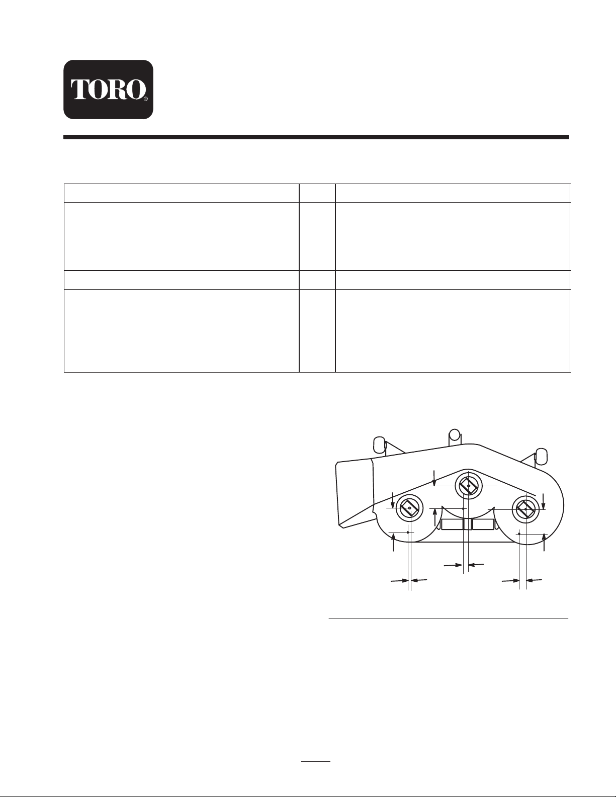
6.81
6.54
5.80
Install Kickers
1. Tip the mower upside down and block up the ends to
ease the installation of the kickers.
2. On Groundsmaster mowers, use the dimensions shown
in figure 1 to locate, mark and drill (3) .344” dia. holes
thru the top of mower deck.
Note: Before drilling the holes, align the kickers with the
hole marks to make sure they fit in the mower deck.
W 1998, 2007 by The Toro Company
8111 Lyndale Avenue South
Bloomington, MN 55420-1196
1.79
.15
Figure 1
All Rights Reserved
1
Printed in the USA
3.43
Page 2
3. Place the spacers and kickers inside the mower deck
.
while aligning the mounting holes (Fig. 2).
4. Secure each kicker to mower deck with a 5/16–18 x 1”
bolt and 5/16-18 locknut (Fig. 2). The bolt heads are to
be positioned inside the mower deck.
2
1
3
1. Alignment pin
2. Baffle kicker (3)
2
1
Figure 4
3. Use one of these holes as
a template to locate hole
in mower housing
Figure 2
1. Kicker 2. Spacer
Installing the Recycler® Baffle
1. On Groundsmaster mowers, use the dimensions shown
in figure 3 to locate, mark and drill (2) .344” dia. holes
thru top of the mower deck.
6.14
11.92
Figure 3
10.08
4.78
4. Align two of the baffle holes with the holes previously
drilled in the mower housing. Make sure there is
clearance between the blades and the baffles.
5. Using the baffles as templates, mark the hole locations
for the remainder of the holes in the mower housing
(Fig. 4). Only drill one additional hole for mounting
the right baffle flange (Fig. 4).
6. Remove the baffles from the mower housing and drill
.344” dia. holes at the marked locations.
7. Secure the baffle flanges together with a 5/16-18 x
5/8” bolt and 5/16” locknut (Fig. 4).
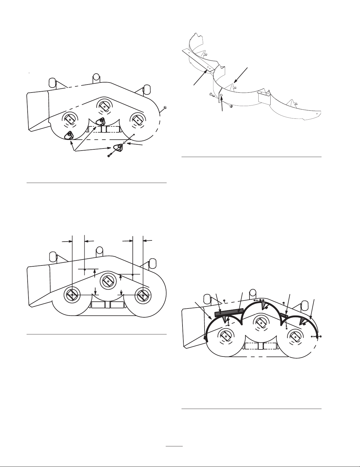
8. Place baffle assembly inside cutting chamber and align
the mounting holes (Fig. 5).
3
3
3
1
2
2. Place the left and right sides of the baffle into the
mower deck.
3. Position the baffle sides together using the alignment
pin on the flanges (Fig. 4).
1. Baffle left side
2. Baffle right side
Figure 5
3. Use the washers at these
locations
2
Page 3

9. Loosely install the baffle flanges to the housing with
(3) 5/16–18 x 5/8” bolts, washers and 5/16-18 locknuts
(Fig. 5). The bolt heads are to be positioned inside the
mower deck and the washers are to positioned next to
the nuts.
10. Loosely install the rest of the baffle to the housing
with (6) 5/16–18 x 5/8” bolts and 5/16-18 locknuts.
The bolt heads are to be positioned inside the mower
deck.
11. Tighten all mounting hardware securely.
3. Install previously removed 5/16–18 x 5/8” (16 mm)
bolts and 5/16-18 locknuts in open holes of mower for
safety (Fig. 7).
3
Install Recycler® Blades
1. Remove standard blades and anti-scalp cups from
spindles.
Note: Save blades and anti-scalp cups for use when side
discharging.
2. Install Recycler® blades in kit. Secure washer and
bolt previously removed (Fig. 6).
3. Rotate blades to assure there is at least 1/8” clearance
between blades and baffle.
2
3
4
5
1. Sail Area of Blade
2. Recycler® blade
3. Anti-scalp cup
Figure 6
4. Washer
5. Blade Bolt
m–1082
2
1
2
3
2
m-2414
Figure 7
1. Baffle left side
2. Bolt 5/16-18 x 5/8”
(16 mm)
3. Locknut 5/16-18
1
POTENTIAL HAZARD
• Open holes in the mower expose you and
others to thrown debris.
WHAT CAN HAPPEN
• Debris thrown out of holes in the mower
can cause injury.
HOW TO AVOID THE HAZARD
• Never operate mower without hardware
mounted in all holes in mower.
• Install hardware in mounting holes when
recycle baffle is removed.
4. Install mower onto traction unit; refer to Installing the
Mower, in Mower Operator’s Manual.
Removing the Recycler®Baffle
1. Thoroughly clean the mower.
2. Remove lock nuts from top and center of right side
baffle (Fig. 7). Lower baffle and slide out of discharge
opening to remove.
Note: Only the right side baffle need be removed for side
discharge mowing.
3
Page 4

 Loading...