

Toro 59187 Operator's Manual
FORM NO. 3319–679
REAR GRASS CATCHER KIT
Contents of Kit
DESCRIPTION QUANTITY
Hanger 1
Hanger Clamp 2
Bag Assy W/Tie Strap 1
Adapter Collar 1
Chute and Support 1
Support – Chute 1
Installing
MODEL NO. 59187
POTENTIAL HAZARD
• If you leave the wire on the spark plug,
someone could start the engine.
WHAT CAN HAPPEN
• Accidental starting of the engine could
seriously injure you or other bystanders.
HOW TO AVOID THE HAZARD
• Stop engine and disconnect spark plug wire
before installing or removing mulch plate.
1. Stop engine and disconnect spark plug wire
before installing or removing cover plate or grass
chute.
INSTALLATION
INSTRUCTIONS
POTENTIAL HAZARD
• Objects could be thrown by mower blade
through an uncovered deck opening or you
could contact rotating blade.
WHAT CAN HAPPEN
• Contact with thrown objects or rotating
blade could cause serious personal injury to
bystanders or operator.
HOW TO AVOID THE HAZARD
• Never operate mower without mulch plate,
grass chute or cover plate covering the
opening in the mower deck
The Toro Company – 1997
All Rights Reserved
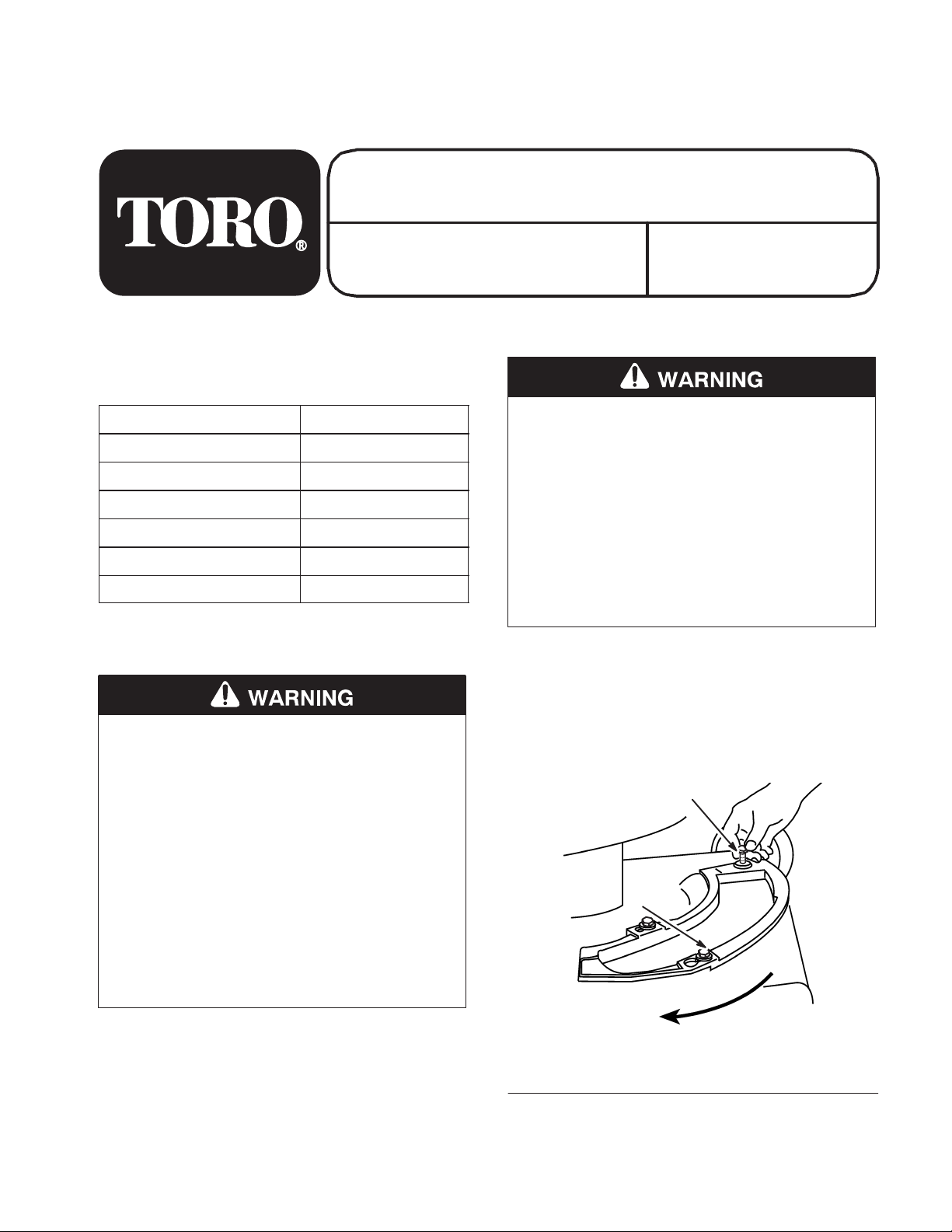
2. Remove screw that fastens cover plate to
housing (Fig. 1).
2
1
m–1754
Figure 1
1. Cover plate 2. Screw
TPS
Installation Instructions
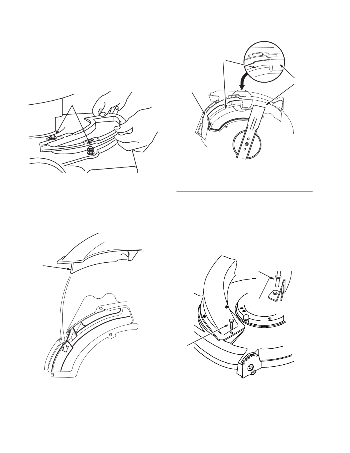
3. Two shoulder bolts on the housing protrude
through slotted holes in the cover plate and do
not have to be loosened or removed (Fig. 2).
Cover plate moves over the shoulder bolt heads.
1
4. Slide cover plate counterclockwise to remove.
1
Figure 2
1. Shoulder bolts
5. Place front corner of chute baffle into deck
opening. Rotate chute counterclockwise and
push down into deck opening (Fig. 3 & 4).
995
2
3
Figure 4
1. Chute baffle
2. Front deck baffle
3. T oe guard
Note: The chute baffle must go behind the
front deck baffle and between blade
and toe guard to prevent contact with
blade.
6. Insert chute support rod through hole in right
side of deck bracket (Fig. 5).
m-1129
1
1. Chute baffle
Figure 3
m-1073
1
2
m-1013/2035
Figure 5
1. Chute support rod 2. Screw
EN-2
Installation Instructions
7. Two shoulder bolts on the mower housing
protrude through slotted holes in the chute
assembly and do not have to be loosened or
removed. Chute assembly moves over the
shoulder bolts (Fig. 5).
8. Slide chute assembly in a clockwise direction to
install or counterclockwise to remove.
9. Secure with screw (Fig. 5).
10. To ensure the chute was installed properly, rotate
blade a few revolutions by pulling slowly on
starter cord or look under deck to see if blade
contacts chute baffle.
POTENTIAL HAZARD
• A non-Toro replacement cutting blade
could strike chute baffle when engine is
started and run.
12. Hold hanger clamp on outside of handle
sections. Insert handle bolt from inside of handle
sections through holes in hanger clamp.
13. Position bag hanger leg into hanger clamp
groove and secure with knob. Repeat steps and
assemble clamp and hanger to right side handle
sections.
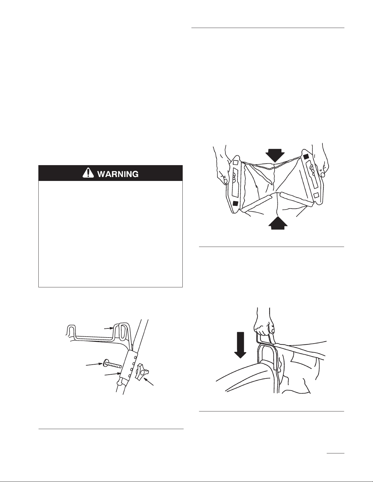
14. Close rear of bag by folding sides in and
pressing interlocking rear handle halves together
(Fig. 7).
WHAT CAN HAPPEN
• Blade contact with chute baffle will cause
damage which could result in an unsafe
operating condition or thrown objects.
HOW TO AVOID THE HAZARD
• Use only Toro original equipment or Toro
replacement cutting blade.
11. Remove knob and bolt securing left side upper
and lower handle sections (Fig. 6).
4
2
3
1
Figure 6
1. Knob
2. Bolt
3. Hanger clamp
4. Bag hanger
1012
Figure 7
15. Position rear bag handles into bag hanger on
handle.
16. Grasp bag assembly handle and slide over flange
of grass chute (Fig. 8). Push downward on
handle until it seats into position.
1011
1010
Figure 8
17. Reconnect spark plug wire.
EN-3
Installation Instructions
Bag Adjustment
When handle height is changed bag adjustment may
be required. A properly adjusted bag should be taut
on top cloth area between front bag handle and rear
bag hanger handles. If bag is too tight or too loose,
adjust as follows:
1. Stop engine and disconnect spark plug wire.
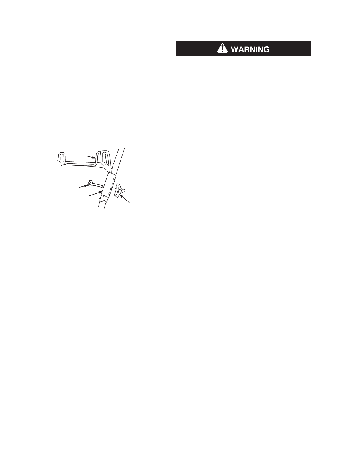
2. Remove bag from rear bag hanger. Remove
bolt(s) and knob(s) securing hanger clamps to
handle sections (Fig. 9). Hanger clamps have
four adjustment holes.
4
POTENTIAL HAZARD
• Keep hands, sticks or other objects out of
grass chute while blade is turning.
WHAT CAN HAPPEN
• Thrown objects or blade contact can cause
serious injury.
HOW TO AVOID THE HAZARD
• Always stop engine when emptying grass
bag and disconnect spark plug wire before
cleaning a clogged chute, bag tunnel or
underside of mower housing.
4. Reconnect spark plug wire.
2
3
1
Figure 9
1. Knob
2. Bolt
3. Hanger clamp
4. Bag hanger
3. Reassemble hanger clamps to handle sections
using whichever set of holes best holds bag taut.
Using lower holes in hanger clamps tightens bag
assembly and upper holes in hanger clamps
loosens bag assembly.
Note: Under normal use, bag materials are
subject to deterioration and wear.
Check grass bag often and replace
when necessary with an original
equipment replacement bag. A
weakened or inferior bag may let
objects pass through, causing injury.
1011
EN-4

DOC. NO. 3319–679
KIT DE SAC À HERBE ARRIÈRE
Composition du kit
Description Quantité
Porte-sac 1
Bride du porte-sac 2
Sac avec sangle de fixation 1
Collier adaptateur 1
Chute et support 1
Support – Chute 1
Installation
MODÈLE NO. 59187
DANGER POTENTIEL
• Si les ouvertures du carter ne sont pas
obturées, la lame est exposée et risque de
blesser quelqu’un et de projeter des objets.
QUELS SONT LES RISQUES?
• Les objets projetés ou le contact avec la
lame en rotation peuvent causer des
blessures graves à l’opérateur ou aux
personnes se tenant à proximité.
COMMENT SE PROTÉGER?
• Ne jamais utiliser la tondeuse si la plaque
de paillage, la chute d’éjection d’herbe ou
l’obturateur ne sont pas installés.
INSTRUCTIONS
DE MONTAGE
DANGER POTENTIEL
• Si le fil de bougie n’est pas débranché,
quelqu’un risque de faire démarrer la
tondeuse accidentellement.
QUELS SONT LES RISQUES?
• Le démarrage accidentel peut causer des
blessures graves à l’opérateur et aux
personnes se tenant à proximité.
COMMENT SE PROTÉGER?
• Avant d’installer ou de retirer la plaque de
paillage, arrêter le moteur et débrancher le
fil de la bougie.
The Toro Company – 1997
Tous droits réservés
1. Avant d’installer ou de retirer l’obturateur ou la
chute d’éjection d’herbe, arrêter le moteur et
débrancher le fil de la bougie.
2. Retirer la vis fixant l’obturateur au carter de la
tondeuse (Fig. 1).
 Loading...