

Page 1
Part No. 08159SL
Service Manual
Groundsmaster
Preface
The purposeof this publication is to provide theservice
technician with information for troubleshooting, testing,
and repair of major systems and components on the
Groundsmaster 5900 and 5910.
REFER TO THE OPERATOR’S MANUALS FOR OPERATING, MAINTENANCE AND ADJUSTMENT
INSTRUCTIONS. For reference, insert a copy of the
Operator’s Manual and Parts Catalog for yourmachine
into Chapter 2 of this service manual. Additional copies
of the Operator’s Manual and Parts Catalog are available on the internet at www.Toro.com.
TheToroCompanyreserves the right to changeproduct
specifications or this publication without notice.
R
5900 & 5910
This safety symbol means DANGER, WARNING,
or CAUTION, PERSONAL SAFETY INSTRUCTION. When you see this symbol, carefully read
the instructions that follow. Failure to obey the
instructions may result in personal injury.
NOTE: ANOTE willgive generalinformation aboutthe
correct operation, maintenance, service, testing or repair of the machine.
IMPORTANT: The IMPORTANT notice will give importantinstructionswhichmust befollowedto prevent damage to systems or components on the
machine.
E The Toro Company -- 2009
Page 2

This page is intentionally blank.
Groundsmaster 5900/5910
Page 3

Table Of Contents
Chapter 1 -- Safety
General Safety Instructions 1 -- 2..................
Jacking Instructions 1 -- 5.........................
Safety and Instruction Decals 1 -- 6................
Chapter 2 -- Product Records and Maintenance
Product Records 2 -- 1...........................
Maintenance 2 -- 1...............................
Equivalents and Conversions 2 -- 2................
Torque Specifications 2 -- 3.......................
Chapter 3 -- Diesel Engine
General Information 3 -- 2........................
Engine Specifications 3 -- 4.......................
Engine Fastener Torque Specifications 3 -- 5........
Adjustments 3 -- 7...............................
Service and Repairs 3 -- 8........................
Chapter 4 -- Hydraulic System
Specifications 4 -- 2..............................
General Information 4 -- 3........................
Hydraulic Schematic 4 -- 11.......................
Hydraulic Flow Diagrams 4 -- 12...................
Special Tools 4 -- 30.............................
Troubleshooting 4 -- 33...........................
Testing 4 - - 38...................................
Adjustments 4 -- 60..............................
Service and Repairs 4 -- 61.......................
SAUERDANFOSSDSERIESGEARPUMPSEALKIT
SERVICE INSTRUCTION BULLETIN
REXROTH VARIABLE PUMP A10VG REPAIR IN-
STRUCTIONS
REXROTHVARIABLEPUMPA10VG REPAIRMANU-
AL
EATON REPAIR INFORMATION: MODEL 74318 and
74348 PISTON MOTORS
PARKER TORQMOTOR
(TC, TB, TE, TJ, TF, TG, TH AND TL SERIES)
EATON PARTS AND REPAIR INFORMATION: 5
SERIES STEERING CONTROL UNITS
TM
SERVICE PROCEDURE
Chapter 5 -- Electrical System
General Information 5 -- 2........................
Electrical Drawings 5 -- 3.........................
Special Tools 5 -- 4..............................
Troubleshooting 5 -- 6............................
Info Center Display 5 -- 11........................
Electrical System Quick Checks 5 -- 28.............
Adjustments 5 -- 30..............................
Component Testing 5 -- 32........................
Service and Repairs 5 -- 63.......................
Chapter 6 -- Axles, Planetaries and Brakes
Specifications 6 -- 2..............................
General Information 6 -- 3........................
Service and Repairs 6 -- 4........................
Chapter 7 -- Chassis
General Information 7 -- 1........................
Service and Repairs 7 -- 2........................
Chapter 8 -- Cutting Decks
Specifications 8 -- 2..............................
Troubleshooting 8 -- 3............................
General Information 8 -- 4........................
Service and Repairs 8 -- 6........................
SafetyProduct Records
Diesel
Hydraulic
Electrical
Axles, Planetaries
and Maintenance
Engine
System
System
and Brakes
Groundsmaster 5900/5910
Cutting Decks Chassis
Page 4

This page is intentionally blank.
Groundsmaster 5900/5910
Page 5

Table Of Contents (Continued)
Chapter 9 -- Operator Cab
General Information 9 -- 2........................
Service and Repairs 9 -- 3........................
ICE COMPRESSOR SERVICE MANUAL
Chapter 10 -- Foldout Drawings
Hydraulic Schematic 10 -- 3.......................
Electrical Schematics 10 -- 4......................
Wire Harness Drawings 10 -- 10..................
Cab
OperatorFoldout
Drawings
Groundsmaster 5900/5910
Page 6

This page is intentionally blank.
Groundsmaster 5900/5910
Page 7

Chapter 1
Table of Contents
GENERAL SAFETY INSTRUCTIONS 2............
Before Operating 2............................
While Operating 3.............................
Maintenance and Service 4....................
JACKING INSTRUCTIONS 5.....................
Jacking the Front End 5........................
Jacking the Rear End 5........................
SAFETY AND INSTRUCTION DECALS 6..........
Safety
Safety
Groundsmaster 5900/5910 Page 1 -- 1 Safety
Page 8

General Safety Instructions
TheGroundsmaster 5900 and 5910 are testedand certified by Toro for compliance with existing safety standards and specifications. Although hazard control and
accident prevention partially are dependent upon the
design and configuration of the machine, these factors
are also dependent upon the awareness, concern and
proper training of the personnel involved in the operation, transport, maintenance and storage of the machine.Improperuseormaintenance of themachinecan
resultininjuryordeath. Toreduce the potentialforinjury
or death, comply with the following safety instructions.
Before Operating
WARNING
To reduce the potential for injury or death,
comply with the following safety instructions.
1. Review and understand the contents of the Operator’s Manual and Operator’s DVD before starting and
operating the machine. Become familiar with the controls and know how to stop the machine and engine
quickly. Additionalcopies ofthe Operator’s Manual are
available on the internet at www.Toro.com.
2. Keep all shields, safetydevicesanddecals in place.
Ifashield,safetydeviceordecalisdefective,illegibleor
damaged, repair or replace it before operating the machine.Alsotightenany loose nuts,boltsorscrewstoensure machine is in safe operating condition.
3. Assure interlock switches are adjusted correctly so
engine cannot be started unless traction pedal is in
NEUTRAL and PTO switch is OFF (disengaged).
4. Since diesel fuel is flammable, handle it carefully:
A. Use an approved fuel container.
B. Donotremove fueltankcapwhile engineishotor
running.
C. Do not smoke while handling fuel.
D. Fillfueltankoutdoorsandonly towithinaninchof
the top of the tank, not the filler neck.Do notoverfill
fuel tank.
E. Wipe up any spilled fuel.
Groundsmaster 5900/5910Page 1 -- 2Safety
Page 9

While Operating
1. Sit onthe seatwhen starting and operating the machine.
2. Before starting the engine:
A. Engage the parking brake.
B. Makesurethetractionpedalis intheneutralposi-
tion and the PTO switch is OFF (disengaged).
C. Afterengineisstarted, releaseparkingbrakeand
keepfootofftractionpedal.Machinemustnot move.
Ifmovementisevident,the traction pedal isadjusted
incorrectly;therefore,shutengineoffandadjusttraction system until machinedoesnotmove when traction pedal is released.
3. Do not run engine in a confined area without ade-
quate ventilation. Exhaust fumes are hazardous and
could possibly be deadly.
4. Do not touch engine, radiator or exhaust system
whileengineis runningorsoonafteritis stopped.These
areas could be hot enough to cause burns.
5. Before getting off the seat:
A. Ensure that traction pedal is in the neutral posi-
tion.
B. Apply parking brake.
C. Lower the cutting decks fully to the ground. This
relieves pressure from the lift circuit and eliminates
the risk of the cutting decks accidentallylowering to
the ground.
D. Disengage cutting decks and wait for cutting
blades to stop completely.
E. Allow engineto run at low idle speed for at least
five (5)minutes after full load operation to allow the
turbocharger to cool.
F. Stopengineandremovekeyfromswitch.Waitfor
all machine movement to stop.
6. Do not park machine on slopes unless wheels are
chocked or blocked.
Safety
Groundsmaster 5900/5910 Page 1 -- 3 Safety
Page 10

Maintenance and Service
1. Before servicing or making machine adjustments,
lower cutting decks, stop engine, apply parking brake
and remove key from the ignition switch.
2. Make sure machine isinsafeoperating condition by
keeping all nuts, bolts and screws tight.
3. Shut engine off before checking or adding oil to the
engine crankcase.
4. To reduce potential fire hazard, keep engine area
free of excessive grease, grass, leaves and dirt.Clean
protective screen on machine frequently.
5. Never store the machine or fuel container inside
wherethereisanopenflame,suchasnearawaterheater or furnace.
6. Do not overspeed the engineby changing governor
setting.Toassuresafetyandaccuracy,checkmaximum
engine speed.
7. Disconnect batteries before servicing the machine.
Disconnect negative battery cables first and positive
cables last. If battery voltage is required for troubleshooting or test procedures, temporarily connect the
batteries. Reconnect positive battery cables first and
negative cables last.
8. Battery acid is poisonous and can cause burns.
Avoidcontact with skin,eyesand clothing. Protect your
face, eyes and clothing when working with a battery.
9. Battery gases canexplode. Keep cigarettes,sparks
and flames away from the battery.
10.When changing attachments, tires or performing
otherservicethatrequiresthemachine toberaised,use
correct jacks, hoists and supports.Make suremachine
is parked on a solid level surface such as a concrete
floor. Prior to raising the machine, remove any attachmentsthatmayinterferewiththe safeandproperraising
ofthemachine.Always chockorblockwheels.Uses uitable jack stands to support the raised machine. If the
machine is not properly supported by jack stands, the
machinemay move or fall,which mayresultinpersonal
injury (see Jacking Instructions in this chapter).
11.Make sureallhydrauliclineconnectorsare tight,and
all hydraulic hoses and lines are in good condition before applying pressure to the system.
12.Keepbodyandhandsawayfrompinholeleaksinhydrauliclinesthatejecthighpressurehydraulic fluid. Use
cardboard or paper to find hydraulic leaks. Hydraulic
fluid escaping under pressure can penetrate skin and
cause injury. Fluid accidentally injected into the skin
mustbesurgicallyremovedwithinafewhoursby a doctor familiar with this form of injury or gangrene may result.
13.Before disconnectingorperforming any work onthe
hydraulic system, all pressure in system must be relieved by stopping engine and lowering the cutting
decks to the ground.
14.Make sure all engine fuel system connectors and
components are correctly installed, and all fuel hoses
are in good condition before starting engine.
15.Keep bodyandhandsawayfrom leaksinenginefuel
injectionlines.Usecardboard or papertofindhighpressurefuelleaksiftheymayexist.Leakingfuelunderpressure can penetrate skin and cause injury.
16.If enginemustberunningtoperformmaintenance or
an adjustment, keep hands, feet, clothing and other
parts of the body away from cutting decks and other
moving parts. Keep bystanders away.
17.At the time ofmanufacture, the machine conformed
tothesafetystandardsfor riding mowers. Toassureoptimumperformanceandcontinued safety certificationof
the machine, use genuine Toro replacement parts and
accessories.Replacementpartsandaccessoriesmade
by other manufacturers mayresultin non-conformance
with the safety standards, and the warranty may be
voided.
18.When welding on machine, disconnect all battery
cables to preventdamageto machine electronicequipment. Disconnect negative battery cable first and positive cable last. Disconnect and remove engine
electronic control module (ECM) from engine before
welding on the machine. Also, attach welder ground
cable no more than two (2) feet (0.61 meters) from the
welding location.
19.If major repairsareeverneededor assistance is desired, contact an Authorized Toro Distributor.
Groundsmaster 5900/5910Page 1 -- 4Safety
Page 11

Jacking Instructions
CAUTION
When changing attachments, tires or performingotherservice thatrequiresthemachine tobe
raised,usecorrect jacks,hoistsandsupportsto
raise and support the machine. Make sure machineisparkedonasolid levelsurfacesuch asa
concretefloor.Prior to raising machine, remove
anyattachmentsthatmay interfere with thesafe
and proper raising of the machine. Always
chock or block wheels. Use appropriate jack
stands to support the raised machine. Ifthemachine is not properly supportedby jack stands,
the machine may moveor fall, which may result
in personal injury.
Jacking the Front End (Fig. 1)
1. Chock both rear tires to prevent the machine from
moving.
2. Position jack securely under the frame, just to the inside ofthe fronttire. Makesure thatjack does not contact hydraulic lift cylinder.
3. Position appropriate jackstands under theframeas
close to the front wheel as possible to support the machine.
Jacking the Rear End (Fig. 2)
2
Figure 1
1. Frame jacking point 2. Front tire
2
Figure 2
1. Rear axle jacking point 2. Rear tire
1
Safety
1
2
1. Applyparkingbrakeandchockbothfronttires toprevent the machine from moving.
2. Place jack securely under the center of rear axle.
Jack rear of machine off the ground.
3. Use appropriate jack stands under the rear axle to
support the machine.
Groundsmaster 5900/5910 Page 1 -- 5 Safety
Page 12

Safety and Instruction Decals
Numerous safety and instruction decals are affixed to
your Groundsmaster. If any decal becomes illegible or
damaged, install a new decal. Decal part numbers are
listed in your Parts Catalog.
Groundsmaster 5900/5910Page 1 -- 6Safety
Page 13

Product Records and Maintenance
Table of Contents
Chapter 2
PRODUCT RECORDS 1.........................
MAINTENANCE 1...............................
EQUIVALENTS AND CONVERSIONS 2...........
Decimal and Millimeter Equivalents 2............
U.S. to Metric Conversions 2...................
TORQUE SPECIFICATIONS 3....................
Fastener Identification 3.......................
Product Records
Insert Operator’s Manuals and Parts Catalogs for your
Groundsmaster at the end of this chapter. Additionally,
if any optional equipment or accessories have been
installedto your machine, inserttheInstallationInstructions, Operator’s Manuals andPartsCatalogs for those
options at the end of this chapter.
Maintenance
Maintenanceproceduresand recommended serviceintervalsforyourGroundsmasterarecoveredintheOperator’s Manuals. Refer to this publication when
performing regular equipment maintenance.
Standard Torque for Dry, Zinc Plated, and
Steel Fasteners (Inch Series) 4...............
Standard Torque for Dry, Zinc Plated, and
Steel Fasteners (Metric) 5....................
Other Torque Specifications 6..................
Conversion Factors 6..........................
Product Records
and Maintenance
Groundsmaster 5900/5910 Page 2 -- 1 Product Records and Maintenance
Page 14
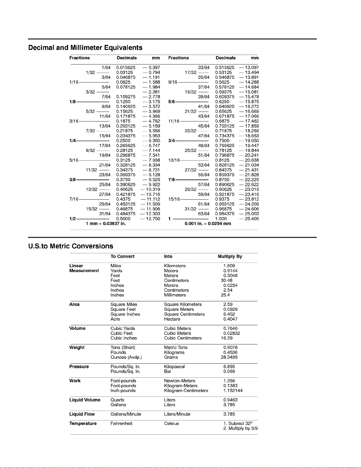
Equivalents and Conversions
0.09375
Groundsmaster 5900/5910Page 2 -- 2Product Records and Maintenance
Page 15
Torque Specifications
Recommended fastener torque values are listed in the
followingtables.Forcriticalapplications,asdetermined
byToro, eithertherecommendedtorqueora torque that
is unique to theapplicationis clearly identifiedandspecified in this Service Manual.
These Torque Specifications for the installation and
tightening of fasteners shallapply to all fastenerswhich
donot have a specific requirement identified inthis Service Manual. The following factors shall be considered
when applying torque: cleanliness of the fastener, use
of a thread sealant (e.g. Loctite), degree of lubrication
on the fastener, presenceof a prevailingtorque feature
(e.g. Nylock nut), hardness of the surface underneath
thefastener’sheadorsimilarconditionwhichaffectsthe
installation.
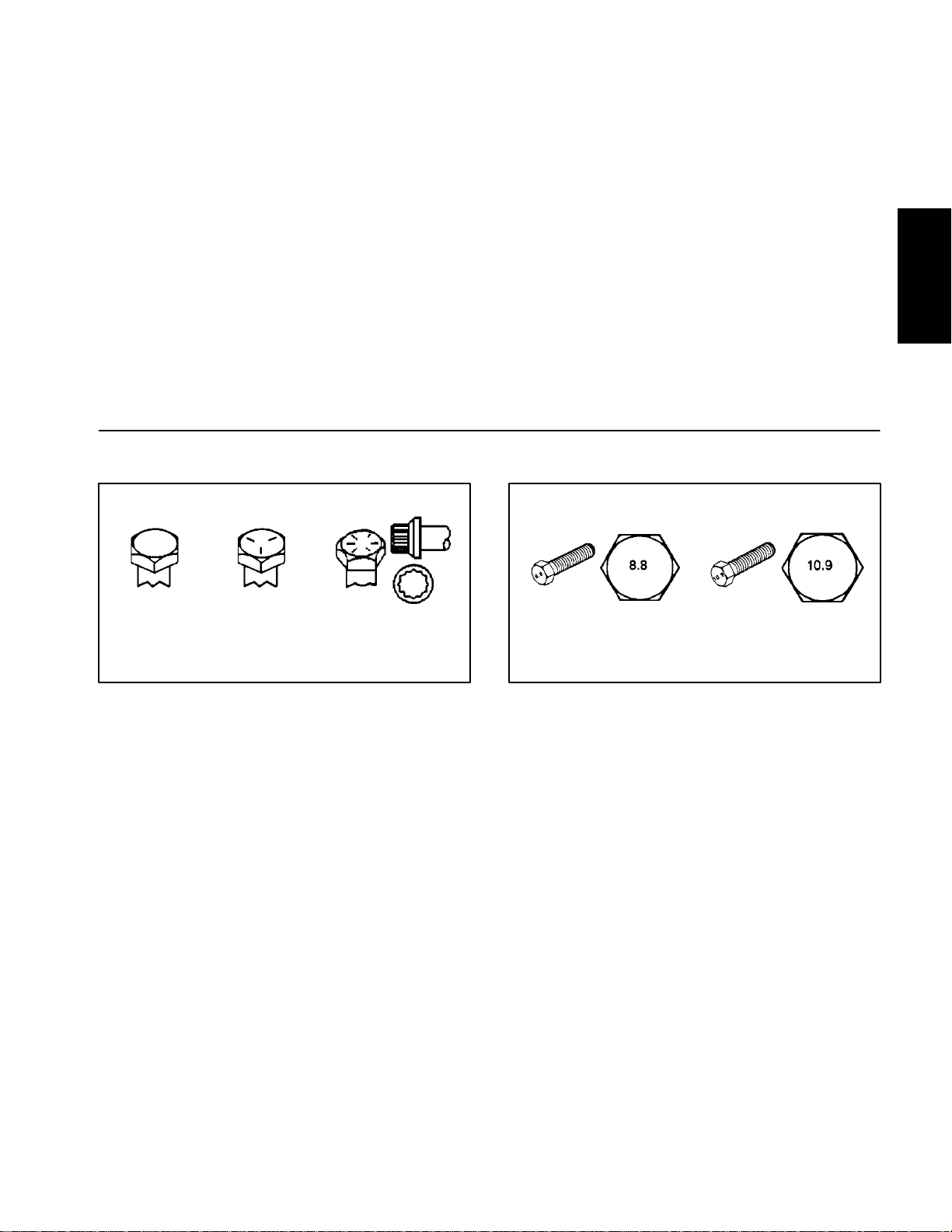
Fastener Identification
Asnotedin thefollowingtables,torque valuesshouldbe
reduced by 25% for lubricated fasteners to achieve
the similar stress as a dry fastener. Torquevalues may
also have to be reduced when the fastener is threaded
into aluminum or brass. The specific torque value
should be determined based onthe aluminum or brass
material strength, fastener size, length of thread engagement, etc.
The standard method of verifying torque shall be performed by marking a line on the fastener (head or nut)
and mating part, then back off fastener 1/4 of a turn.
Measurethetorquerequiredtotightenthefastener until
the lines match up.
Product Records
and Maintenance
Grade 1 Grade 5 Grade 8
Inch Series Bolts and Screws
Figure 1
Class 8.8 Class 10.9
Metric Bolts and Screws
Figure 2
Groundsmaster 5900/5910 Page 2 -- 3 Product Records and Maintenance
Page 16
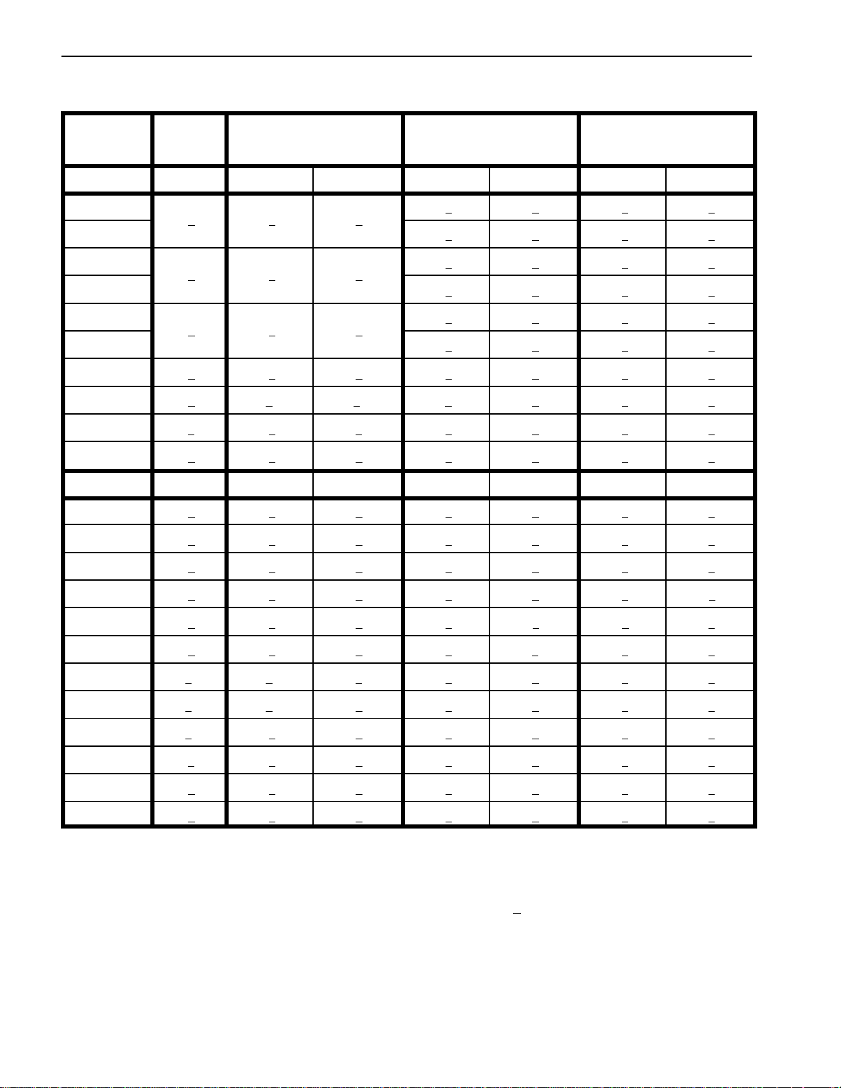
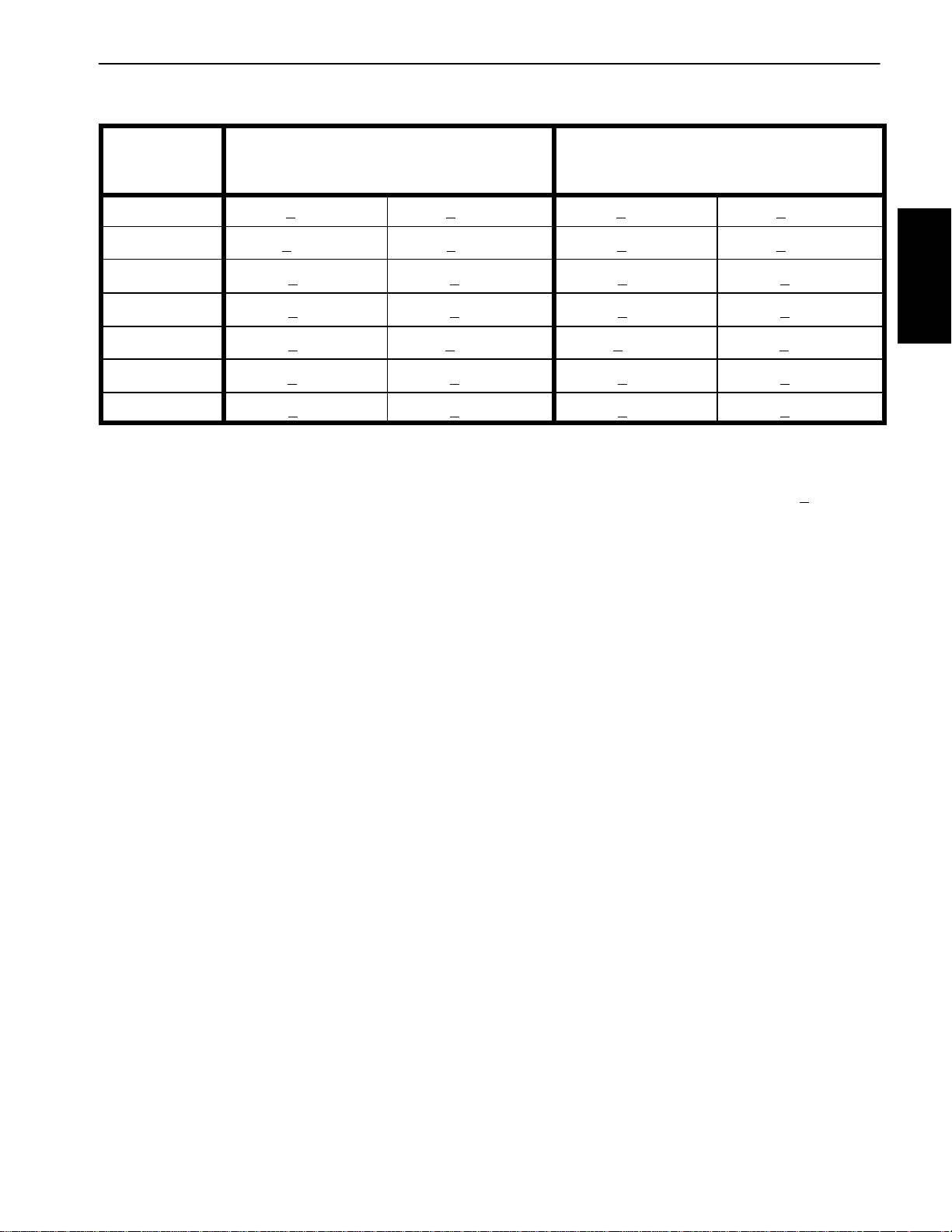
Standard Torque for Dry, Zinc Plated and Steel Fasteners (Inch Series)
Thread Size
# 6 -- 32 UNC
# 6 -- 40 UNF
# 8 -- 32 UNC
# 8 -- 36 UNF
#10--24UNC
#10--32UNF
1/4 -- 20 UNC 48 + 7 53 + 7 599 + 79 100 + 10 1130 + 113 140 + 15 1582 + 169
1/4 -- 28 UNF 53 + 7 65 + 10 734 + 113 115 + 12 1299 + 136 160 + 17 1808 + 192
5/16 -- 18 UNC 115 + 15 105 + 15 1186 + 169 200 + 25 2260 + 282 300 + 30 3390 + 339
5/16 -- 24 UNF 138 + 17 128 + 17 1446 + 192 225 + 25 2542 + 282 325 + 33 3672 + 373
3/8 -- 16 UNC 16 + 2 16 + 2 22+ 3 30 + 3 41 + 4 43 + 5 58 + 7
Grade 1, 5 &
8withThin
Height Nuts
in--lb in--lb N--cm in--lb N--cm in--lb N--cm
10 + 2 13 + 2 147 + 23
13 + 2 25 + 5 282 + 56
18 + 2 30 + 5 339 + 56
ft--lb ft--lb N--m ft--lb N--m ft--lb N--m
SAE Grade 1 Bolts, Screws, Studs &
Sems with Regular Height Nuts
(SAE J995 Grade 2 or Stronger Nuts)
SAE Grade 5 Bolts, Screws, Studs &
Sems with Regular Height Nuts
(SAE J995 Grade 2 or Stronger Nuts)
15 + 2 169 + 23 23 + 3 262 + 34
17 + 2 192 + 23 25 + 3 282 + 34
29 + 3 328 + 34 41 + 5 463 + 56
31 + 4 350 + 45 43 + 5 486 + 56
42 + 5 475 + 56 60 + 6 678 + 68
48 + 5 542 + 56 68 + 7 768 + 79
SAE Grade 8 Bolts, Screws, Studs &
Sems with Regular Height Nuts
(SAE J995 Grade 5 or Stronger Nuts)
3/8 -- 24 UNF 17 + 2 18 +2 24 +3 35 + 4 47 + 5 50 + 6 68 + 8
7/16 -- 14 UNC 27 + 3 27 + 3 37 + 4 50 + 5 68 + 7 70 +7 95 +9
7/16 -- 20 UNF 29 +3 29 + 3 39 + 4 55 + 6 75 + 8 77 +8 104 + 11
1/2 -- 13 UNC 30 + 3 48 + 7 65 + 9 75 + 8 102 +11 105 + 11 142 + 15
1/2 -- 20 UNF 32 + 4 53 +7 72 +9 85 + 9 115 + 12 120 + 12 163 + 16
5/8 -- 11 UNC 65 + 10 88 + 12 119 + 16 150 + 15 203 + 20 210 + 21 285 + 28
5/8 -- 18 UNF 75 +10 95 + 15 129 + 20 170 + 18 230 + 24 240 +24 325 + 33
3/4 -- 10 UNC 93 + 12 140 + 20 190 + 27 265 + 27 359 +37 375 + 38 508 + 52
3/4 -- 16 UNF 115 + 15 165 + 25 224 + 34 300 + 30 407 + 41 420 +43 569 + 58
7/8 -- 9 UNC 140 + 20 225 + 25 305 + 34 430 + 45 583 + 61 600 + 60 813 + 81
7/8 -- 14 UNF 155 + 25 260 + 30 353 + 41 475 + 48 644 + 65 667 + 66 904 + 89
NOTE: Reduce torque values listed inthe tableabove
by 25% for lubricated fasteners. Lubricated fasteners
are defined as threads coated with a lubricant such as
engine oil or thread sealant such as Loctite.
NOTE: The nominal torque values listed above for
Grade 5 and8 fasteners arebased on 75%of the minimumproofload specified in SAE J429. The toleranceis
approximately +
10% of the nominal torquevalue. Thin
height nuts include jam nuts.
NOTE: Torque values may have to be reduced when
installing fasteners into threaded aluminum or brass.
The specifictorque value should be determined based
on the fastener size, the aluminum or base material
strength, length of thread engagement, etc.
Groundsmaster 5900/5910Page 2 -- 4Product Records and Maintenance
Page 17
Standard Torque for Dry, Zinc Plated and Steel Fasteners (Metric Series)
Class 8.8 Bolts, Screws and Studs with
Thread Size Regular Height Nuts
(Class 8 or Stronger Nuts)
M5 X 0.8 57 + 6in--lb 644 + 68 N--cm 78 + 8in--lb 881 + 90 N--cm
M6 X 1.0 96 + 10 in--lb 1085 + 113 N- -cm 133 + 14 in--lb 1503 + 158 N--cm
M8 X 1.25 19 + 2ft--lb 26 + 3N--m 28 + 3ft--lb 38 + 4N--m
M10 X 1.5 38 + 4ft--lb 52 + 5N--m 54 + 6ft--lb 73 + 8N--m
M12 X 1.75 66 + 7ft--lb 90 + 10 N--m 93+ 10 ft--lb 126 + 14 N--m
M16 X 2.0 166 + 17 ft--lb 225 + 23 N--m 229 + 23 ft--lb 310 + 31 N--m
M20 X 2.5 325 + 33 ft--lb 440 + 45 N--m 450 + 46 ft--lb 610 + 62 N--m
NOTE: Reduce torque values listed inthe tableabove
by 25% for lubricated fasteners. Lubricated fasteners
are defined as threads coated with a lubricant such as
engine oil or thread sealant such as Loctite.
NOTE: Torque values may have to be reduced when
installing fasteners into threaded aluminum or brass.
The specifictorque value should be determined based
on the fastener size, the aluminum or base material
strength, length of thread engagement, etc.
NOTE: The nominal torque values listed above are
based on 75% of the minimum proof load specified in
SAEJ1199.Thetoleranceis approximately+
nominal torque value.
Class 10.9 Bolts, Screws and Studs with
Regular Height Nuts
(Class 10 or Stronger Nuts)
10%ofthe
Product Records
and Maintenance
Groundsmaster 5900/5910 Page 2 -- 5 Product Records and Maintenance
Page 18
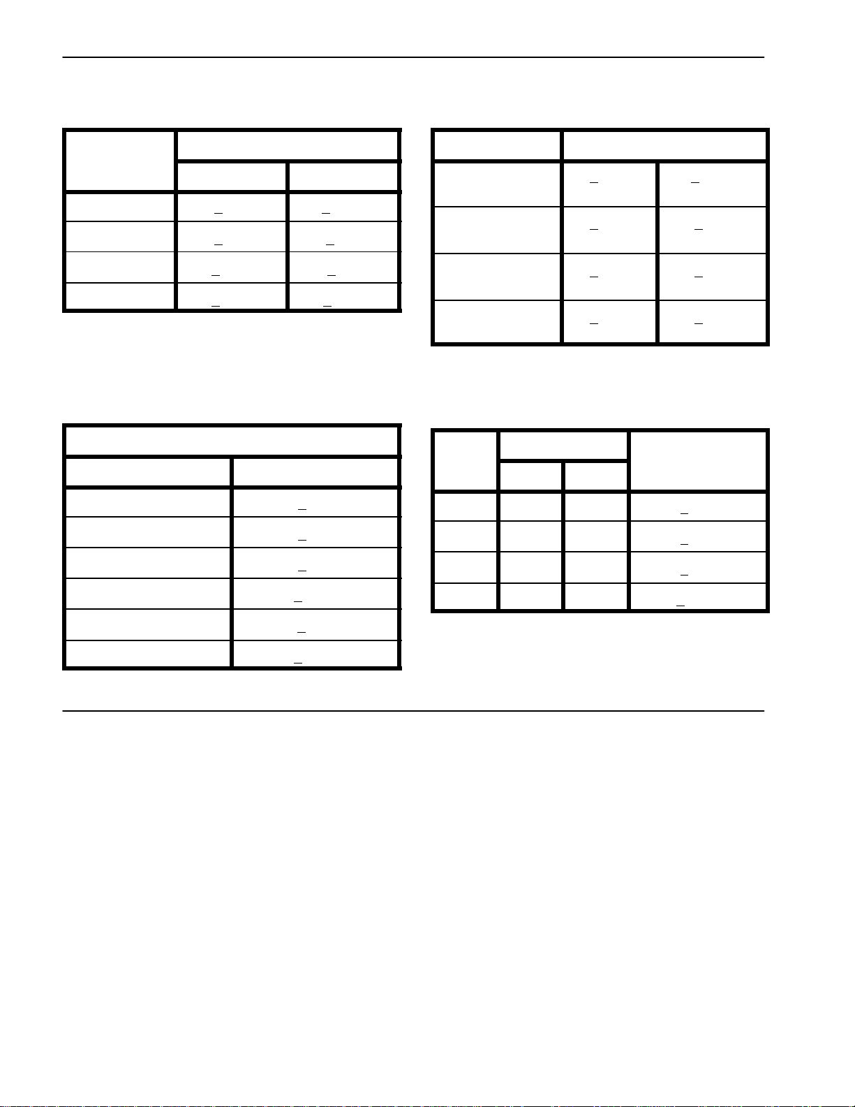
Other Torque Specifications
*
SAE Grade 8 Steel Set Screws
Recommended Torque
Thread Size
Square Head Hex Socket
1/4 -- 20 UNC 140 + 20 in--lb 73 + 12 in--lb
5/16 -- 18 UNC 215 + 35 in--lb 145 + 20 in--lb
3/8 -- 16 UNC 35 + 10 ft--lb 18 + 3ft--lb
1/2 -- 13 UNC 75 + 15 ft--lb 50 + 10 ft--lb
Thread Cutting Screws
(Zinc Plated Steel)
Type 1, Type 23 or Type F
Thread Size Baseline Torque*
No. 6 -- 32 UNC 20 + 5in--lb
Wheel Bolts and Lug Nuts
Thread Size
7/16 -- 20 UNF
Grade 5
1/2 -- 20 UNF
Grade 5
M12 X 1.25
Class 8.8
M12 X 1.5
Class 8.8
** For steel wheels and non--lubricated fasteners.
Thread Cutting Screws
(Zinc Plated Steel)
Thread
Size
No. 6 18 20 20 + 5in--lb
Threads per Inch
Type A Type B
Recommended Torque**
65 + 10 ft--lb 88 + 14 N--m
80 + 10 ft--lb 108 + 14 N--m
80 + 10 ft--lb 108 + 14 N--m
80 + 10 ft--lb 108 + 14 N--m
Baseline Torque
No. 8 -- 32 UNC 30 + 5in--lb
No. 10 -- 24 UNC 38 + 7in--lb
1/4 -- 20 UNC 85 + 15 in--lb
5/16 -- 18 UNC 110 + 20 in--lb
3/8 -- 16 UNC 200 + 100 in--lb
Conversion Factors
in--lb X 11.2985 = N--cm N--cm X 0.08851 = in--lb
ft--lb X 1.3558 = N--m N--m X 0.7376 = ft--lb
No. 8 15 18 30 + 5in--lb
No. 10 12 16 38 + 7in--lb
No. 12 11 14 85 + 15 in--lb
*Holesize,materialstrength,materialthicknessandfinish must be considered when determining specific
torquevalues.All torquevaluesarebasedon non--lubricated fasteners.
Groundsmaster 5900/5910Page 2 -- 6Product Records and Maintenance
Page 19

Table of Contents
GENERAL INFORMATION 2.....................
Operator’s Manual 2..........................
Engine Identification 2.........................
Engine Electronic Control Module (ECM) 2.......
Stopping the Engine 3.........................
Fuel Injection System 3........................
ENGINE SPECIFICATIONS 4....................
ENGINE FASTENER TORQUE SPECIFICATIONS 5
ADJUSTMENTS 7..............................
Valve Clearance 7............................
SERVICE AND REPAIRS 8......................
Air Filter System 8............................
Exhaust System 10...........................
Turbocharger 12..............................
Fuel System 14...............................
Check Fuel Lines and Connections 14..........
Drain and Clean Fuel Tank 14.................
Fuel Tank Removal 15.......................
Fuel Tank Installation 15......................
Chapter 3
Diesel Engine
Radiator 16..................................
Alternator 18.................................
Starter Motor 20..............................
Valve Cover 22...............................
Engine Breather System 24....................
Thermostat 26................................
Water Pump 28...............................
Front Cover 30...............................
Oil Pan 34...................................
Engine 36....................................
Engine Removal 36..........................
Engine Installation 38........................
Flywheel Coupling Assembly 40................
Diesel
Engine
Groundsmaster 5900/5910 Page 3 -- 1 Diesel Engine
Page 20

General Information
This Chapter gives information about specifications of
the Cummins B3.3 diesel engine used in the Groundsmaster 5900 and 5910. Additionally, some engine repairproceduresaredescribedinthismanual.Described
adjustments and repairs require tools which are commonly available in many service shops.
Some service and repair parts for the engine in your
Groundsmaster are supplied through your Authorized
Toro Distributor. Bepreparedto provide your distributor
with the Toro model andserial number ofyourmachine
to obtain parts.
Operator’s Manual
The Operator’s Manualprovides informationregarding
the operation, general maintenance and maintenance
intervals for your Groundsmaster machine.Refertothe
Operator’s Manualfor additional information when servicing the machine.
Engine Identification
Detailedinformationonengine troubleshooting, testing,
disassembly and reassembly is identified in the Cummins Service Manual that is available from Cummins.
The use of some specialized tools and test equipment
is explained in the CumminsServiceManual.However,
the specialized natureof some engine repairs maydictate that the work be done at an engine repair facility.
The engine dataplate located near the startermotor includes the engine serial number and control parts list
number. The fuel injection dataplate is located on the
fuel injection pump. The ECM dataplate is on the electroniccontrolmoduleattachedtotheflywheelend of the
engine. These engine identification tags will assist in
identifying the correct partsand serviceinformation for
the Cummins engine in your Groundsmaster.
Engine Electronic Control Module (ECM)
TheCumminsenginethat isusedintheGroundsmaster
5900 and 5910 uses an electronic control module
(ECM) for engine management and also to communicatewiththeTECcontrollersandtheoperator Info Center on the machine. All engine ECM electrical
connectors should be plugged intothecontrollerbefore
themachineignitionswitch ismovedfromtheOFF position to either the ON or START position. If the engine
ECM is to be disconnected for any reason, make sure
thattheignitionswitch isintheOFFposition with thekey
removed before disconnecting the ECM. Also, to preventpossiblemoduledamagewhenweldingon the machine,disconnectandremovetheengineECM from the
engine before welding.
Groundsmaster 5900/5910Page 3 -- 2Diesel Engine
Page 21

Stopping the Engine
IMPORTANT: Before stopping the engine after
mowing or full load operation, allow the engine to
runatlowidlespeedfor five (5) minutes.Thiswillallow the turbocharger and internal engine components to adequately cool down.Failuretoallow this
cooldown period may lead to premature turbocharger and engine failure.
Fuel Injection System
The engine fuelinjection system operatesat high pressures during engine operation. Do not loosen any fuel
system components, fittings or hoses while the engine
is running.
Keepbodyandhandsawayfromleaksinenginefuel injection lines.Use cardboard or paper to find high pressure fuel leaks if they may exist. Leaking fuel under
pressure can penetrate skin and cause injury.
Diesel
Engine
Groundsmaster 5900/5910 Page 3 -- 3 Diesel Engine
Page 22

Engine Specifications
Item Description
Make / Designation Cummins, 4--Cycle, 4 Cylinder,
Bore 3.74 in (95.0 mm)
Stroke 4.53 in (115 mm)
Total Displacement 201 in3(3300 cc)
Firing Order 1 (Closest to Engine Pulley) -- 2 -- 4 -- 3
Direction of Rotation Clockwise (Viewed from EnginePulley)
Compression Ratio 17:1
ValveClearance
Intake 0.014” (0.35 mm)
Exhaust 0.020” (0.50 mm)
Fuel Diesel or Biodiesel (up to B20) with Low/Ultra Low Sulfur Content
Fuel TankCapacity 35 U.S. gallons (132 liters)
Fuel Injection Pump Zexel Rotary Type VE Pump
Injection Nozzle Closed Nozzle, Hole Type
Liquid Cooled, Turbocharged, Diesel Engine
Governor Electronic
Low Idle (no load) 1350 RPM
High Idle (no load) 2750 RPM
Oil Pump Geroter Type
Engine Oil API CH--4 or CI--4 (see Operator’s Manual for Viscosity)
Crankcase Oil Capacity 8.5 U.S.quarts (8.0 liters) with Filter
Starter 12 VDC, 2.2 kW
Alternator/Regulator 12 VDC, 120 AMP
Coolant Capacity
GM 5900 (without cab) 13.5 U.S. quarts (12.8 liters)
GM 5910 (with cab) 18 U.S. quarts (17 liters)
Engine Dry Weight 606 U.S. pounds (275 kg)
Groundsmaster 5900/5910Page 3 -- 4Diesel Engine
Page 23

Engine Fastener Torque Specifications
Item Description
Alternator Adjusting Cap Screw 23 ft--lb (31 N--m)
Alternator Mounting Bracket Cap Screw (2 used) 23 ft--lb (31 N--m)
Alternator Mounting Cap Screw 49 ft--lb (66N--m)
Crankshaft Pulley Bolt 274 ft--lb (372 N--m)
Exhaust Manifold Flange Head Screw (8 used) 33 ft--lb (45 N--m)
Front Cover Flange Head Screw (16 used) 14 ft--lb (19 N--m)
Oil Drain Plug 38 ft--lb (51 N--m)
Oil Pan Flange Head Screw (24 used) 24 to 38 ft--lb (32 to 51 N--m)
Oil Suction Tube Flange Head Screw (2 used) 14 ft--lb (19 N--m)
Starter Mounting Flange Head Screw (2 used) 32 ft--lb (43 N--m)
Thermostat Housing Flange Head Screw (2 used) 14 ft--lb (19 N--m)
Turbocharger Mounting Nut (4 used) 22 ft--lb (30 N--m)
Turbocharger Oil Drain Line Cap Screw (2 used) 18 ft--lb (24 N--m)
Turbocharger Oil Supply Line Banjo Bolt 18 ft--lb (24 N--m)
ValveAdjustment Nut (rocker arm) 29to36ft--lb(39to49N--m)
ValveCover Nut (3 used) 80 in--lb (9 N--m)
Water Pump Pulley Flange Head Screw (4 used) 23 ft--lb (31 N--m)
Diesel
Engine
Groundsmaster 5900/5910 Page 3 -- 5 Diesel Engine
Page 24

This page is intentionally blank.
Groundsmaster 5900/5910Page 3 -- 6Diesel Engine
Page 25
Adjustments
Valve Clearance
1. Park machine on a level surface, lower cutting
decks, stop engine, engage parkingbrake andremove
key from the ignition switch.
2. Raise and support hood.
3. Remove valve cover from engine (see Valve Cover
RemovalintheServiceandRepairssectionofthischapter).
4. Position engine crankshaft so cylinder #1 is at top
deadcenter(TDC)attheendofthecompression stroke:
A. While watching the movement of the cylinder #4
intakevalve,rotate enginecrankshaftinnormal rotation direction (clockwise). When the cylinder #4 intakevalve starts to open,cylinder#1is approaching
TDC at the end of the compression stroke.
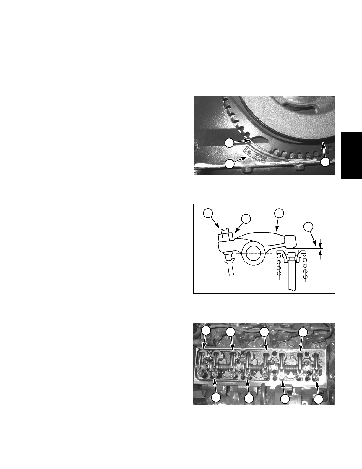
B. Continue rotating the crankshaft in the normal
rotation direction (clockwise) until the cutout in the
tone wheel attached to the back of the crankshaft
pulleyalignswith“1.4TOP”castinenginefrontcover
(Fig. 1).
5. Inthiscrankshaftposition,adjustvalve clearance for
intakevalvesforcylinders#1and#3andexhaustvalves
for cylinders #1 and #2 (Fig. 2 and 3).
8. Installvalvecovertoengine(seeValveCoverInstallationintheServiceandRepairssectionofthis chapter).
9. Lower and secure hood.
2
3
1
Figure 1
1. Crankshaft pulley
2. Tone wheel cutout
2
3. TDC indicator
3
1
4
Diesel
Engine
A. Loosenthelock nutontherocker armadjustment
screw.
B. Insert correct feeler gauge between the valve
stem and the rocker arm. Intake valve clearance
specification is 0.014” (0.35 mm). Exhaust valve
clearance specification is 0.020” (0.50 mm).
C. Adjust screw until aslightdragisfeltonthefeeler
gauge.
D. Hold adjustment screw in position and tighten
lock nut to secure valve clearance adjustment.
Torque lock nut from29 to 36 ft--lb (39 to 49 N--m).
E. After tightening lock nut, re--check valve clearance.
6. Rotate crankshaft in the normal rotation direction
(clockwise) one complete revolution. The tone wheel
cutout should again be aligned with “1.4 TOP”.
7. Inthiscrankshaftposition,adjustvalve clearance for
intakevalvesforcylinders#2and#4andexhaustvalves
for cylinders #3 and #4. Follow procedureunder step5
above.
1. Lock nut
2. Adjustment screw
8
6
7
1. #1 intake
2. #1 exhaust
3. #2 intake
4. #2 exhaust
Figure 2
5
Figure 3
3. Rocker arm
4. Valve clearance
4
3
5. #3 intake
6. #3 exhaust
7. #4 intake
8. #4 exhaust
2
1
Groundsmaster 5900/5910 Page 3 -- 7 Diesel Engine
Page 26
Service and Repairs
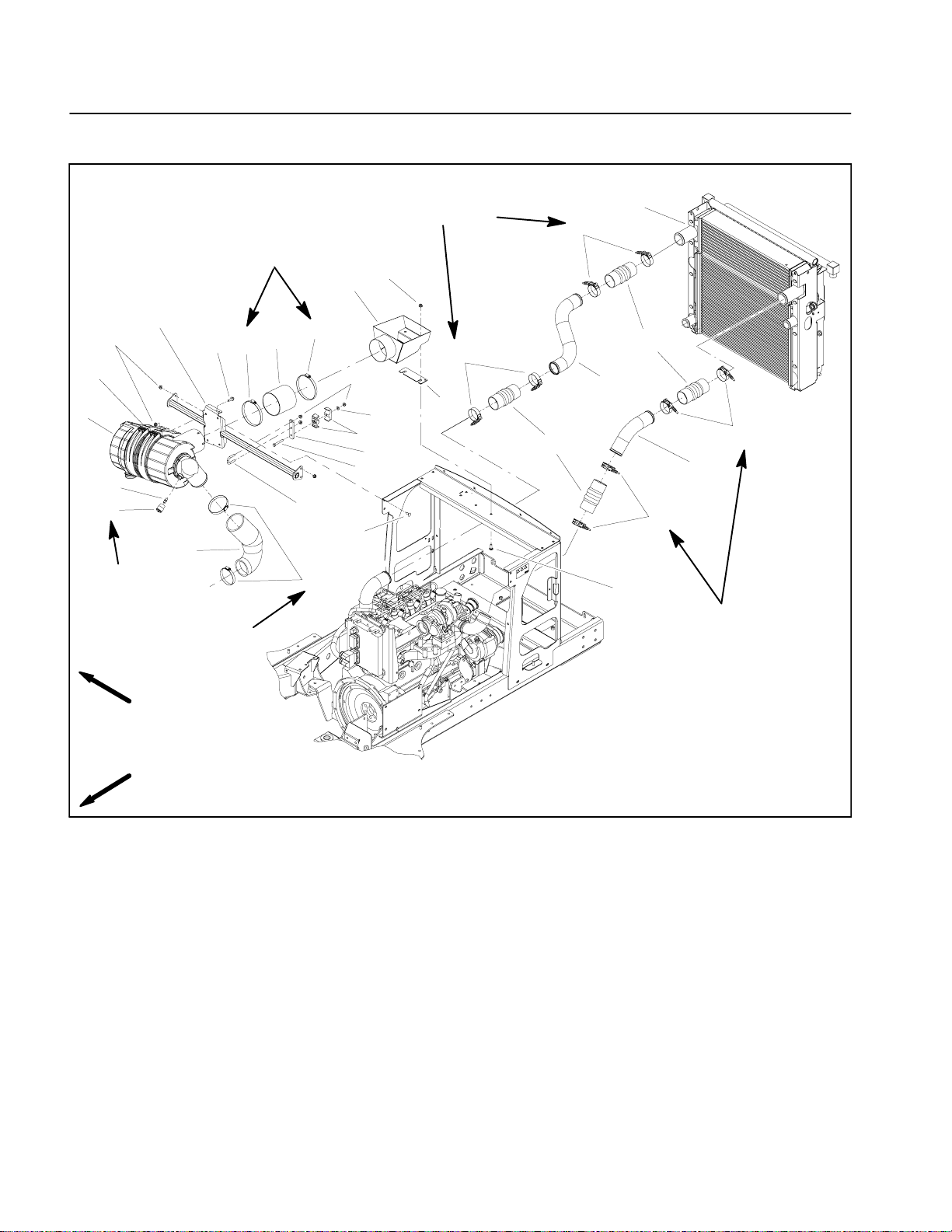
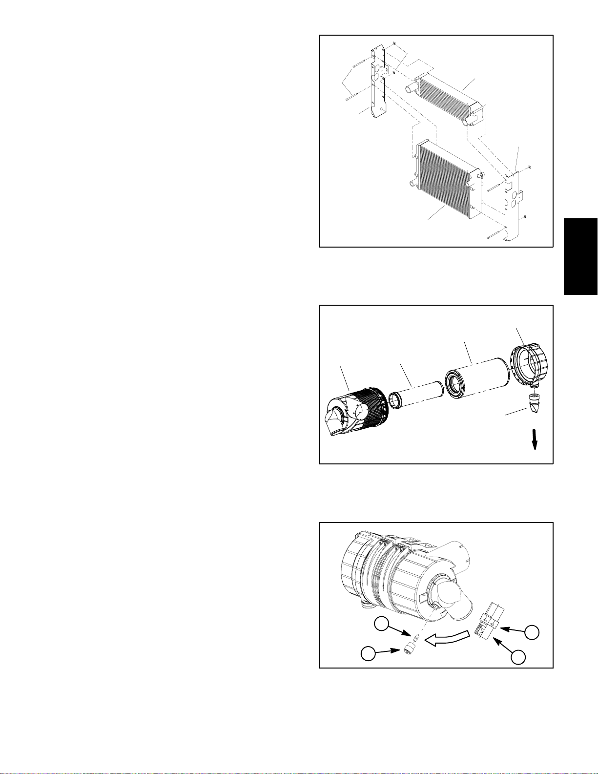
Air Filter System
5
6
7
8
9
12 to 15 in--lb
(1.4 to 1.6 N--m)
4
3
11
45 to 55 in--lb
(5.1 to 6.2 N--m)
45 to 55 in--lb
(5.1 to 6.2 N--m)
2
1
12
10
24
50 to 70 in--lb
(5.7 to 7.9 N--m)
3
19
23
1
21
20
19
22
17
15
13
14
16
19
25
21
19
18
26
50 to 70 in--lb
(5.7 to 7.9 N--m)
RIGHT
FRONT
1. Clamp
2. Air hose
3. Flange head screw (6 used)
4. Air cleaner mount
5. Flange nut (8 used)
6. Air cleaner mounting band (2 used)
7. Air cleaner assembly
8. Adapter
9. Service indicator
Figure 4
10. Worm clamp
11. Intake tube
12. U--bolt
13. Cap screw
14. Mount plate
15. Tube clamp
16. Flat washer
17. Flange nut (3 used)
18. Carriage screw (4 used)
19. Hose clamp (8 used)
20. Tube
21. Air intake tube (4 used)
22. Tube
23. Radiator assembly
24. Airbox
25. Spacer plate (as needed)
26. Carriage screw (2 used)
Groundsmaster 5900/5910Page 3 -- 8Diesel Engine
Page 27
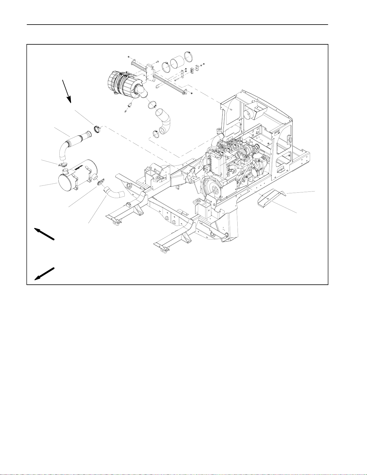
Removal (Fig. 4)
1. Park machine on a level surface, lower cutting
decks, stop engine, engage parkingbrake andremove
key from the ignition switch.
2. Raise and support hood to allow access to engine.
3. Remove air cleaner components as needed using
Figure 4 as a guide.
4. Inspect all tubes andclampsfor evidence of wearor
damage. Replace components as needed.
NOTE: If charge air cooler in radiator assembly needs
to be serviced (Fig. 5), refer to Radiator Removal and
Installation in this section.
Installation (Fig. 4)
IMPORTANT: Any leaks in the air filter system will
causeseriousenginedamage.Makesurethatallair
cleaner components are in good condition and are
properly secured during installation.
5
6
1. Radiator
2. LH cooler bracket
3. Charge air cooler
4
1
Figure 5
3
2
4. Pin clip (8 used)
5. Pin (8 used)
6. RH cooler bracket
Diesel
Engine
1. Assemble air cleaner system using Figure 4 as a
guide.
A. Verify that tabs in air cleaner mounting bands
mesh fully with slots in air cleaner body.
B. Position hose clamps (item 1)so thatthere is no
interference with hood foam when hood is closed.
C. Torque hose clamps (items 1 and 10)from 45 to
55 in--lb (5.1 to 6.2 N--m).
D. Torquehoseclamps(item 19)from50to70 in--lb
(5.7 to 7.9 N--m).
E. Make sure that air cleaner vacuator valve is
pointed down after assembly (Fig. 6).
F. If service indicator (item 8) and adapter (item 9)
wereremovedfromaircleanerhousing,applythread
sealant toadapter threads before installing adapter
and indicator to housing. Install adapter so that
groovesinadapterhexand adapterfilterelementare
installed toward service indicator(Fig.7). Torque indicator from 12 to 15 in--lb (1.4 to 1.6 N--m).
1
1. Air cleaner housing
2. Safety filter
3. Filter element
2
4
3
5
VACUATOR
VALVE
DIRECTION
Figure 6
4. Cover
5. Vacuator valve
2. Apply chalk onairboxlip, lower hoodandcheckthat
hood makes a continuoussealaround airbox (item 24).
If necessary, use shim(s) (item 25) to adjustlocation of
1
4
airbox for proper sealing with hood.
2
3. Lower and secure hood.
3
Figure 7
1. Adapter
2. Service indicator
3. Adapter filter element
4. Adapter grooves
Groundsmaster 5900/5910 Page 3 -- 9 Diesel Engine
Page 28
Exhaust System
50 to 70 in--lb
(5.7 to 7.9 N--m)
1
2
3
4
3
RIGHT
FRONT
1. Exhaust clamp
2. Exhaust tube
3. Muffler clamp (2 used)
7
6
5
Figure 8
4. Muffler
5. Tailpipe
6. Flange head screw (4 used)
7. Heat shield
Groundsmaster 5900/5910Page 3 -- 10Diesel Engine
Page 29
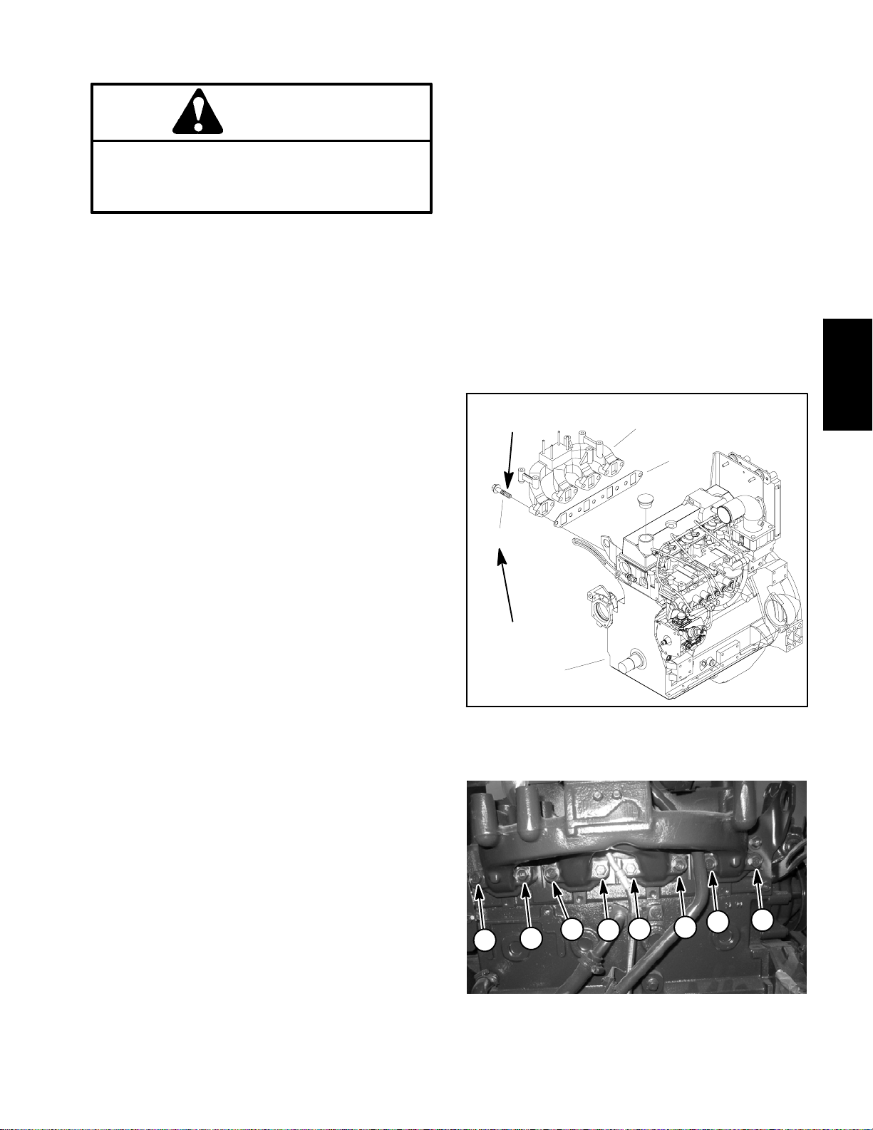
Removal (Fig. 8)
CAUTION
B. Position new manifold gasket and exhaust manifoldtocylinderheadand secure witheight(8)flange
head screws. Tighten the screws in the sequence
shown in Figure 10. Torque screws 33 ft--lb (45
N--m).
The engine and exhaust system may be hot. To
avoid possible burns, allow the engine and exhaust system to cool before working on the exhaust system.
1. Park machine on a level surface, lower cutting
decks, stop engine, engage parkingbrake andremove
key from the ignition switch.
2. Raise and support hood to allow access to exhaust
system.
3. Remove sidepanel from right side offrame to allow
easier access to exhaust system components.
4. Removemufflerand/orexhausttubefromtheengine
as necessary using Figure 8 as a guide.
5. If necessary, remove exhaust manifold from engine
(Fig. 9):
A. Remove turbocharger from exhaust manifold
(see Turbocharger Removal in this section).
B. Support exhaust manifold to prevent it from falling.
C. Secure turbocharger to exhaust manifold (see
Turbocharger Installation in this section).
3. Install muffler and/orexhaust tube to the engineusing Figure 8 as a guide. Torque exhaustclamp (item1)
from 50 to 70 in--lb (5.7 to 7.9 N--m).
4. After exhaust system assembly, check that tailpipe
is approximately parallel to the ground. Loosen clamp
and adjust tailpipe if necessary.
5. Install and secure side panel to right side of frame.
6. Lower and secure hood.
Antiseize
lubricant
4
1
2
Diesel
Engine
C. Removeeight(8)flangehead screwsthatsecure
exhaustmanifoldtocylinderhead.Removemanifold
from engine.
D. Remove and discard manifold gasket. Clean
mating surfaces of cylinder head and manifold.
6. Ifexhaustopeningsaretobeleftopenfor any length
oftime,coveropeningstopreventanymaterialfromfalling into openings.
Installation (Fig. 8)
NOTE: Makesure all exhaust systemsealingsurfaces
are free of debris or damage that may prevent a tight
seal.
1. Removeallcoversandplugsthatwereplacedduring
removal to prevent contamination entry.
2. Installexhaustmanifoldtoengineifremoved(Fig.9):
A. Apply antiseize lubricant to threads of flange
head screws used to secure exhaust manifold.
33 ft--lb
(45 N--m)
3
1. Exhaust manifold
2. Manifold gasket
4
8
6
Figure 9
1
2
Figure 10
3. Engine
4. Flange screw (8 used)
5
3
7
Groundsmaster 5900/5910 Page 3 -- 11 Diesel Engine
Page 30
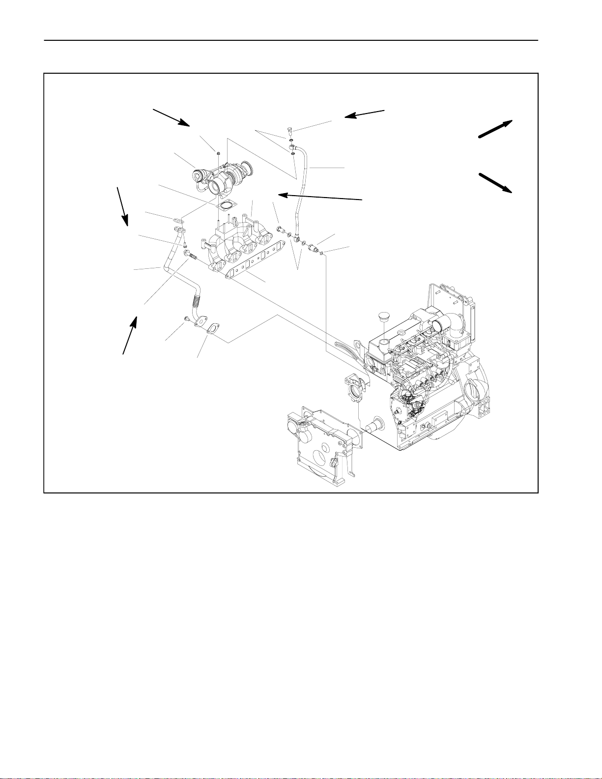
Turbocharger
22 ft--lb
(30 N--m)
18 ft--lb
(24 N--m)
33 ft--lb
(45 N--m)
15
16
17
14
18
13
18 ft--lb
2
4
1
5
6
7
3
(24 N--m)
FRONT
RIGHT
18 ft--lb
(24 N--m)
9
10
8
11
12
1. Turbocharger assembly
2. Flange nut (4 used)
3. Banjo bolt
4. Sealing washer
5. Oil supply tube
6. Exhaust manifold
7. Banjo bolt
Figure 11
8. Sealing washer
9. Coupling
10. O--ring
11. Exhaust manifold gasket
12. Gasket
13. Flange head screw(2 used)
14. Flange head screw(8 used)
15. Oil drain tube
16. Flange head screw(2 used)
17. Gasket
18. Turbocharger gasket
Groundsmaster 5900/5910Page 3 -- 12Diesel Engine
Page 31

Removal (Fig. 11)
CAUTION
9. Carefully lift turbocharger from exhaust manifold.
10.Cover engine, air cleaner and turbocharger openings to prevent any material from falling into openings.
Also, plug openings in oil supply and drain lines.
The engine and exhaust system may be hot. To
avoid possible burns, allow the engine and exhaust system to cool before working on the
turbocharger.
1. Park machine on a level surface, lower cutting
decks, stop engine, engage parkingbrake andremove
key from the ignition switch.
2. Raise and support hood to allow access to engine.
3. Thoroughly clean turbochargerareatoprevent contaminants from entering engine.
4. Loosen clamps that secure exhaust tube to turbocharger outletand muffler inlet. Remove exhaust tube.
5. Loosen clamps that secure air intake tube to turbocharger inlet and air cleaner outlet. Remove air intake
tube.
6. Remove two (2) cap screws that secure oil drainline
to turbocharger. Separateoil drainline fromturbocharger.
7. Remove banjo bolt that secures oil supply line to
turbocharger. Separate oil supply line from turbocharger.
8. Removefour(4)nuts thatsecureturbochargertoexhaust manifold.
Installation (Fig. 11)
NOTE: Makesuremufflerflangeand exhaust manifold
sealing surfaces are free ofdebris or damage that may
prevent a tight seal.
1. Install newgaskets if original gasket wasdamaged.
2. Removeallcoversandplugsthatwereplacedtoprevent contamination entry.
3. Position turbocharger to exhaust manifold and secure with four (4) nuts. Torque nuts 22 ft--lb (30 N--m).
4. Positionoildrainlinetoturbochargerandsecurewith
two (2) cap screws. Torque screws 18 ft--lb (24 N--m).
5. Pour clean engine oil into oil supply line port to ensure turbocharger lubrication on start--up.
6. Position oil supply line to turbocharger and secure
with banjo bolt. Torque banjo bolt 18 ft--lb (24 N--m).
7. Fit air intake tube to turbochargerinletandaircleaner outlet. Secure intake tube with clamps.
8. Fit exhaust tube to turbocharger outlet and muffler
inlet. Secure exhaust tube with clamps.
9. Lower and secure hood.
Diesel
Engine
Groundsmaster 5900/5910 Page 3 -- 13 Diesel Engine
Page 32

Fuel Tank
RIGHT
11
10
12
14
13
19
17
18
16
15
1
2
20
21
3
5
22
21
4
9
21
6
5
7
8
FRONT
1. Fitting cover
2. Screw (3 used)
3. Fuel supply standpipe
4. Fuel return standpipe
5. Bushing (2 used)
6. Elbow fitting
7. Bushing
8. Fuel tank
9. Fuel hose (2 used)
10. Flange nut (2 used)
11. Tank hold down
12. Flange head screw(2 used)
13. Clamp (2 used)
14. Cap
15. Plug (4 used)
DANGER
Becausedieselfuelishighly flammable,usecaution when storing or handling it. Do not smoke
while filling the fuel tank. Do not fill fuel tank
while engine is running, hot or when machine is
in an enclosedarea. Always fill fueltank outside
and wipe up any spilled diesel fuel before starting the engine. Store fuel in a clean, safety--approved container and keep cap in place. Use diesel fuelas an engine fuel only; not for any other
purpose.
Figure 12
16. Gasket
17. Fuel sender
18. Lock washer (5 used)
19. Screw (5 used)
20. Fuel hose
21. Worm clamp (3 used)
22. Fuel hose
Check Fuel Lines and Connections
Checkfuellinesand connections periodically asrecommendedintheOperator’s Manual. Check lines for deterioration,damage, leaks or loose connections.Replace
hoses, clamps and connections as necessary.
Drain and Clean Fuel Tank
Drain and clean the fuel tank periodically as recommendedintheOperator’sManual.Also,drain and clean
the fuel tank if the fuel system becomes contaminated
or if themachineis to bestoredfor an extendedperiod.
To clean fuel tank, flush tank out with clean diesel fuel.
Make sure tank is free of contaminates and debris.
Groundsmaster 5900/5910Page 3 -- 14Diesel Engine
Page 33

Fuel Tank Removal (Fig. 12)
1. Park machine on a level surface, lower cutting
decks, stop engine, engage parkingbrake andremove
key from the ignition switch.
2. Chock rear wheels and jack up front of machine.
Support machine on jack stands. Remove front, left
wheel to allow fuel tank removal.
3. Useafueltransferpumptoremovefuelfromthefuel
tank and into a suitable container.
4. Removethree(3) socketheadscrews thatsecurefitting cover (item 1) to fuel tank. Remove fitting cover.
5. Disconnect power (blue/red) and ground (black)
wires from the fuel sender on the fuel tank (Fig. 13).
5. Using labels placed during tank removal, correctly
connect fuel hoses to thefuel supply standpipe, the return standpipe andthevent elbow fitting.Secure hoses
with hose clamps.
6. Connect electrical wiring to the fuel sender.
A. Connect blue/red wireto the centerterminal and
black wire to any of the screws that secure the fuel
sender to the fuel tank.
B. Apply skin--over grease (ToroPartNo.505--165)
to the wire terminal connections.
7. Position fitting cover to fuel tank and secure with
three (3) socket head screws.
6. Labelfuelhosestoassure properassembly.Disconnect fuel hosesfrom the fuelsupply standpipe (item 3),
the return standpipe (item 4) and the vent elbow fitting
(item 6) in top of tank (Fig. 13).
7. Route fuel lines from under clamps (item 13) that
route fuel lines from standpipes. If necessary, remove
plugs and clamps from top of tank.
8. Remove two (2) flange head screws and lock nuts
that secure tankhold down (item11) to frame.Remove
tank hold down.
9. Slide fuel tank from left side of machine to remove
tank.
10.If necessary, remove standpipes, elbow bushings
and fuel sender from fuel tank.
Fuel Tank Installation (Fig. 12)
1. If removed, install standpipes, elbow bushings and
fuel sender into fuel tank.
2. Install fuel tank from left side of machine.
WARNING
Failure to maintain proper torque couldresultin
failureorlossof wheel andmayresultin personal injury.
8. Install front, left wheel assembly.
9. Lower machine to ground. Torque wheel lug nuts in
a crossing pattern from70 to 90 ft--lb (95 to 122N--m).
10.Fill fuel tank.
4
5
1
6
2
3
Diesel
Engine
3. Position tank hold down (item 11) to fuel tank and
machine frame. Secure hold down with two (2) flange
head screws and lock nuts.
1. Sender power wire
2. Sender ground wire
3. Fuel sender
Figure 13
4. Fuel supply hose
5. Return fuel hose
6. Vent hose
4. Route fuel supplyand return hosesunder clamps in
top of tank.
Groundsmaster 5900/5910 Page 3 -- 15 Diesel Engine
Page 34

Radiator
Thread Sealant
RIGHT
FRONT
29
50 to 70 in--lb
(5.7 to 7.9 N--m)
14
33
15
38
33
25
31
13
21
34
39
37
6
35
25
31
1
24
26
33
32
28
30
2
23
26
2
3
36
4
5
31
25
27
8
6
7
10
22
31
25
18
11
9
10
12
15
14
16
20
17
19
50 to 70 in--lb
(5.7 to 7.9 N--m)
40
1. Radiator assembly
2. Flange nut (4 used)
3. Support plate (2 used)
4. Flange nut (4 used)
5. Rubber pad (4 used)
6. Hose clamp (3 used)
7. Upper radiator hose
8. Overflow hose
9. Hose clamp
10. Worm clamp (5 used)
11. Barb fitting
12. Drain cock fitting
13. Fan shroud
14. Air intake tube (4 used)
15. Hose clamp (8 used)
16. Tube
17. Coolant reservoir
18. Grommet (2 used)
19. Lock nut (2 used)
20. Hose
21. Cap screw (4 used)
22. Hose
23. Radiator cap
24. Support rod
25. Flat washer (10 used)
26. Flange nut (4 used)
27. Hose sleeve
Removal (Fig. 14)
1. Park machine on a level surface, lower cutting
decks, stop engine, engage parkingbrake andremove
key from the ignition switch.
2. Raise andsupport hoodto allow access to radiator.
Figure 14
28. Cap screw (2 used)
29. Tube
30. Washer (4 used)
31. Flange nut (14 used)
32. Clamp (2 used)
33. Carriage screw (14 used)
34. Lower radiator hose
35. Fan motor bracket
36. Fitting
37. Coolant level sensor
38. Cap screw (2 used)
39. Reservoir cap
40. Flat washer (2 used)
3. Rotate clamps that secure oil cooler to radiator
frame. Tilt oil cooler toward rear of machine.
4. Loosenhoseclampsanddisconnect airintaketubes
(item14) from the charge air cooler.
5. Disconnectwireharnessconnectorfromcoolantlevel sensor on right side of radiator.
Groundsmaster 5900/5910Page 3 -- 16Diesel Engine
Page 35

CAUTION
6. Connect air intake tubes (item14) to the charge air
cooler and secure with hose clamps. Torque clamps
from 50 to 70 in--lb (5.7 to 7.9 N--m).
Do not open radiator cap or drain coolant if the
radiator or engine is hot. Pressurized, hot coolant can escape and cause burns.
Ethylene--glycol antifreeze is poisonous. Dispose of coolantproperly, orstore it in aproperly
labeled container away from children and pets.
6. Drain radiatorinto a suitable container using the radiator drain. The radiator drain is located near the hydraulic 4WD manifold (Fig. 15).
7. Loosenhoseclampsand disconnect upper and lower coolant hoses (item 6) from the radiator.
8. Loosen hose clampthat secures coolant drainhose
tofitting(item 36)onbottomofradiator.Removecoolant
drain hose assembly from radiator.
9. Disconnectreservoirhose(item22)fromtheradiator
vent tube.
10.Detach radiator from the fan shroud and support by
removingtwo(2) carriagescrews(item33),flatwashers
and flange nuts.
7. Connect wire harness connector to coolant level
sensor on right side of radiator.
8. Install coolant drain hose assemblytoradiatorfitting
and secure with hose clamp.
9. Connectreservoirhose(item22)totheradiator vent
tube and secure with hose clamp.
10.Make sure radiator drain is closed. Fill radiatorwith
coolant.
11.Secure oil cooler to radiator frame.
12.Run engine and check for any coolant leaks.
13.Lower and secure hood.
3
1
Diesel
Engine
11.Tilt radiator and charge air cooler assembly toward
rearof machine and carefully lift assembly fromthe machine.
12.Plug all radiator and hoseopenings to prevent contamination.
13.Inspect rubber pads (item 5) at bottom of radiator.
Replace pads if worn or damaged.
14.Disassemble radiator and charge air cooler assembly as needed using Figure 16 as a guide.
Installation (Fig. 14)
1. Assemble radiator and charge air cooler assembly
as needed using Figure 14 as a guide. Apply thread
sealant to coolant level sensor if it was removed.
2. Remove plugs from radiator and hoses placed during the removal procedure.
3. Carefully lower radiator and charge air cooler assembly into the machine.
4. Attach radiator to the fan shroud and support with
two (2) carriage screws, flat washers and flange nuts.
1. Radiator hose
2. Radiator drain
5
6
2
Figure 15
3. Air intake tube
4
3
2
1
5. Connect upper and lower coolant hoses (item 6) to
the radiator. Secure hoses with hose clamps.
1. Radiator
2. LH cooler bracket
3. Charge air cooler
Figure 16
4. Pin clip (8 used)
5. Pin (8 used)
6. RH cooler bracket
Groundsmaster 5900/5910 Page 3 -- 17 Diesel Engine
Page 36

Alternator
FRONT
23 ft--lb
(31 N--m)
RIGHT
49 ft--lb
(66 N--m)
3
11
5
1
12
6
7
8
10
13
4
4
9
2
1. Alternator
2. Front cover
3. Belt
4. Bevel washer (2 used)
5. Flange head screw
Figure 17
6. Flat washer
7. Hex nut
8. Flange head screw (2 used)
9. Alternator bracket
10. Cap screw
11. Water pump
12. Adjusting bracket
13. Alternator bracket
Groundsmaster 5900/5910Page 3 -- 18Diesel Engine
Page 37

Removal (Fig. 17)
Installation (Fig. 17)
1. Park machine on a level surface, lower cutting
decks, stop engine, engage parkingbrake andremove
key from the ignition switch.
2. Raise and support hood to allow access to engine.
3. Remove battery accesspanel. Disconnect negative
battery cable first and then positive battery cable (see
Battery Removal in the Service and Repairs section of
Chapter 5 -- Electrical System).
4. Loosen flange head screw (item 5) that secures alternator to adjusting bracket. Rotate alternator toward
enginetoloosendrivebelt.Removebeltfromalternator
pulley.
5. Inspect drive belt for glazing or damage. Replace
belt if necessary.
6. For assemblypurposes, labelall wires that connect
toalternator.Disconnect wiresfromalternatorterminals
and position wires away from alternator.
7. Support alternator to prevent it from shifting or falling.
1. Position alternator to engine brackets.
2. Secure alternator to mounting brackets and adjust-
ingbracketwithremovedfastenersandwashers.Donot
fully tighten fasteners.
3. Place drivebelt on alternator pulley. Rotate alterna-
tor away from engine to properly tension drive belt.
4. Tighten screws to secure alternator. Torque cap
screw at mounting bracket (item 10) to 49 ft--lb (66
N--m). Torque flange head screw at adjusting bracket
(item 5) to 23 ft--lb (31 N--m).
5. Using labels placed during alternator removal, cor-
rectly connect all wires to alternator terminals.
6. Connectpositivebatterycable topositivebatteryter-
minal.Then,connectnegativebatterycable tonegative
battery terminal (see Battery Installation in the Service
and Repairs section of Chapter 5 -- Electrical System).
Install battery access panel.
7. Lower and secure hood.
Diesel
Engine
8. Remove flange head screw andflat washer thatsecure alternator to adjusting bracket (item 12). Remove
cap screw, two (2) bevel washers and hex nut that secure alternator to mounting brackets (items 9 and 13).
9. Carefully remove alternator from engine and machine.
Groundsmaster 5900/5910 Page 3 -- 19 Diesel Engine
Page 38

Starter Motor
32 ft--lb
(43 N--m)
FRONT
RIGHT
1
2
3
Figure 18
1. Engine 2. Starter motor 3. Flange head screw (2 used)
Groundsmaster 5900/5910Page 3 -- 20Diesel Engine
Page 39

Removal (Fig. 18)
Installation (Fig. 18)
1. Park machine on a level surface, lower cutting
decks, stop engine, engage parkingbrake andremove
key from the ignition switch.
2. Raise and support hood to allow access to engine.
3. Remove battery accesspanel. Disconnect negative
battery cable first and then positive battery cable (see
Battery Removal in the Service and Repairs section of
Chapter 5 -- Electrical System).
4. Label all wires that connect to starter for assembly
purposes. Disconnect wiresfrom starter terminals.and
position away from starter (Fig. 19).
A. Removenutand lockwasherthatsecurecableto
starter stud. Remove cable from starter stud.
B. Loosen screw used to secure harness blue wire
to starter solenoid. Unplug wire from starter.
5. Support starter to prevent it from shifting or falling.
6. Remove two (2) flange head screws that secure
starter to engine.
1. Position starter to engine housing.
2. Secure starter to engine with two (2) flange head
screws. Torque screws 32 ft--lb (43 N--m).
3. Using labels placed during removal, correctly con-
nect and secure removed wires to starter terminals.
4. Connectpositivebatterycable topositivebatteryter-
minal.Then,connectnegativebatterycable tonegative
battery terminal (see Battery Installation in the Service
and Repairs section of Chapter 5 -- Electrical System).
Install battery access panel.
5. Lower and secure hood.
2
1
3
Diesel
Engine
7. Carefully remove starter from engine and machine.
1. Starter stud
2. Starter solenoid
Figure 19
3. Screw
Groundsmaster 5900/5910 Page 3 -- 21 Diesel Engine
Page 40

V alve Cover
80 in--lb
(9 N--m)
3
4
2
5
FRONT
RIGHT
6
7
1
1. Engine
2. Valve cover
3. Lock nut (3 used)
Figure 20
4. Flat washer (3 used)
5. Isolation washer (3 used)
6. Oil fill cap
7. Valve cover gasket
Groundsmaster 5900/5910Page 3 -- 22Diesel Engine
Page 41

Removal (Fig. 20)
Installation (Fig. 20)
1. Park machine on a level surface, lower cutting
decks, stop engine, engage parkingbrake andremove
key from the ignition switch.
2. Raise and support hood to allow access to engine.
3. Thoroughly clean valve cover and cylinder head to
prevent contaminant entry into engine.
4. Remove crankcase breather tube from valve cover
(see Engine Breather Removal in this section).
5. Removethree(3)locknuts, flatwashersandisolator
washers.
6. Remove valve cover from cylinder head. Remove
and discard valve cover gasket.
1. Position new gasket and valve cover to cylinder
head.
2. Secure valve cover to cylinder head with three (3)
isolatorwashers,flatwashersandlocknuts.Torquelock
nuts 80 in--lb (9 N--m).
3. Connectcrankcasebreathertubetovalve cover and
secure with hose clamp (see Engine Breather Installation in this section).
4. Check engine oil level and add oil if necessary.
5. Lower and secure hood.
Diesel
Engine
Groundsmaster 5900/5910 Page 3 -- 23 Diesel Engine
Page 42

Engine Breather System
FRONT
RIGHT
15
16
15
14
12
11
13
10
17
12
8
7
9
6
5
4
2
3
1
1. Hose
2. Hose clamp
3. Spacer
4. Breather mount plate
5. Cap screw (2 used)
6. Breather
Figure 21
7. Breather outlet hose
8. Latch plate
9. Hose clamp
10. Breather inlet hose
11. Hose clamp
12. Hose clamp
13. Breather hose
14. Hose barb
15. Hose
16. Check valve
17. Worm clamp
Groundsmaster 5900/5910Page 3 -- 24Diesel Engine
Page 43

Removal (Fig. 21)
1. Park machine on a level surface, lower cutting
decks, stop engine, engage parkingbrake andremove
key from the ignition switch.
2. Raise and support hood to allow access to engine.
3. Clean breather components before removal to prevent contaminant entry into breather system.
4. Remove breather components as necessary using
Figure 21 as a guide.
Installation (Fig. 21)
1. Install removed breather components using Figure
21 as a guide. If removed, make sure that check valve
(item 16) is installed with black side toward the engine
oil pan (Fig. 22).
2. Lower and secure hood.
FROM BREATHER
1
2
TOWARD ENGINE
Figure 22
1. Base (gray) 2. Cover (black)
Diesel
Engine
Groundsmaster 5900/5910 Page 3 -- 25 Diesel Engine
Page 44

Thermostat
1. Water pump
2. Seal
6
5
4
3
2
14 ft--lb
(19 N--m)
1
Figure 23
3. Thermostat
4. Gasket
5. Thermostat housing
6. Flange head screw (2 used)
Removal (Fig. 23)
1. Park machine on a level surface, lower cutting
decks, stop engine, engage parkingbrake andremove
key from the ignition switch.
2. Raise and support hood to allow access to engine.
CAUTION
Do not open radiator cap or drain coolant if the
radiator or engine is hot. Pressurized, hot coolant can escape and cause burns.
Ethylene--glycol antifreeze is poisonous. Dispose of coolantproperly, orstore it in aproperly
labeled container away from children and pets.
3. Draincoolantfrom radiatorandengine (seeRadiator
Removal in this section).
4. Remove upper coolant hose from thermostat housing.
5. Removetwo(2)flangeheadscrewsthatsecurethermostat housing to water pump. Remove thermostat
housing.
6. Removethermostatand sealfromwater pumphousing.
7. Clean gasket surfaces of pump and thermostat
housing.
8. Inspect thermostat sealing areas in pump housing.
Thoroughly clean sealing surfaces if any corrosion or
debris buildup is evident.
Thermostat Testing
1. Remove the thermostat (see Water Pump, Hose,
Pipe and Thermostat Removal and Installation).
2. Suspendthethermostat andathermometerinacontainerofwater(Fig. 24). Foraccuratetestresults,donot
allowthethermostator thermometer to contact the container.
Groundsmaster 5900/5910Page 3 -- 26Diesel Engine
Page 45

3. Slowly heat the waterandstir water to allowuniform
watertemperature.Noteandrecord the temperaturefor
the following:
A. The thermostat should start to open at 180
o
C).
(82
o
F
B. The thermostat should be fully open (0.315” (8
o
mm) lift) at 203
F(95oC).
4. If the thermostat fails to open,only partiallyopensor
sticks, it should be replaced.
Installation (Fig. 23)
1. Installseal andthermostatintowaterpumphousing.
2. Position thermostat gasket and housing to water
pump housing. Secure thermostat housingwith two (2)
flange head screws. Torque screws 14 ft--lb (19 N--m).
3. Installuppercoolanthoseto thermostathousingand
secure with hose clamp.
4. Fill cooling system with coolant.
5. Run engine and check for any coolant leaks.
6. Lower and secure hood.
Figure 24
Diesel
Engine
Groundsmaster 5900/5910 Page 3 -- 27 Diesel Engine
Page 46

Water Pump
FRONT
RIGHT
23 ft--lb
(31 N--m)
3
14 ft--lb
(19 N--m)
8
14
5
11
6
13
10
4
1
7
9
12
2
1. Flange head screw (4 used)
2. Water pump pulley
3. Belt
4. Flange head screw
5. Flange head screw (2 used)
Figure 25
6. O--ring
7. Gasket
8. Thermostat housing
9. Flange head screw (3 used)
10. Water pump
11. Thermostat
12. Front cover
13. Seal
14. Gasket
Groundsmaster 5900/5910Page 3 -- 28Diesel Engine
Page 47

Removal (Fig. 25)
Installation (Fig. 25)
1. Park machine on a level surface, lower cutting
decks, stop engine, engage parkingbrake andremove
key from the ignition switch.
2. Raise and support hood to allow access to engine.
CAUTION
Do not open radiator cap or drain coolant if the
radiator or engine is hot. Pressurized, hot coolant can escape and cause burns.
Ethylene--glycol antifreeze is poisonous. Dispose of coolantproperly, orstore it in aproperly
labeled container away from children and pets.
3. Draincoolantfrom radiatorandengine (seeRadiator
Removal in this section).
4. Disconnect wire harness connector from temperature sensor on water pump housing (Fig. 26).
5. Remove upper andlower radiator hoses from water
pump.
1. Make sure that gasket surfaces on engine, water
pump and thermostat housing are thoroughly cleaned.
2. PositionnewO--ringandgaskettowaterpumphous-
ing.
3. Secure water pump to engine with four (4) cap
screws.
4. Ifpulleywas removedfromwaterpumpshaft,secure
pulley with four (4) cap screws. Torque cap screws 23
ft--lb (31 N--m).
5. If thermostatwas removedfrom waterpump, install
thermostat to water pump (see Thermostat Installation
in this section).
6. Install upper and lower radiator hoses to water
pump. Secure hoses with hose clamps.
7. On Groundsmaster 5910 machines:
A. Install and secure cab heater hoses to water
pump.
B. Install and adjust A/C compressor drive belt.
Diesel
Engine
6. On Groundsmaster 5910 machines:
A. Remove cab heater hoses from water pump.
B. Remove A/C compressor drive belt.
7. Remove alternator and drive belt from engine (see
Alternator Removal in this section).
8. Removefour(4)capscrewsthatsecurewaterpump
to engine.
9. Carefully remove water pump from engine.
10.Remove and discard O--ring and gasket from be-
tween water pump and engine.
11.If necessary, remove thermostat from water pump
(see Thermostat Removal in this section). Make sure
that gasket surfaces on water pump and thermostat
housing are thoroughly cleaned.
12.If necessary, remove pulley from water pump.
A. Removefour(4)capscrewsthatsecurepulleyto
pump shaft.
8. Connect wire harness connector to temperature
sensor on water pump (Fig. 26).
9. Install alternator and drive belt toengine (seeAlternator Installation in this section). Adjust drive belt.
10.Fill cooling system with coolant.
11.Run engine and check for any coolant leaks.
12.Lower and secure hood.
1
2
Figure 26
1. Water pump 2. Temperature sensor
B. Pull pulley from pump shaft.
Groundsmaster 5900/5910 Page 3 -- 29 Diesel Engine
Page 48

Front Cover
FRONT
RIGHT
49 ft--lb
(66 N--m)
10
15
14
23 ft--lb
(31 N--m)
5
6
12
7
8
13
4
4
9
3
1
1. Belt
2. Front cover
3. Water pump pulley
4. Bevel washer (2 used)
5. Flange head screw
6. Flat washer
7. Hex nut
11
18
274 ft--lb
(372 N--m)
19
Figure 27
8. Flange head screw (2 used)
9. Alternator bracket
10. Water pump assembly
11. Crankshaft pulley with tone wheel
12. Adjusting bracket
13. Alternator bracket
17
16
2
24 ft--lb
(32 N--m)
14. Cap screw
15. Alternator
16. Flange head screw
17. Oil pan
18. Mounting plate
19. Cap screw
Groundsmaster 5900/5910Page 3 -- 30Diesel Engine
Page 49

Removal (Fig. 27)
1. Park machine on a level surface, lower cutting
decks, stop engine, engage parkingbrake andremove
key from the ignition switch.
2
4
2. Raise and support hood to allow access to engine.
3. Loosen screws that secure alternator to mounting
brackets and rotate alternator toward engine to loosen
drive belt. Remove belt frommachine.
4. On Groundsmaster 5910 machines, remove A/C
compressor drive belt.
5. Removeelectricalcomponents fromfrontcover(Fig.
28):
A. Remove screws that secure electrical harness
clamps to front cover.
B. Removescrewsthat securecrankshaftandcam-
shaft position sensors to front cover.
C. Carefullypulltwo(2)sensorsfromfront cover.In-
spect O--rings onsensors andreplace if necessary.
D. Position wire harness and sensors away from
front cover.
6. Remove five (5) flange head screws that secure oil
pantofrontcover (see Oil Pan Removal in this section).
4
3
1. Crankshaft sensor
2. Camshaft sensor
3. Tone wheel
6
Figure 28
5
5
4. Harness clamp
5. Crankshaft pulley
1
4
1
Diesel
Engine
7. Remove lock nutandthrustwasher that securerear
axlepivotshaft to frame. Slide pivot shaft towardrearof
machine toallow clearance for engine pulley bolt to be
removed (see Rear Axle Removal in the Service and
Repairs section of Chapter 6-- Axles, Planetaries and
Brakes).
8. Remove crankshaft pulley (Fig. 28):
IMPORTANT: When removing crankshaft pulley,
take care to not damage tone wheelthat is secured
to back of pulley.
A. Useappropriateholding tool topreventthepulley
and engine crankshaft from rotating.
B. Loosen and remove cap screw and mounting
plate that secure pulley to crankshaft.
C. Slide pulley fromcrankshaft.Locate and retrieve
woodruff key from crankshaft.
IMPORTANT: Three (3) different lengths of flange
head screws are used to secure the front cover. To
assist with assembly, note location of screws as
they are removed.
4
14 ft--lb
(19 N--m)
3
2
Figure 29
1. Front cover
2. Flange head screw
3. Flange head screw
4. Oil seal
5. Alternator bracket
6. Flange head screw
9. Removesixteen(16) flangeheadscrewsthatsecure
frontcovertoengine(Fig.29).R otate alternator bracket
away from front cover.
10.Carefully remove front cover from engine.
11.Removesealfromfrontcovertakingcaretonotdamage seal bore in cover.
12.Thoroughly clean all removed components. Make
surethat all sealant is removedfromfrontcoversealing
surfaces.
13.Inspectcrankshaftsurfaceinoilsealareaforanyevidenceof wear or damage.Repairorreplacecrankshaft
if necessary.
Groundsmaster 5900/5910 Page 3 -- 31 Diesel Engine
Page 50

Installation (Fig. 27)
1. Make sure that mounting surfaces on engine, front
cover and oil pan are thoroughly cleaned.
9. Secure electrical components to front cover (Fig.
28):
A. Positionwireharness and sensors to front cover.
2. Fill 50% of theseallip space with grease.UseCummins seal installer tool #3164900 (or equivalent) to
install new oil seal into front cover.
3. ApplyCumminssealant#3164067(or equivalent),to
the front cover mounting surfaces. Make sure to apply
sealant to all engine and oil pan mating surfaces.
4. Carefully install front cover to engine taking care to
not damage the oil seal during assembly.
5. Rotate alternator bracket to front cover.
6. Usingnotestakenduringfrontcoverremovaltoidentify correct screw location, securefront cover to engine
withsixteen(16)flange head screws. Torquescrews14
ft--lb (19 N--m).
7. Secureoilpantofrontcoverwithfive(5)flangehead
screws. Torque screws 14 ft--lb (19 N--m).
8. Install crankshaft pulley:
IMPORTANT: When installing crankshaft pulley,
take care to not damage tone wheelthat is secured
to back of pulley.
A. Place woodruff key into crankshaft slot.
B. Carefully slide pulley onto crankshaft making
suretonotdamageoil sealinfrontcover.Also,make
sure to align keyslot in pulley with woodruff key in
crankshaft.
B. Apply a light film of clean oil to crankshaft and
camshaft position sensorsO-- rings. Carefully install
sensors into front cover and secure with screws.
C. Secure electrical harness clamps to front cover.
10.Secure rearaxlepivot shaft to frame(seeRear Axle
Removal in theServiceand Repairs section ofChapter
6-- Axles, Planetaries and Brakes).
A. Slide axle pivot shaft toward front of machine.
Make sure that that roll pin on pivot shaft is positioned in frame reliefs.
B. Installthrustwasher and locknutontopivotshaft.
C. Tightenlocknut to eliminate any axialmovement
of rear axle.Makesure that axlecanstill pivot freely
after lock nut is tightened.
11.Position drivebelttocrankshaft, water pump andal-
ternator pulleys. Tension belt and tighten alternator
mountingscrews (see Alternator Installation in thissection).
12.On Groundsmaster 5910 machines, install and ad-
just A/C compressor drive belt.
13.Check engine oil level and adjust if necessary.
14.Start engine and check for any oil leakage.
15.Lower and secure hood.
C. Install mounting plate (item 18) and cap screw
(item 19) to pulley and crankshaft.
D. Using an appropriate holding tool to prevent the
pulley and engine crankshaft from rotating, torque
cap screw 274 ft--lb (372 N--m).
Groundsmaster 5900/5910Page 3 -- 32Diesel Engine
Page 51

This page is intentionally blank.
Diesel
Engine
Groundsmaster 5900/5910 Page 3 -- 33 Diesel Engine
Page 52

Oil Pan
14 ft--lb
(19 N--m)
FRONT
RIGHT
1
3
8
7
2
14 ft--lb
(19 N--m)
3
38 ft--lb
(51 N--m)
1. O--ring
2. Flat washer
3. Flange head screw (2 used)
5
6
Figure 30
4. Flange head screw (24 used)
5. Sealing washer
6. Drain plug
4
7. Oil pan
8. Oil suction tube
24 ft--lb
(32 N--m)
Groundsmaster 5900/5910Page 3 -- 34Diesel Engine
Page 53

Removal (Fig. 30)
Installation (Fig. 30)
1. Park machine on a level surface, lower cutting
decks, stop engine, engage parkingbrake andremove
key from the ignition switch.
2. Raise and support hood to allow access to engine.
3. Drain oil from engine.
4. Removetwentyfour (24)flangehead screwsthatsecure oil pan to engine.
5. Carefully,remove oil panfrom engine takingcare to
not damage theoil pan or the sealingsurface. Remove
oil pan from engine.
6. Ifnecessary,removetwo(2)flangeheadscrewsthat
secure oil suction tube to engine. Remove oil s uction
tube.
7. Thoroughly clean sealing surfaces of removed components. Inspect parts for cracks or other damage.
1. Ifoilsuctiontubewasremoved,placeO--ringontube
and position tube to engine. Secure with two(2) flange
head screws. Torque screws 14 ft--lb (19 N--m).
2. Using Cummins sealant #3164067 (or equivalent),
apply a 0.039” (1 mm) sealant bead around all oil pan
mounting screw holes. Then, apply a 0.118” (3 mm)
sealant bead to the oil pan mounting surface.
3. Carefully raise oil pan to cleaned engine mounting
surface and secure oil pan to engine with twenty four
(24) flange head screws. Torque screws 24 ft--lb (32
N--m).
4. Make sure thatdrainplug (item 6)isinstalled into oil
pan. Torque drain plug 38 ft--lb (51 N--m).
5. Add oil to engine to the proper level.
6. Start engine and check for any oil leakage.
7. Lower and secure hood.
Diesel
Engine
Groundsmaster 5900/5910 Page 3 -- 35 Diesel Engine
Page 54

Engine
16
14
1
4
4
5
6
7
3
8
9
10
13
12
11
8
RIGHT
FRONT
1. Engine assembly
2. Traction flush manifold
3. Cap screw (8 used)
4. Cap screw (4 used)
5. Rear engine mount (2 used)
6. Lock washer (4 used per mount)
7. Cap screw (4 used per mount)
8. Engine isolator mount (4 used)
9. Snubbing washer (4 used)
10. Lock nut (4 used)
11. Cap screw (4 used per mount)
Engine Removal (Fig. 31)
1. Park machine on a level surface, lower cutting
decks, stop engine, engage parkingbrake andremove
key from the ignition switch.
2. Ifengineis tobedisassembled,drainoilfromengine.
3. Remove hood (see Hood Removal in the Service
and Repairs section of Chapter 7 -- Chassis).
4. Remove battery accesspanel. Disconnect negative
battery cable first and then positive battery cable (see
Battery Removal in the Service and Repairs section of
Chapter 5 -- Electrical System).
15
2
Figure 31
12. Lock washer (4 used per mount)
13. Front LH engine mount
14. Front RH engine mount
15. Flange nut (8 used)
16. 4WD control manifold
CAUTION
Do not open radiator cap or drain coolant if the
radiator or engine is hot. Pressurized, hot coolant can escape and cause burns.
Ethylene--glycol antifreeze is poisonous. Dispose of coolantproperly, orstore it in aproperly
labeled container away from children and pets.
5. Drain coolant from the radiator into a suitable con-
tainer (see Radiator Removal in this section). Disconnect coolant hoses from the radiator.
Groundsmaster 5900/5910Page 3 -- 36Diesel Engine
Page 55

CAUTION
The muffler and exhaust pipe may be hot. To
avoid possible burns, allow the exhaust system
to cool before working on or near the muffler.
6. Remove exhaustsystem fromengine (seeExhaust
System Removal in this section).
2
3
7. Remove air cleaner system from engine (see Air
Cleaner Removal in this section). Also, remove intake
hoses from charge air cooler.
8. Note location of cable ties used to secure electrical
wires. Disconnect wires and/or electrical connections
from the following electrical components:
A. The alternator (Fig 32).
B. The temperature sensor onwater pump housing
(Fig. 33).
C. Battery,frameandwireharness groundattheen-
gine block (Fig. 34).
D. The engine electronic control module.
E. The electric starter motor.
F. The air intake heater.
G. The air conditioning compressor (Groundsmas-
ter 5910 machines) (Fig. 35).
9. Disconnect fuel hose from water separator outlet
(Fig. 36). Cap fuel hose and water separator outlet to
prevent contamination.
Figure 32
1. Alternator
2. Cable
3. Harness connector
1
2
Figure 33
1. Water pump 2. Temperature sensor
1
1
Diesel
Engine
IMPORTANT: Support hydraulic pump assembly to
prevent it from falling and being damaged.
10.Remove hydraulic pumpassemblyfromengine(see
Pump Assembly Removal in the Service and Repairs
section of Chapter 4 -- Hydraulic System).
11.On Groundsmaster 5910 machines,removeairconditioning compressor from brackets (seeAir Conditioning Compressor Removal in the Service and Repairs
3
5
4
8
9
6
7
2
section of Chapter 10 -- Operator Cab). Position compressor away from engine taking care to not damage
compressor or hoses. Support c ompressor to make
sure it will not fall during engine removal.
12.Make surethatallcable ties securing the wiringhar-
1. Positive battery cable
2. Negative battery cable
3. Cap screw
4. Cap screw
5. Internal lock washer
Figure 34
6. Internal lock washer
7. Flange nut
8. Negative battery cable
9. Positive battery cable
ness,fuellinesandhydraulichosesto theengineareremoved.
Groundsmaster 5900/5910 Page 3 -- 37 Diesel Engine
Page 56

CAUTION
Makesurethat hoist orliftusedto remove engine
can properly support engine. Engine weighs
approximately 606 pounds (275 kg).
13.Connect suitable hoistor lift to the front and rearlift
tabs on engine.
14.Remove lock nuts, snubbing washers and cap
screwssecuringtheenginebracketstotheengineisolator mounts.
CAUTION
One person should operatelift or hoist whilethe
other person guides the engine out of the machine.
IMPORTANT: Make sure to not damage the engine,
fuel lines, hydraulic lines,electrical harness or othermachinecomponents while removing theengine.
15.Carefully raise engine from the machine.
1
2
Figure 35
1. AC compressor 2. Connector
2
1
3
16.If necessary, remove engine mount brackets from
the engine.
17.If necessary,remove engineisolatormounts(item8)
from frame. Note that one of the fasteners for the RH
frontmotormountalsosecurestheframegroundcable.
18.Coverorplugallengineopenings topreventcontaminants from entering engine.
Engine Installation (Fig. 31)
1. If removed, install engine mount brackets to engine
and isolator mounts to frame.
2. Make sure that all parts removed from the engine
during maintenance or rebuildingarecorrectly installed
to the engine.
3. Remove all covers and plugsfrom engineopenings
that were placed during engine removal.
CAUTION
Figure 36
1. Water separator
2. Outlet
4. Connect suitable hoist or lift to the front and rear lift
tabs on engine.
3. Fuel hose
CAUTION
One person should operatelift or hoist whilethe
otherpersonguides theengineinto themachine.
IMPORTANT: Make sure not to damage the engine,
fuel and hydraulic lines, electrical harness orother
parts while installing the engine.
5. Slowly lower engine into the machine.
6. Align engine mount brackets to the engine isolator
mountsandsecurewith cap screws, snubbing washers
and lock nuts.
Make sure that hoist orlift used to install engine
can properly support engine. Engine weighs
approximately 606 pounds (275 kg).
7. Connectfuelhosetowaterseparatoroutlet(Fig. 36).
8. Install hydraulic pump assembly to engine (see
Pump Assembly Installationinthe Service andRepairs
section of Chapter 4 -- Hydraulic Systems).
Groundsmaster 5900/5910Page 3 -- 38Diesel Engine
Page 57

9. OnGroundsmaster5910machines,installairconditioning compressor to brackets (see Air Conditioning
CompressorInstallationin theServiceandRepairssectionofChapter 10 -- OperatorCab).Makesure thatdrive
belt is properly tensioned.
10.Using notes taken during engine removal, connect
wiresand/orelectricalconnections tothefollowingelectrical components:
A. The alternator (Fig 32).
B. The temperature sensor onwater pump housing
(Fig. 33).
C. Battery,frameandwireharness groundattheen-
gine block (Fig. 34).
IMPORTANT: When connecting wire harness to
engine electronic control module, make sure
thatharnessconnectortabisalignedwithcorresponding slot in control module.
12.Installexhaustsystem tomachine(seeExhaustSystem Installation in this section).
13.Connect coolanthosestotheradiator.Makesureradiator drain isshut. Fill radiator and reservoir with coolant.
14.Check positionofelectricalharnesses,fuel linesand
hydraulic hoses forproperclearance with rotating,high
temperature and moving components.
15.Connect positive battery cable first and then negativebatterycable(seeBatteryInstallationin the Service
and Repairs section of Chapter 5 -- Electrical System).
Secure batteries to machinewith straps.Install access
panel.
16.Check and adjust engine oil as needed.
17.Check and adjust hydraulic oil as needed.
18.Bleed fuel system.
Diesel
Engine
D. The engine electronic control module.
E. The electric starter motor.
F. The air intake heater.
G. The air conditioning compressor (Groundsmas-
ter 5910 machines) (Fig. 35).
11.Install aircleanerassembly to the engineandintake
hoses tocharge aircooler (see Air Cleaner Installation
in this section). Make sure to torque hose clamps that
secure intake system hosesfrom 45 to 55in--lb (5.1to
6.2 N--m).
19.Run engine and check for any leaks.
20.Operate hydraulic controls to properly fill hydraulic
system (see Charge Hydraulic System in the Service
and Repairs section of Chapter 4 -- Hydraulic System).
21.Install hoodtomachine (see HoodInstallation in the
Service and Repairs section of Chapter 7 -- Chassis).
Groundsmaster 5900/5910 Page 3 -- 39 Diesel Engine
Page 58

Flywheel Coupling Assembly
Permatex
Threadlocker
29 to 33 ft--lb
(40to44N--m)
4
3
2
7
6
5
RIGHT
FRONT
1. Cap screw (12 used)
2. Washer (12 used)
3. Coupling housing
1
Figure 37
4. Cap screw (8 used)
5. Washer (8 used)
6. Flywheel coupling
7. Engine assembly
Groundsmaster 5900/5910Page 3 -- 40Diesel Engine
Page 59

Disassembly (Fig. 37)
1. If engine is in machine, hydraulic pump assembly
needs to be removed from engine before coupling can
be serviced (see Pump Assembly in Chapter 4 -- Hydraulic Systems).
2. Remove coupling housing and flywheel coupling
from engine using Figure 37 as a guide.
Assembly (Fig. 37)
1. Position flywheelcoupling to engineflywheel. Make
sure that coupling hub is away from engine flywheel
(Fig. 38).
2. Apply Permatex Blue Gel medium strength threadlocker (or equivalent)tothreads of cap screws(item 4).
Secure coupling to engine flywheel with eight (8) cap
screws and washers.Torque cap screws from29 to 33
ft--lb (40 to 44 N--m).
3. Positioncouplinghousing toengine.Securehousing
withtwelve(12)capscrewsandwashersusingacrossingpatterntighteningprocedure.Torquescrewsfrom29
to 33 ft--lb (40 to 44 N--m).
4. If engine is in machine, install hydraulic pump assembly (see Pump Assembly in Chapter 4 -- Hydraulic
Systems).
5
4
Hydraulic
Pump Side
3
1. Flywheel housing
2. Engine flywheel
3. Flywheel coupling
Figure 38
4. Coupling hub
5. Cap screw (8 used)
2
Engine Side
1
Diesel
Engine
Groundsmaster 5900/5910 Page 3 -- 41 Diesel Engine
Page 60

This page is intentionally blank.
Groundsmaster 5900/5910Page 3 -- 42Diesel Engine
Page 61

Table of Contents
Chapter 4
Hydraulic System
SPECIFICATIONS 2.............................
GENERAL INFORMATION 3.....................
Traction Unit Operator’s Manual 3...............
Check Hydraulic Fluid 3.......................
Relieving Hydraulic System Pressure 3..........
Towing Traction Unit 4.........................
Traction Circuit Component Failure 5............
Hydraulic Hoses 6............................
Hydraulic Hose and Tube Installation (O--Ring Face
Seal Fitting) 7...............................
Hydraulic Fitting Installation (SAE Straight Thread
O--Ring Fitting into Component Port) 8.........
HYDRAULIC SCHEMATIC 11....................
HYDRAULIC FLOW DIAGRAMS 12...............
Traction Circuit: Low Speed 12..................
Traction Circuit: High Speed 14.................
Traction Circuit: Traction Control 16.............
Raise Cutting Deck 18.........................
Lower Cutting Deck 20........................
PTO Mow Circuit 22...........................
PTO Mow Circuit Cutting Deck Blade Braking 24..
Steering Circuit 26............................
Engine Cooling Fan Circuit 28..................
SPECIAL TOOLS 30............................
TROUBLESHOOTING 33........................
TESTING 38...................................
Traction Circuit Charge Pressure Test 40.........
Traction Circuit Relief Pressure Test 42..........
Rear Traction Circuit (RV) Relief Pressure Test 44.
Traction Circuit Reducing Valve (PR)
Pressure Test 46............................
Counterbalance Pressure Test 48...............
Cutting Deck Circuit Pressure Test 50............
Lift/Lower Circuit Relief Pressure Test 52.........
Steering Circuit Relief Pressure Test 54..........
Steering Cylinder Internal Leakage Test 56.......
Gear Pump (P3) Flow Test 58..................
ADJUSTMENTS 60.............................
Adjustable Pressure Valve 60...................
SERVICE AND REPAIRS 61.....................
General Precautions for Removing and
Installing Hydraulic System Components 61....
Check Hydraulic Lines and Hoses 61............
Flush Hydraulic System 62.....................
Charge Hydraulic System 64...................
Hydraulic Reservoir 66........................
Gear Pump 68................................
Gear Pump Service 70.........................
Traction Circuit 72.............................
Piston (Traction) Pump 74......................
Piston (Traction) Pump Service 76..............
Front Wheel Motors 78........................
Front Wheel Motor Service 80
Wheel Motors 82.........................
Rear
Rear Wheel
Traction Control Manifold 86....................
Traction Control Manifold Service 88.............
4WD Control Manifold 90......................
4WD Control Manifold Service 92...............
Traction Flush Manifold 94.....................
PTO Circuit 96................................
Cutting Deck Motor 98.........................
Cutting Deck Motor Service 100.................
PTO Control Manifolds 104.....................
PTO Control Manifold Service 108...............
Filter Manifold 110............................
Hydraulic Oil Cooler 112.......................
Cutting Deck Raise/Lower Circuit 114............
Front Deck Lift Cylinder 116....................
Front Deck Lift Cylinder Service 118.............
Wing Deck Lift Cylinder 120....................
Wing Deck Lift Cylinder Service 122.............
Lift Control Manifold 124.......................
Lift Control Manifold Service 126................
Steering and Engine Cooling Fan Circuit 128.....
Steering Control Valve 130.....................
Steering Control Valve Service 132..............
Steering Cylinders 134.........................
Steering Cylinder Service 136..................
Engine Cooling Fan Motor 138..................
Engine Cooling Fan Motor Service 140...........
Steering/Engine Cooling Fan Control Manifold 142
Steering/Engine Cooling Fan Control Manifold
Service 144.................................
SAUER DANFOSS D SERIES GEARPUMPSEALKIT
SERVICE INSTRUCTION BULLETIN
REXROTH VARIABLE PUMP A10VG REPAIR IN-
STRUCTIONS
REXROTH VARIABLE PUMP A10VGREPAIRMANU-
AL
EATON REPAIR INFORMATION: MODEL 74318 and
74348 PISTON MOTORS
PARKER TORQMOTOR
(TC, TB, TE, TJ, TF, TG, TH AND TL SERIES)
EATON PARTS AND REPAIR INFORMATION: 5
SERIES STEERING CONTROL UNITS
Motor Service 84...................
..................
TM
SERVICE PROCEDURE
System
Hydraulic
Groundsmaster 5900/5910 Hydraulic SystemPage 4 -- 1
Page 62

Specifications
Item Description
Piston (Traction) Pump Rexroth Bosch, Variable Displacement Piston Pump
Maximum Pump Displacement (per revolution) 3.84 Cubic Inches (63 cc)
Traction Relief Pressure
Forward 4330 PSI (299 bar)
Reverse 5330 PSI (368 bar)
Charge Circuit Relief Pressure 330 PSI (22.8 bar)
Front Wheel Motors Eaton Fixed Displacement Piston Motor
Displacement (per revolution) 1.80 Cubic Inches (29.5 cc)
Rear Wheel Motors Parker Orbital Rotor Motor, TG Series
Displacement (per revolution) 14.5Cubic Inches (238 cc)
Gear Pump Sauer--Danfoss 3 Section Gear Pump, D Series
Section P1 Displacement (per revolution) 1.94 Cubic Inches (31.8 cc)
Section P2 Displacement (per revolution) 1.94 Cubic Inches (31.8 cc)
Section P3 Displacement (per revolution) 1.25 Cubic Inches (20.5 cc)
Cutting Deck Motors Casappa Gear Motor
Displacement (per revolution) 1.61 Cubic Inches (26.4 cc)
Relief Pressure (front andleft decks) 3000 PSI (207 bar)
Relief Pressure (right deck) 2000 PSI (138 bar)
Steering Valve Eaton Steering Unit, Series 5
Steering Circuit Relief Pressure 2100 PSI (145 bar)
Lift/Lower Circuit Relief Pressure 1350 PSI (93 bar)
Engine Cooling Fan Motor Casappa Gear Motor
Displacement (per revolution) 1.03 Cubic Inches (16.9 cc)
Hydraulic Filters (2 used) Spin--on Cartridge Type
Hydraulic Reservoir Capacity 19 U.S. Gallons (71.9 Liters)
Hydraulic Reservoir In--line Suction Strainer 100 Mesh (in Reservoir)
Hydraulic Oil See Operator’s Manual
40 PSI (2.8 bar) Bypass in Filter Manifold
Filter Manifold Includes Filter Restriction Indicator
Groundsmaster 5900/5910Hydraulic System Page 4 -- 2
Page 63

General Information
Traction Unit Operator’s Manual
The Traction Unit Operator’s Manual providesinformation regarding the operation,general maintenance and
maintenance intervals for your Groundsmaster machine.Referto thatpublicationforadditional information
when servicing the machine.
Check Hydraulic Fluid
The hydraulic system on your Groundsmaster is designed to operate onanti--wear hydraulic fluid.Thereservoir holds approximately 19 gallons (71.9 liters) of
hydraulic fluid. Check level of hydraulic fluid daily.
See Operator’s Manual for fluid level checking procedure and hydraulic oil recommendations.
2
Relieving Hydraulic System Pressure
Beforedisconnectingorperforming any work on the hydraulic system, all pressure in the hydraulic system
mustbe relieved.Parkmachineonalevelsurface,lower
cuttingdecksfully,disengagePTO,stop engine and engage parking brake.
Systempressurein mowcircuitisrelievedwhen the cutting decks are disengaged. To relieve hydraulic pressure in steering circuit, rotate steering wheel in both
directions.
1
Figure 1
1. Hydraulic oil cap 2. Tank cover
Torelievehydraulicpressureinliftcircuit,makesurethat
engine is not runningandhave operator seat occupied.
Turn ignition switch toRUN, depress deck lift switches
to the deck lower positionand then release switch. Return ignition switch to the OFF position.
System
Hydraulic
Groundsmaster 5900/5910 Hydraulic SystemPage 4 -- 3
Page 64

Towing Traction Unit
IMPORTANT: If towing limits are exceeded, severe
damage to the piston (traction) pump may occur.
If it becomes necessary to tow or push the machine,
move machine in a forward direction at a speed below
2mph(3.2kph),andforaveryshortdistance.Ifthemachine needs to be moved more than 1/4 mile (0.4 km),
machine should be transported on a trailer. The piston
(traction) pumpis equippedwith two(2) bypass valves
that must be opened for towing or pushing (Fig. 2).
IMPORTANT: If the machine must be pushed or
towed in a reverse direction, the check valve in the
4WDcontrolmanifold mustbebypassed.Tobypass
thischeck valve, connect a hydraulic hose between
the traction pump reverse pressure test port (MA)
and the 4WD control manifoldtestport(G2) (Fig. 3).
Toro part numbers 95--8843 (hydraulic hose),
95--0985 (coupler fitting) (2 required) and 340--77
(hydraulic fitting) (2 required) are needed for this
connection.
If towing the machine is necessary, use the following
procedure:
1
3
1. Forward bypass valve
2. Reverse bypass valve
2
Figure 2
3. Reverse test port (MA)
2
1. Locate bypassvalves onthe tractionpump (Fig.2).
2. Open both bypass valves in traction pump:
A. Loosen the jam nut on bypass valve stem.
B. Thread bypass valve stem in six (6) turns.
C. Tighten the jam nut.
3. Tow or push machine in a forward direction as re-
quired.Make suretonotexceedspeedordistancelisted
above.
IMPORTANT: Using the tow option bypasses the
high pressure relief valves. Catastrophic component damage can occur if hydraulic traction circuit
empties or overheats.
4. After moving machine, close both bypass valves:
A. Loosen the jam nut on bypass valve stem.
B. Threadbypassvalvestemallthewayout.Donot
exceed 8 ft--lb (11 N--m) torque to close bypass
valve.
1
3
Figure 3
1. 4WD manifold reverse test port (G2)
2. Traction pump reverse test port (MA)
3. Hydraulic hose
C. Tighten jam nut to secure bypass valve.
Groundsmaster 5900/5910Hydraulic System Page 4 -- 4
Page 65

Traction Circuit Component Failure
The traction circuit on Groundsmaster 5900 and 5910
machines is aclosed loop systemthatincludes the piston (traction) pump andfour (4) wheel motors.Ifa component in the traction circuit should fail, debris and
contamination from the failed component will circulate
throughout the traction circuit. This contamination can
damageothercomponentsin the circuitsoitmustberemoved to prevent additional component failure.
If acomponent failure occurs in the traction circuit,it is
recommended that the entire traction circuit be disassembled,drainedandthoroughlycleanedtoensure that
all contamination is removed fromthe circuit.If any debrisremainsinthetractioncircuitandthe machine isoperated, the debris can cause additional component
failure.
An alternative method of removing traction circuit contamination would be to temporarily install a high pressurehydraulicoilfilter(seeSpecialTools)intothecircuit.
Thefiltershouldbeusedwhenconnectinghydraulictest
gaugesinordertotesttractioncircuitcomponentsorafter replacing a failed traction circuit component (e.g.
traction(piston)pumporwheelmotor).Thefilterwillensure that contaminates are removed from the closed
loopandthus,donotcauseadditionalcomponentdamage.
Oncethefilter hasbeenplacedin thecircuit,operatethe
tractioncircuittoallow oilflowthroughthecircuit. Thefilter will remove contamination from the traction circuit
during circuit operation.The filter canbe removed from
the machine after contamination has been removed
from the traction circuit.
IMPORTANT: When operatingthetractionsystem with
the highpressure filter installed, make sure that flow is
always directed through the filter before entering a replaced component (e.g. do notpress the traction pedal
in the reverse direction if the filter is placed for forward
direction flow). If flow is reversed, debris from the filter
will re--enter the traction circuit.
System
Hydraulic
Groundsmaster 5900/5910 Hydraulic SystemPage 4 -- 5
Page 66

Hydraulic Hoses
Hydraulichoses are subject to extreme conditions such
aspressuredifferentialsduringoperationandexposure
to weather, sun, chemicals, very warm storage conditionsormishandling duringoperationandmaintenance.
These conditions can causehosedamage and deterioration. Some hoses are more susceptible to these
conditions than others. Inspect all machine hydraulic
hoses frequently for signs of deterioration or damage:
WARNING
Beforedisconnectingorperforminganyworkon
hydraulic system, relieve all pressure in system
(seeRelievingHydraulicSystemPressureinthis
section).
Hard, cracked, cut, abraded, charred, leaking or
otherwise damaged hose.
Kinked, crushed, flattened or twisted hose.
Blistered, soft, degraded or loose hose cover.
Cracked, damaged or badly corroded hose fittings.
When replacing a hydraulichose,be sure that thehose
is straight (not twisted) before tightening the fittings.
This can be done by observing the imprint (layline) on
thehose.Usetwowrenches;holdthehosestraightwith
one wrench andtightenthe hose swivelnutonto the fitting with the other wrench ( See Hydraulic Hose and
Tube Installation in this section). If the hose has an elbowatoneend, tightentheswivelnuton thatendbefore
tightening the nut on the straight end of the hose.
For additional hydraulic hose information, refer to Toro
Service Training Book, Hydraulic Hose Servicing (Part
Number 94813SL).
Keepbodyandhandsaway frompinholeleaksor
nozzles that eject hydraulic fluid under high
pressure. Use paper or cardboard, not hands, to
search for leaks. Hydraulic fluid escaping under
pressure can have sufficient force to penetrate
the skin and cause serious injury. If fluid is injected into the skin, it must be surgically removed within a few hours by a doctor familiar
withthistype ofinjury.Gangrenemayresultfrom
such an injury.
Groundsmaster 5900/5910Hydraulic System Page 4 -- 6
Page 67

Hydraulic Hose and Tube Installation (O--Ring Face Seal Fitting)
1. Makesurethreadsandsealingsurfacesofthehose/
tube and the fittingarefree of burrs,nicks,scratches or
any foreign material.
2. Asapreventativemeasureagainstleakage,itisrecommended that the face seal O--ring be replaced any
time the connection isopened.Make sure theO--ring is
installedandproperlyseatedinthefittinggroove.Lightly
lubricate the O--ring with clean hydraulic oil.
3. Place the hose/tube against the fitting body so that
theflatfaceofthehose/tube sleevefullycontactstheO-ring in the fitting.
4. Thread the swivelnut onto thefittingby hand. While
holding the hose/tube with a wrench, use a torque
wrench to tighten the swivel nut to the recommended
installation torque shown in Figure 6. This tightening
process will require the use of an offset wrench ( e.g.
crowfoot wrench). Use of an offset wrench will affect
torque wrench calibration due to the effective length
change of the torque wrench. Tightening torque when
usingatorquewrenchwithanoffsetwrenchwillbelower
than the listed installation torque (see Using a Torque
Wrench with anOffsetWrench in theTorque Specificationssectionof Chapter 2 -- Product Records andMaintenance).
C. Useasecondwrenchto tightenthenuttothe correct FlatsFrom WrenchResistance (F.F.W.R.). The
markingsonthenutandfittingbodywillverifythatthe
connection has been properly tightened.
Size F.F.W.R.
4 (1/4 in. nominal hose or tubing) 1/2to 3/4
6 (3/8 in.) 1/2 to 3/4
8 (1/2 in.) 1/2 to 3/4
10 (5/8 in.) 1/2 to 3/4
12 (3/4 in.) 1/3 to 1/2
16 (1 in.) 1/3 to1/2
Swivel Nut
Tube or Hose
O--ring
Fitting Body
Figure 4
System
Hydraulic
5. If a torque wrench isnot available or if space at the
swivelnutpreventsuseof a torque wrench,analternate
method of assembly is the Flats From Wrench Resistance (F.F.W.R.) method (Fig. 2).
Mark Nut
and Fitting
Body
Final
Position
A. Usingawrench, tightentheswivelnutontothefittinguntillightwrenchresistanceisreached (approxi-
Extend Line
mately 30 in--lb).
B. Mark the swivel nut and fitting body. Hold the
hose/tube with a wrench to prevent it from turning.
AT WRENCH RESISTANCE
Figure 5
Fitting Dash Size Hose/Tube Side Thread Size Installation Torque
4 9/16 -- 18 18to22ft--lb(25to29N--m)
6 11/16 -- 16 27to33ft--lb(37to44N--m)
8 13/16 -- 16 37to47ft--lb(51to63N--m)
10 1--14 60 to 74 ft--lb (82 to 100 N--m)
12 13/16--12 85 to 105 ft--lb (116 to 142 N--m)
Initial
Position
AFTER TIGHTENING
16 17/16--12 110 to 136 ft--lb (150 to 184 N--m)
20 1 11/16 -- 12 140 to 172 ft--lb (190 to 233 N--m)
Figure 6
Groundsmaster 5900/5910 Hydraulic SystemPage 4 -- 7
Page 68

Hydraulic Fitting Installation (SAE Straight Thread O--Ring Fitting into Component Port)
Non--Adjustable Fitting (Fig. 7)
1. Make sureall threads andsealing surfaces of fitting
and component port are free of burrs, nicks, scratches
or any foreign material.
2. Asapreventativemeasureagainstleakage,itisrecommended that the O--ring be replaced any time the
connection is opened.
3. Lightly lubricate the O--ring with clean hydraulic oil.
Fittingthreadsshouldbecleanwithnolubricantapplied.
IMPORTANT: Before installing fitting into port, determine port material.If fitting is to be installed into
an aluminum port, installation torque is reduced.
4. Install the fitting into the port. Then, use a torque
wrench and socket to tighten the fitting to the recommended installation torque shown in Figure 8.
NOTE: Useof an offsetwrench(e.g. crowfoot wrench)
will affect torquewrench calibration dueto the effective
length change of the torque wrench. Tightening torque
when using a torque wrench with an offset wrench will
be less than the recommendedinstallation torque. See
Using a Torque Wrench with an Offset Wrench in the
Torque Specifications section of Chapter 2 -- Product
RecordsandMaintenance todeterminenecessaryconversion information.
5. If atorque wrench is not available,or if space at the
portpreventsuse ofatorquewrench,analternatemethod ofassembly is the Flats From Finger Tight (F.F.F.T.)
method.
A. Install thefitting into the port and tighten it down
full length until finger tight.
B. If port material is steel, tighten the fitting to the
listed F.F.F.T. If portmaterialis aluminum, tightenfitting to 60% of listed F.F.F.T.
Size F.F.F.T.
4 (1/4 in. nominal hose or tubing) 1.00 +
6(3/8in.) 1.50+
8(1/2in.) 1.50+
10 (5/8 in.) 1.50 +
12 (3/4 in.) 1.50 +
16 (1 in.) 1.50 +
Fitting
O--ring
0.25
0.25
0.25
0.25
0.25
0.25
Figure 7
Fitting
Dash Size
Fitting Port Side
Thread Size
Installation Torque Into
Steel Port
Installation Torque Into
Aluminum Port
4 7/16 -- 20 15to19ft--lb(21to25N--m) 9to11ft--lb(13to15N--m)
5 1/2 -- 20 18to22ft--lb(25to29N--m) 11to15ft--lb(15to20N--m)
6 9/16 -- 18 34to42ft--lb(47to56N--m) 20to26ft--lb(28to35N--m)
8 3/4 -- 16 58to72ft--lb(79to97N--m) 35to43ft--lb(48to58N--m)
10 7/8 -- 14 99 to 121 ft--lb (135 to 164 N--m) 60 to 74 ft--lb (82 to 100 N--m)
12 11/16--12 134 to 164 ft--lb (182 to 222 N--m) 81 to 99 ft--lb (110 to 134 N--m)
14 13/16--12 160 to 196 ft--lb (217 to 265 N--m) 96 to 118 ft--lb (131 to 160 N--m)
16 15/16--12 202 to 248 ft--lb (274 to 336 N--m) 121 to 149 ft--lb (165 to 202 N--m)
20 15/8--12 247 to 303 ft--lb (335 to 410 N--m) 149 to 183 ft--lb (202 to 248 N--m)
Figure 8
Groundsmaster 5900/5910Hydraulic System Page 4 -- 8
Page 69

Adjustable Fitting (Fig. 9)
1. Make sureall threads andsealing surfaces of fitting
and component port are free of burrs, nicks, scratches
or any foreign material.
2. Asapreventativemeasureagainstleakage,itisrecommended that the O--ring be replaced any time the
connection is opened.
3. Lightly lubricate the O--ring with clean hydraulic oil.
Fittingthreadsshouldbecleanwithnolubricantapplied.
4. Turnback the lock nutasfar as possible. Makesure
the back up washerisnotloose and is pushedupasfar
as possible (Step 1 in Figure 10).
IMPORTANT: Before installing fitting into port, determine port material.If fitting is to be installed into
an aluminum port, installation torque is reduced.
Lock Nut
Back--up Washer
O--ring
Figure 9
5. Install the fitting into the port and tighten finger tight
until the washer contacts the face of the port (Step 2).
6. Toputthefittinginthedesired position, unscrew itby
the required amount, but no more than one full turn
(Step 3).
7. Hold thefitting in the desired positionwith awrench
and use atorquewrench to tightenthefitting to therecommended installation torque shown in Figure 8. This
tightening process will require the use of an offset
wrench (e.g. crowfoot wrench). Useofanoffsetwrench
will affect torquewrench calibration dueto the effective
length change of the torque wrench. Tightening torque
when using a torque wrench with an offset wrench will
be lower thanthe listed installation torque (seeUsing a
Torque Wrench with an Offset Wrench in the Torque
Specifications section of Chapter 2 -- Product Records
and Maintenance).
8. If atorque wrench is not available,or if space at the
portpreventsuse ofatorquewrench,analternatemethod ofassembly is the Flats From Finger Tight (F.F.F.T.)
method. Hold the fitting in the desired position with a
wrench and, ifport material issteel, tighten the locknut
withasecondwrenchto thelistedF.F.F.T (Step4).Ifport
material is aluminum, tighten fitting to 60% of listed
F.F.F.T.
Step 3Step 1
Step 2 Step 4
Figure 10
System
Hydraulic
Size F.F.F.T.
4 (1/4 in. nominal hose or tubing) 1.00 +
6(3/8in.) 1.50+
8(1/2in.) 1.50+
10 (5/8 in.) 1.50 +
12 (3/4 in.) 1.50 +
16 (1 in.) 1.50 +
0.25
0.25
0.25
0.25
0.25
0.25
Groundsmaster 5900/5910 Hydraulic SystemPage 4 -- 9
Page 70

This page is intentionally blank.
Groundsmaster 5900/5910Hydraulic System Page 4 -- 10
Page 71

Hydraulic Schematic
The hydraulic schematic for Groundsmaster 5900 and
5910machinesis locatedinChapter10 -- Foldout Drawings.
System
Hydraulic
Groundsmaster 5900/5910 Hydraulic SystemPage 4 -- 11
Page 72

Hydraulic Flow Diagrams
REAR
WHEEL
MOTORS
FOR
FRONT
WHEEL
MOTORS
CHG
REV
Flow
Return or Suction
Working Pressure
Low Pressure (Charge)
Traction Circuit: Low Speed (Forward Shown)
Groundsmaster 5900/5910Hydraulic System Page 4 -- 12
Page 73

Traction Circuit: Low Speed
A variable displacement, bi--directional piston pump is
directly coupled to the engine flywheel to provide hydraulic flow for the traction circuit. The piston pump
swash plate movement is controlled by an electronic
proportionalservoassembly. Pushingthetractionpedal
rotates a potentiometer that sends a signal to the machineTEC--5002 controller. Thecontroller inturnsends
acorresponding PWM (Pulse Width Modulation) output
signal to the hydrostat electronic control to rotate the
pumpswashplateaccordinglyto controlthepump’soutput.Theoilfrom thehydrostatisdirected tothefrontand
rear wheel motors through the traction, 4WD and traction flush control manifolds.
Operating pressure on the high pressure side of the
closed loop traction circuitisdetermined by theamount
of load developed at the fixed displacement wheel motors. As the load increases, circuit pressure can increaseto relief valve settings:4330 PSI(299bar)inthe
forward direction and 5330 PSI (368 bar) in reverse. If
pressureexceedsthereliefsetting,oilflowsthrough the
relief valve to the low pressure side of the closed loop
traction circuit.
Traction circuit pressure (forward and reverse) can be
measured at test ports located on the hydrostat.
The traction circuit provides operation in either low
speed (four wheel assist) or high speed (two wheel
drive).
The traction pump and wheel motors use a small
amount of hydraulic fluidforinternal lubrication. Fluidis
designed to leak across the pump and motor partsand
into the component case drain. This leakage results in
the loss of hydraulic fluid from the closed loop traction
circuit that must be replaced. The charge circuit is designed to replace this traction circuit leakage.
Thegearpumpsection(P3)thatsuppliesoiltothesteering, lift and coolingfan circuits, also providescharge oil
for thetraction circuit. The gear pump is driven directly
off the traction pump. It provides a constant supply of
charge oil tothe traction circuitto make upfor oil thatis
lost to internal leakage in the traction pump and wheel
motors. Charge pump flow is directed through the
charge oil filter before entering the hydrostat.This filter
has a bypass valve that allows charge oil flow to the
closed traction loop if the filter becomes plugged.
The charge pressure is limitedto 330 PSI(22.8 bar)by
a relief valvelocated in thehydrostat. Charge pressure
canbemeasured atthechargepressuretestport(G)on
the hydrostat.
Groundsmaster 5900/5910 Hydraulic SystemPage 4 -- 13
Forward Direction
Withthelowspeedrangeselectedandthetractionpedalpushed in the forward direction, oil from the hydrostat
port MB passes through the traction control valve (see
TractionCircuit: TractionControlin thissection).Oilflow
fromtractioncontrolvalve portM1drivesthefrontwheel
motors in the forward direction and then returns to the
hydrostat. Oil flowfrom traction control valve port M2 is
routed to the P1 port of the 4WD controlvalve where it
is directedto the PD1 cartridge and out of the manifold
to drive the rear wheel motors in the forward direction.
Oil returning from the rear motors re--enters the 4WD
control valve at the M2 port. Flow passes through the
PD2 cartridge, through the CV check valve, out valve
port P2 and back to the hydrostat.
To keep the traction circuit oil properly cooled, a flush
valveisincorporatedintothe tractioncircuit.Wheninthe
forward direction, theflush valve spoolisshifted by forward pressure and allows a small amount of hydraulic
fluidtobleedoffforcoolingofthe closedlooptraction circuit.Thechargesystemreplenishesoilthatisbledfrom
the traction circuit due to the flushing valve operation.
When going down a hill, the tractor becomes an over-running load that drivesthewheelmotors. In this condition, the rear wheel motors could lock up as the oil
pumped from the motors increases pressure as it returns to thehydrostat. To prevent wheel lock up, an adjustable relief valve (RV) in the 4WD control valve
reduces rear motor pressure created in down hill, dynamic braking conditions.
Reverse Direction
The traction circuitoperates essentially the same inreverselowspeedasitdoesintheforwarddirection.However, the flow through the circuit is reversed. Oil flow
fromthe hydrostat port MA isdirectedtothefront wheel
motorsandto4WD control valve port P2. Oil to the front
wheel motors drives them in the reverse direction and
thenreturnstothehydrostatthroughthe traction control
valve.Oilflowtothe4WDcontrolvalveflowsthroughthe
PR pressure reducing valve which limits the down
streampressuretothe rear wheelmotorsto650PSI(45
bar) so the rear wheels will not scuff the turf. This reduced pressure flow passes throughthe PD2cartridge
andoutport M2totherear wheelmotors.Returnoil from
the rear motors re--enters the 4WD controlvalveat port
M1, flows throughthe PD1 cartridge,exits the manifold
at port P1 andreturns to the hydrostatthrough the traction control manifold.
When in the r everse direction, the flush valve spool remains in the unshifted position to prevent any traction
circuit fluid loss.
System
Hydraulic
Page 74

REAR
WHEEL
MOTORS
FOR
FRONT
WHEEL
MOTORS
CHG
REV
Flow
Return or Suction
Working Pressure
Low Pressure (Charge)
Traction Circuit: High Speed (Forward Shown)
Groundsmaster 5900/5910Hydraulic System Page 4 -- 14
Page 75

Traction Circuit: High Speed
A variable displacement, bi--directional piston pump is
directly coupled to the engine flywheel to provide hydraulic flow for the traction circuit. The piston pump
swash plate movement is controlled by an electronic
proportionalservoassembly. Pushingthetractionpedal
rotates a potentiometer that sends a signal to the machineTEC--5002 controller. Thecontroller inturnsends
acorresponding PWM (Pulse Width Modulation) output
signal to the hydrostat electronic control to rotate the
pumpswashplateaccordinglyto controlthepump’soutput.Theoilfrom thehydrostatisdirected tothefrontand
rear wheel motors through the traction, 4WD and traction flush control manifolds.
Operating pressure on the high pressure side of the
closed loop traction circuitisdetermined by theamount
of load developed at the fixed displacement wheel motors. As the load increases, circuit pressure can increaseto relief valve settings:4330 PSI(299bar)inthe
forward direction and 5330 PSI (368 bar) in reverse. If
pressureexceedsthereliefsetting,oilflowsthrough the
relief valve to the low pressure side of the closed loop
traction circuit.
Traction circuit pressure (forward and reverse) can be
measured at test ports located on the hydrostat.
The traction circuit provides operation in either low
speed (four wheel assist) or high speed (two wheel
drive).
The traction pump and wheel motors use a small
amount of hydraulic fluidforinternal lubrication. Fluidis
designed to leak across the pump and motor partsand
into the component case drain. This leakage results in
the loss of hydraulic fluid from the closed loop traction
circuit that must be replaced. The charge circuit is designed to replace this traction circuit leakage.
Thegearpumpsection(P3)thatsuppliesoiltothesteering, lift and coolingfan circuits, also providescharge oil
for thetraction circuit. The gear pump is driven directly
off the traction pump. It provides a constant supply of
charge oil tothe traction circuitto make upfor oil thatis
lost to internal leakage in the traction pump and wheel
motors. Charge pump flow is directed through the
charge oil filter before entering the hydrostat.This filter
has a bypass valve that allows charge oil flow to the
closed traction loop if the filter becomes plugged.
Forward Direction
With the Hi--Lo speed switchin the highrange position,
solenoid valve (S) in the 4WD control manifold is energized. The solenoid valve spool shifts to direct charge
pressure that shifts the PD1 and PD2 control valve
spools. The shifted PD1 valve prevents hydraulic flow
from the hydrostat to the rear wheel motors. With flow
blockedtotherearwheel motors, all hydrostatflowisdirectedto the front wheel motors to allowahigher, transport speed in the forward direction.
Without flow to therear wheelmotors, therotating rear
wheels drive the rear wheel motors so they act like a
pump. Inlet oil totherear wheel motorsisprovided by a
check valve that allows charge oil into the rear wheel
motor circuit. Oil leaving the rear wheel motors enters
the4WDcontrolmanifoldatportM2and isdirectedback
to the rear wheelmotorsthrough the PD1cartridgeand
manifold port M1. To allow for rear wheel loop cooling
whenin forward Transport operation, a small amountof
oilexitsthroughtheshiftedPD2cartridgeandreturnsto
the charge circuit.
Reverse Direction
With the Hi--Lo speed switchin the highrange position,
solenoid valve (S) in the 4WD control manifold is energized. The solenoid valve spool shifts to direct charge
pressure that shifts the PD1 and PD2 control valve
spools. Oil flow from the hydrostat port MA enters the
4WD control manifold at port P2, flows through the PR
pressure reducing valve and is stopped at the shifted
PD2 valve. With flow blockedto the rear wheel motors,
allhydrostatflow is directed to thefrontwheelmotorsto
allow a higher, transportspeed in thereverse direction.
Without flow to therear wheelmotors, therotating rear
wheels drive the rear wheel motors so they act like a
pump. Inlet oil totherear wheel motorsisprovided by a
checkvalveatthe4WD control manifold CHportthatallows charge oil into the rear wheel motor circuit. This
charge oil is routed through the shifted PD2 cartridge
and out manifold port M2to the rearwheel motors. Return flow from the rear wheel motors enters the 4WD
controlmanifoldatport M1,throughtheshiftedPD1 cartridge and and is then directed back to the rear wheel
motors as they turn in the reverse direction.
System
Hydraulic
The charge pressure is limitedto 330 PSI(22.8 bar)by
a relief valvelocated in thehydrostat. Charge pressure
canbemeasuredat thechargepressuretestport on the
hydrostat.
Groundsmaster 5900/5910 Hydraulic SystemPage 4 -- 15
Page 76

REAR
WHEEL
MOTORS
FOR
CHG
FRONT
WHEEL
MOTORS
REV
Flow
Return or Suction
Working Pressure
Low Pressure (Charge)
Traction Circuit: Traction Control (Traction Assist Switch Depressed in Low Speed)
Groundsmaster 5900/5910Hydraulic System Page 4 -- 16
Page 77

Traction Circuit: Traction Control
A flow divider is incorporated into the traction circuit to
provide a proportioned flow to the front and rear wheel
motorsforatruefour--wheeldrivesystem.WhentheHi-Lo speed switch is in the Low position and the traction
pedal is pressed for the forward direction, the operator
canengagethetractionflowdividerwhenlowtractionsituations could leadto wheel spin.The engaged flowdividersplitstractionpump flow equally between the front
andrearwheelmotorstoreducethechancethatexcessive flow goes to a spinning wheel.
TheTEC--5001 controllerdoesnotallowTractionAssist
to be activated while the tractor is in the high speed
range in either forward or reverse. The controller also
preventsTractionAssistinthereversedirectionwhen in
low speed range.
To further enhance traction control, the lift/lower circuit
is equipped with a counterbalancesystem.Counterbalanceisachievedby applying a constant pressure to the
base end of the lift cylinders to lift the cutting decks
slightly. This action causes some of the cutting deck
weight to be transferred to the traction unit to improve
traction. An adjustable counterbalance valve (LC) located in the deck lift control manifold controls the
amount of counterbalance pressure in the lift circuit.
Traction Assist Switch in OFF Position
Inlowspeed range with the TractionAssistswitchinthe
OFF position, solenoid valve (S) in the traction control
manifold is de--energized allowing the PD cartridge
spooltobeintheneutralposition.Withthetractionpedal
in the forwarddirection, hydraulic oilfrom the hydrostat
port MB enters the traction control manifold at port P,
flows through the FD cartridge and enters the PD cartridge.FlowatthePDcartridgesplitsintotwocircuitsdepending on downstreampressure.The flow leavingthe
PDcartridgesplits between the M1 manifold port for the
frontwheelmotorsand the M2 manifold port for the rear
wheel motors.
Traction Assist Switch in ON Position
Inlowspeedrangewiththetractionpedalintheforward
direction and themomentary Traction Assist switchdepressed and heldinthe ON position, solenoidvalve (S)
in the traction control manifold is energized allowing
charge pressure to shift the PD cartridge spool. The
shifted PD cartridge blocks oil flow from the hydrostat,
therebyforcinghydrostat oilflowthroughtheFD proportional flow control valve. The flow from the hydrostat is
split approximately equally between the front and rear
wheelmotorsas longastheTractionAssistswitchisdepressed.
System
Hydraulic
Groundsmaster 5900/5910 Hydraulic SystemPage 4 -- 17
Page 78

REAR
WHEEL
MOTORS
FOR
FRONT
WHEEL
MOTORS
CHG
REV
Flow
Return or Suction
Working Pressure
Low Pressure (Charge)
(Deck Lift Control Manifold Solenoids S1 and S5 Energized)
Raise Cutting Deck (Center Deck Switch Pressed To Raise)
Groundsmaster 5900/5910Hydraulic System Page 4 -- 18
Page 79

Raise Cutting Deck
Athreesectiongearpumpiscoupledtothe piston (traction) pump. The gear pump section (P3) farthest from
thepistonpumpsupplieshydraulicflowtotheliftcontrol
manifold, the steering/cooling fan control manifold and
the traction charge circuit. Hydraulic flow from pump
section (P3) is splitbetween the lift/lower circuit andthe
steering/coolingfan/chargecircuitbya proportionalflow
dividerlocatedin theliftcontrolmanifold.Thisflowdivider splitspump flowapproximately 25%for thelift/lower
circuit(4GPM/15.1 LPM)and75%for thesteering/cooling fan/charge circuit (10 GPM/37.9 LPM).
An adjustable counterbalancevalve (LC)in the liftcontrolmanifoldmaintainsbackpressureonthedeckliftcylinders to allow some of the cutting deck weight to be
transferred to thetraction unit toimprove traction. A reliefvalve(RV)locatedintheliftcontrolmanifold limitslift/
lower circuit pressure to 1350 PSI (93 bar).
Each of the cutting decks (center, right and left) can be
raised independently with the use of threeswitches on
the armrest console ( Fig. 11). Pressing the rear of a
switch provides aninputfor the TEC--5001 controller to
raise a cutting deck. The controller provides electrical
outputs to solenoids in the lift control manifold to allow
appropriate valve shift to cause a deck to raise.
When the cutting decks are in a stationary position, all
solenoids in the lift control manifold are de--energized.
In this position,the flow fromthe gear pumpthat is proportioned for the lift/lower circuit is by--passed through
the solenoid valve S1, the counterbalance logic cartridge LC and returns to the hydraulic reservoir.
NOTE: The operator must be in the operator seat to
raise a cutting deck.
Center Cutting Deck Raise
To raise the center cutting deck, the rear of the center
console switch is depressed.Theswitch signal is aninput to theTEC--5001 controller whichprovides an electrical output to solenoid valves S1 and S5 in the lift
control manifold. The energizedsolenoidvalves shift to
allowapassagefor circuit oilflowtothebarrel end ofthe
centerdeckliftcylinder.ShiftedS1preventsoil flowfrom
returning directly to the reservoir. Shifted S5 allows an
oil path to thebarrelend of theliftcylinder to extend the
liftcylinderandraisethecentercuttingdeck.Oilfromthe
extending cylinder returns to the hydraulic reservoir.
When the deck switch is released, the lift/lower control
solenoids are de--energized and the center deckliftcylinders and center cutting deck are held in position.
Right Cutting Deck Raise
To raise the right wing deck, the rear of the right console
switchispushed asaninputto theTEC--5001 controller.
The controller provides an electrical output to solenoid
valves S1 and S7 in the lift control manifold. The energizedsolenoid valves shifttoallowa passage for circuit
oil flow to the rod end of the right deck lift cylinder.
ShiftedS1preventsoilflowfromreturningdirectlytothe
reservoir. Shifted S7 allows an oil path through the
check valve at S9 (de--energized), the check valve at
OR2andtothebarrelendoftheliftcylindertoextendthe
lift cylinder andraise the rightcutting deck. Oilfrom the
extending cylinder is directed through S9 (de--energized) and returns to the hydraulic reservoir.
When the deck switch is released, the lift/lower control
solenoids are de--energized and the lift cylinder and
right cutting deck are held in position.
Left Cutting Deck Raise
To raise the left wing deck, the rear of the left console
switchispushed asaninputto theTEC--5001 controller.
The controller provides an electrical output to solenoid
valves S1 and S2 in the lift control manifold. The energizedsolenoid valves shifttoallowa passage for circuit
oil flow to the barrel end of the left deck lift cylinder.
ShiftedS1preventsoilflowfromreturningdirectlytothe
reservoir. Shifted S2 allows an oil path through the
check valve at S4 (de--energized), the check valve at
OR1andtothebarrelendoftheliftcylindertoextendthe
lift cylinder and raise the left cutting deck. Oil from the
extending cylinder is directed through S3 (de--energized) and returns to the hydraulic reservoir.
When the deck switch is released, the lift/lower control
solenoids are de--energized and the liftcylinderandleft
cutting deck are held in position.
1
2
3
Figure 11
1. Right deck switch
2. Center deck switch
3. Left deck switch
System
Hydraulic
Groundsmaster 5900/5910 Hydraulic SystemPage 4 -- 19
Page 80

REAR
WHEEL
MOTORS
FOR
CHG
FRONT
WHEEL
MOTORS
REV
Flow
Return or Suction
Working Pressure
Low Pressure (Charge)
(Deck Lift Control Manifold Solenoids S1, S8 and S9 Energized)
Lower Cutting Deck (Right Wing Deck Switch Pressed To Lower)
Groundsmaster 5900/5910Hydraulic System Page 4 -- 20
Page 81

Lower Cutting Deck
Athreesectiongearpumpiscoupledtothe piston (traction) pump. The gear pump section (P3) farthest from
thepistonpumpsupplieshydraulicflowtotheliftcontrol
manifold, the steering/cooling fan control manifold and
the traction charge circuit. Hydraulic flow from pump
section (P3) is splitbetween the lift/lower circuit andthe
steering/coolingfan/chargecircuitbya proportionalflow
dividerlocatedin theliftcontrolmanifold.Thisflowdivider splitspump flowapproximately 25%for thelift/lower
circuit and 75% for the steering/cooling fan/charge circuit.
An adjustable counterbalancevalve (LC)in the liftcontrolmanifoldmaintainsbackpressureonthedeckliftcylinders to allow some of the cutting deck weight to be
transferred to thetraction unit toimprove traction. A reliefvalve(RV)locatedintheliftcontrolmanifold limitslift/
lower circuit pressure to 1350 PSI (93 bar).
Each of the cutting decks (center, right and left) can be
loweredindependentlywiththeuseofthree(3)switches
on the armrestconsole(Fig. 11).Pressing the frontofa
switch provides aninputfor the TEC--5001 controller to
lower a cutting deck. The controller provides electrical
outputs to solenoids in the lift control manifold to allow
appropriate valve shift to cause a deck to lower.
When the cutting decks are in a stationary position, all
solenoids in the lift control manifold are de--energized.
In this position,the flow fromthe gear pumpthat is proportioned for the lift/lower circuit is by--passed through
the solenoid valve S1, the counterbalance logic cartridge LC and returns to the hydraulic reservoir.
NOTE: Theoperatormustbe in the operator seat inorder to lower a cutting deck.
Center Cutting Deck Lower
To lower the center cutting deck, the front ofthe center
console switch is depressed.Theswitch signal is aninput to theTEC--5001 controller whichprovides an electrical output to solenoid valve S6 in the lift control
manifold. Energizedsolenoid valve S6 shifts to allow a
passage for oilflow from therod end ofthe center deck
lift cylinders. The weight of the cutting deck causesthe
center deck lift cylinders toretract and lower the center
cutting deck.
When the deck switch is released, the lift/lower control
solenoid is de--energized andthe lift cylinders andcenter cutting deck are held in position.
Right Cutting Deck Lower
Tolowertherightwingdeck,thefrontoftherightconsole
switchispushed asaninputto theTEC--5001 controller.
The controller provides an electrical output to solenoid
valvesS1,S8andS9intheliftcontrolmanifold.Theenergized solenoid valves shift to allow a passage forcircuit oil flow to the rod end of the right deck lift cylinder.
ShiftedS1preventsoilflowfromreturningdirectlytothe
reservoir.Shifted S8allows an oil path to the shaft end
ofthe lift cylinder to retracttheliftcylinder and lower the
right cutting deck. Oil from the retracting cylinder flows
throughorificeOR2to control the drop speed of the cutting deck.Flow is then directed through the shiftedS9,
counterbalance v alve (LC) andreturns tothe hydraulic
reservoir.
When the deck switch is released, the lift/lower control
solenoids are de--energized and the lift cylinder and
right cutting deck are held in position.
Left Cutting Deck Lower
To lower the left wing deck, the front of theleft console
switchispushed asaninputto theTEC--5001 controller.
The controller provides an electrical output to solenoid
valvesS1,S3andS4intheliftcontrolmanifold.Theenergized solenoid valves shift to allow a passage forcircuit oil flow to the rod end of the left deck lift cylinder.
ShiftedS1preventsoilflowfromreturningdirectlytothe
reservoir.Shifted S3allows an oil path to the shaft end
ofthe lift cylinder to retracttheliftcylinder and lower the
left cutting deck. Oil from the retracting cylinder flows
throughorificeOR1to control the drop speed of the cutting deck.Flow is then directed through the shiftedS3,
counterbalance v alve (LC) andreturns tothe hydraulic
reservoir.
When the deck switch is released, the lift/lower control
solenoids are de--energized and the liftcylinderandleft
cutting deck are held in position.
Cutting Deck Float
Cutting deck float allowsthefully lowered cuttingdecks
to follow ground surface contours. Lift control manifold
solenoid valves S4(left deck), S6 (centerdeck) and S9
(rightdeck) are energized w hen thedecksarefully lowered.These energizedsolenoidsprovideanoilpassage
toandfromtheliftcylinderstoallowcylinderandcutting
deck movement while mowing. Counterbalance pressure will affect deck float operation.
System
Hydraulic
NOTE: If a deckis already fullylowered when the igni-
tionswitch is moved from OFF toRUN,thedeckwill not
be in float until thedeck lift/lowerswitch is momentarily
pressed to lower.
Groundsmaster 5900/5910 Hydraulic SystemPage 4 -- 21
Page 82

REAR
WHEEL
MOTORS
FOR
CHG
FRONT
WHEEL
MOTORS
REV
Flow
Return or Suction
Working Pressure
Low Pressure (Charge)
PTO Mow Circuit (All Deck Motors Rotating)
Groundsmaster 5900/5910Hydraulic System Page 4 -- 22
Page 83

PTO Mow Circuit
Athreesectiongearpumpiscoupledtothe piston (traction) pump. Hydraulic flow for the PTO mow circuit is
suppliedbytwo(2) sections of the gear pump. The gear
pump section (P1) closest to the piston pump supplies
hydraulic flow inseries to theright and leftdecks, while
the next gear pump section (P2) supplies the center
deck.Eachofthethree(3)cuttingdecksiscontrolledby
a hydraulic control manifold equipped with a solenoid
control valve (S), logic cartridges (LC1) and (LC2), a
brake relief cartridge(RV2) and a circuit relief cartridge
(RV1).
PTO Not Engaged
WhenthePTOswitchisOFForifthedeckisraisedw ith
thePTOswitchON,thePTOmanifoldsolenoidvalve(S)
is not energizedand the solenoidspool is in theneutral
position. The solenoid valve spool in neutral allows a
small amount ofhydraulic flow toreturn to tankthrough
a manifold sensing line which causes a pressure increase that shiftslogic cartridge LC1. The pumpflow is
routed through shifted LC1 and out manifold port P2.
Logic cartridge LC2 remainsin the unshifted positionto
prevent any return flowfromthedeck motor to keepthe
motor from rotating.
Return flow from the front and right deck control manifolds is routed through the oil cooler, oil filter and then
to the gear pump input. Return flow from the left deck
control manifold provides supply for the right deck.
PTO Circuit Relief
Maximum mow circuitpressure is limited for eachdeck
by a relief valve(RV1)in the hydraulic controlmanifold.
Thecenterandleft deckreliefvalvesareset at3000PSI
(207bar)andtherightdeckreliefvalveissetat2000PSI
(138 bar).
Relief valve (RV1) and logic cartridge (LC1) work together as a two stage relief. Whenincreased circuitresistance is met or if a cutting blade should strike an
object, the pressureincrease is feltatthe relief valve.If
the pressure should exceed therelief valve setting, the
reliefvalvewillopen, creatingasmallamount ofhydraulicflow to return to tank throughamanifoldsensingline.
This flow causes a pressure increase that shifts logic
cartridgeLC1anddivertscircuitflowawayfromthedeck
motor to manifold port P2 (Fig. 12). When circuit pressurelowers,reliefvalve(RV1)closeswhichreturnslogic
cartridge LC1 back to its neutral position allowing flow
to return to the deck motor.
PUMP FLOW
System
Hydraulic
PTO Engaged
When the PTO switch is turned ON and the decks are
lowered, the PTO control manifoldsolenoid valve (S)is
energizedbythe TEC--5002controller.Theshifted solenoid valve spool prevents any sense line flow through
the spool which causes the logic cartridge LC1 to be in
its neutral position. Gear pump flow entering the manifold is routed out manifold port M1 and to the cutting
deck motor.The return flow fromthedeck motor re--enters manifold port M2. Theshifted solenoidvalve spool
allows a small amountofhydraulicflow to return totank
through a manifold sensing line which causes a pressure increase that shifts logic cartridge LC2. Hydraulic
flowisrouted through shifted LC2, out manifold port P2,
through the oilcoolerand filter andthen is routed tothe
gear pump input. The deckmotorcontinuestorotateas
long as solenoid valve (S) is energized.
Deckmotorcasedrainleakagereturnsdirectlytothehydraulic reservoir.
Figure 12
RETURN
SOLENOID S ENERGIZED
DECK MOTOR STALLED
RV1 SHIFTED
LC1 SHIFTED
Groundsmaster 5900/5910 Hydraulic SystemPage 4 -- 23
Page 84

PTO Mow Circuit Cutting Deck Blade Braking
WhentheoperatorturnsthePTOswitchOFForifadeck
is raised with thePTOswitchON,PTOcontrolmanifold
solenoid valve (S) is de--energized causing logic cartridge(LC1)toshift(refertoinformationinPTOMowCircuit in this section). This shifted cartridge allows oil
return out manifold port P2. At the same time, solenoid
valve (S) in its neutral position prevents any sense line
flow through thespool which causes the logiccartridge
LC2 to shift to its neutral position blocking return flow
fromthedeckmotorand slowing thecuttingblades(Fig.
13).
Theinertiaoftherotatingcuttingblades,however,effec-
tively turns the deck motor into a pump causing an increaseinpressure as the flow from themotor comesup
againsttheclosedlogiccartridge(LC2).Whenthispressure builds to approximately 600 PSI (41 bar), relief
valve (RV2) opens which allows a small amount of hydraulic flow to return totankthroughamanifoldsensing
line(Fig. 14). This flowcausesapressure increase that
shifts logic cartridge LC2 to once again allow oil flow
from the motor (Fig. 15). When return pressure drops
below 600 PSI (41 bar), relief valve (RV2) reseats and
causesLC2 to close again blockingreturnflowfromthe
deckmotortofurtherslowthe cuttingblades.Thisaction
of the brakerelief valve openingand the logic cartridge
shifting occurs several timesin avery shorttime frame
as the blades finally come to a stop. Once the blades
havestopped,logic cartridge LC2remainsintheneutral
position to keep the deck motor from rotating.
PUMP FLOW
RETURN
Figure 13
PUMP FLOW
RETURN
Figure 14
Figure 15
PUMP FLOW
RETURN
Groundsmaster 5900/5910Hydraulic System Page 4 -- 24
Page 85

This page is intentionally blank.
System
Hydraulic
Groundsmaster 5900/5910 Hydraulic SystemPage 4 -- 25
Page 86

REAR
WHEEL
MOTORS
FOR
CHG
FRONT
WHEEL
MOTORS
REV
Flow
Return or Suction
Working Pressure
Low Pressure (Charge)
Steering Circuit (Left Turn Shown)
Groundsmaster 5900/5910Hydraulic System Page 4 -- 26
Page 87

Steering Circuit
Athreesectiongearpumpiscoupledtothe piston (traction) pump. The gear pump section (P3) farthest from
the piston pumpsupplies hydraulic flowto the steering/
coolingfancontrolmanifold,theliftcontrolmanifoldand
the traction charge circuit. Hydraulic flow from pump
section (P3) is split between the steering/cooling fan/
charge circuit and the lift/lower circuit by a proportional
flow divider locatedin the liftcontrol manifold. Thisflow
divider splits pump flow approximately 75% for the
steering/cooling fan/charge circuit (10.5 GPM/39.7
LPM) and 25% for the lift/lower circuit (3.5 GPM/13.2
LPM).
The steering/cooling fan control manifold controls the
operationof the steering control valveandthegearmotorthatdrivesthe engine cooling fan. Priority valve (PV)
inthemanifoldcontrolstheoilflowtothesteeringcontrol
valve which is a closedcenter,load sensing valve.The
steering control valve sensestheoil flow that isneeded
for steering and the priority valve (PV) will supply the
correct amount. Oil not used by steering is provided to
thecoolingfanmotor.
With the steering wheel in the neutral, at rest position
andthe engine running, hydraulicoilfromtheliftcontrol
manifold flow divider enters the steering/cooling fan
control manifold port P, flows through the priority valve
(PV) and to the steering control valve where it dead
heads at the spool. Oil is also sent to both ends of the
(PV)spool.Ononeendofthespool,oil is directed to the
steering relief valve (RV) and also is directed through
the OR orifice andoutthe LS manifoldportto the steeringcontrolvalve.This flow providessteeringloadsense
pressureand is directed through asmallpassageinthe
steeringcontrolvalvespoolandsleevebeforereturning
to the charge circuit. While this load sense pressure is
returning to the charge circuit, the priority valve (PV)
spool shifts to direct pump flow tothe engine fan motor
circuit. Without steering input, no oil is flowing through
the steering control valve.
Left Turn
When a left turn is made with the engine running, the
turningofthesteeringwheelpositionsthespoolvalveso
that the load sense flow is blocked off. Without load
sense flow, pressures on the ends of manifold priority
valve(PV)starttoequalizecausing(PV)to movetoward
its neutral position which allows the needed oil to the
steeringcontrolvalve.Oilis routed outmanifoldportCF,
into steering valve port P, through the steering control
spool,isdrawnthroughtherotarymetersectionandout
theLporttothesteering cylinders. The rotary meter ensures thatthe oil flow to the cylinders is proportional to
the amount of the turning on the steering wheel. Fluid
leaving the cylinders flows backthrough steeringvalve
R port, the spool valve, out the T port and is then used
for traction circuit charge oil.
The steering wheel and steering control valve return to
the neutral position when turning is completed.
Right Turn
When a right turn is made with the engine running,the
turningofthesteeringwheelpositionsthespoolvalveso
that the load sense flow is blocked off. Without load
sense flow, pressures on the ends of manifold priority
valve(PV)starttoequalizecausing(PV)to movetoward
its neutral position which allows the needed oil to the
steeringcontrolvalve.Oilis routed outmanifoldportCF,
into steering valve port P, through the steering control
spool,isdrawnthroughtherotarymetersectionandout
theRporttothe steering cylinders. Therotarymeterensures thatthe oil flow to the cylinders is proportional to
the amount of the turning on the steering wheel. Fluid
leaving the cylinders flows back through the steering
valve L port, the spool valve, out the T port and is then
used for traction circuit charge oil.
The steering wheel and steering control valve return to
the neutral position when turning is completed.
Steering Relief Operation
Whenthesteeringcylindersreach theendoftheirstroke
or if a rear wheelshould encounter an obstruction (e.g.
acurb)whilesteering,thepressureinthesteeringcircuit
will rise. Relief valve (RV) in the steering/cooling fan
control manifold senses this pressure increase. When
this pressure builds to approximately 2100 PSI (145
bar), relief valve (RV) opens and allows hydraulic flow
toreturntotank.Thisactioncausesflowacrosstherelief
valve side orifice of priority valve (PV) which shifts the
spool in (PV) to send oil away from the steering circuit
tothefan motorcircuit.Reliefvalve(RV)controlstheaction of priority valve(PV)andallows the priority valveto
divertonlyenoughoilflow to the steeringcircuittomaintain relief pressure.
System
Hydraulic
Groundsmaster 5900/5910 Hydraulic SystemPage 4 -- 27
Page 88

REAR
WHEEL
MOTORS
FOR
CHG
FRONT
WHEEL
MOTORS
REV
Flow
Return or Suction
Working Pressure
Low Pressure (Charge)
Engine Cooling Fan Circuit (Forward Direction Shown)
Groundsmaster 5900/5910Hydraulic System Page 4 -- 28
Page 89

Engine Cooling Fan Circuit
Athreesectiongearpumpiscoupledtothe piston (traction) pump. The gear pump section (P3) farthest from
the piston pumpsupplies hydraulic flowto the steering/
coolingfancontrolmanifold,theliftcontrolmanifoldand
the traction charge circuit. Hydraulic flow from pump
section (P3) is split between the steering/cooling fan/
charge circuit and the lift/lower circuit by a proportional
flow divider locatedin the liftcontrol manifold. Thisflow
divider splits pump flow approximately 75% for the
steering/cooling fan/charge circuit (10.5 GPM/39.7
LPM) and 25% for the lift/lower circuit (3.5 GPM/13.2
LPM).
The steering/cooling fan control manifold controls the
operationof the steering control valveandthegearmotorthatdrivesthe engine cooling fan. Priority valve (PV)
inthemanifoldcontrolstheoilflowtothesteeringcontrol
valve which is a closedcenter,load sensing valve.The
steering control valve sensestheoil flow that isneeded
for steering and the priority valve (PV) will supply the
correct amount. Oil not used by steering is provided to
the fan motor.The steering/cooling fan controlmanifold
controls the speed anddirectionof the fanmotorbased
on electrical output from the TEC--5002 controller.
With the steering wheel in the neutral, at rest position
andthe engine running, hydraulicoilfromtheliftcontrol
manifold flow divider enters the steering/cooling fan
control manifold port P, flows through the priority valve
(PV) and to the steering control valve where it dead
heads at the spool. Oil is also sent to both ends of the
(PV)spool.Ononeendofthespool,oil is directed to the
steering relief valve (RV) and also is directed through
the OR orifice andoutthe LS manifoldportto the steeringcontrolvalve.This flow providessteeringloadsense
pressureand is directed through asmallpassageinthe
steeringcontrolvalvespoolandsleevebeforereturning
to the charge circuit. While this load sense pressure is
returning to the charge circuit, the priority valve (PV)
spool shifts todirect pump flowto the cooling fanmotor
circuit. Without steering input, no oil is flowing through
the steering control valvesoallcircuit oil is availablefor
thecoolingfanmotor.
Oil flow from the priorityvalve (PV) to the cooling fan is
controlled by the proportional relief valve (PRV). The
(PRV) adjusts fan circuit pressure and flow based on a
PWM (Pulse Width Modulation) signal from the
TEC--5002 controller. The controller uses engine coolant and hydraulic oil temperatures to determine the
proper PWMsignal for the (PRV) valve. The fan circuit
flow determines the speed of the cooling fan.
If the fan motor is stalled for any reason, the priority
valve (PRV) has a secondaryfunction as a circuit relief
to limit fan motor pressure to 3300 PSI (228 bar).
When the engine is shut off, the over--running inertia
load of the fan blades keeps driving the fan motor and
turns itinto a pump. The check valve (CV) in the steering/cooling fan control manifold will open to keep the
motor circuit full of oil so the fan motor will not cavitate.
Forward Direction Fan Operation
Oil flow from the priority valve (PV) is sent through the
de--energized solenoid valve (S), out manifold port M1
and then to rotate the cooling fan motor. Return flow
from the motor enters the manifold at port M2, through
the de--energized solenoid valve (S), out manifold port
CH and is then used for traction circuit charge oil.
Reverse Direction Fan Operation
TheTEC--5002 controller canreverse thecooling fan to
clean debris from theradiator,oilcoolerand rear intake
screen. If hydraulic oil and/or engine coolant temperaturesincrease to an unsuitable level, the PWM signalto
the(PRV)valveissentto slow the cooling fan. The controller then energizes solenoidvalve(S) in the steering/
coolingfancontrol manifoldtoreversecooling fanmotor
oil flow so that it runs in the reversedirection. The controller determines the length of time that the fan should
be run in reverse before fan rotation is returned to the
forward direction.
System
Hydraulic
Groundsmaster 5900/5910 Hydraulic SystemPage 4 -- 29
Page 90

Special Tools
Order special tools from your Toro Distributor.
Hydraulic Pressure Test Kit
Use to take various pressure readings for diagnostic
tests. Quickdisconnect fittings provided attach directly
to mating fittings on machine test ports without tools. A
high pressure hose is provided for remote readings.
Contains one each: 1000 PSI (70 Bar), 5000 PSI (350
Bar) and 10000 PSI (700 Bar) gauges.Use gauges as
recommended in Testing section of this chapter.
Toro Part Number: TOR47009
Hydraulic Tester (Pressure and Flow)
Figure 16
This tester requires O--ring Face Seal (ORFS) adapter
fittings for use on this machine (see Hydraulic Test Fitting Kit -- TOR4079 in this section).
1. INLET HOSE: Hose connectedfrom the systemcircuit to the inlet side of the hydraulic tester.
2. LOAD VALVE: A simulated working load is created
in the circuit by turning the valve to restrict flow.
3. LOW PRESSURE GAUGE: Low range gauge (0 to
1000 PSI) to provide accuratereading at low pressure.
A protector valve cutsoutwhen pressure is aboutto
exceed the normal range for the gauge. The cutout
pressure is adjustable.
4. HIGH PRESSURE GAUGE: Highrangegauge (0 to
5000 PSI) whichaccommodatespressures beyond the
capacity of the low pressure gauge.
5. FLOW METER: Thismetermeasures actual oilflow
in the operating circuit with a gauge rated at 15 GPM.
6. OUTLET HOSE: A hose from the outlet side of the
hydraulictesterconnects tothehydraulicsystem circuit.
Figure 17
Toro Part Number: TOR214678
Groundsmaster 5900/5910Hydraulic System Page 4 -- 30
Page 91

Hydraulic Test Fitting Kit
This kit includes a varietyofO--ring Face Sealfittingsto
enable you to connect test gauges into the system.
The kit includes: tee’s, unions, reducers, plugs, caps
and male test fittings.
Toro Part Number: TOR4079
Measuring Container
Use this container for doing hydraulic motor efficiency
testing(motorswithcasedrainlines only). Measureefficiency of ahydraulic motor by restricting theoutlet flow
from the motor and measuring leakage from the case
drainlinewhilethe motor ispressurizedbythehydraulic
system.
The table in Figure 20 provides gallons per minute
(GPM)conversionformeasuredmilliliterorouncemotor
case drain leakage.
TORO TEST FITTING KIT (NO. TOR4079)
Figure 18
System
Hydraulic
Toro Part Number: TOR4077
Figure 19
Figure 20
Groundsmaster 5900/5910 Hydraulic SystemPage 4 -- 31
Page 92

Rear Wheel Hub Puller
The rear wheel hub puller allows safe removal of the
wheel hub from the rear wheel motor shaft.
Toro Part Number: TOR6100
Figure 21
Groundsmaster 5900/5910Hydraulic System Page 4 -- 32
Page 93

Troubleshooting
The charts that follow contain information to assist in
troubleshooting hydraulic circuit problems. There may
possibly be more than one cause for a machine malfunction.
Refer to the Testing section of this Chapter for precautions and specific hydraulic test procedures.
General Hydraulic Problems
Problem Possible Causes
Hydraulic system operates hot. Engine RPM is too low.
Hydraulic reservoir oil level is low.
Hydraulic oil is contaminated or the wrong type.
Brakes are applied or sticking.
Piston pump by--pass valve is open or damaged.
Cooling system is not operating properly.
Charge pressure is low.
Traction circuit pressure is incorrect.
Pump(s) or motor(s) are damaged.
System
Hydraulic
Hydraulic oil in reservoir foams. Hydraulic reservoir oil level is low.
Wrong type of oil is in the hydraulic system.
Air is leaking in suction line.
Hydraulic oil leak(s). Fitting(s), hose or tube loose or damaged.
Missing or damaged O-ring.
Groundsmaster 5900/5910 Hydraulic SystemPage 4 -- 33
Page 94

Traction Problems
Problem Possible Causes
Machine operates in one direction only. System charge check valve and/or system relief valve
is defective.
Pilot direction valve in 4WD control manifold is
damaged or sticking.
Traction control potentiometer is faulty.
Traction pedal is sluggish. Traction control pedal assembly is stuck or binding.
Charge pressure is low.
Piston pump servo control valve is damaged.
Machine travels too far before stopping when the
traction pedal is released.
Traction power is lost or unit will not operate in either
direction.
Four wheel drive will not engage. An electrical problem exists (see Chapter 5 -- Electrical
Four wheel drive will not disengage. An electrical problem exists (see Chapter 5 -- Electrical
Traction control pedal assembly is binding or out of
adjustment.
Piston pump servo control valve is damaged.
Traction pedal does not return to neutral.
Hydraulic reservoir oil level is low.
Brakes are applied or sticking.
Charge pressure is low.
Piston pump bypass valve is open or damaged.
Traction control potentiometer is damaged or
disconnected.
System).
Solenoid valve on 4WD control manifold is faulty.
Cartridge valve in 4WD control manifold is damaged or
sticking.
System).
Solenoid valve on 4WD control manifold is faulty.
Cartridge valve in 4WD control manifold is damaged or
sticking.
Groundsmaster 5900/5910Hydraulic System Page 4 -- 34
Page 95

PTO Problems
Problem Possible Causes
Cutting decks do not operate.
NOTE: Decks have to be fully lowered and traction
speed needs to be in MOW for decks to operate.
One cutting deck motor will not operate. An electrical problem exists (see Chapter 5 -- Electrical
All cutting deck motors operate slowly. Engine RPM is low.
An electrical problem exists (see Chapter 5 -- Electrical
System).
Gear pump is worn or damaged.
System).
Cutting deck problem exists (see Chapter 8 -- Cutting
Decks).
System pressure to the affected deck motor is low.
Woodruff key on affected deck motor is damaged
(motor rotates but deck belt and blades don’t rotate).
Solenoid valve in deck PTOcontrol manifold is faulty.
Cartridge valve in deck PTO control manifold is
damaged or sticking.
Deck motor or gear pump section is damaged.
Cutting deck problem exists (see Chapter 8 -- Cutting
Decks).
System
Hydraulic
Deck motor or gear pump section is damaged.
Cutting deck stops under load. Relief valve in deck PTO control manifold is
by--passing.
Cutting deck problem exists (see Chapter 8 -- Cutting
Decks).
Deck motor has internal leakage (by--passing oil).
Cutting deck gear pump section is inefficient.
Groundsmaster 5900/5910 Hydraulic SystemPage 4 -- 35
Page 96

Steering Circuit Problems
Problem Possible Cause
Steering inoperative or sluggish. Steering components (e.g. tie rods, steering cylinder ends) are
worn or binding.
Steering cylinder is binding.
Oil level in hydraulic reservoir is low (other hydraulic systems af-
fected as well).
Steering relief valve (RV) in steering/cooling fan control valve is
stuck or damaged.
Flow divider (FD) in deck lift control valve is faulty.
Proportional valve (PV) in steering/cooling fan control valve is
faulty.
Steering cylinder leaks internally.
Steering control valve is worn or damaged.
Gear pump section (P3) is worn or damaged (NOTE: A w orn or
damaged gear pump section (P3) will also affect the traction
(charge) and lift circuits).
Groundsmaster 5900/5910Hydraulic System Page 4 -- 36
Page 97

Lift/Lower Problems
Problem Possible Causes
Cutting deck will not raise. Engine RPM is too low.
Hydraulic oil level in reservoir is low.
Lift arm pivots are binding.
Lift cylinder is damaged.
Relief valve in lift control manifold is stuck.
Pilot valve in lift control manifold is damaged or
sticking.
Proportional flow divider in lift control manifold is faulty.
Gear pump section for lift control manifold is worn or
damaged.
Cutting deck raises, but will not stay up.
NOTE: Lift cylinders cannot provide an absolutely
perfect seal. The lift arms will eventually lower if left in
the raised position during storage.
Side cutting deck drop too fast. Orifice in lift control valve is missing or damaged.
Side cutting deck drop too slow. Orifice in lift control valve is plugged or faulty.
Cutting deck will not lower. Lift arm pivots are binding.
Lift circuit lines or fittings are leaking.
Lift cylinder is damaged.
Check valve in lift control valve is faulty.
Lift arm pivots are binding.
Lift cylinder is damaged.
Lift cylinder is damaged.
Counterbalance pressure is excessive.
Lift control valve is worn or damaged.
Pilot valve in lift control manifold is damaged or
sticking.
System
Hydraulic
Groundsmaster 5900/5910 Hydraulic SystemPage 4 -- 37
Page 98

Testing
The most effectivemethod for isolatingproblems in the
hydraulic system is by using hydraulic test equipment
suchaspressuregauges and flow meters in the circuits
during various operational checks (see the Special
Tools section in this Chapter).
Before Performing Hydraulic Tests
IMPORTANT: All obvious areas such as oil supply,
filter,bindinglinkages, loose fasteners or improper
adjustmentsmustbecheckedbeforeassuming that
ahydrauliccomponent isthesourceof theproblem.
Precautions for Hydraulic Testing
WARNING
Before disconnecting or performing any work
on the hydraulic system, all pressure in the
system must be relieved and all rotating machine parts must be stopped. Stop engine;
lower or support attachments.
1. Clean machine thoroughly before disconnecting or
disassemblinganyhydrauliccomponents.Alwayskeep
in mind the need for cleanliness when working on hydraulic equipment. Contaminationwillcause excessive
wear of hydraulic components.
CAUTION
Failure to use gauges with recommended pressure (PSI/bar) rating as listed in test procedures
couldresultin damagetothegauge andpossible
personal injury from leaking hot oil.
CAUTION
All testing should be performed by two (2)
people.Oneperson should beintheseat tooperate the machine and the other should read and
record test results.
CAUTION
Beforeopeningthehydraulicsystem,operateall
hydraulic controls to relieve system pressure
and avoid injury from pressurized hydraulic oil.
See Relieving Hydraulic System Pressure in the
General Information section of this chapter.
2. Put metal caps or plugs on any hydraulic lines left
open or exposed during testing or removal of components.
3. Theenginemust beingoodoperatingcondition.Use
a phototac when performing a hydraulic test. Engine
speed can affect the accuracy of the tester readings.
4. Theinletandtheoutlethosesfortesterwithpressure
and flow capabilities must be properly connected and
not reversed to prevent damage to the hydraulic tester
or components.
5. When using hydraulic tester with pressure and flow
capabilities, open tester load valve completely before
startingtheenginetominimizethepossibilityofdamaging components.
6. Install fittings finger tight and far enough to make
sure that they arenotcross--threaded beforetightening
them with a wrench.
7. Position tester hoses to prevent rotating machine
partsfromcontactinganddamaging the hosesortester.
8. Check oil level in the hydraulic reservoir. After connecting test equipment, make sure tank is full.
WARNING
Keepbodyand handsawayfrom pinholeleaks
ornozzles that eject hydraulic fluid under high
pressure. Do not use hands to search for
leaks; use paper or cardboard. Hydraulic fluid
escaping under pressure can have sufficient
force to penetrate the skin and cause serious
injury. If fluid is injected into the skin, it must
be surgically removed within afew hours by a
doctor familiar with this type of injury. Gangrene may result from such an injury.
9. Check control linkages for improper adjustment,
binding or broken parts.
10.After installingtestgauges, run engineat low speed
and check for any hydraulic oil leaks.
11.All hydraulic tests should be made with thehydraulic
oil at normal operating temperature.
12.Before returning machinetouse,makesurethat hydraulic reservoir has correct fluid level. Also, check for
hydraulic leaks aftertestequipment has beenremoved
from hydraulic system.
Groundsmaster 5900/5910Hydraulic System Page 4 -- 38
Page 99

Which Hydraulic Tests Are Necessary?
Before beginning any hydraulictest, identify if theproblem is related to the traction circuit, PTO (mow) circuit,
liftcircuitorsteering/engine coolingfancircuit.Oncethe
faulty system hasbeenidentified, perform teststhat relate to that circuit.
1. If a traction circuitproblemexists,consider performing one or more of the following tests: Traction Circuit
ChargePressure,TractionCircuitReliefPressure,Rear
Traction Circuit (RV) Relief Pressure, Traction Circuit
Reducing Valve (PR) Pressure and/or Counterbalance
Pressure Tests.
2. If aPTO (mow) circuitproblem exists, considerperformingone or more of the followingtests: Cutting Deck
Circuit Pressure.
3. If a lift circuit problem exists, consider performing
oneor more of the following tests: Lift/LowerCircuit Relief Pressure, Counterbalance Pressure and/or Gear
Pump (P3) Flow Tests.
4. If a steering/engine cooling fan circuit problem exists, consider performing one or more of the following
tests: Steering Circuit Relief Pressure, Steering Cylinder Internal Leakage and/or Gear Pump (P3) Flow
Tests.
System
Hydraulic
Groundsmaster 5900/5910 Hydraulic SystemPage 4 -- 39
Page 100

Traction Circuit Charge Pressure Test (Using Pressure Gauge)
TO TRACTION CONTROL
VALVE PORT P
TO LEFTDECK CONTROL VALVE
TO DECK LIFT CONTROL VALVE
TO FRONTDECK CONTROL VALVE
FOR
TO FLUSHVALVE
PORT P1
REV
RESERVOIR
TO HYDRAULIC
TO FILTER
MANIFOLD PORT P
PORT CD1
TO FILTER MANIFOLD
Figure 22
The traction circuitcharge pressure testshould be performed to make sure that the traction charge circuit is
functioning correctly.
CHG
TO OIL
FILTER
PRESSURE
GAUGE
TO FRONT
WHEEL MOTORS
TO CH PORTS OF
TRACTION CONTROLAND
4WD CONTROLVALVES
Groundsmaster 5900/5910Hydraulic System Page 4 -- 40
 Loading...