

Page 1
PART NO. 04130SL (Rev. D)
Service Manual
Preface
The purpose of this publication is to provide the service
technician with information for troubleshooting, testing,
and repair of major systems and components on the
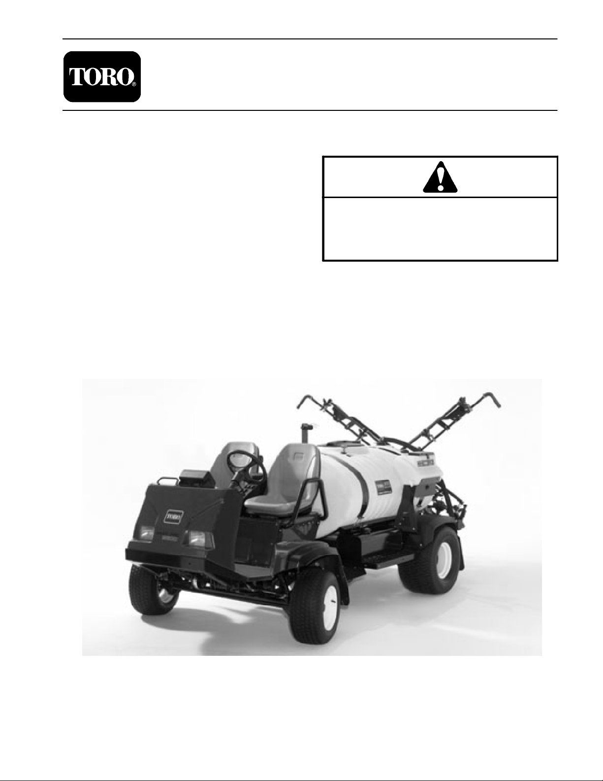
Multi Pro 5700--D.
REFER TO THE OPERATOR’S MANUAL FOR OPERATING, MAINTENANCE, AND ADJUSTMENT
INSTRUCTIONS. Space is provided in Chapter 2 of this
book to insert the Operator’s Manual and Parts Catalog
for your machine. Additional copies of the Operator’s
Manual and Parts Catalog are available on the internet
at www.Toro.com.
The Toro Company reserves the right to change product
specifications or this publication without notice.
Multi Pro
This safety symbol means DANGER, WARNING,
or CAUTION, PERSONAL SAFETY INSTRUCTION. When you see this symbol, carefully read
the instructions that follow. Failure to obey the
instructions may result in personal injury.
NOTE: A NOTE will give general information about the
correct operation, maintenance, service, testing, or repair of the machine.
IMPORTANT: The IMPORTANT notice will give important instructions which must be followed to prevent damage to systems or components on the
machine.
5700--D
R
E The Toro Company -- 2004, 2005, 2007, 2009, 2011
Page 2

This page is intentionally blank.
Multi Pro 5700--D
Page 3

Table Of Contents
Chapter 1 -- Safety
Safety Instructions 1 -- 2..........................
Jacking Instructions 1 -- 4.........................
Safety and Instruction Decals 1 -- 4................
Chapter 2 -- Product Records and Maintenance
Product Records 2 -- 1...........................
Equivalents and Conversions 2 -- 2................
Torque Specifications 2 -- 3.......................
Maintenance 2 -- 7...............................
Chapter 3 -- Kubota Diesel Engine
Introduction 3 -- 1................................
Specifications 3 -- 2..............................
Service and Repairs 3 -- 4........................
KUBOTA 05 SERIES ENGINE SERVICE MANUAL
Chapter 4 -- Hydraulic System
Specifications 4 -- 3..............................
General Information 4 -- 4........................
Hydraulic Schematic 4 -- 8........................
Hydraulic Flow Circuits 4 -- 9......................
Special Tools 4 -- 12.............................
Troubleshooting 4 -- 14...........................
Testing 4 - - 16...................................
Adjustments 4 -- 25..............................
Service and Repairs 4 -- 27.......................
EATON MODEL 26000 SINGLE GEAR PUMP REPAIR
INFORMATION
EATON MODEL 72400 SERVO CONTROLLED PIS-
TON PUMP REPAIR INFORMATION
EATON MODEL 74318 and 74348 PISTON MOTORS:
FIXED DISPLACEMENT, VALVE PLATE DESIGN
REPAIR INFORMATION
PARKER TORQLINK
TM
SERVICE PROCEDURE
Chapter 5 -- Electrical System
Electrical Diagrams 5 -- 2.........................
Special Tools 5 -- 3..............................
Troubleshooting 5 -- 4............................
Electrical System Quick Checks 5 -- 6..............
Component Testing 5 -- 7.........................
Service and Repairs 5 -- 27.......................
Chapter 6 -- Spray System
Specifications 6 -- 2..............................
General Information 6 -- 3........................
Spray System Flow Diagram 6 -- 4.................
Spray System Operation 6 -- 5....................
Troubleshooting 6 -- 6............................
Service and Repairs 6 -- 8........................
Chapter 7 -- Chassis
Specifications 7 -- 2..............................
Service and Repairs 7 -- 3........................
SafetyProduct Records
and Maintenance
Engine
Kubota Diesel
System
Hydraulic
System
Electrical
Spray
System
Multi Pro 5700--D
Chassis
Page 4

This page is intentionally blank.
Multi Pro 5700--D
Page 5

Table Of Contents (Continued)
Chapter 7.1 -- Sonic Boom System (Optional Kit)
General Information 7.1 -- 2......................
Special Tools 7.1 -- 3............................
Electrical Schematic 7.1 -- 4......................
Sonic Boom System Operation 7.1 -- 6.............
Troubleshooting 7.1 -- 16.........................
Service and Repairs 7.1 -- 22.....................
Chapter 8 -- Electrical Diagrams
System
Sonic BoomElectrical
Electrical Schematics 8 -- 3.......................
Circuit Diagrams 8 -- 6...........................
Wire Harness Drawings 8 -- 10....................
Drawings
Rev. DMulti Pro 5700--D
Page 6

This page is intentionally blank.
Rev. D
Multi Pro 5700--D
Page 7

Chapter 1
Table of Contents
SAFETY INSTRUCTIONS . . . . . . . . . . . . . . . . . . . . . . 2 JACKING INSTRUCTIONS
Before Operating . . . . . . . . . . . . . . . . . . . . . . . . . . . . 2
While Operating . . . . . . . . . . . . . . . . . . . . . . . . . . . . . 2
Maintenance and Service . . . . . . . . . . . . . . . . . . . . 3
SAFETY AND INSTRUCTION DECALS . . . . . . . . . .
Safety
. . . . . . . . . . . . . . . . . . . . . 4
4
Safety
Multi Pro 5700–D Page 1 – 1 Safety
Page 8

Safety Instructions
The Multi Pro 5700--D Turf Sprayer is designed and
tested to offer safe service when operated and maintained properly. Although hazard control and accident
prevention are partially dependent upon the design and
configuration of the machine, these factors are also dependent upon the awareness, concern, and proper
training of the personnel involved in the operation, transport, maintenance, and storage of the machine. Improper use or maintenance of the machine can result in injury
Before Operating
1. Read and understand the contents of the Operator’s
Manual before starting and operating the machine. Become familiar with the controls and know how to stop the
machine and engine quickly. Additional copies of the
Operator’s Manual are available on the internet at
www.Toro.com.
2. Keep all shields, safety devices, and decals in place.
If a shield, safety device, or decal is defective, illegible
or damaged, repair or replace it before operating the
machine. Also tighten any loose nuts, bolts or screws to
ensure machine is in safe operating condition.
3. Assure interlock switches are adjusted correctly so
engine cannot be started unless traction pedal is in the
NEUTRAL position.
or death. To reduce the potential for injury or death,
comply with the following safety instructions.
WARNING
To reduce the potential for injury or death,
comply with the following safety instructions.
4. Since diesel fuel is highly flammable, handle it carefully:
A. Store fuel in containers specifically designed for
this purpose.
B. Do not remove machine fuel tank cap while engine is hot or running.
C. Do not smoke while handling fuel.
D. Fill fuel tank outdoors and only to within an inch of
the top of the tank, not the filler neck. Do not overfill
the fuel tank.
E. Wipe up any spilled fuel.
While Operating
1. Sit on the seat when starting and operating the machine.
2. Before starting the engine:
A. Engage the parking brake.
B. Make sure traction pedal is in theNEUTRAL position and the pump switch is OFF.
3. Do not run engine in a confined area without adequate ventilation. Exhaust fumes are hazardous and
could possibly be deadly.
4. Do not touch engine, radiator, muffler or exhaust
pipe while engine is running or soon after it is stopped.
These areas could be hot enough to cause burns.
5. Before getting off the seat:
A. Ensure that traction pedal is in the NEUTRAL
position.
B. Set parking brake.
C. Turn pump switch OFF.
D. Stop engine and remove key from ignition switch.
E. Do not park on slopes unless wheels are chocked
or blocked.
6. Follow spray chemical manufacturer’s recommendations for handling precautions, protective equipment,
and mixing proportions.
Rev. C
Multi Pro 5700--DPage 1 -- 2Safety
Page 9

Maintenance and Service
1. Before servicing or making adjustments, turn spray
pump off, put traction pedal in neutral, stop engine, set
parking brake, and remove key from the switch.
2. Prior to servicing sprayer components, determine
what chemical(s) have been used in the sprayer. Follow
precautions and recommendations printed on chemical
container labels or Material Safety Data Sheets when
servicing sprayer components. Use appropriate protective equipment: protective clothing, chemical resistant
gloves, and eye protection.
3. Make sure machine is in safe operating condition by
keeping all nuts, bolts and screws tight.
4. Never store the machine or fuel container inside
where there is an open flame, such as near a water heater or furnace.
5. Make sure all hydraulic line connectors are tight and
that all hydraulic hoses and lines are in good condition,
before applying pressure to the system.
6. Keep body and hands away from pin hole leaks in hydraulic lines that eject high pressure hydraulic fluid. Use
cardboard or paper to find hydraulic leaks. Hydraulic
fluid escaping under pressure can penetrate skin and
cause injury. Fluid accidentally injected into the skin
must be surgically removed within a few hours by a doctor familiar with this form of injury or gangrene may result.
10.If engine must be running to perform maintenance or
an adjustment, keep clothing, hands, feet, and other
parts of the body away from moving parts. Keep bystanders away.
11. Do not overspeed the engine. To assure safety and
accuracy, check maximum engine speed.
12.Shut engine off before checking or adding oil to the
crankcase.
13.Disconnect battery before servicing the machine.
Disconnect negative (–) battery cable first and positive
(+) cable last. If battery voltage is required for troubleshooting or test procedures, temporarily connect the
battery. Reconnect positive (+) cable first and negative
(–) cable last.
14.Battery acid is poisonous and can cause burns.
Avoid contact with skin, eyes, and clothing. Protect your
face, eyes, and clothing when working with a battery.
15.Battery gases can explode. Keep cigarettes, sparks,
and flames away from the battery.
16.To assure optimum performance and continued
safety of the machine, use genuine Toro replacement
parts and accessories. Replacement parts and accessories made by other manufacturers may result in nonconformance with safety standards, and the warranty
may be voided.
Safety
7. Before disconnecting or performing any work on the
hydraulic system, all pressure in hydraulic system must
be relieved. To relieve system pressure, rotate steering
wheel in both directions after the key switch has been
turned off.
8. If major repairs are ever needed or assistance is desired, contact an Authorized Toro Distributor.
9. To reduce potential fire hazard, keep engine area
free of excessive grease, grass, leaves and dirt. Clean
protective screen on machine frequently.
17.When raising the machine to change tires or to perform other service, use correct blocks, hoists, and jacks.
Make sure machine is parked on a solid level surface
such as a concrete floor. Prior to raising the machine, remove any attachments that may interfere with the safe
and proper raising of the machine. Always chock or
block wheels. Use jack stands or solid wood blocks to
support the raised machine. If the machine is not properly supported by blocks or jack stands, the machine
may move or fall, which may result in personal injury
(see Jacking Instructions in this Chapter).
Multi Pro 5700–D Page 1 – 3 Safety
Page 10
Jacking Instructions
CAUTION
When raising the machine to change tires or to
perform other service, use correct blocks,
hoists, and jacks. Make sure machine is parked
on a solid level surface such as a concrete floor.
Prior to raising machine, remove any attachments that may interfere with the safe and proper
raising of the machine. Always chock or
block wheels. Use jack stands or solid wood
blocks to support the raised machine. If the machine is not properly supported by blocks or
jack stands, the machine may move or fall,
which may result in personal injury.
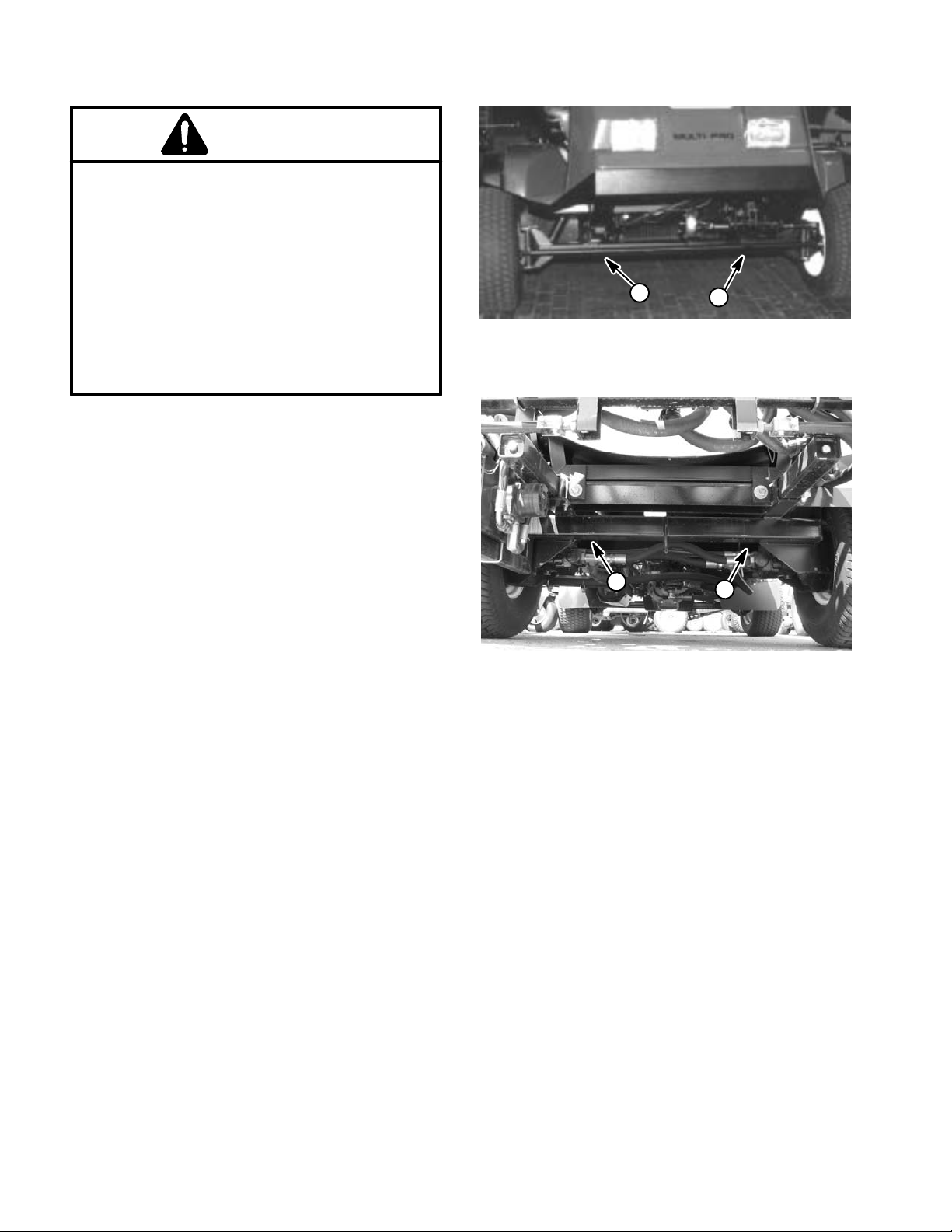
Jacking the Front End
1. Set parking brake and chock both rear tires to prevent the machine from moving.
2. Position jack securely under the front axle, directly
beneath the leaf springs (Fig. 1).
1
Figure 1
1. Front jacking points
1
3. Jack front of machine off the ground.
4. Position jack stands or hardwood blocks under the
axle as c
chine.
Jacking the Rear End
1. Set parking brake and chock both front tires to prevent the machine from moving.
2. Place jack securely under the rear most frame supports between the angle welds (Fig. 2).
3. Jack rear of machine off the ground.
4. Position jack stands or hardwood blocks under the
frame to support the machine.
lose to the wheel as possible to support the ma-
Safety and Instruction Decals
Numerous safety and instruction decals are affixed to
the Multi Pro 5700–D. If any decal becomes illegible or
damaged, install a new decal. Part numbers are listed
in your Parts Catalog. Order replacement decals from
your Authorized Toro Distributor.
1
Figure 2
1. Rear jacking points
1
Safety Page 1 – 4 Multi Pro 5700–D
Page 11

Product Records and Maintenance
Table of Contents
PRODUCT RECORDS 1.........................
EQUIVALENTS AND CONVERSIONS 2...........
Decimal and Millimeter Equivalents 2............
U.S. to Metric Conversions 2...................
TORQUE SPECIFICATIONS 3....................
Fastener Identification 3.......................
Standard Torque for Dry, Zinc Plated and
Steel Fasteners (Inch Series Fasteners) 4......
Standard Torque for Dry, Zinc Plated and
Steel Fasteners (Metric Fasteners) 5...........
Other Torque Specifications 6..................
Conversion Factors 6..........................
MAINTENANCE 7...............................
Product Records
Chapter 2
Product Records
and Maintenance
Insert Operator’s Manual and Parts Catalog for your
Multi Pro 5700--D at the end of this chapter. Additionally,
if any optional equipment has been installed to your
sprayer, insert the Installation Instructions, Operator’s
Manuals and Parts Catalogs for those options at the end
of this chapter.
Multi Pro 5700--D
Page 2 -- 1
Product Records and Maintenance
Page 12
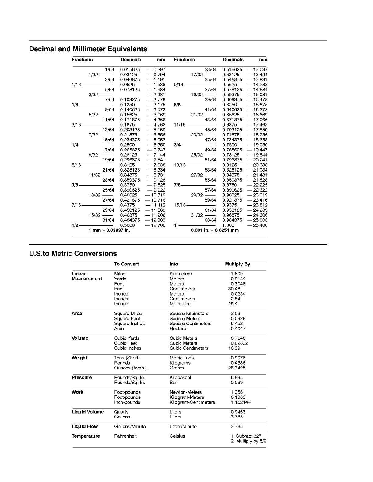
Equivalents and Conversions
0.09375
Product Records and Maintenance
Page 2 -- 2
Rev. C
Multi Pro 5700--D
Page 13
Torque Specifications
Recommended fastener torque values are listed in the
following tables. For critical applications, as determined
by Toro, either the recommended torque or a torque that
is unique to the application is clearly identified and specified in this Service Manual.
These Torque Specifications for the installation and
tightening of fasteners shall apply to all fasteners which
do not have a specific requirement identified in this Service Manual. The following factors shall be considered
when applying torque: cleanliness of the fastener, use
of a thread sealant (e.g. Loctite), degree of lubrication
on the fastener, presence of a prevailing torque feature,
hardness of the surface underneath the fastener’s head,
or similar condition which affects the installation.
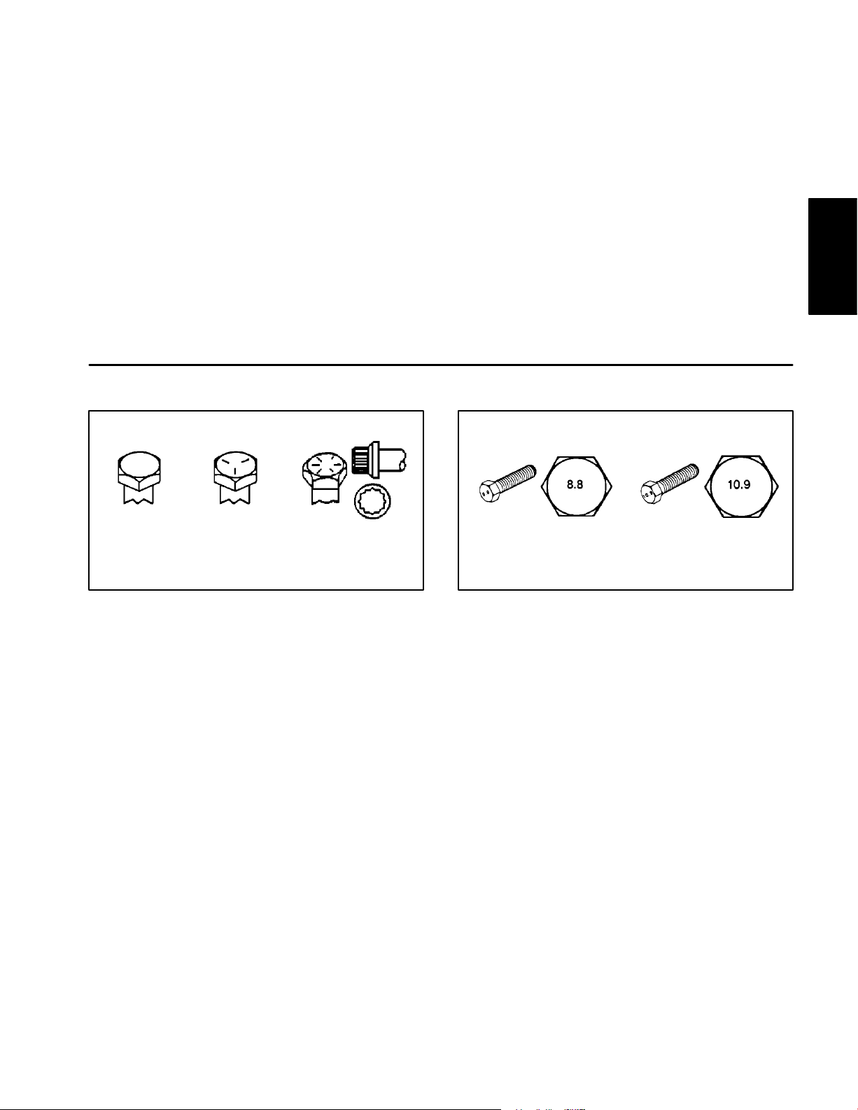
Fastener Identification
As noted in the following tables, torque values should be
reduced by 25% for lubricated fasteners to achieve
the similar stress as a dry fastener. Torque values may
also have to be reduced when the fastener is threaded
into aluminum or brass. The specific torque value
should be determined based on the aluminum or brass
material strength, fastener size, length of thread engagement, etc.
The standard method of verifying torque shall be performed by marking a line on the fastener (head or nut)
and mating part, then back off fastener 1/4 of a turn.
Measure the torque required to tighten the fastener until
the lines match up.
Product Records
and Maintenance
Grade 1
Grade 5 Grade 8
Inch Series Bolts and Screws
Figure 1 Figure 2
Class 8.8 Class 10.9
Metric Bolts and Screws
Multi Pro 5700–D
Page 2 – 3
Product Records and Maintenance
Page 14
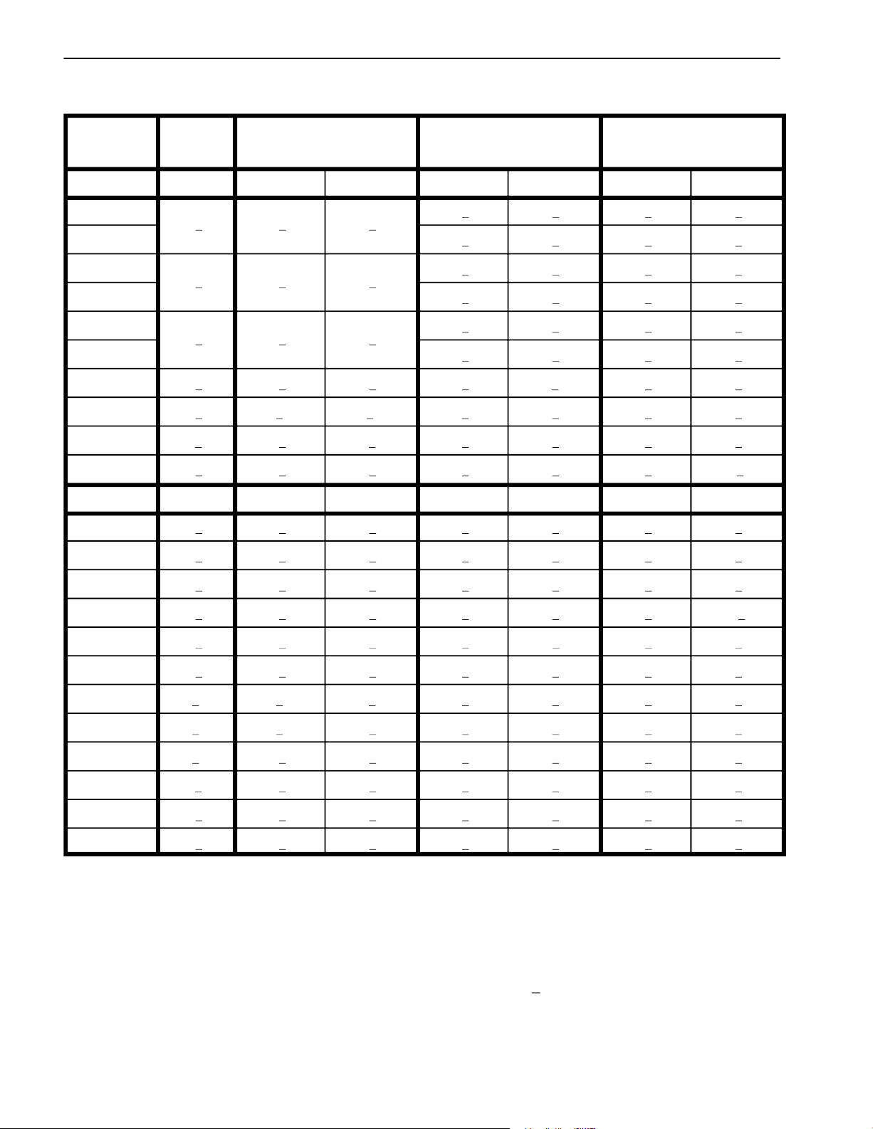
Standard Torque for Dry, Zinc Plated and Steel Fasteners (Inch Series Fasteners)
Grade 1, 5, &
Thread Size
# 6 – 32 UNC
# 6 – 40 UNF 17 + 2 190 + 20 25 + 2 280 + 20
# 8 – 32 UNC
# 8 – 36 UNF 31 + 3 350 + 30 43 + 4 485 + 45
# 10 – 24 UNC
# 10 – 32 UNF 48 + 4 540 + 45 68 + 6 765 + 70
1/4 – 20 UNC 48 + 7 53 + 7 599 + 79 100 + 10 1125 + 100 140 + 15 1580 + 170
1/4 – 28 UNF 53 + 7 65 + 10 734 + 113 115 + 10 1300 + 100 160 + 15 1800 + 170
5/16 – 18 UNC 115 + 15 105 + 17 1186 + 169 200 + 25 2250 + 280 300 + 30 3390 + 340
5/16 – 24 UNF 138 + 17 128 + 17 1446 + 192 225 + 25 2540 + 280 325 + 30 3670 + 340
3/8 – 16 UNC 16 + 2 16 + 2 22 + 3 30 + 3 41 + 4 43 + 4 58 + 5
8 with Thin
Height Nuts
in–lb in–lb N–cm in–lb N–cm in–lb N–cm
+ 2 10 + 2
13 + 2
+ 2
+ 2 18 + 2
ft–lb ft–lb N–m ft–lb N–m ft–lb N–m
SAE Grade 1 Bolts, Screws, Studs, &
Sems with Regular Height Nuts
(SAE J995 Grade 2 or Stronger Nuts)
+ 2 13 + 2
25 + 5
+ 5
+ 5 30 + 5
+ 23 147 + 23
282 + 30
+ 30
+ 56 339 + 56
SAE Grade 5 Bolts, Screws, Studs, &
Sems with Regular Height Nuts
(SAE J995 Grade 2 or Stronger Nuts)
15 + 2 170 + 20 23 + 2 260 + 20
29 + 3 330 + 30 41 + 4 460 + 45
42 + 4 475 + 45 60 + 6 675 + 70
SAE Grade 8 Bolts, Screws, Studs, &
Sems with Regular Height Nuts
(SAE J995 Grade 5 or Stronger Nuts)
3/8 – 24 UNF 17 + 2 18 + 2 24 + 3 35 + 3 47 + 4 50 + 4 68 + 5
7/16 – 14 UNC 27 + 3 27 + 3 37 + 4 50 + 5 68 + 7 70 + 7 95 + 9
7/16 – 20 UNF 29 + 3 29 + 3 39 + 4 55 + 5 75 + 7 77 + 7 104 + 9
1/2 – 13 UNC 30 + 3 48 + 7 65 + 9 75 + 8 102 + 11 105 + 10 142 + 14
1/2 – 20 UNF 32 + 3 53 + 7 72 + 9 85 + 8 115 + 11 120 + 10 163 + 14
5/8 – 11 UNC 65 + 10 88 + 12 119 + 16 150 + 15 203 + 20 210 + 20 285 + 27
5/8 – 18 UNF 75 + 10 95 + 15 129 + 20 170 + 15 230 + 20 240 + 20 325 + 27
3/4 – 10 UNC 93 + 12 140 + 20 190 + 27 265 + 25 359 + 34 375 + 35 508 + 47
3/4 – 16 UNF 115 + 15 165 + 25 224 + 34 300 + 25 407 + 34 420 + 35 569 + 47
7/8 – 9 UNC 140 + 20 225 + 25 305 + 34 430 + 45 583 + 61 600 + 60 813 + 81
7/8 – 14 UNF 155 + 25 260 + 30 353 + 41 475 + 45 644 + 61 660 + 60 895 + 81
NOTE: Reduce torque values listed in the table above
by 25% for lubricated fasteners. Lubricated fasteners
on the fastener size, the aluminum or base material
strength, length of thread engagement, etc.
are defined as threads coated with a lubricant such as
oil, graphite, or thread sealant such as Loctite.
NOTE: The nominal torque values listed above for
Grade 5 and 8 fasteners are based on 75% of the miniNOTE: Torque values may have to be reduced when
installing fasteners into threaded aluminum or brass.
The specific torque value should be determined based
mum proof load specified in SAE J429. The tolerance is
approximately +
10% of the nominal torque value. Thin
height nuts include jam nuts.
Product Records and Maintenance
Page 2 – 4
Multi Pro 5700–D
Page 15
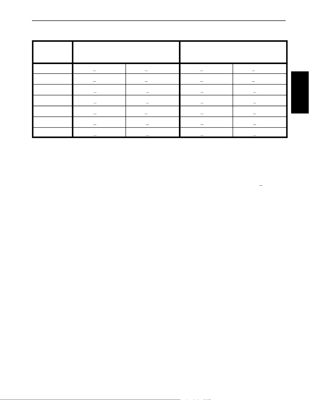
Standard Torque for Dry, Zinc Plated and Steel Fasteners (Metric Fasteners)
Class 8.8 Bolts, Screws, and Studs with Class 10.9 Bolts, Screws, and Studs with
Thread Size
Size
Regular Height Nuts
(Class 8 or Stronger Nuts) (Class 10 or Stronger Nuts)
Height Nuts
Regular Height Nuts
Height Nuts
M5 X 0.8
M6 X 1.0
M8 X 1.25
M10 X 1.5
M12 X 1.75
M16 X 2.0
M20 X 2.5
NOTE: Reduce torque values listed in the table above
by 25% for lubricated fasteners. Lubricated fasteners
are defined as threads coated with a lubricant such as
oil, graphite, or thread sealant such as Loctite.
NOTE: Torque values may have to be reduced when
installing fasteners into threaded aluminum or brass.
The specific torque value should be determined based
57 + 5 in–lb 640 + 60 N–cm 78 + 7 in–lb 885 + 80 N–cm
96 + 9 in–lb 1018 + 100 N–cm 133 + 13 in–lb 1500 + 150 N–cm
19 + 2 ft–lb 26 + 3 N–m 27 + 2 ft–lb 36 + 3 N–m
38 + 4 ft–lb 52 + 5 N–m 53 + 5 ft–lb 72 + 7 N–m
66 + 7 ft–lb 90 + 10 N–m 92 + 9 ft–lb 125 + 12 N–m
166 + 15 ft–lb 225 + 20 N–m 229 + 22 ft–lb 310 + 30 N–m
325 + 33 ft–lb 440 + 45 N–m 450 + 37 ft–lb 610 + 50 N–m
on the fastener size, the aluminum or base material
strength, length of thread engagement, etc.
NOTE: The nominal torque values listed above are
based on 75% of the minimum proof load specified in
SAE J1199. The tolerance is approximately +
nominal torque value.
10% of the
Product Records
and Maintenance
Multi Pro 5700–D
Page 2 – 5
Product Records and Maintenance
Page 16
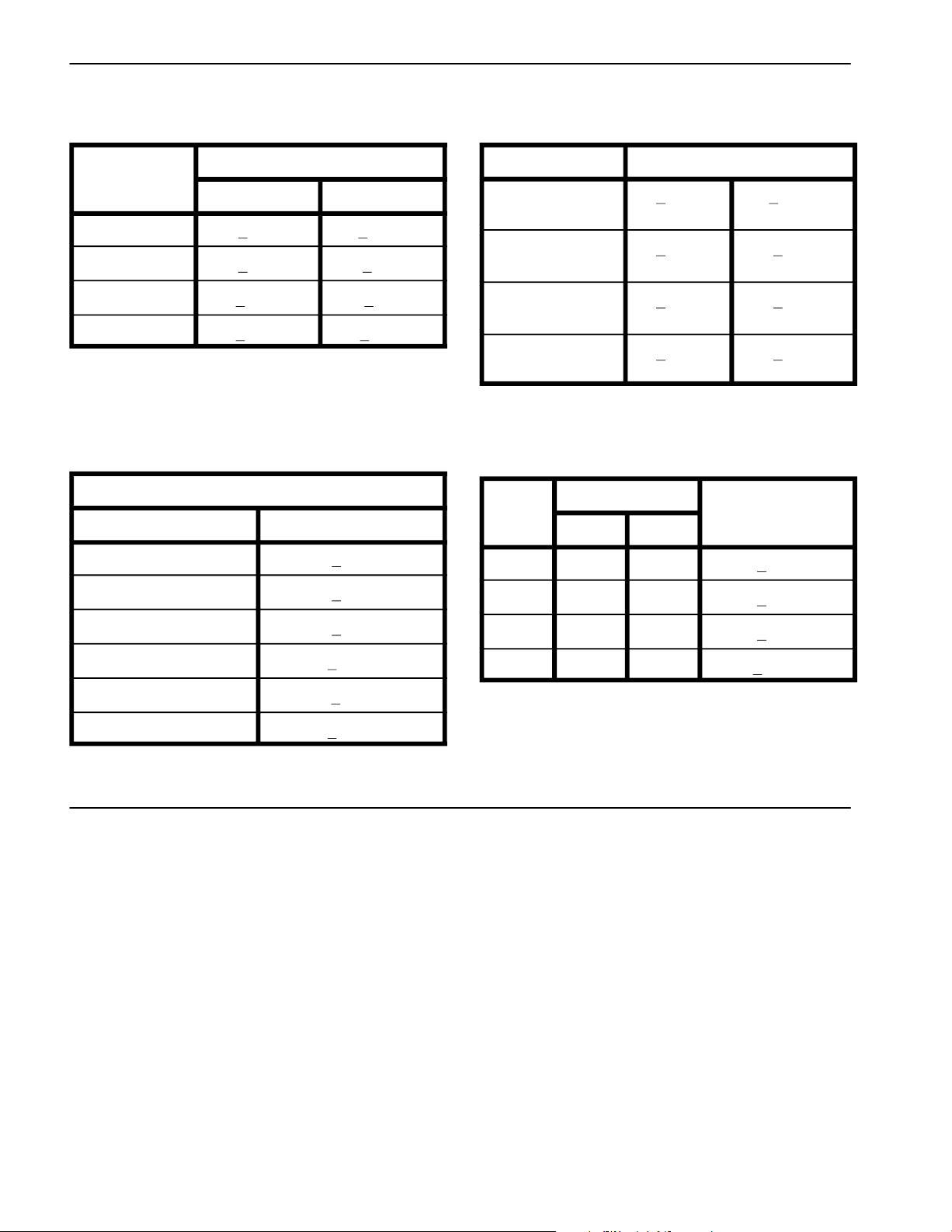
Other Torque Specifications
SAE Grade 8 Steel Set Screws Wheel Bolts and Lug Nuts
Recommended Torque
Size Thread Size
Square Head Hex Socket
1/4 – 20 UNC 140 + 20 in–lb 73 + 12 in–lb
5/16 – 18 UNC 215 + 35 in–lb 145 + 20 in–lb
3/8 – 16 UNC 35 + 10 ft–lb 18 + 3 ft–lb
1/2 – 13 UNC 75 + 15 ft–lb 50 + 10 ft–lb
Thread Cutting Screws
(Zinc Plated Steel)
Type 1, Type 23, or Type F
Thread Size Baseline Torque*
No. 6 – 32 UNC 20 + 5 in–lb
No. 8 – 32 UNC 30 + 5 in–lb
Thread Size
7/16 – 20 UNF
Grade 5
1/2 – 20 UNF
Grade 5
M12 X 1.25
Class 8.8
M12 X 1.5
Class 8.8
** For steel wheels and non–lubricated fasteners.
Thread Cutting Screws
(Zinc Plated Steel)
Thread
Size
No. 6 18 20 20 + 5 in–lb
No. 8 15 18 30 + 5 in–lb
Threads per Inch
Type A Type B
Recommended Torque**
65 + 10 ft–lb 88 + 14 N–m
80 + 10 ft–lb 108 + 14 N–m
80 + 10 ft–lb 108 + 14 N–m
80 + 10 ft–lb 108 + 14 N–m
Torque* Baseline Torque*
No. 10 – 24 UNC 38 + 7 in–lb
1/4 – 20 UNC 85 + 15 in–lb
5/16 – 18 UNC 110 + 20 in–lb
3/8 – 16 UNC 200 + 100 in–lb
Conversion Factors
in–lb X 11.2985 = N–cm N–cm X 0.08851 = in–lb
ft–lb X 1.3558 = N–m N–m X 0.7376 = ft–lb
No. 10 12 16 38 + 7 in–lb
No. 12 11 14 85 + 15 in–lb
* Hole size, material strength, material thickness & finish
must be considered when determining specific torque
values. All torque values are based on non–lubricated
fasteners.
Product Records and Maintenance
Page 2 – 6
Multi Pro 5700–D
Page 17

Maintenance
Maintenance procedures and recommended service intervals for the Multi Pro 5700–D are covered in the Operator’s Manual. Refer to that publication when performing
regular equipment maintenance. Several maintenance
procedures have break–in intervals identified in the Operator’s Manual. Refer to the Engine Operator’s Manual
for additional engine specific maintenance procedures.
Product Records
and Maintenance
Multi Pro 5700–D
Page 2 – 7
Product Records and Maintenance
Page 18

This page is intentionally blank.
Product Records and Maintenance
Page 2 – 8
Multi Pro 5700–D
Page 19

Table of Contents
INTRODUCTION . . . . . . . . . . . . . . . . . . . . . . . . . . . . . . 1
SPECIFICATIONS 2
SERVICE AND REPAIRS . . . . . . . . . . . . . . . . . . . . . . 4
Fuel System
Air Cleaner
Exhaust System
Radiator 10
Engine 12. . . . . . . . . . . . . . . . . . . . . . . . . . . . . . . . . . . .
KUBOTA 05 SERIES ENGINE SERVICE MANUAL
. . . . . . . . . . . . . . . . . . . . . . . . . . . . . . . . . .
. . . . . . . . . . . . . . . . . . . . . . . . . . . .
. . . . . . . . . . . . . . . . . . . . . . . . . . . . . . . . 4
. . . . . . . . . . . . . . . . . . . . . . . . . . . . . . . . . 6
. . . . . . . . . . . . . . . . . . . . . . . . . . . . 8
Introduction
This Chapter gives information about specifications, adjustments and repair of the Kubota Diesel engine that
powers the Multi Pro 5700–D.
Chapter 3
Kubota Diesel Engine
Engine
Kubota Diesel
General maintenance procedures are described in your
Operator’s Manual. Information on engine troubleshooting, testing, disassembly and reassembly is identified in
the Kubota 05 Series Engine Service Manual that is included at the end of this section.
Most engine repairs and adjustments require tools
which are commonly available in many service shops.
Special tools are described in the Kubota 05 Series Engine Service Manual. The use of some specialized test
equipment is explained. However, the cost of the test
equipment and the specialized nature of some repairs
may dictate that the work be done at an engine repair
facility.
Multi Pro 5700–D Page 3 – 1 Kubota Diesel Engine
Page 20

Specifications
Item Description
Make / Designation
Horse Power 35.5 HP @ 3000 RPM
Bore mm (in.) 78.0 (3.07)
Stroke mm (in.) 78.4 (3.09)
Total Displacement
Torque
N–m (ft–lb) 84 (62) @ 3000 RPM
Firing Order 1 – 3 – 4 – 2
Fuel No. 2 Diesel Fuel (ASTM D975)
Fuel Injection Pump
Governor Centrifugal Mechanical
Low Idle (no load) 1200 – 1250 RPM
High Idle (no load) 3050 – 3150 RPM
Direction of Rotation
cc (cu. in.) 1498 (91)
V1505–EB–TORO, Kubota, 4–Cycle, 4 Cylinder,
Water Cooled, Diesel Engine
Bosch MD Type Mini Pump
Counterclockwise (Viewed from Flywheel)
Compression Ratio 23:1
Injection Nozzles Mini Nozzle (DN–OPD)
Engine Oil 10W30 Detergent (API CD or better)
Oil Pump
Crankcase Oil Capacity liters (U.S. qt.) 4.7 (5) with Filter
Starter 12 VDC, 1 KW
Alternator/Regulator 12 VDC 40 AMP
Dry Weight 110
kilograms (U.S. lbs) (242.5)
Trochoid Type
Kubota Diesel Engine
Page 3 – 2
Multi Pro 5700–D
Page 21

This page is intentionally blank.
Engine
Kubota Diesel
Multi Pro 5700–D Page 3 – 3 Kubota Diesel Engine
Page 22
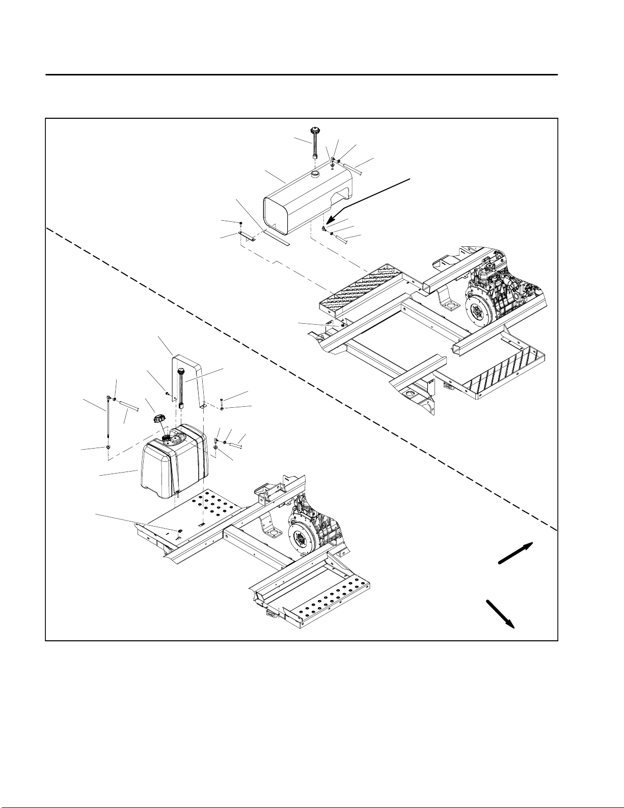
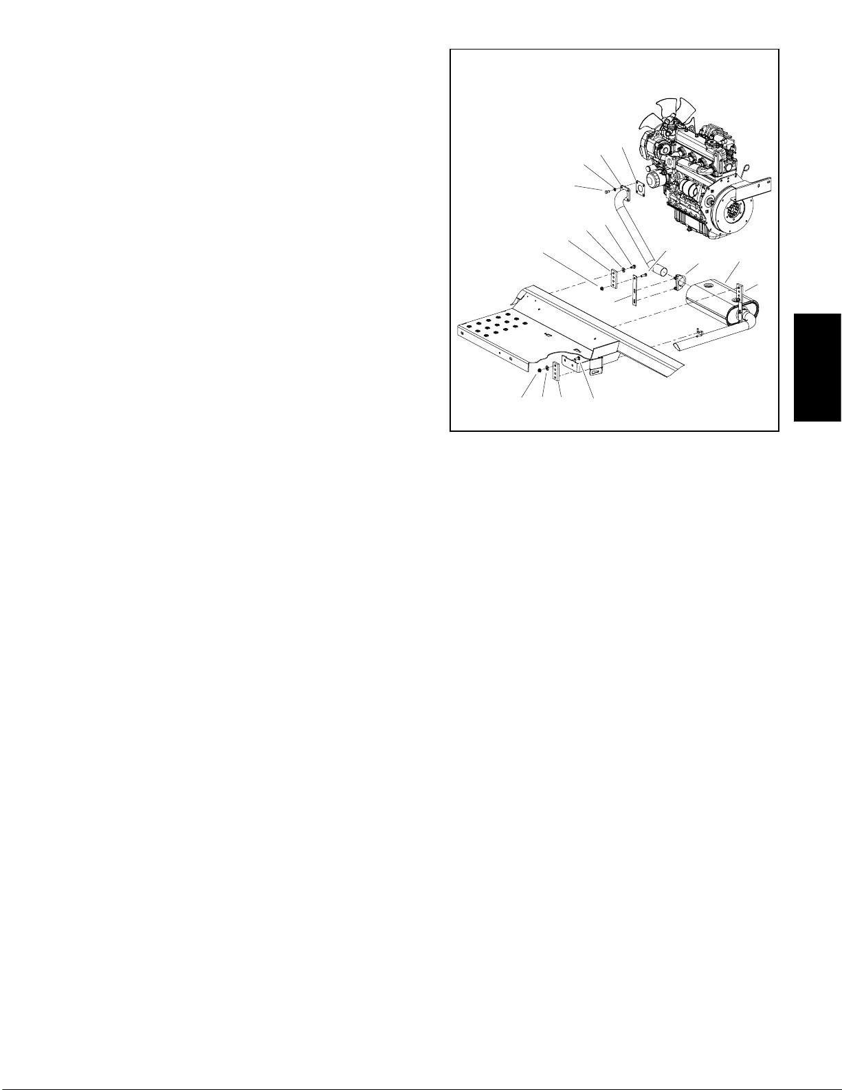
Service and Repairs
Fuel System
SERIAL NUMBER BELOW 310000000
12
11
10
19
18
15
23
14
20
21
22
14
13
17
1
16
2
4
3
5
6
Thread Sealant
7
5
8
9
24
25
26
SERIAL NUMBER ABOVE 310000000
1. Fuel tank
2. Fuel cap with gauge
3. Bushing
4. Elbow fitting
5. Hose clamp
6. Fuel return hose
7. Elbow fitting
8. Fuel supply hose
9. Flange nut (4 used)
24
Figure 1
10. Hold down strap (2 used)
11. Flange head screw (4 used)
12. Cushion strip (2 used)
13. Fuel return hose
14. Hose clamp
15. Elbow fitting
16. Flat washer (2 used)
17. Cap screw (2 used)
18. Fuel gauge
FRONT
RIGHT
19. Tank strap (2 used)
20. Washer head screw (2 used)
21. Fuel tank cap
22. Fuel supply hose
23. Standpipe (fuel supply)
24. Grommet
25. Fuel tank
26. U -- nut (2 used)
Kubota Diesel Engine
Page 3 -- 4
Rev. D
Multi Pro 5700--D
Page 23
DANGER
Because diesel fuel is highly flammable, use
caution when storing or handling it. Do not
smoke while filling the fuel tank. Do not fill fuel
tank while engine is running, hot or when machine is in an enclosed area. Always fill fuel tank
outside and wipe up any spilled fuel before starting the engine. Store fuel in a clean, safety--approved container and keep cap in place. Use diesel fuel for the engine only; not for any other
purpose.
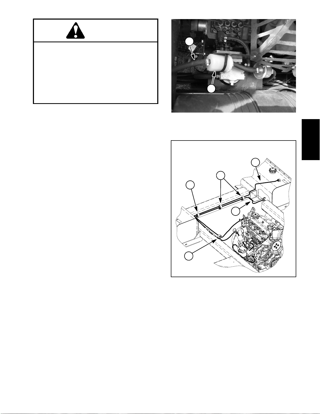
Check Fuel Lines and Connections
Check fuel lines and connections periodically as recommended in the Operator’s Manual. Check lines for deterioration, damage, leaks or loose connections. Replace
hoses, clamps and connections as necessary.
Empty and Clean Fuel Tank
Empty and clean the fuel tank if the fuel system becomes contaminated or if the machine is to be stored for
an extended period.
To clean fuel tank, flush tank out with clean solvent.
Make sure tank is free of contaminates and debris.
2
1
SERIAL NUMBER BELOW 310000000
Figure 2
1. Fuel filter 2. Fuel hose (from tank)
SERIAL NUMBER ABOVE 310000000
2
3
3
Engine
Kubota Diesel
Fuel Tank Removal
1. Park machine on a level surface, stop engine, engage parking brake and remove key from the ignition
switch.
2. Use a fuel transfer pump to remove fuel from the fuel
tank and into a suitable container.
3. Loosen hose clamps that secure supply and return
hoses to tank. Remove hoses from tank.
4. Remove fuel tank from machine using Figure 1 as a
guide.
5. If necessary, remove fuel hoses from machine. Note
fuel hose routing for assembly purposes (Fig. 3).
Fuel Tank Installation
1. Install fuel tank tomachine using Figure 1 as a guide.
2. If fuel hoses were removed, route fuel hoses through
R--clamps on frame and connect to proper engine and
fuel tank fittings. Secure hoses with hose clamps.
3
1. Fuel supply hose
2. Fuel return hose
1
Figure 3
3. R--clamp
3. Fill fuel tank (see Operator’s Manual).
4. Start engine and check fuel line connections for any
leakage.
Multi Pro 5700--D Page 3 -- 5 Kubota Diesel Engine
Rev. D
Page 24
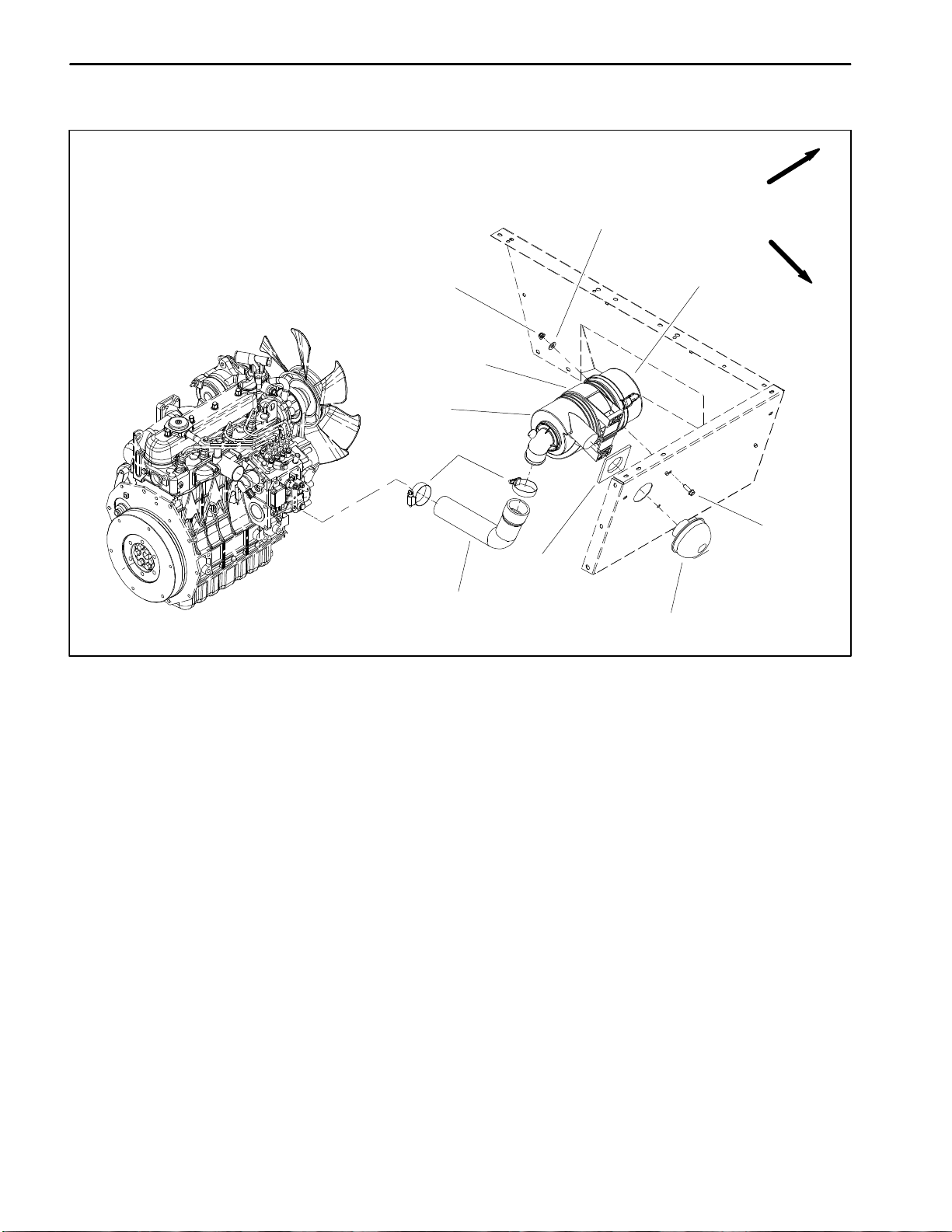
Air Cleaner
FRONT
4
RIGHT
1. Air cleaner housing
2. Mounting band
3. Flange nut (2 used)
4. Flat washer (2 used)
3
2
1
10
9
Figure 4
5. Air cleaner cover
6. Flange head screw (2 used)
7. Air cleaner cap
5
6
8
7
8. Foam seal
9. Air cleaner hose
10. Hose clamp
Kubota Diesel Engine
Page 3 – 6
Multi Pro 5700–D
Page 25
Removal (Fig. 4)
NOTE: For air cleaner maintenance information, refer
to the Operator’s Manual.
1. Raise passenger seat to access air cleaner assembly.
2. Remove air cleaner components as needed using
Figure 4 as a guide.
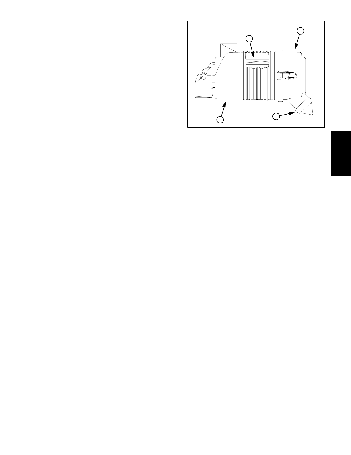
Installation (Fig. 4)
IMPORTANT: Any leaks in the air filter system will
cause serious engine damage. Make sure that all air
cleaner components are in good condition and are
properly secured during reassembly.
1. Assemble air cleaner system using Figures 4 as a
guide. Make sure that vacuator valve on air cleaner cover points downward after assembly (Fig. 5).
3
2
1
4
Figure 5
1. Air cleaner housing 3. Air cleaner cover
2. Air cleaner element 4. Vacuator valve
Engine
Kubota Diesel
Multi Pro 5700–D Page 3 – 7 Kubota Diesel Engine
Page 26
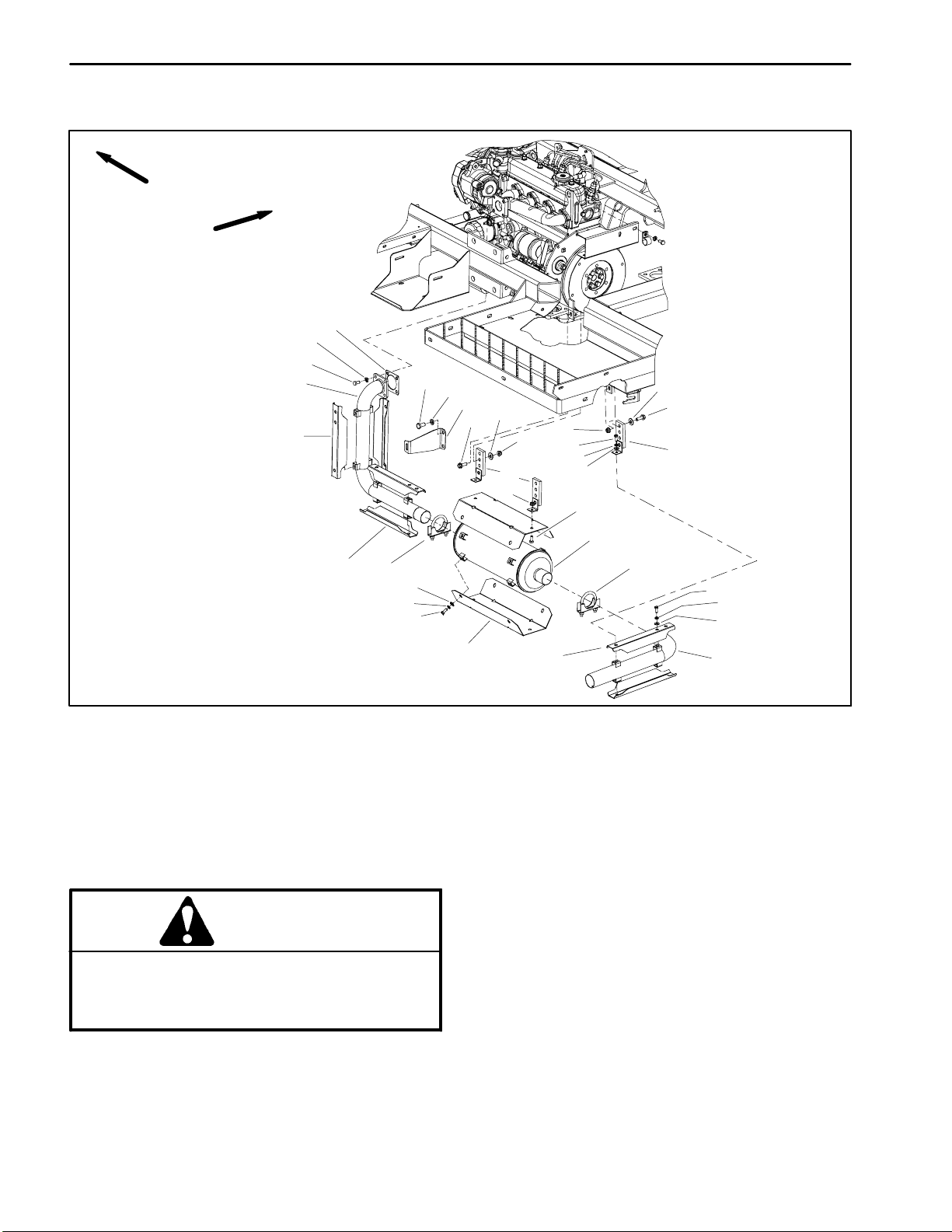
Exhaust System
FRONT
RIGHT
1
2
3
4
5
6
7
8
10
9
12
16
11
11
13
14
15
17
18
10
9
12
5
19
SERIAL NUMBER BELOW 310000000
1. Muffler gasket
2. Lock washer (4 used)
3. Cap screw (4 used)
4. Exhaust pipe
5. Heat shield (6 used)
6. Cap screw (2 used)
7. Lock washer (2 used)
8. Exhaust pipe bracket
9. Flange head screw
10. Flat washer
11. Flange nut
12. Exhaust pipe hanger
13. Cap screw
14. Lock washer
Removal (Fig. 6 or 7)
CAUTION
The muffler and exhaust pipes may be hot. T o
avoid possible burns, allow the engine and exhaust system to cool before working on the exhaust system.
15
14
13
19
13
14
15
21
5
20
Figure 6
15. Flat washer
16. Flange nut
17. Cap screw
18. Muffler
19. Muffler clamp
20. Tailpipe
21. Muffler heat shield (2 used)
3. Remove exhaust system components as required
using Fig. 6 (machines with serial number below
310000000) or Fig. 7 (machines with serial number
above 310000000) as a guide. During removal, note
location of fasteners in rubber exhaust system hangers
so hangers are properly assembled.
NOTE: On machines with serial number below
310000000, the muffler inlet is offset and the muffler out-
let is centered.
1. Park machine on a level surface, stop engine, engage parking brake and remove key from the ignition
switch.
2. Support muffler from below to prevent it from falling.
Kubota Diesel Engine
Page 3 -- 8
4. Locate and retrieve muffler gasket if exhaust pipe
was removed.
5. Remove heat shields, hangers and brackets from
exhaust components as needed.
Rev. D
Multi Pro 5700--D
Page 27
Installation (Fig. 6 or 7)
1. Install all removed heat shields, hangers and brackets to exhaust components.
SERIAL NUMBER ABOVE 310000000
2. Make sure that gasket surfaces on engine exhaust
manifold and exhaust pipe are clean.
NOTE: On machines with serial number below
310000000, the muffler inlet is offset and the muffler outlet is centered.
3. Install all removed exhaust system components using Fig. 6 (machines with serial number below
310000000) or Fig. 7 (machines with serial number
above 310000000) as a guide.
A. During exhaust installation, finger tighten all exhaust system components before fully tightening
any of the fasteners.
B. Install rubber exhaust system hangers as noted
during exhaust system removal.
C. Make sure that tailpipe outlet is parallel to the
ground.
D. Tighten muffler clamps last to secure exhaust
components.
2
3
6
7
8
13
6
7
1. Muffler gasket
2. Lock washer (4 used)
3. Cap screw (4 used)
4. Exhaust pipe
5. Screw (2 used)
6. Flat washer (3 used)
7. Muffler hanger (3 used)
1
4
5
9
10
14
Figure 7
8. Flange nut (2 used)
9. Cap screw (2 used)
10. Muffler hanger (2 used)
11. Muffler clamp (2 used)
12. Muffler
13. Flange nut
14. Carriage screw
11
12
7
Engine
Kubota Diesel
Multi Pro 5700--D Page 3 -- 9 Kubota Diesel Engine
Rev. D
Page 28
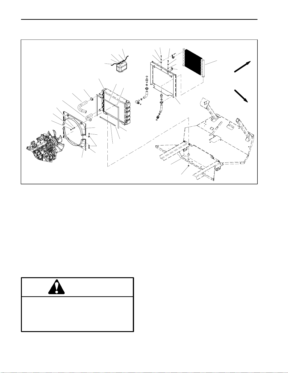
Radiator
19
4
18
17
16
15
14
20
10
22
6
7
8
9
8
4
3
5
4
3
2
1
FRONT
13
12
11
24
RIGHT
18
21
20
1. Oil cooler
2. Radiator brace (2 used)
3. Flat washer
4. Lock washer
5. Cap screw (2 used)
6. Cap screw (4 used)
7. Overflow hose
8. Hose clamp
9. Overflow bottle
23
13
10. Hose
11. Radiator shroud
12. Foam seal (2 used)
13. Foam seal
14. Radiator
15. Hose clamp
16. Upper radiator hose
17. Lower radiator hose
18. Flat washer
Removal (Figs. 7)
1. Park machine on a level surface, stop engine, engage parking brake and remove key from the ignition
switch. Raise seats of machine to allow access to engine compartment.
CAUTION
Do not open radiator cap or drain coolant if the
radiator or engine is hot. Pressurized, hot coolant can escape and cause burns. Ethylene–glycol antifreeze is poisonous. Dispose of coolant
properly, or store it in a properly labeled container away from children and pets.
25
26
Figure 7
19. Cap screw (4 used)
20. Fan shroud
21. Flange nut
22. Cap screw (2 used)
23. Foam seal (2 used)
24. Foam seal (2 used)
25. Isomount (2 used)
26. Flange nut (2 used)
2. Drain radiator into a suitable container using the ra-
diator drain (see Operator’s Manual).
3. Loosen hose clamps that secure radiator hoses. Dis-
connect upper and lower hoses from the radiator.
4. Loosen hose clamp that secures overflow hose to ra-
diator flange (Fig. 9). Slide overflow hose from radiator
flange and position hose away from radiator.
5. Remove six (6) cap screws (items 5 and 6), lock
washers and flat washers that secure top and bottom of
radiator shroud to radiator.
Kubota Diesel Engine
Page 3 – 10
Multi Pro 5700–D
Page 29
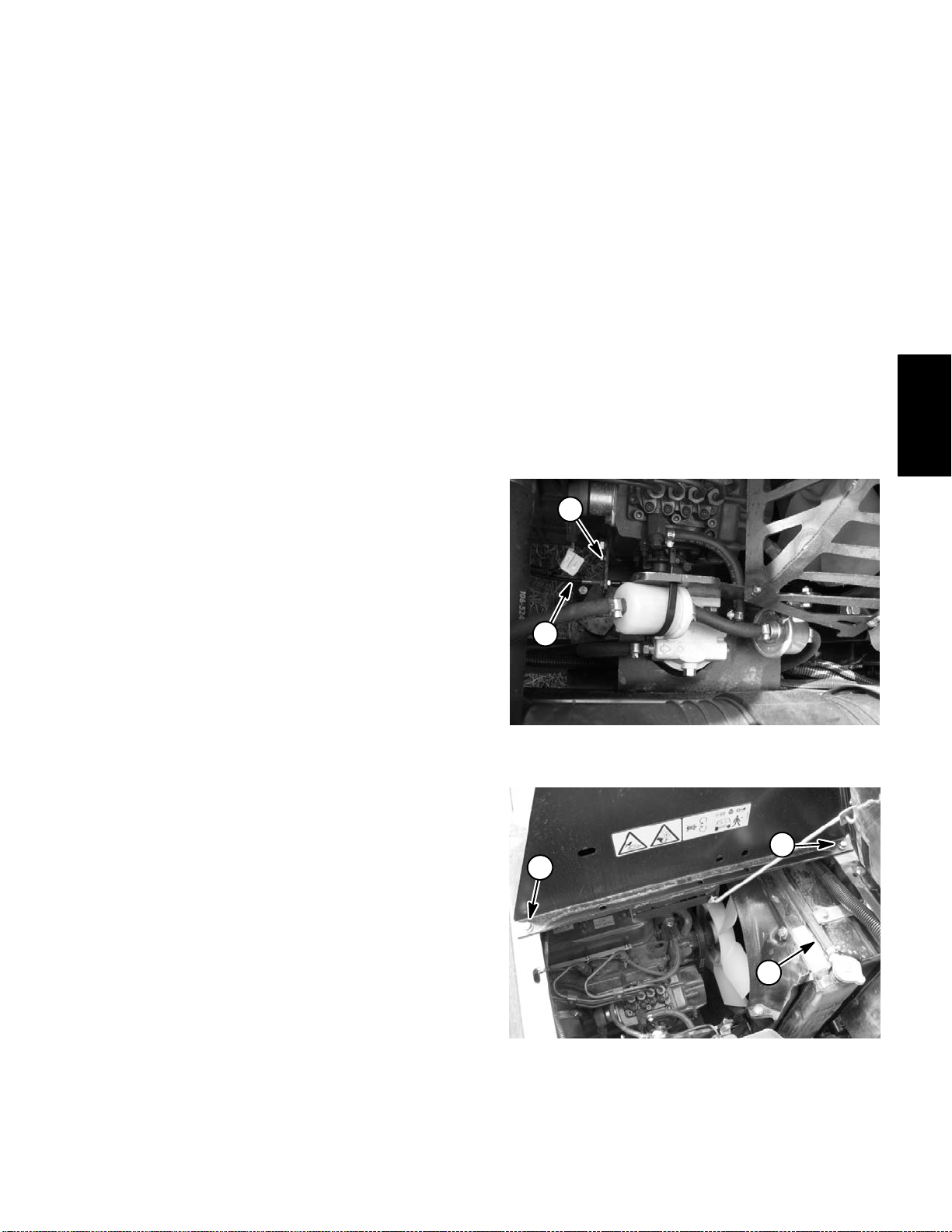
6. Disconnect throttle cable from engine (Fig. 8).
8. Reconnect throttle cable to engine (Fig. 8).
A. Loosen jam nut that secures throttle cable to
throttle plate on engine.
B. Remove e–ring that secures throttle cable to
speed control lever on engine.
C. Position throttle cable away from the engine.
7. Remove fasteners that secure spray control console
to seat box assembly (Fig. 9). Carefully pivot seats and
control console forward to allow radiator access. Take
care not to damage the wire harness or throttle cable.
8. Remove four (4) cap screws (item 19), lock washers
and flat washers that secure fan shroud to radiator.
9. Remove two (2) cap screws (item 22), flat washers
and flange nuts that attach fan shrouds.
10.Carefully lift upper fan shroud from machine.
11. Remove two (2) flange nuts (item 26) that secure the
isomounts on the bottom of the radiator to the machine
frame.
12.Carefully lift radiator up from machine.
A. Position throttle cable end to speed control lever
on engine and secure with e–ring.
B. Secure throttle cable to throttle plate on engine
with jam nut.
9. Secure radiator shroud to radiator with six (6) cap
screws (items 5 and 6), lock washers and flat washers.
10.Place overflow hose to radiator flange and secure
with hose clamp (Fig. 9).
11. Make sure radiator drain is closed. Fill radiator with
coolant (see Operator’s Manual).
12.Check position of wires, hydraulic hoses and control
cables for proper clearance with rotating, high temperature and moving components.
13.Start engine and check for proper operation. Check
all hose connections for leaks.
2
Engine
Kubota Diesel
Installation (Figs. 7)
1. Replace any foam seal pieces that are damaged or
deteriorated.
2. Make sure that lower fan shroud is positioned below
fan.
3. Carefully lower radiator to the machine frame. Secure isomounts on the bottom of the radiator to the machine frame with two (2) flange nuts.
4. Position upper fan shroud to radiator. Attach fan
shrouds with cap screws (item 22), flat washers and
flange nuts.
5. Secure radiator shrouds to radiator with four (4) cap
screws (item 19), lock washers and flat washers. Make
sure that clearance exists between radiator shrouds
and fan at all points before tightening fasteners.
6. Connect lower and upper hoses to the radiator. Secure hoses with hose clamps.
7. Carefully pivot seats and spray control console back
in position taking care not to damage wiring harness or
throttle cable. Install fasteners to secure control console
to seat box assembly.
1
Figure 8
1. Throttle cable 2. Throttle plate
2
2
1
Figure 9
1. Overflow hose 2. Spray console fastener
Multi Pro 5700–D Page 3 – 11 Kubota Diesel Engine
Page 30
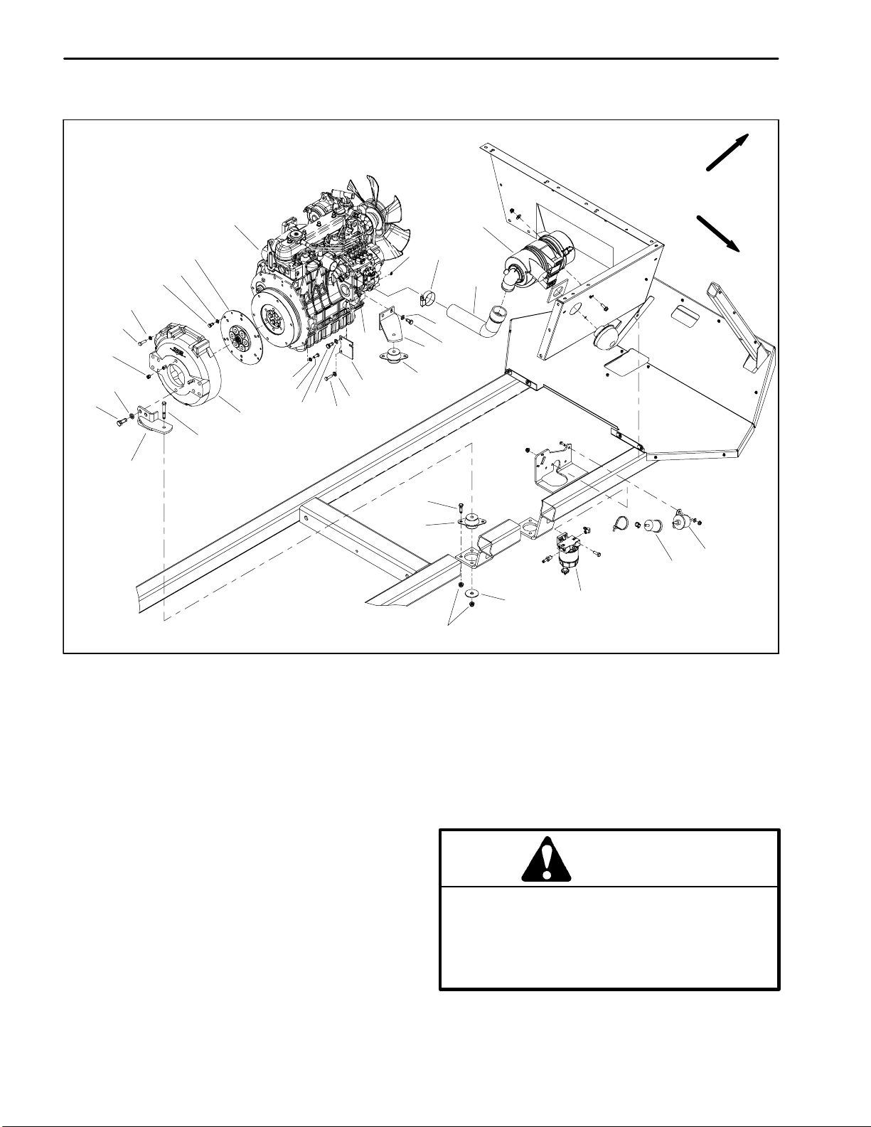
Engine
FRONT
RIGHT
1
5
27
25
19
26
18
28
24
18
23
29
30
18
22
21
20
19
18
16
17
11
2
12
11
15
10
3
13
14
4
6
7
9
8
1. Engine assembly
2. E--ring
3. Hose clamp
4. Air cleaner hose
5. Air cleaner assembly
6. Fuel pump
7. Fuel filter (if equipped)
8. Water/fuel filter
9. Snubbing washer
10. Flange nut
11. Engine mount (4 used)
12. Cap screw
13. Lock washer
14. Cap screw
15. Front engine bracket (RH shown)
16. Lock nut
17. Throttle plate
18. Lock washer
19. Cap screw
20. Lock washer
Removal (Fig. 11)
1. Park machine on a level surface, stop engine and remove key from the ignition switch. Raise machine to allow engine to be lowered from frame.
2. Disconnect negative (--) and then positive (+) battery
cables at the battery.
3. Loosen hose clamps that secure air cleaner hose to
engine air intake and air cleaner assembly. Remove air
cleaner hose.
Kubota Diesel Engine
Page 3 -- 12
Figure 11
21. Cap screw
22. Cap screw
23. Coupling
24. Cap screw
25. Set screw
26. Lock washer
27. Cap screw
28. Rear engine bracket (2 used)
29. Cap screw (4 used)
30. Flywheel housing
CAUTION
Do not open radiator cap or drain coolant if the
radiator or engine is hot. Pressurized, hot coolant can escape and cause burns. Ethylene--glycol antifreeze is poisonous. Dispose of coolant
properly, or storeit in a properly labeled container away from children and pets.
4. Drain coolant from the radiator into a suitable con-
tainer (see Operator’s Manual).
Rev. D
Multi Pro 5700--D
Page 31

CAUTION
1
4
Exhaust system components may be hot. To
avoid possible burns, allow the exhaust system
to cool before working on or near the muffler.
5. Remove exhaust system from engine (see Exhaust
System Removal in this section).
6. Remove upper and lower radiator hoses from engine.
7. Disconnect engine electrical connections. Position
wires away from engine.
NOTE: Label all electrical leads for reassembly purposes.
A. Remove positive battery cable, cable to accessory solenoid and fusible link connector from electric
starter motor solenoid stud (Fig. 11). Remove cable
tie that secures fusible link connector to starter.
B. Disconnect wire harness white wire and violet/
white wire connectors from starter motor.
C. Remove cap screw and lock washer that secure
negative battery cable and wire harness ground wire
to engine (Fig. 11).
D. Remove orange wire from glow plug terminal.
3
2
Figure 11
1. Starter motor stud 3. Harness ground wire
2. Negative battery cable 4. Motor mount
1
Figure 12
1. Temperature sender
Engine
Kubota Diesel
E. Disconnect blue wire from temperature sender
(Fig. 12).
F. Remove cable from alternator stud. Disconnect
wire harness connector from alternator (Fig. 13).
G. Disconnect brown/white wire from oil pressure
switch (Fig. 13).
H. Disconnect wire harness connector from fuel
stop solenoid (Fig. 14).
8. Clamp fuel supply hose after the water/fuel filter to
prevent leakage (Fig. 14). Disconnect fuel hose from the
fuel injector pump on engine. Position disconnected fuel
hose away from engine.
IMPORTANT: Support hydraulic pump assembly to
prevent it from falling and being damaged.
9. Remove hydraulic pump assembly from engine (see
Pump Assembly in Service and Repairs section of
Chapter 4 – Hydraulic System).
2
3
4
Figure 13
1. Alternator 3. Harness connector
2. Alternator stud 4. Oil pressure switch
1
Multi Pro 5700–D Page 3 – 13 Kubota Diesel Engine
Page 32

10.Remove throttle cable from engine (Fig. 14).
A. Loosen jam nut that secures throttle cable to
throttle plate on engine.
B. Remove e–ring that secures throttle cable to
speed control lever on engine.
1
5
2
C. Position throttle cable away from the engine.
11. Note location of any cable ties used to secure the wiring harness, fuel lines or hydraulic hoses to the engine
assembly. Remove cable ties attached to engine assembly.
IMPORTANT: Support engine assembly to prevent
it from falling and being damaged during removal.
12.Remove flange nuts, snubbing washers and cap
screws securing the engine brackets to the machine
frame (Fig. 11).
IMPORTANT: Make sure not to damage the engine,
fuel hoses, hydraulic lines, electrical harness or
other parts while removing the engine assembly.
13.Using a hoist or lift, carefully lower engine from the
machine.
14.If necessary, remove engine brackets from the engine and engine mounts from frame.
Installation (Fig. 10)
1. Locate machine on a level surface with key removed
from the ignition switch. Raise machine to allow engine
to be raised into frame.
2. Make sure that all parts removed from the engine
during maintenance or rebuilding are reinstalled to the
engine.
3. If engine brackets were removed from engine, secure brackets to engine with cap screws and lock washers.
4. If engine mounts were removed from frame, secure
mounts to frame with cap screws and flange nuts.
4
3
Figure 14
1. Fuel stop solenoid 4. Throttle cable
2. Fuel supply hose 5. Throttle plate
3. Water/fuel filter
6. Connect machine wire harness to engine electrical
components (see step 7 in removal procedure).
7. Connect fuel supply hose to the fuel injector pump on
engine (Fig. 14). Remove clamp from fuel hose.
8. Reconnect throttle cable to engine (Fig. 14).
A. Position throttle cable end to speed control lever
on engine and secure with e–ring.
B. Secure throttle cable to throttle plate on engine
with jam nut.
9. Install upper and lower radiator hoses to engine. Se-
cure hoses with hose clamps.
IMPORTANT: During hydraulic pump installation,
support pump to prevent it from falling and being
damaged.
10.Install hydraulic pump assembly to engine (see
Pump Assembly in Service and Repairs section of
Chapter 4 – Hydraulic System).
IMPORTANT: Any leaks in the air intake system will
cause serious engine damage. Make sure that all air
cleaner components are in good condition and are
properly secured during reassembly.
IMPORTANT: Support engine assembly to prevent
it from falling and being damaged during installation.
IMPORTANT: Make sure not to damage the engine,
fuel hoses, hydraulic lines, electrical harness or
other parts while installing the engine assembly.
5. Using a hoist or lift, carefully raise engine assembly
from under machine and position to frame. Insert cap
screws through engine brackets and motor mounts from
above (Fig. 11). Install flange nuts on cap screws and
tighten nuts.
Kubota Diesel Engine
Page 3 – 14
11. Install air cleaner hose to engine and air cleaner as-
sembly. Make sure that hose clamps are properly tight-
ened.
12.Install exhaust system (see Exhaust System Instal-
lation in this section).
13.Install cable ties to secure the wiring harness, fuel
lines and hydraulic hoses to the engine assembly using
notes taken during engine removal.
14.Properly fill the radiator with coolant (see Operator’s
Manual).
Multi Pro 5700–D
Page 33

15.Check engine oil level and adjust if necessary (see
Operator’s Manual).
16.Connect positive (+) and then negative (–) battery
cables to the battery.
17.Check position of wires, fuel lines, hydraulic hoses
and cables for proper clearance with rotating, high temperature and moving components.
18.Start engine and check for proper operation. Check
all hose connections for leaks. Check engine speed.
Engine
Kubota Diesel
Multi Pro 5700–D Page 3 – 15 Kubota Diesel Engine
Page 34

This page is intentionally blank.
Kubota Diesel Engine
Page 3 – 16
Multi Pro 5700–D
Page 35

Table of Contents
Chapter 4
Hydraulic System
SPECIFICATIONS 3.............................
GENERAL INFORMATION 4.....................
Hydraulic Hoses 4............................
Hydraulic Fitting Installation 4...................
Towing S p r a y e r 6.............................
Check Hydraulic Fluid 6.......................
HYDRAULIC SCHEMATIC 8.....................
HYDRAULIC FLOW CIRCUITS 9.................
Traction Circuit 9..............................
Steering Circuit 10............................
Spray Pump Drive Circuit 11....................
SPECIAL TOOLS 12............................
Hydraulic Pressure Test Kit 12..................
Hydraulic Tester (Pressure and Flow) 12.........
Hydraulic Test Fitting Kit 13.....................
TROUBLESHOOTING 14........................
TESTING 16...................................
Traction Circuit Charge Pressure Test 17.........
Traction Circuit Relief Pressure Test 18..........
Gear Pump Flow Test 19.......................
Steering C ircuit Relief Pressure Test 20..........
Steering Control Valve and Steering
Cylinder Test 21.............................
Spray Pump Drive Circuit Relief Pressure Test 22.
Wheel Motor Efficiency: Case Drain Test 23......
Pulse Width Modulated (PWM) Valve Flow Test 24
ADJUSTMENTS 25.............................
Adjust Traction Pedal for Neutral (Machines with
Serial Numbers Below 310000000) 25.........
Adjust Traction Pedal for Neutral (Machines with
Serial Numbers Above 310000000) 25.........
Adjust Relief Valve 26.........................
SERVICE AND REPAIRS 27.....................
General Precautions for Removing and Installing
Hydraulic System Components 27.............
Check Hydraulic Lines and Hoses 27............
Flush Hydraulic System 28.....................
Charge Hydraulic System 29...................
Gear Pump 30................................
Gear Pump Service 32.........................
Piston (Traction) Pump 34......................
Piston (Traction) Pump Service 36..............
Manual Servo Control Assembly 37.............
Wheel Motors 38..............................
Wheel Motor Service 40.......................
Spray Pump Drive Motor 42....................
Spray Pump Drive Motor Service 44.............
Relief Valve 45...............................
Pulse Width Modulated (PWM) Valve 46.........
Steering Control Valve 48......................
Steering Control Valve Service 50...............
Steering Cylinder 52...........................
Steering Cylinder Service 54...................
Oil C ooler 56.................................
Hydraulic Reservoir 58........................
EATON MODEL 26000 SINGLE GEAR PUMP REPAIR
INFORMATION
EATON MODEL 72400 SERVO CONTROLLED PIS-
TON PUMP REPAIR INFORMATION
EATON MODEL 74318 and 74348 PISTON MOTORS:
FIXED DISPLACEMENT, VALVE PLATE DESIGN
REPAIR INFORMATION
PARKER TORQLINK
TM
SERVICE PROCEDURE
System
Hydraulic
Multi Pro 5700--D Hydraulic SystemPage 4 -- 1
Rev. D
Page 36

This page is intentionally blank.
Multi Pro 5700--DHydraulic System Page 4 -- 2
Page 37

Specifications
Item Description
Piston (Traction) Pump Variable displacement piston pump
System Relief Pressure: Forward 4000 PSI (276 bar)
System Relief Pressure: Reverse 4000 PSI (276 bar)
Charge Pressure 250 to 300 PSI (17 to 21 bar)
Gear Pump Single section, positive displacement gear pump
Steering Circuit Relief Pressure 1000 PSI (69 bar)
Spray Pump Circuit Relief Pressure 1500 PSI (103 bar)
Rear Wheel Motors Fixed displacement piston motor
Spray Pump Motor Orbital rotor motor
Hydraulic Filter 10 Micron spin--on cartridge type
Hydraulic Reservoir 12 gal. (45 l)
Hydraulic Oil See Operator’s Manual
System
Hydraulic
Multi Pro 5700--D Hydraulic SystemPage 4 -- 3
Page 38

General Information
Hydraulic Hoses
Hydraulic hoses are s ubject to extreme conditions such
as pressure differentials during operation and exposure
to weather, sun, chemicals, very warm storage conditions, or mishandling during operation and maintenance. These conditions can cause damage or
premature deterioration. Some hoses are more susceptible to these conditions than others. Inspect the hoses
frequently for signs of deterioration or damage.
WARNING
Before disconnecting or performing any work
on hydraulic system, relieve all pressure in
system. Stop engine and rotate the steering
wheel.
When replacing a hydraulic hose, be sure that the hose
is straight (not twisted) before tightening the fittings.
This can be done by observing the imprint on the hose.
Use two wrenches; hold the hose straight with one
wrench and tighten the hose swivel nut onto the fitting
with the other wrench.
Hydraulic Fitting Installation
O--Ring Face Seal
1. Make sure both threads and sealing surfaces are
free of burrs, nicks, scratches, or any foreign material.
2. Make sure the O-- ring is installed and properly
seated in the groove. It is recommended that the O--ring
be replaced any time the connection is opened.
3. Lubricate the O--ring with a light coating of o il.
4. Put the tube and nut squarely into position on the
face seal end of the fitting and tighten the nut until finger
tight.
Keep body and hands away from pin hole leaks
or nozzles that eject hydraulic fluid under high
pressure. Use paper or cardboard, not hands,
to search for leaks. Hydraulic fluid escaping
under pressure can have sufficient force to
penetrate the skin and cause serious injury. If
fluid is injected into the skin, it must be surgically removed within a few hours by a doctor
familiar with this type of injury. Gangrene may
result from such an injury.
Nut
Sleeve
Seal
Body
Figure 1
5. Mark the nut and fitting body. Hold the body with a
wrench. Use another wrench to tighten the nut to the correct Flats From Finger Tight (F.F.F.T.). The markings on
the nut and fitting body will verify that the connection has
been tightened.
Siz e F.F.F. T.
4 (1/4 in. nominal hose or tubing) 0.75 +
6(3/8in.) 0.75+
8(1/2in.) 0.75+
10 (5/8 in.) 1.00 +
12 (3/4 in.) 0.75 +
16 (1 in.) 0.75 +
0.25
0.25
0.25
0.25
0.25
0.25
Final
Position
Mark Nut
and Body
Extend Line
Initial
Position
Finger Tight After Proper Tightening
Figure 2
Multi Pro 5700--DHydraulic System Page 4 -- 4
Page 39

SAE Straight Thread O--Ring Port -- Non-- adjustable
1. Make sure both threads and sealing surfaces are
free of burrs, nicks, scratches, or any foreign material.
2. Always replace the O--ring seal when this type of fitting shows signs of leakage.
3. Lubricate the O--ring with a light coating of o il.
4. Install the fitting into the port and tighten it down full
length until finger tight.
5. Tighten the fitting to the correct Flats From Finger
Tight (F.F.F.T.).
Siz e F.F.F. T.
4 (1/4 in. nominal hose or tubing) 1.00 +
6(3/8in.) 1.50+
8(1/2in.) 1.50+
10 (5/8 in.) 1.50 +
12 (3/4 in.) 1.50 +
16 (1 in.) 1.50 +
0.25
0.25
0.25
0.25
0.25
0.25
NOTE: Installation torque values for non--adjustable fittings are listed in Figure 4. These torque values should
only be used when a fitting can be accessed with a
socket. Use of an offset wrench (e.g. crowfoot wrench)
will affect torque wrench accuracy and should not be
used.
SAE Straight Thread O--Ring Port -- Adjustable
1. Make sure both threads and sealing surfaces are
free of burrs, nicks, scratches, or any foreign material.
O--Ring
Figure 3
Fitting Size Installation Torque
4 9--10ft--lb(12--13N--m)
6 2 0 -- 2 1 f t -- l b ( 2 7 -- 2 8 N -- m )
8 3 5 -- 3 7 f t -- l b ( 4 7 -- 5 0 N -- m )
10 6 0 -- 6 6 f t -- l b ( 8 1 -- 8 9 N -- m )
12 8 1 -- 8 7 f t -- l b ( 1 1 0 -- 1 1 7 N -- m )
16 121--131 ft--lb (164-- 177 N--m)
Figure 4
System
Hydraulic
2. Always replace the O--ring seal when this type of fitting shows signs of leakage.
3. Lubricate the O--ring with a light coating of o il.
4. Turn back the jam nut as far as possible. Make sure
the back up washer is not loose and is pushed up as far
as possible (Step 1).
5. Install the fitting into the port and tighten finger tight
until the washer contacts the face of the port (Step 2).
6. To put the fitting in the desired position, unscrew it by
the required amount, but no more than one full turn
(Step 3).
7. Hold the fitting in the desired position with a wrench
and turn the jam nut with another wrench to the correct
Flats From Finger Tight (F.F.F.T.) (Step 4).
Siz e F.F.F. T.
4 (1/4 in. nominal hose or tubing) 1.00 +
6(3/8in.) 1.50+
8(1/2in.) 1.50+
10 (5/8 in.) 1.50 +
12 (3/4 in.) 1.50 +
16 (1 in.) 1.50 +
0.25
0.25
0.25
0.25
0.25
0.25
Lock Nut
Back--up Washer
O--Ring
Figure 5
Step 3Step 1
Step 2 Step 4
Figure 6
Multi Pro 5700--D Hydraulic SystemPage 4 -- 5
Page 40

Towing Sprayer
IMPORTANT: If towing limits are exceeded, severe
damage to the piston (traction) pump may occur.
If it becomes necessary to tow (or push) the machine,
tow (or push) at a speed below 3 mph (4.8 kph).The
piston (traction) pump is equipped with a by--pass valve
that needs to be turned 90
o
for towing (or pushing). See
Operator’s Manual for Towing Procedures.
Check Hydraulic Fluid
The Multi Pro 5700--D hydraulic system is designed to
operate on anti--wear hydraulic fluid. The reservoir
holds approximately 12 gallons (45 liters) of hydraulic
fluid. Check level of hydraulic fluid daily. See Operator’s Manual for fluid level checking procedure and hydraulic oil recommendations.
1
Figure 7
1. By--pass valve location
1
Figure 8
1. Hydraulic reservoir cap
Multi Pro 5700--DHydraulic System Page 4 -- 6
Page 41

This page is intentionally blank.
System
Hydraulic
Multi Pro 5700--D Hydraulic SystemPage 4 -- 7
Page 42

Hydraulic Schematic
VALV E
FLRT
STEERING
T = TANK
R = WORKING PRESSURE
L = WORKING PRESSURE
P = PRESSURE
STEERING
CYLINDER
FLOW DURING
RIGHT TURN
(3 GPM) (0--1000PSI)
PRIORITY FLOW
SECONDARY
FLOW
RELIEF
(3 GPM) (0--75 PSI)
VALV E
OIL COOLER
RADIATOR
KUBOTA
DIESEL
ENGINE
PISTON
PUMP
UPPER
LOWER
PUMP
GEAR
MAIN RETURN
(12.5 GPM) (0 -- 20 PSI)
(0--20 PSI)
SPRA Y PUMP
TO REMOTE
PUMP
CHARGE
PRESSURE
(9.5 GPM) (0 --75 PSI)
NOMINAL SPRAYER
(9.5 GPM SECONDARY FLOW) (0-- 1500 PSI)
IN
(0--9.5 GPM)
EX = BYPASS
PULSE WIDTH
MODULATED
VALV E
PRESSURE)
FLOW DURING
(CHARGE PUMP
WHEEL
MOTOR
EX
MOTOR
HYDRAULIC
CF
FLOW
CF = CONTROLLED
IN = PRESSURE
FORWARD MOTION
FILTER
(5.8 GPM)
(275 PSI)
CHARGE PORT
(0--17 GPM MAX)
FLOW DURING FORWARD MOTION
MAIN PRESSURE
CASE DRAIN
(0--4000 PSI)
(13 GPM VAC)
WHEEL
MOTOR
(5.8 GPM VAC)
HYDRAULIC
NOTE: FLOWS SHOWN ARE AT
FULL ENGINE SPEED (3100 RPM),
RESERVOIR
FORWARD MOTION AND TURNING
TO THE RIGHT
Multi Pro 5700--DHydraulic System Page 4 -- 8
Page 43

Hydraulic Flow Circuits
Traction Circuit
The traction circuit piston pump is a variable displacement pump that is directly coupled to the engine flywheel. Pushing the top of the traction pedal rotates the
pump swash plate to create a flow of oil for forward machine movement. Pushing the bottom of the traction
pedal rotates the pump swash plate to cause oil flow for
reverse machine movement. This oil is directed to the
rear wheel motors. Operating pressure on the high pressure side of the closed traction circuit loop is determined
by the amount of load developed at the fixed displacement wheel motors. As the load increases, circuit pressure can increase to relief valve settings: 4000 PSI in
either forward or reverse. If pressure exceeds the relief
setting, oil flows through the relief valve to the low pressure side of the closed loop circuit.
Traction circuit pressure (forward or reverse) can be
measured by installing a tee fitting and gauge into the
traction system hydraulic lines.
The piston (traction) pump and wheel motors use a
small amount of hydraulic oil for internal lubrication. Oil
is designed to leak across pump and motor parts into the
case drain. This leakage results in the loss of hydraulic
oil from the closed loop traction circuit that must be replaced.
The piston (traction) pump incorporates a charge pump
that provides make–up oil for the traction circuit. This
gerotor gear pump is driven by the piston pump drive
shaft. It provides a constant supply of charge oil to the
traction circuit to make up for oil that is lost due to internal leakage in the piston pump and wheel motors.
Charge pump flow is directed through the oil filter and to
the low pressure side of the closed loop traction circuit.
Pressure in the charge circuit is limited by a relief valve
located in the charge plate adapter on the rear of the piston pump. Charge pump pressure can be measured at
the auxiliary test port on the side of the piston pump.
System
Hydraulic
Multi Pro 5700–D Page 4 – 9 Hydraulic System
Page 44
Steering Circuit
A single section gear pump is coupled to the piston (traction) pump. The gear pump supplies hydraulic flow to
the steering control valve and the spray pump drive hydraulic motor. Pump hydraulic flow is delivered to the
two circuits through a flow divider with the steering circuit having priority. The gear pump takes its suction from
the hydraulic reservoir. Steering circuit pressure is limited by a relief valve located in the gear pump.
The steering control valve includes a check valve that allows steering operation when the engine is not running.
Steering wheel rotation with the engine off causes oil
flow from the steering control gerotor. The check valve
opens in this situation to allow oil flow from the steering
control to the steering cylinder in a closed loop.
Hydraulic flow and pressure to the steering control valve
can be monitored at the outlet of the gear pump.
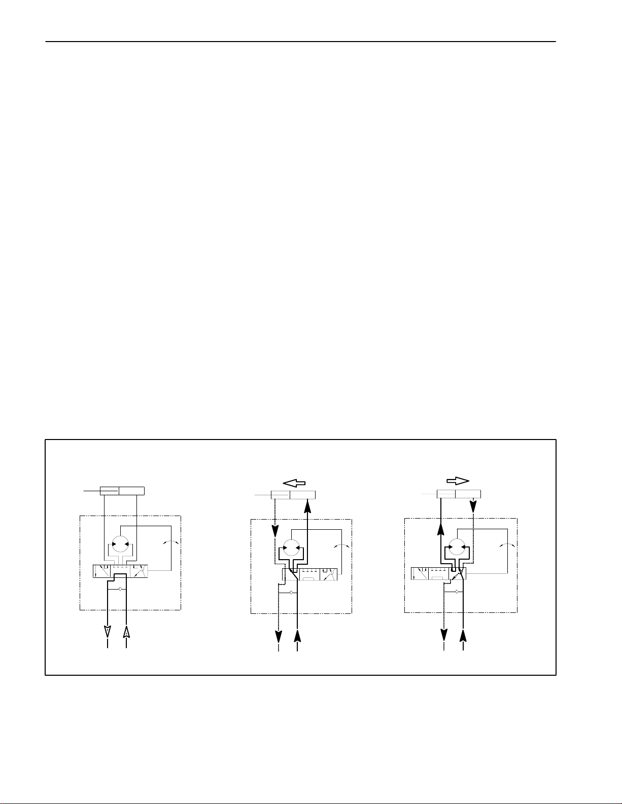
With the steering wheel in the neutral position and the
engine running, gear pump flow enters the steering control valve (port P) and goes through the steering control
spool valve, by–passing the rotary meter (V1) and steering cylinder. Flow leaves the control valve (port T), to the
oil cooler, and returns to the hydraulic oil reservoir.
Left Turn
that flow goes through the top of the spool. Flow entering
the steering control valve from the gear pump goes
through the spool and is routed through the rotary meter
(V1) and out the L port. Pressure extends the steering
cylinder piston for a left turn. The rotary meter ensures
that the oil flow to the cylinder is proportional to the
amount of the turning on the steering wheel. Fluid leaving the cylinder flows back through the spool valve, then
to the oil cooler and returns to the reservoir.
The steering control valve returns to the neutral position
when turning is completed.
Right Turn
When a right turn is made with the engine running, the
turning of the steering wheel positions the spool valve so
that flow goes through the bottom of the spool. Flow entering the steering control valve from the gear pump
goes through the spool and is routed through rotary meter (V1) but goes out port R. Pressure contracts the
steering cylinder piston for a right turn. The rotary meter
ensures that the oil flow to the cylinder is proportional to
the amount of the turning on the steering wheel. Fluid
leaving the cylinder flows back through the spool valve,
then to the oil cooler and returns to the reservoir.
When a left turn is made with the engine running, the
turning of the steering wheel positions the spool valve so
STEERING CYLINDER
NO PISTON MOVEMENT
R L
T P
NEUTRAL POSITION
STEERING
CONTROL
STEERING CYLINDER
PISTON MOVEMENT
R
T
LEFT TURN
Figure 9
The steering control valve returns to the neutral position
when turning is completed.
STEERING CYLINDER
PISTON MOVEMENT
L
P
STEERING
CONTROL
R
T
RIGHT TURN
L
P
STEERING
CONTROL
Hydraulic System Page 4 – 10 Multi Pro 5700–D
Page 45

Spray Pump Drive Circuit
A single section gear pump is coupled directly to the piston (traction) pump. The gear pump supplies hydraulic
flow to the steering control valve and the spray pump
drive hydraulic motor. Gear pump hydraulic flow is delivered to the two circuits through a flow divider with the
steering circuit having priority. The gear pump takes its
suction from the hydraulic reservoir. Spray pump drive
circuit pressure is limited by an adjustable relief valve located on the outside of the piston (traction) pump.
Spray pump drive circuit hydraulic flow and pressure
can be monitored at the outlet of the gear pump.
Hydraulic flow control for the spray pump drive hydraulic
motor is completed by the Pulse Width Modulated
(PWM) Valve. The PWM Valve consists of an electric solenoid valve that allows the operator to adjust hydraulic
flow to the spray pump motor. The spray pump on/off
and application rate (increase/decrease) switches are
used to adjust electrical current to the PWM Valve solenoid.
With the engine running and the spray pump switch in
the OFF position, the solenoid valve in the PWM Valve
is not energized. All gear pump flow to the PWM Valve
is directed out the EX port of the PWM Valve, to the oil
cooler, and returns to the hydraulic oil reservoir. The
spray pump hydraulic motor receives no hydraulic flow
so the spray system pump is not rotated and no spray
system flow is available.
With the engine running and the spray pump switch in
the ON position, the solenoid valve in the PWM Valve is
energized. Based on available current (mA) from the
spray pump application rate (increase/decrease)
switch, the solenoid spool valve in the PWM Valve directs some gear pump flow out the CF port to the spray
pump hydraulic motor. This hydraulic flow causes the
motor to rotate the spray system pump for spray system
operation. Gear pump hydraulic flow in excess of PWM
solenoid spool valve setting is directed out the EX port
of the PWM Valve, to the oil cooler, and returns to the hydraulic oil reservoir.
The spray pump application rate (increase/decrease)
switch allows the operator to adjust electrical current to
the PWM Valve solenoid. Higher current (rate increase)
to the PWM Valve solenoid increases hydraulic flow to
the spray pump motor and results in a higher spray
pump speed with more spray system output/pressure.
Lower current (rate decrease) to the PWM Valve solenoid decreases hydraulic flow to the spray pump motor
and results in a lower spray pump speed with less spray
system output/pressure.
NOTE: Correct operation of the PWM Valve depends
on precision manufacturer’s assembly and adjustment.
No disassembly or adjustment of the PWM Valve is recommended.
System
Hydraulic
Multi Pro 5700–D Page 4 – 11 Hydraulic System
Page 46

Special Tools
Order these special tools from your Toro Distributor.
Hydraulic Pressure Test Kit
Toro Part Number: TOR47009
Use to take various pressure readings for diagnostic
tests. Quick disconnect fittings provided attach directly
to mating fittings on machine test ports without tools. A
high pressure hose is provided for remote readings.
Contains one each: 1000 PSI (70 Bar), 5000 PSI (350
Bar) and 10000 PSI (700 Bar) gauges. Use gauges as
recommended in Testing section of this chapter.
Hydraulic Tester (Pressure and Flow)
Figure 10
Toro Part Number: TOR214678
Use to test hydraulic circuits and components for flow
and pressure capacities as recommended in the Testing
section of this chapter.This tester includes the following:
1. INLET HOSE: Hose connected from the system circuit to the inlet side of the hydraulic tester.
2. LOAD VALVE: A simulated working load is created
in the circuit by turning the valve to restrict flow.
3. PRESSURE GAUGE: Glycerine filled 0 to 5000 PSI
gauge to provide operating circuit pressure.
4. FLOW METER: This meter measures actual oil flow
in the operating circuit with a gauge rated from 1 to 15
GPM(5to55LPM).
5. OUTLET HOSE: A hose from the outlet side of the
hydraulic tester connects to the hydraulic system circuit.
6. FITTINGS: An assortment of hydraulic fittings are included with this kit.
Figure 11
Rev. D
Multi Pro 5700--DHydraulic System Page 4 -- 12
Page 47
O --Ring Kit
Toro Part Number: 16--3799
The kit includes O--ringsin a variety of sizes for face seal
and port seal hydraulic connections. It is recommended
that O--rings be replaced whenever a hydraulic connection is loosened.
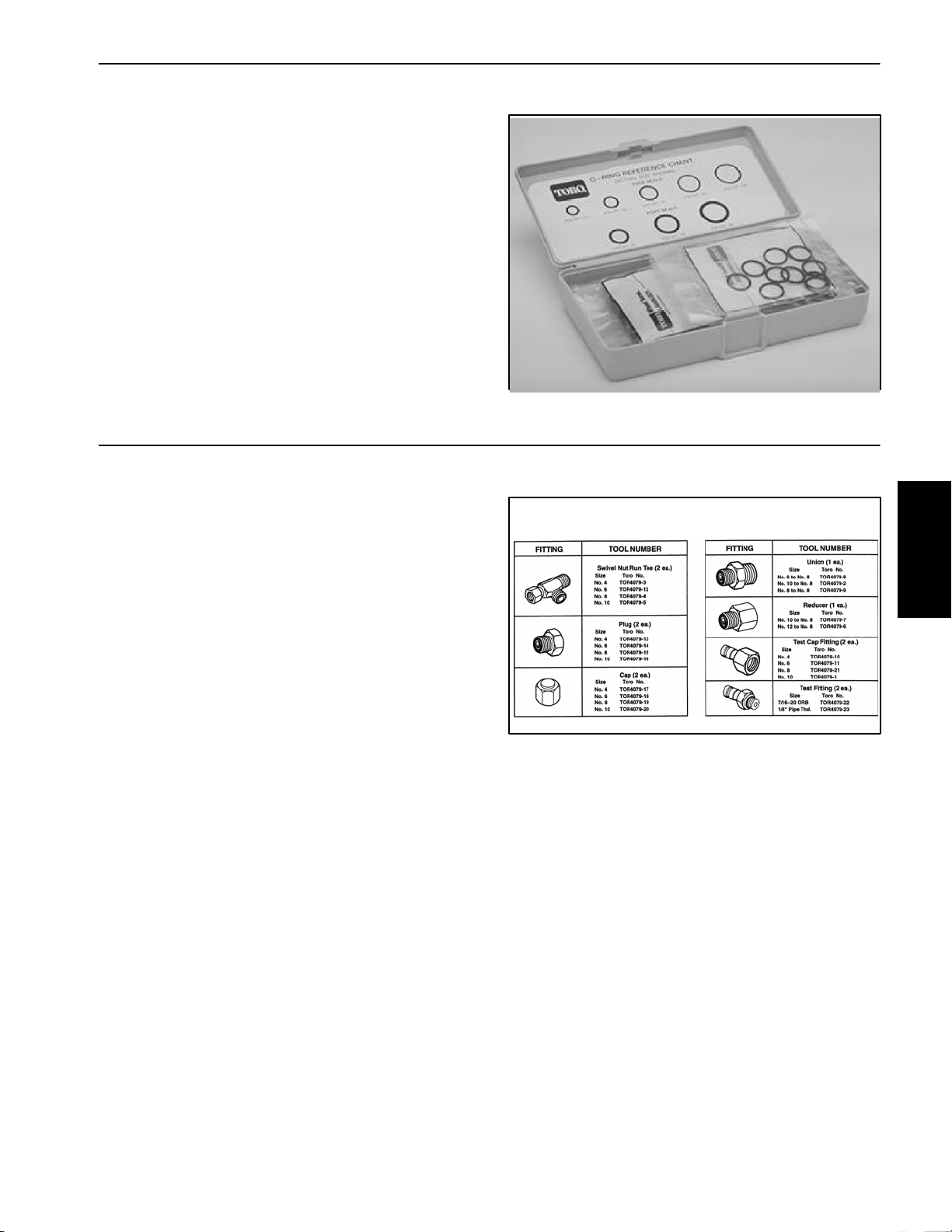
Hydraulic Test Fitting Kit
Toro Part Number: TOR4079
This kit includes a variety of O--ring Face Seal fittings to
enable connection of test gauges to the hydraulic system.
The kit includes: tee’s, unions, reducers, plugs, caps
and test fittings.
Figure 12
TORO TEST FITTING KIT (NO. TOR4079)
System
Hydraulic
System
Hydraulic
Multi Pro 5700--D Hydraulic SystemPage 4 -- 13
Figure 13
Rev. C
Page 48

Troubleshooting
The cause of an improperly functioning hydraulic system is best diagnosed with the use of proper testing
equipment and a thorough understanding of the complete hydraulic system.
A hydraulic system with an excessive increase in heat
or noise has a potential for failure. Should either of these
conditions be noticed, immediately stop the machine,
turn off the engine, locate the cause of the trouble, and
correct it before allowing the machine to be used again.
Problem Possible Cause
Hydraulic oil leaks. Hydraulic fitting(s) or hose(s) are loose or damaged.
O--ring(s) or seal(s) are missing or damaged.
Foaming hydraulic fluid. Oil level in reservoir is incorrect.
Hydraulic system has wrong kind of oil.
Piston and/or gear pump suction line has an air leak.
Water in hydraulic system.
Hydraulic system operates hot. Oil level in reservoir is incorrect.
Continued use of an improperly functioning hydraulic
system could lead to extensive internal component
damage.
The chart that follows contains information to assist in
troubleshooting. There may possibly be more than one
cause for a machine malfunction.
Refer to the Testing section of this Chapter for precautions and specific test procedures.
Hydraulic hose is kinked.
Oil is contaminated or incorrect viscosity.
Brakes are engaged or sticking.
Piston pump by--pass valve is open or damaged.
Hydraulic oil cooling system is not operating properly.
Charge pressure is low.
Traction circuit pressure is incorrect.
Wheel motor(s) or spray pump motor is/are worn or damaged.
Gear pump or piston (traction) pump is worn or damaged.
Machine operates in one direction
only.
Traction pedal is sluggish. Traction control linkage is stuck or binding.
Traction control linkage is faulty.
System charge check valve and/or system relief valve is defective.
Piston pump manual servo control assembly is damaged.
Piston pump or wheel motor(s) are worn or damaged.
Charge pressure is low.
Multi Pro 5700--DHydraulic System Page 4 -- 14
Page 49

Machine travels too far before stopping when the traction pedal is released.
Traction linkage is binding or out of adjustment.
Piston pump manual servo control assembly is damaged.
Traction pedal does not return to neutral.
Traction power is lost or unit will not
Brakes are engaged or sticking.
operate in either direction.
Traction control linkage is damaged or disconnected.
Hydraulic reservoir oil level is low.
Piston pump by--pass valve is open or damaged.
Charge pressure is low.
Traction circuit pressure is low.
Rear wheel motor couplers are damaged.
Steering inoperative or sluggish Engine speed is too low.
Steering cylinder is binding.
Reservoir oil level is low.
Check valve in steering control valve is sticking, worn or damaged.
Steering relief valve is stuck open.
Steering control valve is worn or damaged.
Steering cylinder leaks internally.
System
Hydraulic
Turning steering wheel turns machine in the wrong direction.
Spray pump hydraulic motor does
not rotate.
Priority valve in gear pump is sticking, worn or damaged.
Gear pump is worn or damaged.
Hoses to the steering cylinder are reversed.
Steering cylinder has internal leak.
PWM Valve solenoid valve is sticking or damaged.
PWM Valve solenoid or circuit wiring has electrical problem (see
Chapter 5 -- Electrical System).
Priority valve in gear pump is sticking or damaged.
Spray pump hydraulic motor is worn or damaged.
Multi Pro 5700--D Hydraulic SystemPage 4 -- 15
Page 50

Testing
The most effective method for isolating problems in the
hydraulic system is by using hydraulic test equipment
such as pressure gauges and flow meters in the hydraulic circuits during various operational checks (See the
Special Tools section in this Chapter).
Before Performing Hydraulic Tests
IMPORTANT: All obvious areas such as hydraulic
oil supply, oil filter, binding linkages, loose fasteners, or improper adjustments must be checked before assuming that a hydraulic component is the
source of a hydraulic problem.
CAUTION
All testing should be performed by two (2)
people. One person should be in the seat to operate the machine, and the other person should
read and record test results.
1. Clean machine thoroughly before disconnecting or
disassembling any hydraulic components. Always keep
in mind the need for cleanliness when working on hydraulic equipment. Contamination will cause excessive
wear of hydraulic components.
WARNING
Before performing any work on the hydraulic
system, system pressure must be relieved and
all rotating machine parts must come to a stop.
Turn ignition switch OFF and remove key from
switch. When engine has stopped rotating, operate all hydraulic controls to relieve hydraulic
system pressure.
Precautions for Hydraulic Testing
CAUTION
Failure to use gauges with recommended pressure (PSI) rating as listed in test procedures
could result in damage to the gauge and possible
personal injury from leaking hot oil.
WARNING
Keep body and hands away from pin hole leaks
or nozzles that eject hydraulic fluid under high
pressure. Do not use hands to search for
leaks; use paper or cardboard. Hydraulic fluid
escaping under pressure can have sufficient
force to penetrate the skin and cause serious
injury. If fluid is injected into the skin, it must
be surgically removed within a few hours by a
doctor familiar with this type of injury. Gangrene may result from such an injury.
2. Put metal caps or plugs on any hydraulic lines left
open or exposed during testing or removal of components.
3. The engine must be in good operating condition. Use
a phototac to check engine speed when performing a
hydraulic test. Engine speed will affect the accuracy of
the tester readings.
4. The inlet and the outlet hoses for tester with pressure
and flow capabilities must be properly connected. If
hoses are reversed, damage to the hydraulic tester or
components can occur.
5. When using hydraulic tester with pressure and flow
capabilities, completely open tester load valve before
starting engine to minimize the possibility of damage to
components.
6. Install tester fittings finger tight and far enough to
make sure that they are not cross–threaded before tightening them with a wrench.
7. Position tester hoses to prevent rotating machine
parts from contacting and damaging the hoses or tester.
8. Check oil level in the hydraulic reservoir. After connecting test equipment, make sure reservoir is full.
9. Check control linkages for improper adjustment,
binding, or broken parts.
10.After installing test gauges, run engine at low speed
and check for any hydraulic oil leaks.
11. All hydraulic tests should be made with the hydraulic
oil at normal operating temperature.
12.Before returning machine to use, make sure that hydraulic reservoir has correct fluid level. Also, check for
hydraulic leaks after test equipment has been removed
from hydraulic system.
Hydraulic System Page 4 – 16 Multi Pro 5700–D
Page 51

Traction Circuit Charge Pressure Test
1. Make sure hydraulic oil is at normal operating temperature by operating the machine for approximately 10
minutes. Make sure the hydraulic tank is full.
2. Park machine on a level surface, stop engine, engage parking brake, and remove key from the ignition
switch. After turning engine off, operate all hydraulic
controls to relieve hydraulic system pressure.
CAUTION
Prevent personal injury and/or damage to equipment. Read all WARNINGS, CAUTIONS, and Precautions for Hydraulic Testing at the beginning
of this section.
3. Remove plug from auxiliary test port on left side of
piston (traction) pump (Fig. 13). Connect a 1000 PSI
gauge into auxiliary test port.
4. After installing pressure gauge, start engine and run
at idle speed. Check for hydraulic leakage and correct
before proceeding with test.
5. Operate the engine at high idle engine speed (3050
– 3150 RPM) with no load on the hydraulic system.
1
Figure 13
1. Auxiliary test port plug
System
Hydraulic
GAUGE READING TO BE 250 to 300 PSI.
6. Stop engine and record test results.
7. If there is no pressure, or pressure is low, check for
restriction in pump suction line. Also, inspect charge relief valve located in charge pump adapter on piston
pump. If necessary, check for internal damage or worn
parts in charge pump.
8. Also, with the pressure gauge still connected to the
auxiliary test port on piston pump, take a gauge reading
while operating the machine in forward and reverse.
Start the engine and put throttle at high idle engine
speed. Apply the brakes and push the traction pedal forward, then reverse.
GAUGE READING TO BE 250 to 300 PSI.
9. If charge pressure is good under no load, but drops
below specification when under traction load, the piston
(traction) pump and/or traction wheel motor(s) should
be suspected of wear and inefficiency. When the piston
pump and/or traction motor(s) are worn or damaged, the
charge pump is not able to keep up with internal leakage
in traction circuit components.
10.Disconnect pressure gauge from piston pump and
reinstall plug to auxiliary test port.
Multi Pro 5700–D Page 4 – 17
Hydraulic System
Page 52

Traction Circuit Relief Pressure Test
1. Make sure hydraulic oil is at normal operating temperature by operating the machine for approximately 10
minutes. Make sure the hydraulic tank is full.
2. Park machine on a level surface, stop engine, engage parking brake, and remove key from the ignition
switch. After turning engine off, operate all hydraulic
controls to relieve hydraulic system pressure.
CAUTION
Prevent personal injury and/or damage to equipment. Read all WARNINGS, CAUTIONS, and Precautions for Hydraulic Testing at the beginning
of this section.
3. Clean and disconnect hydraulic pressure hose from
piston pump fitting on right side of pump for function to
be checked (Fig. 14):
Forward pressure hose is upper hose
Reverse pressure hose is lower hose
9. Release traction pedal and stop engine. Record test
results.
10.If traction pressure is too low, inspect traction pump
relief valves (Fig. 15). Clean or replace valves as necessary. These cartridge type valves are factory set, and
are not adjustable. If relief valves are in good condition,
traction pump or wheel motors should be suspected of
wear and inefficiency.
11. Disconnect pressure gauge from machine and reconnect hydraulic hose.
1
2
4. Install T–connector with 10,000 PSI test gauge between the piston pump fitting and the disconnected
hose.
5. After installing pressure gauge, start engine and run
at idle speed. Check for hydraulic leakage and correct
before proceeding with test.
6. Operate the engine at high idle speed (3050 – 3150
RPM).
CAUTION
Move machine to an open area, away from people
and obstructions.
7. Drive machine to an open area and engage the parking brake.
8. Sit on seat, apply brakes fully, and slowly depress the
traction pedal in the appropriate direction (forward or reverse). While pushing traction pedal, look at pressure
reading on gauge:
Figure 14
1. Forward pressure hose 2. Reverse pressure hose
1
2
Figure 15
1. Forward relief valve 2. Reverse relief valve
GAUGE READING TO BE:
Forward: maximum of 4000 PSI
Reverse: maximum of 4000 PSI
Hydraulic System Page 4 – 18 Multi Pro 5700–D
Page 53

Gear Pump Flow Test
Output from the gear pump is divided by a priority flow
divider to allow priority flow to the steering circuit and
secondary flow to the spray pump drive circuit. To test
gear pump flow, testing of both circuits is required. Total
gear pump flow is the combined flow from the two circuits. If a problem is suspected in one of the two circuits,
flow for that circuit should be measured to determine if
the problem is pump related or is involved with other circuit components.
1. Make sure hydraulic oil is at normal operating temperature by operating the machine for approximately 10
minutes. Make sure the hydraulic tank is full.
2. Park machine on a level surface, stop engine, engage parking brake, and remove key from the ignition
switch. After turning engine off, operate all hydraulic
controls to relieve hydraulic system pressure.
CAUTION
Prevent personal injury and/or damage to equipment. Read all WARNINGS, CAUTIONS, and Precautions for Hydraulic Testing at the beginning
of this section.
IMPORTANT: Make sure that the oil flow indicator
arrow on the flow meter is showing that the oil will
flow from the pump, through the tester, and into the
hydraulic hose.
6. While watching tester pressure gauges, slowly close
flow control valve on the tester until 800 PSI is obtained
on gauge. Verify engine speed continues to be within
spec. Record flow meter reading.
GAUGE READING TO BE: For steering circuit, flow
should be approximately 3 GPM at 800 PSI. For
spray motor circuit, flow should be approximately 9.5
GPM at 800 PSI.
7. Open tester flow control valve and stop engine.
NOTE: Relief pressure for steering and/or spray pump
drive circuits can be determined with the tester positioned as described in this test.
8. Remove tester and reinstall disconnected hose.
Complete steps 3 through 6 for other circuit hose.
9. If the total of the two flows is less than 12.5 GPM or
a pressure of 800 PSI could not be obtained, check for
restriction in pump suction line. If suction line is not restricted, remove gear pump and repair or replace as
necessary.
If the total of the two flows is 12.5 GPM but individual circuit flow is incorrect (e.g. steering circuit has 6 GPM and
spray motor circuit has 6.5 GPM), suspect a problem
with one of circuits or with the priority flow divider in the
gear pump.
System
Hydraulic
3. With the engine off, clean hose fitting and disconnect
one of the circuit pressure hoses from the gear pump
(Fig. 16). Install tester with pressure gauges and flow
meter in series between the gear pump and the disconnected hose. Make sure the tester flow control valve
is open.
4. After installing tester, start engine and run at idle
speed. Check for hydraulic leakage and correct before
proceeding with test.
IMPORTANT: The gear pump is a positive displacement type. If pump flow is completely restricted or
stopped, damage to the gear pump, tester, or other
components could occur.
5. Operate the engine at high idle speed (3050 – 3150
RPM). Verify engine speed with a phototac.
Multi Pro 5700–D Page 4 – 19 Hydraulic System
1. Steering circuit pressure hose
2. Spray motor circuit pressure hose
1
Figure 16
2
Page 54

Steering Circuit Relief Pressure Test
1. Make sure hydraulic oil is at normal operating temperature by operating the machine for approximately 10
minutes. Make sure the hydraulic tank is full.
2. Park machine on a level surface, stop engine, engage parking brake, and remove key from the ignition
switch. After turning engine off, operate all hydraulic
controls to relieve hydraulic system pressure.
CAUTION
Prevent personal injury and/or damage to equipment. Read all WARNINGS, CAUTIONS, and Precautions for Hydraulic Testing at the beginning
of this section.
3. Clean hose fitting and disconnect lower pressure
hose from the left side of the gear pump (Fig. 17).
4. Install T–connector with 5,000 PSI pressure gauge
in series with the pump and the disconnected hose.
5. After installing pressure gauge, start engine and run
at idle speed. Check for hydraulic leakage and correct
before proceeding with test.
6. Start engine and adjust engine speed to high idle
(3050 – 3150 RPM).
IMPORTANT: Hold steering wheel at full lock only
long enough to get a system pressure reading.
Holding the steering wheel against the stop for an
extended period will damage the steering motor.
7. Watch pressure gauge carefully while turning the
steering wheel completely in one direction (full steering
lock) and holding momentarily.
1
2
Figure 17
1. Steering circuit pressure hose
2. Spray motor circuit pressure hose
2
1
Figure 18
1. Steering relief valve 2. Gear pump suction hose
8. System pressure should be approximately 1000 PSI
as the relief valve lifts. Return steering wheel to the center position.
9. Slow engine speed and turn off machine. Record test
results.
10.If relief pressure is incorrect, inspect for worn, stuck,
or out of adjustment relief valve. Steering relief valve is
located under the suction hose on the right side of the
gear pump (Fig. 18). For adjustment procedure, see Adjust Relief Valve in the Adjustments section of this Chapter. After adjustment, retest relief valve pressure.
11. Disconnect T–connector and pressure gauge from
gear pump and hose. Reconnect hose to the pump.
Hydraulic System Page 4 – 20 Multi Pro 5700–D
Page 55

Steering Control Valve and Steering Cylinder Test
1. Make sure hydraulic oil is at normal operating temperature by operating the machine for approximately 10
minutes.
2. Perform the Steering Circuit Relief Pressure and
Gear Pump Flow tests to make sure that relief valve and
gear pump are functioning correctly.
NOTE: This steering test procedure will be affected by
incorrect tire pressure, binding of the hydraulic steering
cylinder, excessive weight on the vehicle, and/or binding
of the steering assembly (e.g. wheel spindles, tie rods).
Make sure that these items are checked before proceeding with any hydraulic testing procedure.
Keep body and hands away from disconnected
hoses and fittings that might eject hydraulic fluid
under high pressure. Use paper or cardboard,
not hands, to search for leaks. Hydraulic fluid escaping under pressure can have sufficient force
to penetrate the skin and cause serious injury. If
fluid is injected into the skin, it must be surgically
removed within a few hours by a doctor familiar
with this type of injury. Gangrene may result from
such an injury.
WARNING
3. Drive machine slowly in a figure eight on a flat level
surface.
A. There should be no shaking or vibration in the
steering wheel or front wheels.
B. Steering wheel movements should be followed
immediately by a corresponding front wheel movement without the steering wheel continuing to turn.
4. Stop machine with the engine running. Turn steering
wheel with small quick movements in both directions.
Let go of the steering wheel after each movement.
A. The steering must immediately return to the neutral position.
B. The steering wheel or front wheels should not
continue to turn.
5. If either of these performance tests indicate a steering problem, determine if the steering cylinder is faulty
using the following procedure.
A. Park machine on a level surface with the spray
system turned off.
IMPORTANT: Do not turn steering wheel to the
left (counterclockwise) as system damage may
occur.
F. With the engine off, continue turning the steering
wheel to the right (clockwise) with the steering cylinder fully contracted. Observe the open fitting on the
steering cylinder as the wheel is turned. If oil comes
out of the fitting while turning the steering wheel to
the right, the steering cylinder has internal leakage
and must be repaired or replaced.
G. Remove plug from the disconnected hydraulic
hose. Reconnect hose to the steering cylinder.
6. If steering problem exists and the steering cylinder,
steering circuit relief valve pressure and gear pump flow
tested acceptably, steering control valve requires service (see Steering Control Valve and Steering Control
Valve Service).
System
Hydraulic
B. With the engine running, turn the steering wheel
to the right (clockwise) until the steering cylinder rod
is fully contracted.
C. Turn engine off and engage the parking brake.
D. Read Precautions for Hydraulic Testing.
E. Clean and remove hydraulic hose from the fitting
on the barrel end of the steering cylinder. Plug the
end of the disconnected hose.
Multi Pro 5700–D Page 4 – 21 Hydraulic System
Page 56

Spray Pump Drive Circuit Relief Pressure Test
1. Make sure hydraulic oil is at normal operating temperature by operating the machine for approximately 10
minutes. Make sure the hydraulic tank is full.
2. Park machine on a level surface, stop engine, engage parking brake, and remove key from the ignition
switch. After turning engine off, operate all hydraulic
controls to relieve hydraulic system pressure.
CAUTION
Prevent personal injury and/or damage to equipment. Read all WARNINGS, CAUTIONS, and Precautions for Hydraulic Testing at the beginning
of this section.
IMPORTANT: Make sure that oil flow indicator arrow
on the flow meter is showing that oil will flow from
the pump, through the tester, and into the hydraulic
hose.
3. Clean hydraulic fittings and install tester with pressure gauges and flow meter in series between the gear
pump tee fitting and the spray motor circuit pressure
hose (Fig. 19). Make sure the tester flow control
valve is completely open.
4. After installing tester, start engine and run at idle
speed. Check for hydraulic leakage and correct before
proceeding with test.
8. Open control valve on tester, slow engine speed and
shut off engine. Record test results.
A. If relief pressure specification is not met, adjust
spray circuit relief valve (Fig. 19) (see Adjust Relief
Valve in the Adjustments section of this Chapter). After adjustment, retest relief valve pressure.
B. If relief pressure specification is met, disconnect
tester from tee fitting and spray circuit pressure
hose. Reconnect pressure hose to tee fitting.
1
4
Figure 19
1. Gear pump 3. Spray circuit hose
2. Gear pump tee fitting 4. Spray circuit relief valve
2
3
5. Adjust engine speed to high idle (3050 – 3150 RPM).
IMPORTANT: The gear pump is a positive displacement type. If gear pump flow is completely restricted or stopped, damage to the gear pump,
tester, or other components could occur.
6. Watch pressure gauge carefully while slowly closing
the flow control valve on the tester.
7. System pressure should be approximately 1500 PSI
as the relief valve lifts.
Hydraulic System Page 4 – 22 Multi Pro 5700–D
Page 57

Wheel Motor Efficiency: Case Drain Test
NOTE: Over a period of time, a wheel motor can wear
internally. A worn motor may by–pass oil to its case drain
causing the motor to be less efficient. Eventually,
enough oil loss will cause the wheel motor to stall under
heavy load conditions. Continued operation with a worn,
inefficient motor can generate excessive heat, cause
damage to seals and other components in the hydraulic
system and affect overall machine performance.
1. Make sure hydraulic oil is at normal operating temperature by operating the machine for approximately 10
minutes. Make sure the hydraulic tank is full.
2. Park machine on a level surface, stop engine, engage parking brake, and remove key from the ignition
switch. After turning engine off, operate all hydraulic
controls to relieve hydraulic system pressure.
CAUTION
Prevent personal injury and/or damage to equipment. Read all WARNINGS, CAUTIONS, and Precautions for Hydraulic Testing at the beginning
of this section.
11. Wheel motor internal leakage will be shown on flow
meter in GPM. Flow should be less than 2 GPM for the
tested wheel motor.
12.If specifications are not met, the tested wheel motor
needs to be repaired or replaced as necessary.
13.If other wheel motor requires testing, complete steps
5 to 14 for the remaining motor.
14.Disconnect tester from pump hydraulic fitting and
hose. Reconnect hose to pump connection. Reconnect
hydraulic lines to rear wheel motor.
1
3
System
Hydraulic
3. Make sure that traction pedal is adjusted to the neutral position (see Adjust Traction Pedal for Neutral in the
Adjustments section of this Chapter).
4. Attach a heavy chain to the rear of the machine frame
and an immovable object to prevent the machine from
moving during testing.
5. Chock rear wheel being tested to prevent rotation of
the wheel. Make sure parking brake is engaged.
6. Disconnect hydraulic tee fitting and pressure hose
from rear wheel motor that is not being tested (Fig. 20).
Cap disconnected fitting and hose. Plug ports in wheel
motor to prevent contamination.
7. Disconnect hose from the upper hydraulic fitting on
the right side of the piston (traction) pump (Fig. 21).
8. Install tester with pressure gauges and flow meter in
series with the piston pump and the disconnected hose.
Make sure the tester flow control valve is fully open.
9. Start engine and move throttle to high idle (3050 –
3150 RPM).
2
Figure 20
1. Wheel motor (RH shown) 3. Pressure hose
2. Hydraulic tee fitting
2
1
Figure 21
1. Upper hydraulic hose 2. Piston (traction) pump
10.Sit on seat, apply brakes fully, and slowly depress the
traction pedal in forward direction until 1000 PSI is displayed on the tester pressure gauge.
Multi Pro 5700–D Page 4 – 23 Hydraulic System
Page 58

Pulse Width Modulated (PWM) Valve Flow Test
1. Make sure hydraulic oil is at normal operating temperature by operating the machine for approximately 10
minutes. Make sure the hydraulic tank is full.
2. Park machine on a level surface, stop engine, engage parking brake, and remove key from the ignition
switch. After turning engine off, operate all hydraulic
controls to relieve hydraulic system pressure.
3. Perform the Gear Pump Flow Test. Make sure that
spray motor circuit hydraulic flow has been tested and
recorded.
CAUTION
Prevent personal injury and/or damage to equipment. Read all WARNINGS, CAUTIONS, and Precautions for Hydraulic Testing at the beginning
of this section.
4. Disconnect hydraulic hose from the CF port fitting in
the PWM Valve (Fig. 22).
IMPORTANT: Make sure that the oil flow indicator
arrow on the flow meter is showing that the oil will
flow from the PWM Valve CF port, through the tester,
and into the hydraulic hose.
10.Using the application rate switch, increase the spray
rate slightly while monitoring the flow tester. Check for
hydraulic leakage and correct before proceeding with
test.
11. With the engine still running at high idle, increase the
spray rate with the application rate switch while monitoring the flow tester. As the spray rate is increased, hydraulic flow should increase as well. At maximum spray
rate, hydraulic flow on the tester should approach spray
motor circuit hydraulic flow previously tested and recorded. If hydraulic flow does not increase correctly, either the the circuit wiring to the PWM Valve solenoid or
the PWM Valve is faulty.
12.Disconnect tester from PWM Valve CF port fitting
and hydraulic hose. Reconnect hose to fitting.
13.If the machine has a Pro Control System installed, reconnect the Pro Control console computer.
1
2
5. Install tester with pressure gauges and flow meter in
series with the CF port fitting and the disconnected hydraulic hose. Make sure the tester flow control valve
is fully open.
6. Make sure that spray tank has sufficient fluid for
agitation. Make sure that spray pump is turned off.
7. If the machine has a Pro Control System installed,
disconnect the Pro Control console computer.
8. Start engine and move throttle to high idle speed
(3050 – 3150 RPM). The flow meter should indicate
little, if any, hydraulic flow (less than 1 GPM) from the
PWM Valve CF port.
A. If higher flow exists, stop engine, disconnect the
PWM Valve solenoid connection from the machine
harness and retest. If higher flow still exists, the
PWM Valve should be replaced. If flow decreases to
less than 1 GPM after solenoid is disconnected, inspect spray system electrical components and wiring before continuing PWM Valve flow test.
9. Make sure that spray booms are off. Turn spray
pump and tank agitation on.
3
Figure 22
1. PWM Valve 3. PWM Valve solenoid
2. CF port fitting
Hydraulic System Page 4 – 24 Multi Pro 5700–D
Page 59

Adjustments
Adjust Traction Pedal for Neutral (Machines with Serial Numbers Below 310000000)
The piston (traction) pump control lever should return to
the neutral position when the traction pedal is released.
3
2
If the machine creeps when in neutral, check the following items:
1. The centering arms should be parallel to each other
and also parallel to the centerline of the machine.
2. The centering arms should touch both front and rear
bearings on control plate.
3. The centering arms should be tensioned by two
springs.
4. The bearings attached to control plate should rotate
freely.
Figure 24
Reposition the control plate on the piston pump control
lever if needed.
1. Centering arm
2. Bearing
3. Spring
4. Control plate
Adjust Traction Pedal for Neutral (Machines with Serial Numbers Above 310000000)
The piston (traction) pump control lever should return to
the neutral position when the traction pedal is released.
If the machine creeps when in neutral, adjust the traction
pedal neutral assembly (Fig. 25).
1
4
System
Hydraulic
1. Loosen jam nut on spring shaft.
2. Adjust spring shaft until neutral operation is correct.
3. Tighten jam nut to secure adjustment.
1. Traction pedal
2. Rod end
2
3
1
Figure 25
3. Jam nut
4. Spring shaft
4
Multi Pro 5700--D Hydraulic SystemPage 4 -- 25
Rev. D
Page 60
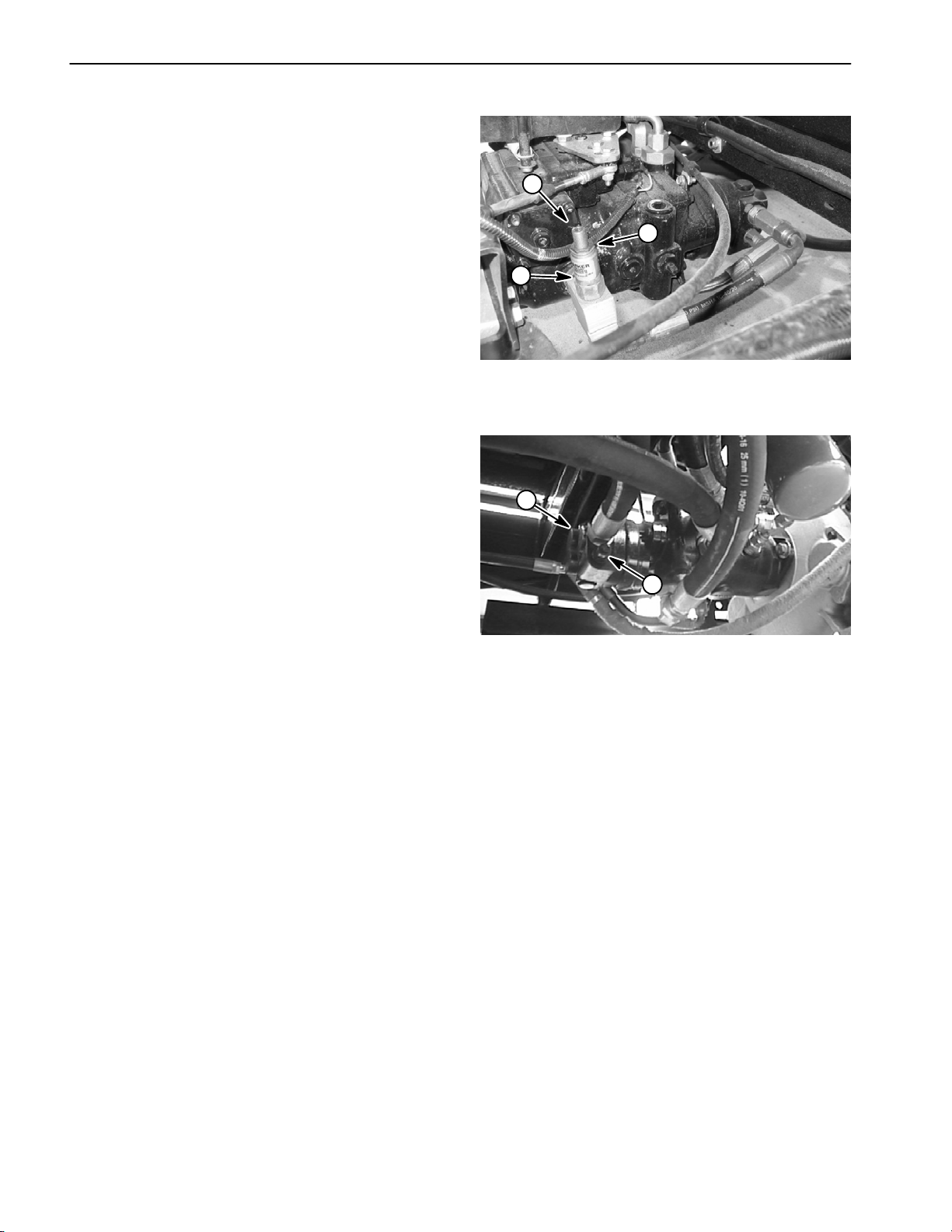
Adjust Relief Valve
The spray pump drive circuit relief valve is located on the
left side of the piston (traction) pump (Fig. 26). The
steering circuit relief valve is located under the suction
hose on the right side of the gear pump (Fig. 27). Relief
pressure should be tested before and after adjusting the
relief valve (see Steering Circuit Relief Pressure Test
and Spray Pump Drive Circuit Relief Pressure Test in the
Testing section of this chapter). Adjustment of the relief
valve can be performed as follows:
NOTE: Do not remove the relief valve for adjustment.
NOTE: To gain access to the adjustment socket and
jam nut on the steering circuit relief valve, remove plastic
cap.
1. To increase relief pressure setting, loosen jam nut
on relief valve and turn the adjustment socket on the relief valve in a clockwise direction. A 1/8 turn on the socket will make a measurable change in relief pressure.
Tighten jam nut after adjustment.
2. To decrease pressure setting, loosen jam nut on relief valve and turn the adjustment socket on the relief
valve in a counterclockwise direction. A 1/8 turn on the
socket will make a measurable change in relief pressure. Tighten jam nut after adjustment.
1
2
Figure 26
1. Spray circuit relief valve
2. Relief valve body
2
3
3. Jam nut
1
3. Recheck spray pump drive circuit relief pressure and
readjust as needed.
Figure 27
1. Steering relief valve 2. Gear pump
Rev. D
Multi Pro 5700--DHydraulic System Page 4 -- 26
Page 61

Service and Repairs
General Precautions for Removing and Installing Hydraulic System Components
Before Repair or Replacement of Components
1. Before removing any parts from the hydraulic system, park machine on a level surface, engage parking
brake, and stop engine. Remove key from the ignition
switch.
2. Clean machine before disconnecting, removing, or
disassembling any hydraulic components. Make sure
hydraulic components, hoses connections, and fittings
are cleaned thoroughly. Always keep in mind the need
for cleanliness when working on hydraulic components.
CAUTION
Rotate steering wheel and depress traction pedal in both forward and reverse to relieve hydraulic system pressure and to avoid injury from
pressurized hydraulic oil.
3. After turning engine off, operate all hydraulic controls
to relieve hydraulic system pressure.
4. Put caps or plugs on any hydraulic lines, hydraulic fittings, and components left open or exposed to prevent
contamination.
After Repair or Replacement of Components
1. Check oil level in the hydraulic reservoir and add correct oil if necessary. Drain and refill hydraulic reservoir
and change oil filter if component failure was severe or
system is contaminated (see Flush Hydraulic System).
2. Lubricate O–rings and seals with clean hydraulic oil
before installing hydraulic components.
3. Make sure caps or plugs are removed from the hydraulic fittings and components before reconnecting.
4. Use proper tightening methods when installing hydraulic hoses and fittings (see Hydraulic Fitting Installation).
5. After repairs, check control linkages and cables for
proper adjustment, binding, or broken parts.
6. After disconnecting or replacing any hydraulic component(s), operate machine functions slowly until air is
out of system (see Charge Hydraulic System).
7. Check for hydraulic oil leaks. Shut off engine and correct leaks if necessary. Check oil level in hydraulic reservoir and add correct oil if necessary.
System
Hydraulic
5. Put labels on disconnected hydraulic lines and
hoses for proper installation after repairs are completed.
6. Note the position of hydraulic fittings (especially elbow fittings) on hydraulic components before removal.
Mark parts if necessary to make sure they will be aligned
properly when reinstalling hydraulic hoses.
Check Hydraulic Lines and Hoses
WARNING
Keep body and hands away from pin hole leaks
or nozzles that eject hydraulic fluid under high
pressure. Use paper or cardboard, not hands, to
search for leaks. Hydraulic fluid escaping under
pressure can have sufficient force to penetrate
the skin and cause serious injury. If fluid is injected into the skin, it must be surgically removed within a few hours by a doctor familiar
with this type of injury. Gangrene may result from
such an injury.
Check hydraulic lines and hoses daily for leaks, kinked
lines, loose mounting supports, wear, loose fittings,
weather deterioration and chemical deterioration. Make
all necessary repairs before operating.
Multi Pro 5700–D Page 4 – 27 Hydraulic System
Page 62

Flush Hydraulic System
IMPORTANT: Flush the hydraulic system any time
there is a severe component failure or the system is
contaminated. Contaminated oil appears milky,
black, or contains metal particles.
1. Make sure hydraulic oil warm by operating the machine for several minutes. Park machine on a level surface. Stop engine, apply parking brake, and remove key
from ignition switch.
2. Clean area around hydraulic filter mounting area and
remove filter (see Operator ’s Manual). Drain filter into a
suitable container. Properly dispose removed filter.
3. Drain hydraulic reservoir into a s uitable c ontainer
(see Operator’s Manual).
4. Drain hydraulic system. Drain all hoses and components while the system is warm.
5. Make sure filter mounting surface is clean. Apply
clean hydraulic oil to gasket on new filter. Screw filter
onto filter head until gasket contacts mounting surface,
then tighten filter 3/4 turn further.
6. Reinstall all hoses and hydraulic components.
NOTE: Use only hydraulic fluids specified in Operator’s
Manual. Other fluids could cause system damage.
7. Fill hydraulic oil reservoir (see Operator’s Manual).
8. Disconnect wire harness electrical connector from
the engine fuel stop solenoid to prevent the engine from
starting.
9. Make sure traction pedal is in neutral.. Turn ignition
key switch to start; engage starter for ten (10) seconds
to prime hydraulic pumps. Wait fifteen (15) seconds to
allow the starter motor to cool and then repeat cranking
procedure again.
10.Connect wire harness electrical connector to fuel
stop solenoid to allow engine to start.
11. Start engine and run at low idle speed (1200 -- 1250
RPM) for a minimum of two (2) minutes.
12.Increase engine speed to high idle (3050 -- 3150
RPM) for minimum of one (1) minute under no load.
13.Turn steering wheel in both directions several times.
14.Shut off engine and check for hydraulic oil leaks.
Check oil level in hydraulic reservoir and add correct oil
if necessary.
15.Operate the machine for two (2) hours under normal
operating conditions.
16.Check condition of hydraulic oil. If the fluid shows any
signs of contamination repeat steps 1 through 12 again.
17.Resume normal operation and follow recommended
maintenance intervals.
Rev. D
Multi Pro 5700--DHydraulic System Page 4 -- 28
Page 63

Charge Hydraulic System
NOTE: When initially starting the hydraulic system with
new or rebuilt components such as motors or pumps, it
is important that the hydraulic system be charged properly. Air must be purged from the system and its components to reduce the chance of damage.
IMPORTANT: Change hydraulic oil filter whenever
hydraulic components are repaired or replaced.
1. Position machine on a level surface, engage parking
brake and remove key from the ignition switch.
2. Make sure all hydraulic connections, lines, and components are tight.
3. If component failure was severe or the system is contaminated, flush and refill hydraulic system and reservoir (see Flush Hydraulic System in this section).
4. Make sure hydraulic reservoir is full. Add correct hydraulic oil if necessary (see Operator’s Manual).
5. Check control cable to the piston (traction) pump for
proper adjustment, binding, or broken parts.
6. Disconnect wire harness electrical connector from
the engine fuel stop solenoid to prevent the engine from
starting.
11. After the hydraulic system starts to show signs of fill,
rotate steering wheel until the steering cylinder rod
moves in and out several times. If the cylinder rod does
not move after 15 seconds, or the gear pump emits abnormal sounds, shut the engine off immediately and determine cause or problem. Inspect for the following:
A. Loose filter or suction lines.
B. Blocked suction line.
C. Faulty charge relief valve.
D. Faulty gear pump.
12.If cylinder does move in 15 seconds, proceed to
step 13.
13.Operate the traction pedal in the forward and reverse
directions. The rear wheels should rotate in the proper
direction.
A. If the wheels rotate in the wrong direction, stop
engine, remove lines from side of piston (traction)
pump, and reverse the connections.
B. If the wheels rotate in the proper direction, stop
engine.
System
Hydraulic
7. Make sure traction pedal is in neutral.. Turn ignition
key switch to start; engage starter for ten (10) seconds
to prime hydraulic pumps. Wait fifteen (15) seconds to
allow the starter motor to cool and then repeat cranking
procedure again.
8. Connect wire harness electrical connector to fuel
stop solenoid to allow engine to start.
WARNING
Before jacking up the machine, review and follow
Jacking Instructions in Chapter 1 -- Safety.
9. Raise rear wheels off the ground, and place support
blocks under the frame. Chock front wheels to prevent
movement of the machine.
10.Start engine and run it at low idle (1200 -- 1250 RPM).
The charge pump should pick up oil and fill the hydraulic
system. If there is no indication of fill in 30 seconds, stop
the engine and determine the cause.
14.Adjust traction pedal to the neutral position (see Operator’s Manual).
15.Check operation of the neutral switch (see Operator’s Manual).
16.Remove blocks from frame and lower machine to the
ground. Remove chocks from front wheels.
17.If the piston (traction) pump or a wheel motor was replaced or rebuilt, run the machine so wheels turn slowly
for 10 minutes.
18.Operate machine by gradually increasing it’s work
load to full over a 10 minute period.
19.Stop the machine. Check hydraulic reservoir and fill
if necessary. Check hydraulic components for leaks and
tighten any loose connections.
Multi Pro 5700--D Hydraulic SystemPage 4 -- 29
Rev. D
Page 64

Gear Pump
LEFT SIDE OF PUMP
15
12
14
13
11
9
8
12
10
1
NOTE: ILLUSTRATION FROM
BOTTOM OF MACHINE
1. Piston (traction) pump
2. O–ring
3. Gear pump
4. O–ring
5. Hydraulic hose (gear pump suction)
6
5
4
Figure 26
6. Cap screw (2 used)
7. Flat washer (2 used)
8. O–ring
9. Hydraulic hose (to steering control)
10. O–ring
2
7
3
11. Hydraulic tee fitting
12. O–ring
13. Hydraulic hose (to PWM valve)
14. Hydraulic hose (to relief valve)
15. Relief valve assembly
Multi Pro 5700–DHydraulic System Page 4 – 30
Page 65

Removal (Fig. 26)
1. Park machine on a level surface, stop engine, engage parking brake, and remove key from the ignition
switch.
2. To prevent contamination of hydraulic system during
gear pump removal, thoroughly clean exterior of pump
assembly.
4. Install new hydraulic oil filter and fill hydraulic reservoir with correct oil (see Operator’s Manual).
5. Properly fill hydraulic system (see Charge Hydraulic
System in the Service and Repairs section of this chapter).
6. Stop engine and check for hydraulic oil leaks. Check
hydraulic reservoir oil level.
CAUTION
Rotate steering wheel and depress traction pedal in both forward and reverse to relieve hydraulic system pressure and to avoid injury from
pressurized hydraulic oil.
3. Operate all hydraulic controls to relieve hydraulic
system pressure.
4. Read the General Precautions for Removing and
Installing Hydraulic System Components at the beginning of the Service and Repairs section of this chapter.
NOTE: To ease reassembly, tag hydraulic hoses to
show their correct position on the gear pump.
5. Put drain pan below the gear pump. Remove hydraulic hoses and fittings connected to gear pump. Put plugs
or caps on disconnected hydraulic hoses and open
ports of pump to prevent contamination of the system.
6. Support the gear pump to prevent it from falling (Fig.
27). Remove two (2) cap screws and flat washers retaining gear pump to piston pump.
2
Figure 27
1. Gear pump 2. Piston pump
1
System
Hydraulic
7. Carefully pull gear pump from piston pump and lower
it out of the machine. Locate and retrieve o–ring from between pumps.
Installation (Fig. 26)
1. Lubricate new o–ring and position it to gear pump.
Carefully raise gear pump and position it to the piston
pump.
2. Align spline teeth and slide gear pump input shaft
into piston pump coupling. Support gear pump to prevent it from falling while installing two (2) cap screws and
flat washers securing gear pump to piston pump.
3. Remove plugs or caps from disconnected hydraulic
hoses and ports of the gear pump. Lubricate new o–
rings and install fittings and hoses to correct location on
gear pump.
Multi Pro 5700–D Page 4 – 31 Hydraulic System
Page 66

Gear Pump Service
8
2
6
1
21 to 24 ft–lb
(29 to 33 N–m)
14
15
16
21
22
10
3
4
11
25 to 28 ft–lb
(34 to 38 N–m)
7
5
7
9
12
17
13
30 to 34 ft–lb
(41 to 46 N–m)
19
20
18
23
15
24
21 to 24 ft–lb
(29 to 33 N–m)
Figure 28
1. Cap screw (8 used)
2. Washer (4 used)
3. Shaft seal
4. Washer
5. Front plate
6. Plug
7. O–ring
8. Backup gasket
9. Pressure seal
10. Wear plate
11. Drive gear
12. Idler gear
13. Body
14. Plug
15. O–ring
16. Backplate
NOTE: For service of the gear pump, see the Eaton
Model 26000 Single Gear Pumps Repair Information at
the end of this chapter.
17. Steering relief valve
18. O–ring
19. Backup washer
20. O–ring
21. Flow divider spool
22. Spring
23. Disc
24. Plug
Hydraulic System Page 4 – 32 Multi Pro 5700–D
Page 67

This page is intentionally blank.
System
Hydraulic
Multi Pro 5700–D Page 4 – 33 Hydraulic System
Page 68

Piston (Traction) Pump
39
38
37
36
32
2
40
26
34
33
32
35
31
30
4
27
22
LEFT SIDE OF PUMP
NOTE: ILLUSTRATION FROM
BOTTOM OF MACHINE
29
28
4
21
22
20
19
1
25
4
7
8
4
7
Lubricant
5
3
Antiseize
2
7
13
23
4
24
9
17
16
11
15
14
7
12
10
7
18
9
6
9
1. Piston (traction) pump
2. O--ring
3. Hydraulic adapter
4. O--ring
5. Hydraulic tee fitting
6. Hydraulic hose (to reservoir)
7. O--ring
o
hydraulic fitting
8. 90
9. O--ring
10. Hydraulic hose (piston pump suction)
11. O -- ring
12. Gear pump
13. Hydraulic hose (gear pump suction)
14. Cap screw (2 used)
15. Flat washer (2 used)
16. Hydraulic hose (to LH wheel motor)
17. Hydraulic hose (to RH wheel motor)
o
hydraulic fitting
18. 45
19. Straight fitting
20. O--ring
21. Hydraulic hose (to oil filter)
22. O--ring
o
hydraulic fitting
23. 90
24. Hydraulic hose (from oil filter)
25. Hydraulic hose (from wheel motors)
26. Hydraulic hose (to steering control)
27. Hydraulic tee fitting
Removal (Fig. 31)
1. Park machine on a level surface, stop engine, engage parking brake, and remove key from the ignition
switch.
2. To prevent contamination of hydraulic system during
pump removal, thoroughly clean exterior of pump assembly.
Figure 31
28. Hydraulic hose (to PWM valve)
29. Hydraulic hose
30. O--ring
o
hydraulic fitting
31. 90
32. O--ring
33. Seal kit
34. Relief valve
35. Relief valve body
36. Hydraulic adapter
37. Cap screw (2 used)
38. Lock washer (2 used)
39. Flat washer (2 used)
40. O--ring
CAUTION
Rotate steering wheel and depress traction pedal in both forward and reverse to relieve hydraulic system pressure and to avoid injury from
pressurized hydraulic oil.
Multi Pro 5700--DHydraulic System Page 4 -- 34
Page 69

3. Operate all hydraulic controls to relieve hydraulic
system pressure.
6. Connect two (2) wires to neutral switch on piston
pump (Fig. 32).
4. Remove traction cable ball joint from control plate on
piston pump by removing lock nut (Fig. 32). Remove cap
screw from control plate. Locate and retrieve three (3)
flat washers (Fig. 33).
5. Disconnect two (2) wires from neutral switch on piston pump (Fig. 32).
6. Remove flange head screw and flange nut that secures R--clamp and right side brake cable to pump assembly (Fig. 32).
7. Read the General Precautions for Removing and
Installing Hydraulic System Components at the beginning of the Service and Repairs section of this chapter.
NOTE: To ease reassembly, tag hydraulic hoses to
show their correct position on the pump assembly.
8. Put a drain pan below the pump assembly. Remove
hydraulic hoses and fittings connected to piston and
gear pumps. Put plugs or caps on disconnected hydraulic hoses to prevent contamination of the system. Put
plugs in open ports of pumps.
9. Support the pump assembly to prevent it from falling.
Remove two (2) cap screws, lock washers and flat
washers that retain pump assembly to engine bell housing.
7. Remove plugs or caps from disconnected hydraulic
hoses and ports of the pump assembly. Lubricate new
O--rings and install fittings and hoses to correct location
on gear and piston pumps.
8. Secure R--clamp and right side brake cable to pump
assembly with flange head screw and flange nut.
9. Install new hydraulic oil filter and fill hydraulic reservoir with correct oil (see Operator’s Manual).
10.Properly fill hydraulic system (see Charge Hydraulic
System in the Service and Repairs section of this chapter).
11. Stop engine and check for hydraulic oil leaks. Check
hydraulic reservoir oil level.
4
1
2
3
System
Hydraulic
10.Carefully pull pump assembly from engine and lower
it out of the machine.
11. If needed, separate gear pump from piston pump
(see Gear Pump Removal in this section).
Installation (Fig. 31)
1. If gear pump w as removed from piston pump, install
gear pump to piston pump (see Gear Pump Installation
in this section).
2. Apply antiseize lubricant to piston pump shaft
splines.
3. Carefully raise pump assembly and position it to the
engine. Make sure that both bushings on control plate
are between centering arms on rear of engine (Fig. 32).
4. Align spline teeth and slide piston pump input shaft
into engine coupling spline. Support pump to prevent it
from falling while installing two (2) cap screws, lock
washers and flat washers to secure pump to engine bell
housing.
5. Secure traction cable to control plate with cap screw,
three ( 3) washers and lock nut (Fig. 32 and 33).
Figure 32
1. Traction cable lock nut
2. Neutral switch
6
7
Figure 33
1. Cap screw
2. Flat washer
3. Neutral plate
4. Flat washer
3. R--clamp/brake cable
4. Centering arm
1
2
3
4
5
5. Lock nut
6. Ball joint
7. Traction cable
Multi Pro 5700--D Hydraulic SystemPage 4 -- 35
Page 70

Piston (Traction) Pump Service
34
36
34
35
39
38
41
40
24
25
18
17
54
27
26
27
28
37
30
33
32
31
29
48
10
20
11
47
46
19
21
44
22
43
42
23
49
50
15
14
53
12
10
9
8
1
51
52
19
20
45
5
6
7
6
45
2
3
12
Figure 32
1. Drive shaft
2. Retaining ring
3. Shaft seal
4. Washer
5. Retaining ring
6. Thrust bearing race
7. Thrust bearing
8. Bearing
9. Housing
10. Seal set
11. Servo piston
12. Gasket
13. Cover plate
14. Flat washer (4 used per cover)
15. Socket head screw (4 used per cover)
16. Washer
17. Jam nut
18. Seal washer
19. Plug
20. O–ring
21. Cradle
22. Bushing
23. Screw
24. Valve plate
25. Bearing
26. Reverse relief valve
27. O–ring
28. O–ring
29. Bypass valve
30. Key
31. Geroter (inner)
32. O–ring
33. Geroter (outer)
34. Flat washer (4 used)
35. Cap screw (3 1/2” long: 2 used)
36. Cap screw (4” long: 2 used)
NOTE: For service of the piston (traction) pump, see
the Eaton Model 72400 Servo Controlled Piston Pump
Repair Information at the end of this chapter.
13
14
15
16
37. Charge pump adapter
38. Backplate
39. Roll pin
40. Housing gasket
41. Rotating kit
42. Camplate
43. Servo piston follower
44. Cap screw (2 used)
45. Bushing dowel (2 used)
46. Socket head screw (6 used)
47. Control arm
48. Hex nut
49. Lock washer
50. Manual servo control assembly
51. Control orifice (3 used)
52. Housing gasket
53. Cover plate
54. Forward relief valve
Multi Pro 5700–DHydraulic System Page 4 – 36
Page 71

Manual Servo Control Assembly
44 to 52 ft–lb
(60 to 70 N–m)
1
2
3
4
5
17 to 26 in–lb
(1.9 to 2.9 N–m)
1. Plug
2. O–ring
3. Retaining ring
4. Spring retainer
5. Spring
6. Spool valve
7. Control housing
8. Input shaft
10
15
14
7
9
13
12
4
8
6
16
24
Loctite #222
23
11
17
22
28 to 34 in–lb
21
(3.2 to 3.8 N–m)
Loctite #242
20
18
19
System
Hydraulic
Figure 33
9. O–ring
10. Wiper seal
11. O–ring
12. Adaptor
13. Ball
14. Pin
15. Neutral switch
16. O–ring
17. Set screw
18. Set screw
19. Pin
20. Retaining ring
21. Feedback link
22. Dowel pin
23. Bell crank
24. Set screw
NOTE: For service of the manual servo control assem-
bly (including neutral switch adjustment), see the Eaton
Model 72400 Servo Controlled Piston Pump Repair Information at the end of this chapter.
Multi Pro 5700–D Page 4 – 37 Hydraulic System
Page 72

Wheel Motors
1
2
3
4
70 to 90 ft–lb
5
(95 to 122 N–m)
1. Planetary assembly
2. Lug nut (8 used per wheel)
3. Tire and wheel assembly
4. Gasket
5. RH brake assembly
6. Flange head screw (4 used per brake)
7. Splined brake shaft
8. Retaining ring
9. O–ring
10. RH wheel motor
11. Flat washer (2 used per motor)
30
31
60 ft–lb
(81 N–m)
24
6
22
23
20
25
21
19
13
17
20
18
7
9
8
14
13
12
10
11
Figure 34
12. Cap screw (2 used per motor)
13. O–ring
14. Hydraulic tee fitting
15. Hyd. hose (to top pump fitting)
16. O–ring
17. Hydraulic adapter
18. O–ring
19. Hydraulic hose (to pump case drain)
20. O–ring
21. O–ring
14
13
16
16
60 ft–lb
(81 N–m)
29
21
28
9
27
13
17
18
25
26
LEFT
FRONT
15
22. Hydraulic adapter
23. Hydraulic tee fitting
24. Hydraulic hose
25. Hydraulic hose
26. Hyd. hose (to bottom pump fitting)
27. LH wheel motor
28. LH brake cable
29. LH brake assembly
30. Flange head screw (6 used per side)
31. RH brake cable
Multi Pro 5700–DHydraulic System Page 4 – 38
Page 73

Removal (Fig. 34)
1. Park machine on a level surface, stop engine, engage parking brake, and remove key from the ignition
switch.
5. Remove plugs from hydraulic lines, fittings, and
ports. Lubricate new o–rings and attach hydraulic hoses
to wheel motor.
6. If right side wheel motor was removed, plug speed
sensor connector into machine wiring harness.
CAUTION
Rotate steering wheel and depress traction pedal in both forward and reverse to relieve hydraulic system pressure and to avoid injury from
pressurized hydraulic oil.
2. Operate all hydraulic controls to relieve hydraulic
system pressure.
3. Read the General Precautions for Removing and
Installing Hydraulic System Components at the beginning of the Service and Repairs section of this chapter.
4. To prevent contamination of hydraulic system during
motor removal, thoroughly clean exterior of motor and
fittings.
NOTE: To ease reassembly, tag the hydraulic hoses to
show their correct position on the wheel motor.
5. Disconnect hydraulic hoses from fittings on wheel
motor. Put caps or plugs on hydraulic lines, fittings, and
ports to prevent contamination.
7. Check fluid level in hydraulic oil reservoir and adjust
as required (see Operator’s Manual).
8. Operate machine and inspect for leaks.
3
Figure 35
1. Splined brake shaft step 3. Planetary assembly end
2. Hydraulic motor end
2
2
1
1
System
Hydraulic
6. If right side wheel motor is being removed, unplug
speed sensor connector from machine wiring harness.
IMPORTANT: Before loosening fasteners, support
wheel motor to prevent motor from falling.
7. Support the pump assembly to prevent it from falling.
Remove two (2) cap screws and flat washers that secure
wheel motor to brake and planetary assemblies. Remove wheel motor from machine.
Installation (Fig. 34)
1. If splined brake shaft was removed from brake assembly, make sure that the stepped end of the shaft is
aligned toward the hydraulic wheel motor (Fig. 35). Also,
make sure that splines engage rotating discs in brake
assembly.
2. Position wheel motor to brake assembly.
3. Align splines on motor shaft and splined brake shaft.
Slide motor to brake assembly.
4. Secure motor to brake and planetary assemblies
with cap screws and flat washers. Torque cap screws 60
ft–lb (81 N–m).
3
4
Figure 36
1. Piston (traction) pump 3. Bottom pump fitting
2. Top pump fitting 4. Case drain fitting
Multi Pro 5700–D Page 4 – 39 Hydraulic System
Page 74

Wheel Motor Service
7
15 to 18 ft–lb
(20 to 24 N–m)
8
1
2
20
3
4
5
6
5
4
9
12
18
19
10
11
13
14
15
16
17
21
Figure 37
1. Retaining ring
2. Shaft seal
3. Washer
4. Retaining ring
5. Thrust bearing race
6. Thrust bearing
7. Drive shaft
8. Cap screw (6 used)
9. Back plate
10. Dowel pin
11. Dowel pin (3 used)
12. O–ring
13. Needle bearing
14. Valve plate
NOTE: The wheel motors used on the Multi Pro
5700–D are very similar. The major difference is the
speed sensor installed in the right side wheel motor. Service of the left and right motors requires the same procedure.
NOTE: For service of the wheel motors, see the Eaton
Model 74318 and 74348 Piston Motors: Fixed Displacement, Valve Plate Design Repair Information at the end
of this chapter.
15. Rotating kit
16. Cam plate insert
17. Housing
18. Speed sensor (RH wheel)
19. O–ring
20. O–ring
21. Needle bearing
NOTE: For information on speed sensor installation,
see Traction Speed Sensor in the Service and Repairs
section of Chapter 5 – Electrical System.
Hydraulic System Page 4 – 40 Multi Pro 5700–D
Page 75

This page is intentionally blank.
System
Hydraulic
Multi Pro 5700–D Page 4 – 41 Hydraulic System
Page 76

Spray Pump Drive Motor
1
2
Antiseize
Lubricant
3
9
10
Loctite #242
4
6
5
7
9
8
10
Loctite #242
13
14
15
12
16
FRONT
RIGHT
26
8
6
21
11
4
2
Antiseize
Lubricant
17
18
19
20
21
22
23
24
25
26
22
1. Spray pump assembly
2. Flange nut
3. Square key
4. Lock nut
5. Pump hub
6. Coupler spacer
7. Rubber coupling
8. Flat washer
9. Cap screw
Figure 40
10. Set screw
11. Hydraulic motor hub
12. Flange head screw
13. Rear guard plate
14. Front guard plate
15. Flange nut
16. PWM Valve
17. Pump mount bracket
18. Flange head screw (4 used)
27
19. Woodruff key
20. Hydraulic motor
21. Hydraulic hose (from PWM CF port)
22. O--ring
23. Hydraulic 90
24. O--ring
25. Hydraulic 90
26. Hydraulic hose (to T fitting on PWM)
27. U--bolt (2 used)
o
fitting (short)
o
fitting (long)
Multi Pro 5700--DHydraulic System Page 4 -- 42
Page 77

Removal (Fig. 40)
1. Park machine on a level surface, stop engine, engage parking brake, and remove key from the ignition
switch.
2. If motor hub was removed, apply antiseize lubricant
to motor shaft. Install woodruff key in shaft and slide hub
onto motor shaft.
3. Position motor on pump mounting bracket and install
flange head screws and flange nuts to motor and mounting bracket. Leave fasteners loose.
CAUTION
Rotate steering wheel and depress traction pedal in both forward and reverse to relieve hydraulic system pressure and to avoid injury from
pressurized hydraulic oil.
2. Operate all hydraulic controls to relieve hydraulic
system pressure.
3. Read the General Precautions for Removing and
Installing Hydraulic System Components at the beginning of the Service and Repairs section of this chapter.
4. Remove flange head screw and flange nut that secure front and rear guard plate. Remove four (4) flange
nuts that retain guard plates to pump mount bracket. Remove guard plates from machine.
5. Label all hydraulic connections to ease reassembly.
Clean hydraulic hose ends prior to disconnecting the
hoses from hydraulic motor.
6. Disconnect hydraulic hoses from motor. Allow hoses
to drain into a suitable container.
7. Put caps or plugs on disconnected hoses and fittings
to prevent contamination.
8. Remove lock nuts, flat washers, cap screws, and
coupler spacers that secure rubber coupling to hydraulic
motor hub.
9. Remove two (2) flange head screws and flange nuts
that secure hydraulic motor to pump mount bracket.
4. Place coupling spacers into rubber coupling. Install
cap screws, flat washers, and lock nuts to secure rubber
coupling to motor hub. Make sure that cap screw
threads extend through lock nut.
5. If motor hub was removed, apply Loctite #242 (or
equivalent) to threads of motor hub set screws. Install
set screws into hub to secure hub to motor shaft.
6. Turn pump shaft by hand and position motor on
mounting bracket to best align the coupling assembly
between the pump shaft and the hydraulic motor shaft.
7. Secure motor to mounting bracket by tightening
flange head screws and flange nuts.
8. Lubricate new O--rings and install hydraulic hoses to
correct hydraulic fittings on motor.
9. Position front and rear guard plates to pump mount
bracket. Install and tighten flange head screw and
flange nut to guard plates. Install flange nuts to secure
guard plates to pump mount bracket.
10.Check fluid level in hydraulic oil reservoir and adjust
as required (see Operator’s Manual).
11. Properly fill hydraulic system (see Charge Hydraulic
System in the Service and Repairs section of this chapter).
12.Stop engine and check for hydraulic oil leaks. Check
hydraulic reservoir oil level.
System
Hydraulic
10.Remove hydraulic motor from machine.
11. If needed, loosen set screws in hydraulic motor hub.
Pull hub from motor shaft. Locate and remove woodruff
key from motor shaft. Remove set screws from hub.
Clean threads of set screws and hub.
12.If hydraulic fitting removal is needed, note orientation
of hydraulic fittings before removing fittings from motor.
Installation (Fig. 40)
1. If removed, lubricate new O--rings and install hydraulic fittings to motor.
Multi Pro 5700--D Hydraulic SystemPage 4 -- 43
1
3
2
Figure 41
1. Spray pump drive motor
2. Hydraulic hose (from PWM CF port)
3. Hydraulic hose (to PWM EX port)
Page 78

Spray Pump Drive Motor Service
22
21
20
6
19
18
17
16
15
14
13
10
9
12
8
6
7
3
6
2
1
22 to 26 ft–lb
(30 to 35 N–m)
4
5
Figure 40
1. Cap screw (5 used)
2. End cover
3. Commutator seal
4. Commutator
5. Commutator ring
6. Ring seal
7. Manifold
8. Stator
9. Vane
10. Rotor
11. Wear plate
12. Drive link
13. Shaft
14. Woodruff key
15. Bearing
NOTE: For service of the spray pump drive motor, see
the Parker Torqlink
TM
Service Procedure at the end of
this chapter.
6
11
16. Thrust bearing
17. Thrust washer
18. Inner seal
19. Backup washer
20. Housing
21. Bearing
22. Seal
Hydraulic System Page 4 – 44 Multi Pro 5700–D
Page 79

Relief Valve
Removal
1. Park machine on a level surface, stop engine, engage parking brake, and remove key from the ignition
switch.
CAUTION
Rotate steering wheel and depress traction pedal in both forward and reverse to relieve hydraulic system pressure and to avoid injury from
pressurized hydraulic oil.
2. Operate all hydraulic controls to relieve hydraulic
system pressure.
3. Read the General Precautions for Removing and
Installing Hydraulic System Components at the beginning of the Service and Repairs section of this chapter.
4. Disconnect hose assembly from hydraulic fitting at
bottom of relief valve body. Allow hose to drain into a
suitable container.
5. Unscrew relief valve body from hydraulic adapter in
side of piston pump.
6. If needed, remove hydraulic fitting from bottom of relief valve body.
Installation
1. Lubricate new o–rings with clean hydraulic fluid.
A. Contamination may cause valves to stick or hang
up. Contamination can become lodged in small valve
orifices or seal areas causing malfunction.
B. If sealing surfaces appear pitted or damaged, the
hydraulic system may be over heating or there may
be water in the hydraulic system.
CAUTION
Use eye protection such as goggles when using
compressed air.
4. Clean relief valve cartridge using clean mineral spirits to flush out any contamination. Submerge cartridge
in clean mineral spirits to flush out contamination. Particles as fine as talcum powder can affect the operation
of relief valve. Use compressed air for cleaning.
Reassembly
1. Lubricate new o–ring and back–up ring with clean
hydraulic fluid. Install o–ring and back–up ring to the relief valve cartridge.
2. Carefully thread relief valve cartridge into the relief
valve body. The valve should go in easily without binding. Torque cartridge to 190 in–lb (21.4 N–m).
3. Lubricate new O–rings with clean hydraulic fluid.
Connect hydraulic fittings and O–rings to the relief valve
body.
System
Hydraulic
2. If removed, install hydraulic fitting into bottom of relief valve body.
3. Secure valve body to the hydraulic adapter in side of
piston pump.
4. Install hydraulic hose to hydraulic fitting at bottom of
relief valve body. Tighten hose connections.
Disassembly
1. Unscrew relief valve cartridge from the relief valve
body. Remove o–ring and back–up ring.
2. Inspect ports of the relief valve body for damaged
sealing surfaces or threads and contamination.
3. Inspect relief valve cartridge for damaged sealing
surfaces and contamination.
Multi Pro 5700–D Hydraulic SystemPage 4 – 45
2
1
1. Pump assembly
2. O–ring
3. Hydraulic adapter
4. O–ring
5. Relief valve body
5
3
4
Figure 41
6
190 in–lb
(21.5 N–m)
7
8
9
10
6. Relief cartridge
7. Seal kit
8. Hydraulic fitting
9. O–ring
10. Hydraulic hose
Page 80

Pulse Width Modulated (PWM) Valve
8
9
13
FRONT
RIGHT
11
12
15
14
10
10
1
5
4
9
16
17
3
8
2
7
18
6
5
19
20
Figure 44
1. Spray pump assembly
2. Flange nut
3. Flange head screw
4. Rear guard plate
5. Flange nut (3 used)
6. Front guard plate
7. Hydraulic hose (PWM to motor)
8. O--ring
9. Hydraulic fitting
10. O--ring
11. Cap screw (2 used)
12. PWM Valve
13. Hydraulic hose (from gear pump)
14. Hydraulic tee fitting
The Pulse Width Modulated (PWM) Valve is used on the
Multi Pro 5700-- D to control gear pump flow to the spray
pump hydraulic motor. Electrical current to the PWM
Valve solenoid coil affects the internal spool setting of
the Valve and thus the hydraulic flow to the spray pump
motor.
For information on PWM Valve solenoid testing, see
Pulse Width Modulated (PWM) Valve Solenoid in the
Component Testing section of Chapter 5 -- Electrical
System.
7
17
15. Hydraulic hose (to oil cooler)
16. O--ring
17. Hydraulic hose (motor to PWM tee)
18. Flat washer (2 used)
19. Hydraulic motor
20. Pump mount bracket
IMPORTANT: Correct operation of the PWM Valve
depends on precise assembly and adjustment. No
disassembly or adjustment of the PWM Valve is recommended.
Internal parts for the PWM valve are not available. On
machines with serial numbers above 260000300, the
PWM valve solenoid coil is available as a separate component. Refer to your parts catalog for replacement part
information.
Rev. D
Multi Pro 5700--DHydraulic System Page 4 -- 46
Page 81

Removal (Fig. 38)
1. Park machine on a level surface, stop engine, engage parking brake, and remove key from the ignition
switch.
CAUTION
Rotate steering wheel and depress traction pedal in both forward and reverse to relieve hydraulic system pressure and to avoid injury from
pressurized hydraulic oil.
2. Operate all hydraulic controls to relieve hydraulic
system pressure.
3. Read the General Precautions for Removing and
Installing Hydraulic System Components at the beginning of the Service and Repairs section of this chapter.
4. Label all hydraulic connections to ease reassembly.
Clean hydraulic hose ends prior to disconnecting the
hoses from PWM Valve.
5. Disconnect four (4) hydraulic hoses from fittings in
PWM Valve. Allow hoses to drain into a suitable container.
1
3
2
Figure 43
1. PWM Valve 3. Solenoid connector
2. Solenoid
1
2
4
3
System
Hydraulic
6. Put caps or plugs on disconnected hoses and fittings
to prevent contamination.
7. Disconnect PWM Valve solenoid connector from
machine wiring harness (Fig. 43).
8. Remove two (2) cap screws and flange nuts that secure PWM Valve to pump mount bracket. Locate and retrieve two (2) flat washers from between PWM Valve and
pump mount bracket. Remove PWM Valve from machine.
Installation (Fig. 38)
1. Place two (2) cap screws into PWM Valve mounting
holes. Install flat washer on screws and position Valve
to pump mount bracket. Install and tighten flange nuts
to secure PWM Valve to bracket.
2. Remove caps and plugs from hydraulic hoses and
fittings. Lubricate new o–rings and install hydraulic
hoses to fittings in PWM Valve.
3. Plug PWM Valve solenoid connector into machine
wiring harness.
Figure 44
1. IN port (from gear pump) 3. EX port (to oil cooler)
2. CF port (to motor) 4. Solenoid coil
4. Check fluid level in hydraulic oil reservoir and adjust
as required (see Operator’s Manual).
5. Operate machine and inspect for leaks.
Multi Pro 5700–D Page 4 – 47 Hydraulic System
Page 82

Steering Control Valve
9
10
20 to 26 ft--lb
(28to35N--m)
11
8
6
5
7
4
2
2
1
2
3
2
1
12
13
1. Hydraulic hose (to steering cylinder)
2. O--ring
3. Hydraulic hose (to oil cooler)
4. Hydraulic hose (from pump)
5. Steering control valve
Figure 46
6. Steering column
7. Cap screw (4 used)
8. Steering wheel
9. Steering wheel cover
FRONT
RIGHT
10. Nut
11. Dust cover
12. Steering seal
13. Steering cylinder
Rev. C
Multi Pro 5700--DHydraulic System Page 4 -- 48
Page 83

Removal (Fig. 45)
1. Park the machine on a level surface, engage parking
brake, and stop engine. Remove key from the ignition
switch.
3. Lubricate new o–rings and connect hydraulic hoses
to steering control valve (Fig. 46). Tighten hose connections.
4. Position dash panel to front hood and secure with
fasteners (Fig. 47).
CAUTION
Rotate steering wheel and depress traction pedal in both forward and reverse to relieve hydraulic system pressure and to avoid injury from
pressurized hydraulic oil.
2. Operate all hydraulic controls to relieve hydraulic
system pressure.
3. Read the General Precautions for Removing and
Installing Hydraulic System Components at the beginning of the Service and Repairs section of this chapter.
4. Label all hydraulic connections for reassembly purposes. Clean hydraulic hose ends prior to disconnecting
the hoses.
5. Remove fasteners that secure dash panel to front
hood (Fig. 47). Front edge of panel is secured with four
(4) screws and weldnuts. Sides of panel are fastened
with four (4) screws and flange nuts. Carefully slide dash
panel up steering column to allow access to steering
control valve.
6. Disconnect hydraulic hoses connected to the steering control valve. Allow hoses to drain into a suitable
container. Cap or plug openings of control valve and
hoses to prevent contamination.
5. Check fluid level in hydraulic oil reservoir and adjust
as required (see Operator’s Manual).
6. After assembly is completed, operate steering cylinder to verify that hydraulic hoses and fittings are not contacted by anything and that there are no leaks.
5
3
1
2
4
Figure 46
1. Steering control valve 4. Hyd hose (from pump)
2. Hyd hose (left turn) 5. Hyd hose (to oil cooler)
3. Hyd hose (right turn)
System
Hydraulic
7. Support steering control valve to prevent it from fal-
1
ling during removal.
2
8. Loosen and remove four (4) cap screws that secure
steering column and steering control valve to machine
3
frame.
9. Slide steering valve from control column. Remove
control valve from machine.
Installation (Fig. 45)
3
1. Slide steering control valve onto steering column.
Secure steering column and control valve to frame with
four (4) cap screws.
1. Steering column 3. Dash side screw
2. Dash front edge screw
Figure 47
2. Remove caps and plugs from disconnected hoses
and fittings.
Multi Pro 5700–D Page 4 – 49 Hydraulic System
Page 84

Steering Control Valve Service
8
1
2
3
150 in–lb
(17 N–m)
24
23
18
22
21
17
16
19
15
20
19
14
5
13
12
4
11
6
7
9
10
140 to 160 in–lb
(15.8 to 18.1 N–m)
Figure 48
1. Steering valve housing
2. Dust seal
3. O–ring
4. Spool
5. Spring retaining ring
6. Pin
7. Sleeve
8. Centering springs/spacers
9. Cap screw (7 used)
10. End cap
11. O–ring
12. Seal ring
13. O–ring
14. Geroter
15. O–ring
16. Spacer
Disassembly
NOTE: Cleanliness is extremely important when
repairing hydraulic components. Work in a clean area.
Before disassembly, drain the oil, then plug the ports
and thoroughly clean the exterior. During repairs,
always protect machined surfaces.
1. Remove the seven cap screws from the steering
valve assembly.
2. Remove end cap, geroter, spacer, geroter drive,
wear plate, seal ring, and o–rings (Items 11, 13, and 15)
from housing (Fig. 48).
3. Remove the plug, o–ring, and check ball from the
housing.
17. Geroter drive
18. Wear plate
19. Bearing race
20. Thrust bearing
21. Plug
22. O–ring
23. Check ball
24. Quad seal
4. Slide the spool and sleeve assembly from the housing.
5. Remove the thrust bearing and bearing races (2).
6. Remove the quad seal.
7. Use a small blade screwdriver to carefully pry the
dust seal from the housing. Be careful to not damage the
dust seal seat in the housing.
8. Remove the pin (Item 6) that holds the spool and
sleeve together.
9. Carefully slide the spool out of the sleeve. The centering springs and spring retaining ring will stay with the
spool as it is removed.
Hydraulic System Page 4 – 50 Multi Pro 5700–D
Page 85

CAUTION
8. Put the thrust bearing and bearing races into the
housing. The thrust bearing goes between the two bearing races (Fig. 49).
The centering springs are under tension. Remove the retaining ring carefully.
10.Remove the spring retaining ring and centering
springs from the spool.
Reassembly
Check all mating surfaces. Replace any parts with
scratches or burrs that could cause leakage. Wash all
metal parts in clean solvent. Blow them dry with pressurized air. Do not wipe parts dry with paper towels or cloth.
Lint in a hydraulic system will cause damage.
NOTE: Always use new seals and o–rings when
reassembling the steering control valve.
IMPORTANT: During reassembly, lubricate the new
seals with petroleum jelly. Also, lubricate machined
surfaces and bearings with clean hydraulic oil.
1. Install the quad seal:
A. Put one of the bearing races and sleeve into the
housing.
B. Together, the housing and bearing race create a
groove into which the quad seal will be installed.
C. Hold the bearing race tightly against the input end
of the housing by pushing on the gerotor end of the
sleeve.
D. Fit the quad seal into its seat through the input
end of the housing. Be sure the seal is not twisted.
IMPORTANT: Do not damage the dust or quad seals
when installing the spool and sleeve assembly.
9. Apply a light coating of clean hydraulic oil to the spool
and sleeve assembly. Carefully slide the assembly into
the housing.
10.Clamp the housing in a vise. Use only enough clamping force to hold the housing securely.
11. Lubricate and install a new o-ring (Item 3) in the
groove in the housing.
12.Install the wear plate and align screw holes in the
wear plate with threaded holes in the housing.
NOTE: The holes in the wear plate are symmetrical.
13.Install the geroter drive, making sure the slot in the
drive engages the pin.
14.Lubricate and install new o-ring in wear plate groove.
15.Install the gerotor and align the screw holes.
16.Lubricate and install new o-ring in gerotor ring
groove.
17.Lubricate and install new o-ring and seal ring in gerotor star groove.
18.Install the spacer.
19.Install the end cap and seven (7) cap screws. Tighten
the cap screws, in a crossing pattern, from 140 to 160
in-lb (15.8 to 18.1 N–m).
System
Hydraulic
E. Remove the sleeve and bearing race.
2. Lubricate and install the dust seal.
3. Install the centering springs in the spool. It is best to
install the two flat pieces first. Next, install the curved
pieces, three at a time.
4. Fit the retaining ring over the centering springs.
5. Apply a light coating of clean hydraulic oil to the spool
and slide it into the sleeve. Be sure the centering springs
fit into the notches in the sleeve.
6. Install the pin.
7. Apply a light coating of petroleum jelly to the inner
edge of the dust and quad seals.
Multi Pro 5700–D Page 4 – 51 Hydraulic System
20.Remove the steering control unit from the vise.
21.Install the check ball and plug with o–ring. Tighten
the plug to 150 in-lb (17 N–m).
Dust Seal
Quad Seal
Figure 49
Thrust Bearing
and Race (2)
Page 86

Steering Cylinder
Antiseize
Lubricant
6
7
3
4
5
2
1
8
9
1. Hydraulic hose
2. O--ring
3. Hydraulic fitting
4. O--ring
10
3
4
2
1
6
11
20 to 25 ft--lb
(27to34N--m)
12
FRONT
RIGHT
Figure 52
5. Jam nut
6. Grease fitting
7. Ball joint
8. Cotter pin
9. Rod end seal
10. Steering cylinder
11. Slotted hex nut
12. Lock nut
Multi Pro 5700--DHydraulic System Page 4 -- 52
Page 87

Removal (Fig. 52)
1. Park the machine on a level surface, engage the
parking brake, and stop the engine. Remove the key
from the ignition switch.
CAUTION
Rotate steering wheel and depress traction pedal in both forward and reverse to relieve hydraulic system pressure and to avoid injury from
pressurized hydraulic oil.
2. Operate all hydraulic controls to relieve hydraulic
system pressure.
4. Secure barrel end of cylinder to the front axle with
locking nut.
5. Remove caps and plugs from disconnected hoses
and fittings.
6. Lubricate new O--rings and connect hydraulic hoses
to steering cylinder (Fig. 53). Tighten hose connections.
7. Check fluid level in hydraulic oil reservoir and adjust
as required (see Operator’s Manual).
8. After assembly is completed, operate steering cylinder to verify that hydraulic hoses and fittings are not contacted by anything and that there are no leaks. Also,
make sure that a clockwise rotation of the steering wheel
makes a right turn.
3. Read the General Precautions for Removing and
Installing Hydraulic System Components at the beginning of the Service and Repairs section of this chapter.
4. Label all hydraulic connections for reassembly.
Clean hydraulic hose ends prior to disconnecting the
hoses from steering cylinder.
5. Disconnect hydraulic hoses from steering cylinder
(Fig. 53). Allow hoses to drain into a suitable container.
6. Put caps or plugs on disconnected hoses and fittings
to prevent contamination.
7. Remove lock nut that secures the barrel end of the
steering cylinder to the front axle.
8. Remove cotter pin and hex slotted nut that secure
the shaft end of the steering cylinder to the left side front
axle spindle.
9. Remove steering cylinder from machine.
10.If ball joint requires removal from cylinder shaft,
count number of revolutions it takes to remove from
shaft so ball joint can be re--installed without affecting
steering.
3
Figure 53
1. Hose from steering control R port
2. Hose from steering control L port
3. Steering cylinder
2
1
System
Hydraulic
Installation (Fig. 52)
1. If ball joint was removed from cylinder shaft, apply
antiseize lubricant to threads of cylinder shaft. Install
ball joint onto shaft the same number of revolutions
needed to remove ball joint. Secure ball joint with jam
nut.
2. Place rod end seal on cylinder shaft ball joint. Insert
rod ends of cylinder down into attachment points on the
left side front axle spindle and front axle.
3. Secure shaft end of cylinder to the front axle spindle
with slotted hex nut. Torque hex nut from 20 to 25 ft--lb
(27to34N--m).Installcotterpin.
Multi Pro 5700--D Hydraulic SystemPage 4 -- 53
Page 88

Steering Cylinder Service
10
40 ft–lb
(54 N–m)
1. Retaining ring
2. O–ring
3. Head
4. Backup ring
5. O–ring
2
11
7
6
14
12
8
9
5
1
4
3
13
Figure 52
6. Shaft
7. Rod seal
8. Piston
9. Uni–ring
10. Lock nut
11. Barrel
12. Dust seal
13. Ball joint
14. Jam nut
Hydraulic System Page 4 – 54 Multi Pro 5700–D
Page 89

Disassembly (Fig. 52)
Reassembly (Fig. 52)
1. Remove oil from the steering cylinder into a drain pan
by slowly pumping the cylinder shaft. Plug both ports
and clean the outside of the cylinder.
IMPORTANT: Prevent damage when clamping the
hydraulic cylinder into a vise. Do not close vise
enough to distort the barrel.
2. Mount end of steering cylinder in a vise. Remove retaining ring that secures head into barrel.
3. Remove plugs from ports. Extract shaft, head, and
piston by carefully twisting and pulling on the shaft.
IMPORTANT: Do not clamp vise jaws against the
shaft surface. Protect shaft surface before mounting in a vice.
4. Mount shaft securely in a vise by clamping on the end
of the shaft. Remove lock nut and piston from the shaft.
Slide head off the shaft.
5. Remove Uni–ring and o–ring from the piston.
6. Remove o–ring, back–up ring, rod seal, and dust
seal from the head.
1. Make sure all parts are clean before reassembly.
2. Coat new o–rings, Uni–ring, rod seal, and back–up
ring with with clean hydraulic oil.
A. Install Uni–ring and o–ring to the piston.
B. Install o–ring, back–up ring, rod seal, and dust
seal to the head.
IMPORTANT: Do not clamp vise jaws against the
shaft surface. Protect shaft surface before mounting in a vice.
3. Mount shaft securely in a vise by clamping on the end
of the shaft.
A. Coat shaft with a light coat of clean hydraulic oil.
B. Slide head assembly onto the shaft. Install piston
and lock nut onto the shaft. Torque lock nut 40 ft–lb
(54 N–m) to secure assembly.
C. Remove shaft from the vise.
IMPORTANT: Prevent damage when clamping the
hydraulic cylinder into a vise. Do not close vise
enough to distort the barrel.
System
Hydraulic
4. Mount end of the barrel in a vise.
5. Coat all internal parts with a light coat of clean hydraulic oil. Slide piston, shaft, and head assembly into
the barrel being careful not to damage the seals.
6. Secure head into the barrel with retaining ring.
Multi Pro 5700–D Page 4 – 55 Hydraulic System
Page 90

Oil Cooler
14
2
3
1
4
5
6
7
8
9
7
10
11
12
13
FRONT
RIGHT
1. Oil cooler
2. Rivet
3. Oil cooler mount hook (2 used)
4. Radiator shroud
5. O–ring
Figure 53
6. Hydraulic fitting (2 used)
7. Clamp (4 used)
8. Rubber grommet (2 used)
9. Oil cooler hose (2 used)
10. Hydraulic 90
o
fitting
11. O–ring
12. Hydraulic fitting
13. O–ring
14. Radiator
Multi Pro 5700–DHydraulic System Page 4 – 56
Page 91

Removal (Fig. 53)
Installation (Fig. 53)
1. Park the machine on a level surface, engage the
parking brake, and stop the engine. Remove the key
from the ignition switch.
CAUTION
Rotate steering wheel and depress traction pedal in both forward and reverse to relieve hydraulic system pressure and to avoid injury from
pressurized hydraulic oil.
2. Operate all hydraulic controls to relieve hydraulic
system pressure.
3. Read the General Precautions for Removing and
Installing Hydraulic System Components at the beginning of the Service and Repairs section of this chapter.
4. Label all hydraulic connections for reassembly.
Clean hydraulic hose ends prior to disconnecting the
hoses from oil cooler.
5. From under front of machine, disconnect hydraulic
hoses from oil cooler. Allow hoses to drain into a suitable
container.
1. Place oil cooler onto hooks.
2. Remove caps and plugs from disconnected hoses
and fittings.
3. Lubricate new o–rings and connect hydraulic hoses
to oil cooler fittings. Tighten all hose connections.
4. Check fluid level in hydraulic oil reservoir and adjust
as required (see Operator’s Manual).
5. After assembly is completed, operate machine to
verify that hydraulic hoses and fittings are not contacted
by anything and that there are no hydraulic leaks.
System
Hydraulic
6. Put caps or plugs on disconnected hoses and fittings
to prevent contamination.
7. Lift oil cooler from hooks and remove from machine.
8. Clean oil cooler with solvent. Inspect for damage.
Multi Pro 5700–D Page 4 – 57 Hydraulic System
Page 92

Hydraulic Reservoir
FRONT
RIGHT
18
1
2
3
4
5
1. Hydraulic reservoir cap
2. Strainer
3. Hydraulic reservoir
4. O–ring (2 used)
5. Hydraulic fitting (2 used)
6. Hydraulic hose (from oil cooler)
17
16
15
Figure 54
7. O–ring (2 used)
8. Hydraulic hose (from piston pump)
9. Hydraulic hose (to piston pump)
10. Hydraulic hose (to gear pump)
11. O–ring (2 used)
12. Hydraulic fitting (2 used)
7
8
13 14
12
13. O–ring (2 used)
14. Cushion (2 used)
15. Lock nut (4 used)
16. Hold down strap (2 used)
17. Flange head screw (4 used)
18. Frame
9
10 11
6
Multi Pro 5700–DHydraulic System Page 4 – 58
Page 93

Removal (Fig. 54)
1. Park the machine on a level surface, engage the
parking brake, and stop the engine. Remove the key
from the ignition switch.
2. Read the General Precautions for Removing and
Installing Hydraulic System Components at the beginning of the Service and Repairs section of this chapter.
3
3. Disconnect one hydraulic hose from the bottom of
the hydraulic reservoir to drain reservoir (see Operator’s
Manual).
4. Disconnect remaining hydraulic hoses from reservoir.
5. Remove hydraulic reservoir from machine using Figure 54 as a guide.
Inspection
1. Clean hydraulic reservoir with solvent.
2. Inspect reservoir for leaks, cracks, or other damage.
Installation (Fig. 54)
1. Install hydraulic reservoir to machine using Figure 54
as a guide.
2. Lubricate new o–rings and reconnect hydraulic
hoses to reservoir (Fig. 55).
3. Fill reservoir with hydraulic fluid as required (see Operator’s Manual).
4
2
1
Figure 55
1. Hose (from oil cooler) 3. Hose (to piston pump)
2. Hose (from piston pump) 4. Hose (to gear pump)
System
Hydraulic
4. Operate machine and inspect for leaks.
Multi Pro 5700–D Page 4 – 59 Hydraulic System
Page 94

This page is intentionally blank.
Hydraulic System Page 4 – 60 Multi Pro 5700–D
Page 95

Table of Contents
Chapter 5
Electrical System
ELECTRICAL DIAGRAMS 2. . . . . . . . . . . . . . . . . . . . .
SPECIAL TOOLS 3. . . . . . . . . . . . . . . . . . . . . . . . . . . . .
Multimeter 3. . . . . . . . . . . . . . . . . . . . . . . . . . . . . . . . .
Battery Terminal Protector 3. . . . . . . . . . . . . . . . . . . .
Battery Hydrometer 3. . . . . . . . . . . . . . . . . . . . . . . . .
TROUBLESHOOTING 4. . . . . . . . . . . . . . . . . . . . . . . . .
Starting Problems 4. . . . . . . . . . . . . . . . . . . . . . . . . . .
General Run Problems 5. . . . . . . . . . . . . . . . . . . . . .
ELECTRICAL SYSTEM QUICK CHECKS 6. . . . . . . .
Battery Test (Open Circuit Test) 6. . . . . . . . . . . . . . .
Charging System Test 6. . . . . . . . . . . . . . . . . . . . . . .
Neutral Switch Operation 6. . . . . . . . . . . . . . . . . . . . .
COMPONENT TESTING 7. . . . . . . . . . . . . . . . . . . . . . .
Ignition Switch 7. . . . . . . . . . . . . . . . . . . . . . . . . . . . . .
Neutral Switch 8. . . . . . . . . . . . . . . . . . . . . . . . . . . . . .
Hour Meter 8. . . . . . . . . . . . . . . . . . . . . . . . . . . . . . . . .
Headlight Switch 9. . . . . . . . . . . . . . . . . . . . . . . . . . . .
Cruise Control Switch 10. . . . . . . . . . . . . . . . . . . . . . .
Cruise Control Coil 10. . . . . . . . . . . . . . . . . . . . . . . . .
Brake Pedal Switch . . . . . . . . . . . . . . . . . . . . . . . . . 11
Temperature Sender 12. . . . . . . . . . . . . . . . . . . . . . . .
Indicator Lights 13. . . . . . . . . . . . . . . . . . . . . . . . . . . .
Traction Speed Sensor . . . . . . . . . . . . . . . . . . . . . 14
Accessory Solenoid . . . . . . . . . . . . . . . . . . . . . . . . 15
Pressure Rate and Boom Actuator Switches . . . 16
Spray Pump, Agitation and Boom
Control Switches . . . . . . . . . . . . . . . . . . . . . . . . . 17
Master Boom (Foot) Switch . . . . . . . . . . . . . . . . . . 18
Pulse Width Modulated (PWM) Valve Solenoid . 19
Manual Interface Module . . . . . . . . . . . . . . . . . . . . 20
Relays . . . . . . . . . . . . . . . . . . . . . . . . . . . . . . . . . . . . 21
Glow Relay . . . . . . . . . . . . . . . . . . . . . . . . . . . . . . . . 22
Fuel Stop Solenoid . . . . . . . . . . . . . . . . . . . . . . . . . 23
Glow Controller . . . . . . . . . . . . . . . . . . . . . . . . . . . . 24
Fuel Pump . . . . . . . . . . . . . . . . . . . . . . . . . . . . . . . . 25
Fusible Link Harness . . . . . . . . . . . . . . . . . . . . . . . 26
Diode Assembly . . . . . . . . . . . . . . . . . . . . . . . . . . . 26
SERVICE AND REPAIRS . . . . . . . . . . . . . . . . . . . . . 27
Headlights . . . . . . . . . . . . . . . . . . . . . . . . . . . . . . . . 27
Traction Speed Sensor . . . . . . . . . . . . . . . . . . . . . 28
Cruise Control Coil . . . . . . . . . . . . . . . . . . . . . . . . . 29
Battery Storage . . . . . . . . . . . . . . . . . . . . . . . . . . . . 30
Battery Care . . . . . . . . . . . . . . . . . . . . . . . . . . . . . . . 30
Battery Service . . . . . . . . . . . . . . . . . . . . . . . . . . . . 31
System
Electrical
Multi Pro 5700–D
Page 5 – 1
Electrical System
Page 96

Electrical Diagrams
The electrical schematic, electrical circuit drawings and
wire harness drawings for the Multi Pro 5700–D are located in Chapter 8 – Electrical Diagrams.
Electrical System
Page 5 – 2
Multi Pro 5700–D
Page 97

Special Tools
Order these special tools from your Toro Distributor.
Some tools may also be available from a local supplier.
Multimeter
The multimeter can test electrical components and circuits for current, resistance, or voltage.
NOTE: Toro recommends the use of a DIGITAL Volt-Ohm--Amp multimeter when testing electrical circuits.
The high impedance (internal resistance) of a digital meter in the voltage mode will make sure that excess current is not allowed through the meter. This excess
current can cause damage to circuits not designed to
carry it.
Figure 1
Battery Terminal Protector
Toro Part Number: 107--0392
Battery Terminal Protector is an aerosol spray that
should be used on battery terminals to reduce corrosion
problems. Apply terminal protector after battery cable
has been secured to battery terminal.
Battery Hydrometer
Use the Battery Hydrometer when measuring specific
gravity of battery electrolyte. Obtain this tool locally.
Figure 2
System
Electrical
Multi Pro 5700--D
Page 5 -- 3
Rev. C
Figure 3
Electrical System
Page 98
Troubleshooting
For effective troubleshooting and repairs, you must
CAUTION
Remove all especially rings and
watches, before doing any electrical troubleshooting or testing. Disconnect the battery
cables unless the test requires battery voltage.
Starting Problems
Problem Possible Causes
jewelry,
have a good understanding of the electrical circuits and
components used on this machine (see Electrical Schematics in Chapter 8 – Electrical Diagrams).
If the machine has any interlock switches by–passed,
they must be reconnected for proper troubleshooting
and safety.
Starter solenoid clicks, but starter will not crank
(if solenoid clicks, problem is not in safety interlock
system).
Nothing happens when start attempt is made. Battery cables are loose or corroded.
Battery charge is low.
Battery cables are loose or corroded.
Battery ground to frame is loose or corroded.
Wiring at starter is faulty.
Starter solenoid is faulty.
Starter mounting bolts are loose or not supplying a
sufficient ground for solenoid.
Starter is faulty.
Battery ground cable to frame is loose or corroded.
Battery is dead.
Main fuse (20 amp) is open.
Wiring to start circuit components is loose, corroded, or
damaged (see Chapter 8 – Electrical Diagrams).
Neutral switch is out of adjustment or faulty.
Electrical System
Ignition switch is faulty.
Fuse block is faulty.
Starter solenoid is faulty.
Page 5 – 4
Multi Pro 5700–D
Page 99

Starting Problems (continued)
Problem Possible Causes
Engine cranks, but does not start. Ignition switch is faulty.
Engine is malfunctioning (see Chapter 3 – Kubota
Diesel Engine).
Fuel system is malfunctioning (see Chapter 3 – Kubota
Diesel Engine).
Engine may be too cold.
Engine cranks (but should not) with the traction pedal Neutral switch is out of adjustment or faulty.
out of the neutral position.
Neutral switch wiring is faulty (see Chapter 8 –
Electrical Diagrams).
General Run Problems
Problem Possible Causes
Battery does not charge. Wiring to the charging circuit components is loose,
corroded, or damaged (see Chapter 8 – Electrical
Diagrams).
Alternator belt is slipping or damaged.
Alternator is faulty.
Battery is dead.
Engine kills during operation. Ignition switch is faulty.
Engine is malfunctioning (see Chapter 3 – Kubota
Diesel Engine).
System
Electrical
Multi Pro 5700–D
Page 5 – 5
Electrical System
Page 100

Electrical System Quick Checks
Battery Test (Open Circuit Test)
Use a multimeter to measure the voltage between the
battery terminals.
Set the multimeter to the DC volts setting. The battery
should be at a temperature of 60
C). The ignition key should be in the OFF position and
all accessories turned off. Connect the positive (+) meter lead to the positive battery post and the negative (--)
meter lead to the negative battery post.
NOTE: This test provides a relative condition of the battery. Load testing of the battery will provide additional
and more accurate information.
o
to 100oF(16oto 38
Charging System Test
This is a simple test used to determine if a charging system is functioning. It will tell you if a charging system has
an output, but not its capacity.
Use a multimeter set to the DC volts setting. Connect the
positive (+) meter lead to the positive battery post and
the negative (--) meter lead to the negative battery post.
Leave the test leads connected and record the battery
voltage.
NOTE: Upon starting the engine, the battery voltage
will drop and then should increase once the engine is
running.
Voltage Measured
12.68 v (or higher) Fully charged (100%)
o
Start the engine and run at high idle (3050 -- 3150 RPM).
Allow the battery to charge for at least 3 minutes. Record
the battery voltage.
Test results should be (example):
At least 0.50 volt over initial battery voltage.
Initial Battery Voltage = 12.30 v
Battery Voltage after 3 Minute Charge = 12.80 v
Difference = +0.50 v
12.45 v 75% charged
12.24 v 50% charged
12.06 v 25% charged
11.89 v 0% charged
Battery Charge Level
NOTE: Depending upon the condition of the battery
charge and battery temperature, the charging system
voltage will increase at different rates as the battery
charges.
Neutral Switch Operation
CAUTION
Do not disconnect neutral interlock switch. It is
for the operator’s protection. Check the operation of the switch daily for proper operation. Replace malfunctioning neutral interlock switch
before operating the machine.
Electrical System
Page 5 -- 6
Neutral switch operation is described in the Multi Pro
5700--D Operator’s Manual. Testing of the neutral
switch is included in the Component Testing section of
this Chapter.
Rev. C
Multi Pro 5700--D
 Loading...