

Page 1
ReelmasterR5210/5410/5510/5610
Preface
The purposeof this publication is to provide theservice
technician with information for troubleshooting, testing,
and repair of major systems and components on the
Reelmaster 5010 series: the 5210, 5410, 5510 and
5610.
REFER TO THE TRACTION UNIT AND CUTTING
UNIT OPERATOR’S MANUALS FOR OPERATING,
MAINTENANCE AND ADJUSTMENT INSTRUCTIONS. Space is provided in Chapter 2 of this book to
insert the Operator’s Manuals and Parts Catalogs for
your machine. Additional copies of the Operator’s
Manual and Parts Catalog are available on the internet
at www.Toro.com.
Part No. 06148SL (Rev. C)
Service Manual
This safety symbol means DANGER, WARNING,
or CAUTION, PERSONAL SAFETY INSTRUCTION. When you see this symbol, carefully read
the instructions that follow. Failure to obey the
instructions may result in personal injury.
NOTE: ANOTE willgive generalinformation aboutthe
correct operation, maintenance, service, testing or repair of the machine.
TheToroCompanyreserves the right to changeproduct
specifications or this publication without notice.
IMPORTANT: The IMPORTANT notice will give im portantinstructionswhichmust befollowedto prevent damage to systems or components on the
machine.
E The Toro Company -- 2006, 2007, 2009, 2012
Page 2

This page is intentionally blank.
Reelmaster 5010 Series
Page 3

Table Of Contents
SafetyProduct Records
Chapter 1 -- Safety
Safety Instructions 1 -- 2..........................
Jacking Instructions 1 -- 4.........................
Safety and Instruction Decals 1 -- 4................
Chapter 2 -- Product Records and Maintenance
Product Records 2 -- 1...........................
Maintenance 2 -- 1...............................
Equivalents and Conversions 2 -- 2................
Torque Specifications 2 -- 3.......................
Chapter 3 -- Kubota Diesel Engine
General Information 3 -- 1........................
Specifications 3 -- 2..............................
Adjustments 3 -- 5...............................
Service and Repairs 3 -- 6........................
KUBOTAWORKSHOPMANUAL:05SERIES DIESEL
ENGINE
Chapter 4 -- Hydraulic System
Specifications 4 -- 2..............................
General Information 4 -- 3........................
Hydraulic Schematics 4 -- 7.......................
Hydraulic Flow Diagrams 4 -- 8....................
Special Tools 4 -- 18.............................
Troubleshooting 4 -- 22...........................
Testing 4 - - 28...................................
Service and Repairs 4 -- 58.......................
SAUER--DANFOSS LPV CLOSED CIRCUIT AXIAL
PISTON PUMPS REPAIR MANUAL
SAUER--DANFOSS LPV CLOSED CIRCUIT AXIAL
PISTON PUMPS SERVICE INSTRUCTIONS
PARKER TORQMOTOR
TM
SERVICE PROCEDURE
(TC, TB, TE, TJ, TF, TG, TH AND TL SERIES)
EATON DELTA MOTORS PARTS AND REPAIR
MANUAL
SAUER--DANFOSS STEERING UNIT TYPE OSPM
SERVICE MANUAL
Chapter 5 -- Electrical System
General Information 5 -- 1........................
Electrical Diagrams 5 -- 1.........................
Special Tools 5 -- 2..............................
Troubleshooting 5 -- 4............................
Electrical System Quick Checks 5 -- 18.............
Adjustments 5 -- 20..............................
Component Testing 5 -- 23........................
Service and Repairs 5 -- 46.......................
Chapter 6 -- Chassis
Specifications 6 -- 2..............................
General Information 6 -- 2........................
Service and Repairs 6 -- 4........................
Chapter 7 -- Cutting Units
Specifications 7 -- 2..............................
General Information 7 -- 3........................
Special Tools 7 -- 4..............................
Factors That Can Affect Cutting Performance 7 -- 8..
Set--Up and Adjustments 7 -- 11...................
Service and Repairs 7 -- 14.......................
Chapter 8 -- Groomer
Grooming Performance 8 -- 2.....................
Troubleshooting 8 -- 3............................
Adjustments 8 -- 4...............................
Service and Repairs 8 -- 5........................
Chapter 9 -- Foldout Drawings
Hydraulic Schematics 9 -- 3.......................
Electrical Schematics 9 -- 5.......................
Electrical Circuit Diagrams 9 -- 7...................
Wire Harness Drawings 9 -- 12....................
Turf Defender
TM
(Optional) Electrical Schematic9 -- 18
and Maintenance
Engine
Kubota Diesel
System
Hydraulic
System
Cutting Electrical
Units
Reelmaster 5010 Series
Rev. C
Groomer Chassis
Foldout
Drawings
Page 4

This page is intentionally blank.
Reelmaster 5010 Series
Page 5

Table of Contents
SAFETY INSTRUCTIONS 2......................
Before Operating 2............................
While Operating 2.............................
Maintenance and Service 3....................
JACKING INSTRUCTIONS 4.....................
SAFETY AND INSTRUCTION DECALS 4..........
Chapter 1
Safety
Safety
Reelmaster 5010 Series Page 1 -- 1 Safety
Rev. B
Page 6

Safety Instructions
Reelmaster machines meet or exceed safety standard
specifications when weights are installed according to
information in the T raction Unit Operator’s Manual. Although hazard control and accident prevention are partially dependent upon the design and configuration of
the machine, these factors are also dependent uponthe
awareness, concern and proper training of the personnel involved in the operation, transport, maintenance
and storage of the machine. Improper use or maintenance of the machine can result in injury or death. To re-
Before Operating
1. Review and understand the contents of the Operator’s Manuals and Operator Training DVD before starting and operating the machine. Become familiar with the
controls and know how to stop the machine and engine
quickly. Additional copies of the Operator’s Manual are
available on the internet at www.Toro.com.
2. Keep all shields, safety devices and decals in place.
If a shield, safety device or decal is defective, illegible
or damaged, repair or replace it before operating the
machine. Also tighten any loose nuts, bolts or screws to
ensure machine is in safe operating condition.
3. Assure interlock switches are adjusted correctly so
engine cannot be started unless traction pedal is in
NEUTRAL and PTO switch is OFF (disengaged).
duce the potential for injury or death, comply with the
following safety instructions.
WARNING
To reduce the potential for injury or death,
complywiththefollowingsafetyinstructions.
4. Since diesel fuel is highly flammable, handle it carefully:
A. Store fuel in containers specifically designed for
this purpose.
B. Do not remove machine fuel tank cap while engine is hot or running.
C. Do not smoke while handling fuel.
D. Fill fuel tank outdoors and only to within an inch of
the top of the tank, not the filler neck. Do not overfill.
E. Replace fuel tank and fuel container caps securely after refueling machine.
F. If fuel is spilled, do not attempt to start the engine
but move the machine away from the area of spillage. Avoid creating any source of ignition until fuel
vapors have dissipated. Wipe up any spilled fuel.
While Operating
1. Sit on the seat when starting and operating the machine.
2. Before starting the engine:
A. Apply the parking brake.
B. Make sure the traction pedal is in NEUTRAL and
the PTO switch is OFF (disengaged).
C. After engine is started, release parking brake and
keep foot off traction pedal. Machine must not move.
If movement is evident, the traction pedal linkage is
adjusted incorrectly; therefore, shut engine off and
adjust traction pedal linkage until machine does not
move when traction pedal is released (see Traction
Unit Operator’s Manual).
3. Do not run engine in a confined area without adequate ventilation. Exhaust fumes are hazardous and
could possibly be deadly.
4. Do not touch engine, radiator or exhaust system
while engine is running or soon after it is stopped. These
areas could be hot enough to cause burns.
5. Before getting off the seat:
A. Ensure that traction pedal is in NEUTRAL.
B. Lower and disengage cutting units and wait for all
movement to stop.
C. Set parking brake.
D. Stop engine and remove key from ignition switch.
Rev. B
Reelmaster 5010 SeriesPage 1 -- 2Safety
Page 7

6. Anytime the machine is parked (short or long term),
the cutting units should be lowered to the ground. This
relieves pressure from the hydraulic lift circuit and eliminates the risk of the cutting units unexpectedly lowering
to the ground.
Maintenance and Service
7. Do not park on slopes unless wheels are chocked or
blocked.
Safety
1. Before servicing or making adjustments, lower cutting units, stop engine, apply parking brake and remove
key from the ignition switch.
2. Make sure machine is in safe operating condition by
keeping all nuts, bolts and screws tight.
3. Never store the machine or fuel container inside
where there is an open flame, such as near a water heater or furnace.
4. Make sure all hydraulic line connectors are tight, and
all hydraulic hoses and lines are in good condition before applying pressure to the hydraulic system.
5. Keep body and hands away from pin hole leaks in hydraulic lines that eject high pressure hydraulic fluid. Use
cardboard or paper to find hydraulic leaks. Hydraulic
fluid escaping under pressure can penetrate skin and
cause injury . Fluid accidentally injected into the skin
must be surgically removed within a few hours by a doctor familiar with this form of injury or gangrene may result.
6. Before disconnecting or performing any work on the
hydraulic syst em, all pressure in the system must be relieved by using all of the hydraulic controls (see Relieving Hydraulic Pressure in the General Information
section of Chapter 4 -- Hydraulic System).
7. Use care when checking or servicing the cutting
units. Wear gloves and use caution when servicing
them.
8. T o reduce potential fire hazard, keep engine area
free of excessive grease, grass, leaves and dirt. Clean
protective screen on machine frequently.
9. If engine must be running to perform maintenance or
to make an adjustment, keep hands, feet, clothing and
other parts of the body away from the cutting units and
other moving parts. Keep bystanders away.
10.Do not overspeed the engine by changing governor
setting. T oassure safety and accuracy, check maximum
engine speed with a tachometer.
1 1.Shut engine off before checking or adding oil to the
crankcase.
12.Disconnect battery before servicing the machine.
Disconnect negative battery cable first and positive
cable last. If battery voltage is required for troubleshooting or test procedures, temporarily connect the battery.
Reconnect positive battery cable first and negative
cable last.
13.Battery acid is poisonous and can cause burns.
Avoid contact with skin, eyes and clothing. Protect your
face, eyes and clothing when working with a battery.
14.Battery gases can explode. Keep cigarettes, sparks
and flames away from the battery.
15.When changing attachments, tires or performing
other service, use correct blocks, hoists and jacks.
Make sure machine is parked on a solid level floor such
as a concrete floor. Prior to raising the machine, remove
any attachments that may interfere with the safe and
proper raising of the machine. Always chock or block
wheels. Use jack stands or appropriate load holding devices to support the raised machine. If the machine is
not properly supported, the machine may move or fall,
which may result in personal injury (see Jacking Instructions in this section).
16.If major repairs are ever needed or assistance is desired, contact an Authorized Toro Distributor.
17.If welding on the machine is necessary, disconnect
the negative battery cable to prevent electrical system
damage.
18.At the time of manufacture, the machine conformed
to the safety standards for riding mowers. To assure optimum performance and continued safety certification of
the machine, use genuine Toro replacement parts and
accessories. Replacement parts and accessories made
by other manufacturers may result in non-conformance
with the safety standards, and the warranty may be
voided.
Reelmaster 5010 Series Page 1 -- 3 Safety
Page 8
Jacking Instructions
CAUTION
When changing attachments, tires or performing other service, use correct blocks, hoists
and jacks. Make sure machine is parked on a
solid, level surface such as a concrete floor.
Prior to raising machine, remove any attachments that may interfere with the safe and
proper raising of the machine. Always chock
or block wheels. Use jack stands or other appropriate load holding devices to support the
raised machine. If the machine is not properly
supported, the machine may move or fall,
which may result in personal injury.
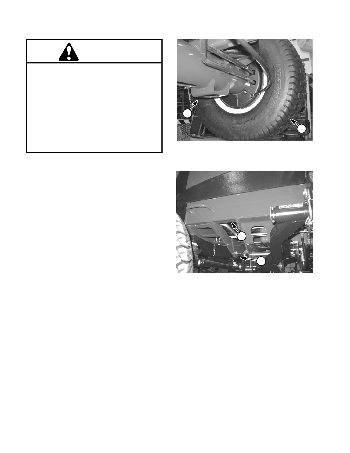
Front End Jacking (Fig. 1)
1. Apply parking brake and chock both rear tires to prevent the machine from moving.
2
1
Figure 1
1. Front wheel 2. Front jacking point
2. Position jack securely under the frame axle tube, just
to the inside of the front wheel.
3. Jack front of machine off the ground.
4. Position jack stands under the frame as close to the
wheel as possible to support the machine.
Rear End Jacking (Fig. 2)
1. Apply parking brake and chock both front tires to prevent the machine from moving.
2. Place jack securely at the center of the rear axle under the axle pivot bracket. Jack rear of machine off the
ground.
3. Position jack stands under the frame to support the
machine.
Safety and Instruction Decals
Numerous safety and instruction decals are affixed to
the traction unit and the cutting units of yourReelmaster.
If any decal becomes illegible or damaged, install a new
decal. Part numbers for decals are listed in your Part
Catalogs. Order replacement decals from your Authorized Toro Distributor.
2
1
Figure 2
1. Axle center 2. Jack stand location
Rev. B
Reelmaster 5010 SeriesPage 1 -- 4Safety
Page 9

Product Records and Maintenance
Table of Contents
Chapter 2
PRODUCT RECORDS 1.........................
MAINTENANCE 1...............................
EQUIVALENTS AND CONVERSIONS 2...........
Decimal and Millimeter Equivalents 2............
U.S. to Metric Conversions 2...................
TORQUE SPECIFICATIONS 3....................
Fastener Identification 3.......................
Using a Torque Wrench with an Offset Wrench 3..
Standard Torque for Dry, Zinc Plated and
Steel Fasteners (Inch Series) 4...............
Standard Torque for Dry, Zinc Plated and
Steel Fasteners (Metric Series) 5..............
Other Torque Specifications 6..................
Conversion Factors 6..........................
Product Records
Insert Operator’s Manuals and Parts Catalogs for your
Reelmaster at the end of this chapter. Additionally, if any
optional equipment or accessories have been installed
to your machine, insert the Installation Instructions, Operator’s Manuals and Parts Catalogs for those options
at the end of this chapter.
Product Records
and Maintenance
Maintenance
Maintenance procedures and recommended service intervals for your Reelmaster are covered in the Traction
Unit and Cutting Unit Operator’s Manuals. Refer to
those publications when performing regular equipment
maintenance.
Reelmaster 5010 Series Page 2 -- 1 Product Records and Maintenance
Rev. B
Page 10
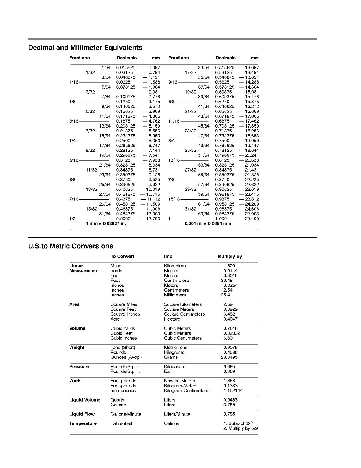
Equivalents and Conversions
0.09375
Reelmaster 5010 SeriesPage 2 -- 2Product Records and Maintenance
Page 11
Torque Specifications
Recommended fastener torque values are listed in the
following tables. For critical applications, as determined
by Toro, either the recommended torque or a torque that
is unique to the application is clearly identified and specified in this Service Manual.
These Torque Specifications for the installation and
tightening of fasteners s hall apply to all fasteners which
do not have a specific requirement identified in this Service Manual. The following factors shall be considered
when applying torque: cleanliness of the fastener, use
of a thread sealant (e.g. Loctite), degree of lubrication
on the fastener, presence of a prevailing torque feature
(e.g. Nylock nut), hardness of the surface underneath
the fastener’s head or similar condition which affects the
installation.
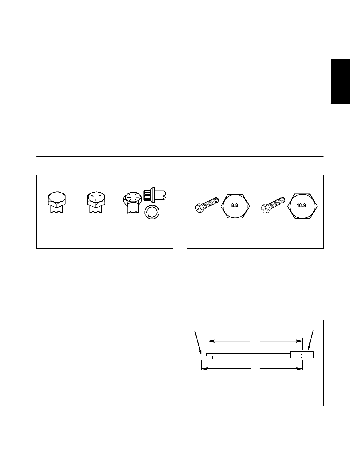
Fastener Identification
As noted in the following tables, torque values should be
reduced by 25% for lubricated fasteners to achieve
the s imilar stress as a dry fastener. Torque values may
also have to be reduced when the fastener is threaded
into aluminum or brass. The specific torque value
should be determined based on the aluminum or brass
material strength, fastener size, length of thread engagement, etc.
The standard method of verifying torque shall be performed by marking a line on the fastener (head or nut)
and mating part, then back off fastener 1/4 of a turn.
Measure the torque required to tighten the fastener until
the lines match up.
Product Records
and Maintenance
Grade 1 Grade 5 Grade 8
Inch Series Bolts and Screws
Figure 1
Using a Torque Wrench with an Offset Wrench
Use ofan offset wrench (e.g. crowfoot wrench) will affect
torque wrench calibration due to the effective change of
torque wrench length. When using a torque wrench with
an offset wrench, multiply the listed torque recommendation by the calculated torque conversion factor (Fig.
3) to determine proper tightening torque. Tightening
torque when using a torque wrench with an offset
wrench will be lower than the listed torque recommendation.
Example: The measured effective length of the torque
wrench (distance from the center of the handle to the
center of the square drive) is 18”.
The measured effective length of the torque wrench with
the offset wrench installed (distance from the center of
the handle to the center of the offset wrench) is 19”.
Class 8.8 Class 10.9
Metric Bolts and Screws
Figure 2
If the listed torque recommendation for a fastener is
from 76 to 94 ft--lb, the proper torque when using this
torque wrench with an offset wrench would be from 72
to 89 ft--lb.
(effective length of
torque wrench)
A
B
(effective length of torque
wrench + offset wrench)
TORQUE CONVERSION FACTOR = A/ B
Torque wrenchOffset wrench
The calculated torque conversion factor for this torque
wrench with this offset wrench would be 18 / 19 = 0.947.
Reelmaster 5010 Series Page 2 -- 3 Product Records and Maintenance
Rev. B
Figure 3
Page 12
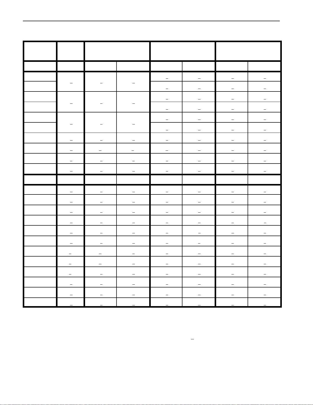
Standard Torque for Dry, Zinc Plated and Steel Fasteners (Inch Series)
Thread Size
# 6 -- 32 UNC
# 6 -- 40 UNF
# 8 -- 32 UNC
# 8 -- 36 UNF
#10--24UNC
#10--32UNF
1/4 -- 20 UNC 48 + 7 53 + 7 599 + 79 100 + 10 1130 + 113 140 + 15 1582 + 169
1/4 -- 28 UNF 53 + 7 65 + 10 734 + 11 3 11 5 + 12 1299 + 136 160 + 17 1808 + 192
5/16 -- 18 UNC 115 + 15 105 + 15 1186 + 169 200 + 25 2260 + 282 300 + 30 3390 + 339
5/16 -- 24 UNF 138 + 17 128 + 17 1446 + 192 225 + 25 2542 + 282 325 + 33 3672 + 373
3/8 -- 16 UNC 16 + 2 16 + 2 22 + 3 30 + 3 41 + 4 43 + 5 58 + 7
Grade 1, 5 &
8withThin
Height Nuts
in--lb in--lb N--cm in--lb N--cm in--lb N--cm
10 + 2 13 + 2 147 + 23
13 + 2 25 + 5 282 + 30
18 + 2 30 + 5 339 + 56
ft--lb ft--lb N--m ft--lb N--m ft--lb N--m
SAE Grade 1 Bolts, Screws, Studs &
Sems with Regular Height Nuts
(SAE J995 Grade 2 or Stronger Nuts)
SAE Grade 5 Bolts, Screws, Studs &
Sems with Regular Height Nuts
(SAE J995 Grade 2 or Stronger Nuts)
15 + 2 169 + 23 23 + 3 262 + 34
17 + 2 192 + 23 25 + 3 282 + 34
29 + 3 328 + 34 41 + 5 463 + 56
31 + 4 350 + 45 43 + 5 486 + 56
42 + 5 475 + 56 60 + 6 678 + 68
48 + 5 542 + 56 68 + 7 768 + 79
SAE Grade 8 Bolts, Screws, Studs &
Sems with Regular Height Nuts
(SAE J995 Grade 5 or Stronger Nuts)
3/8 -- 24 UNF 17 + 2 18 + 2 24 + 3 35 + 4 47 + 5 50 + 6 68 + 8
7/16 -- 14 UNC 27 + 3 27 + 3 37 + 4 50 + 5 68 + 7 70 + 7 95 + 9
7/16 -- 20 UNF 29 + 3 29 + 3 39 + 4 55 + 6 75 + 8 77 + 8 104 + 11
1/2 -- 13 UNC 30 + 3 48 + 7 65 + 9 75 + 8 102 + 11 105 + 11 142 + 15
1/2 -- 20 UNF 32 + 4 53 + 7 72 + 9 85 + 9 115 + 12 120 + 12 163 + 16
5/8 -- 11 UNC 65 + 10 88 + 12 119 + 16 150 + 15 203 + 20 210 + 21 285 + 28
5/8 -- 18 UNF 75 + 10 95 + 15 129 + 20 170 + 18 230 + 24 240 + 24 325 + 33
3/4 -- 10 UNC 93 + 12 140 + 20 190 + 27 265 + 27 359 + 37 375 + 38 508 + 52
3/4 -- 16 UNF 115 + 15 165 + 25 224 + 34 300 + 30 407 + 41 420 + 43 569 + 58
7/8 -- 9 UNC 140 + 20 225 + 25 305 + 34 430 + 45 583 + 61 600 + 60 813 + 81
7/8 -- 14 UNF 155 + 25 260 + 30 353 + 41 475 + 48 644 + 65 667 + 66 904 + 89
NOTE: Reduce torque values listed in the table above
by 25% for lubricated fasteners. Lubricated fasteners
are defined as threads coated with a lubricant such as
engine oil or thread sealant such as Loctite.
NOTE: The nominal torque values listed above for
Grade 5 and 8 fasteners are based on 75% of the minimum proof load specified in SAE J429. The tolerance is
approximately +
10% of the nominal torque value. Thin
height nuts include jam nuts.
NOTE: Torque values may have to be reduced when
installing fasteners into threaded aluminum or brass.
The specific torque value should be determined based
on the fastener size, the aluminum or base material
strength, length of thread engagement, etc.
Rev. B
Reelmaster 5010 SeriesPage 2 -- 4Product Records and Maintenance
Page 13
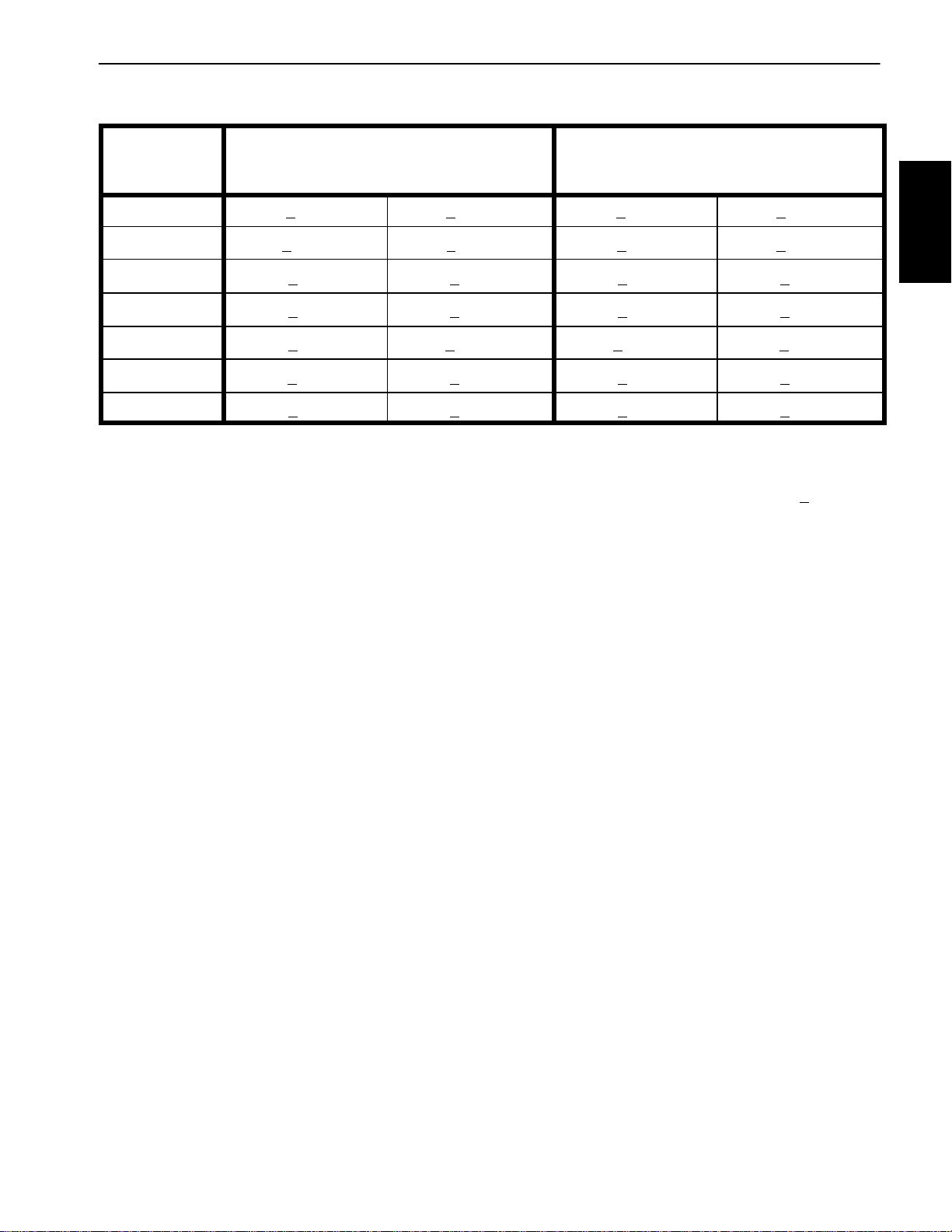
Standard Torque for Dry, Zinc Plated and Steel Fasteners (Metric Series)
Class 8.8 Bolts, Screws and Studs with
Thread Size Regular Height Nuts
(Class 8 or Stronger Nuts)
Class 10.9 Bolts, Screws and Studs with
Regular Height Nuts
(Class 10 or Stronger Nuts)
M5 X 0.8 57 + 6in--lb 644 + 68 N--cm 78 + 8in--lb 881 + 90 N--cm
M6 X 1.0 96 + 10 in--lb 1085 + 113 N - -c m 133 + 14 in--lb 1503 + 158 N--cm
M8 X 1.25 19 + 2ft--lb 26 + 3N--m 28 + 3ft--lb 38 + 4N--m
M10 X 1.5 38 + 4ft--lb 52 + 5N--m 54 + 6ft--lb 73 + 8N--m
M12 X 1.75 66 + 7ft--lb 90 + 10 N--m 93 + 10 ft--lb 126 + 14 N--m
M16 X 2.0 166 + 17 ft--lb 225 + 23 N--m 229 + 23 ft--lb 310 + 31 N--m
M20 X 2.5 325 + 33 ft--lb 440 + 45 N--m 450 + 46 ft--lb 610 + 62 N--m
NOTE: Reduce torque values listed in the table above
by 25% for lubricated fasteners. Lubricated fasteners
are defined as threads coated with a lubricant such as
engine oil or thread sealant such as Loctite.
NOTE: The nominal torque values listed above are
based on 75% of the minimum proof load specified in
SAE J1199. The tolerance is approximately+
nominal torque value.
NOTE: Torque values may have to be reduced when
installing fasteners into threaded aluminum or brass.
The specific torque value should be determined based
on the fastener size, the aluminum or base material
strength, length of thread engagement, etc.
10% ofthe
Product Records
and Maintenance
Reelmaster 5010 Series Page 2 -- 5 Product Records and Maintenance
Page 14
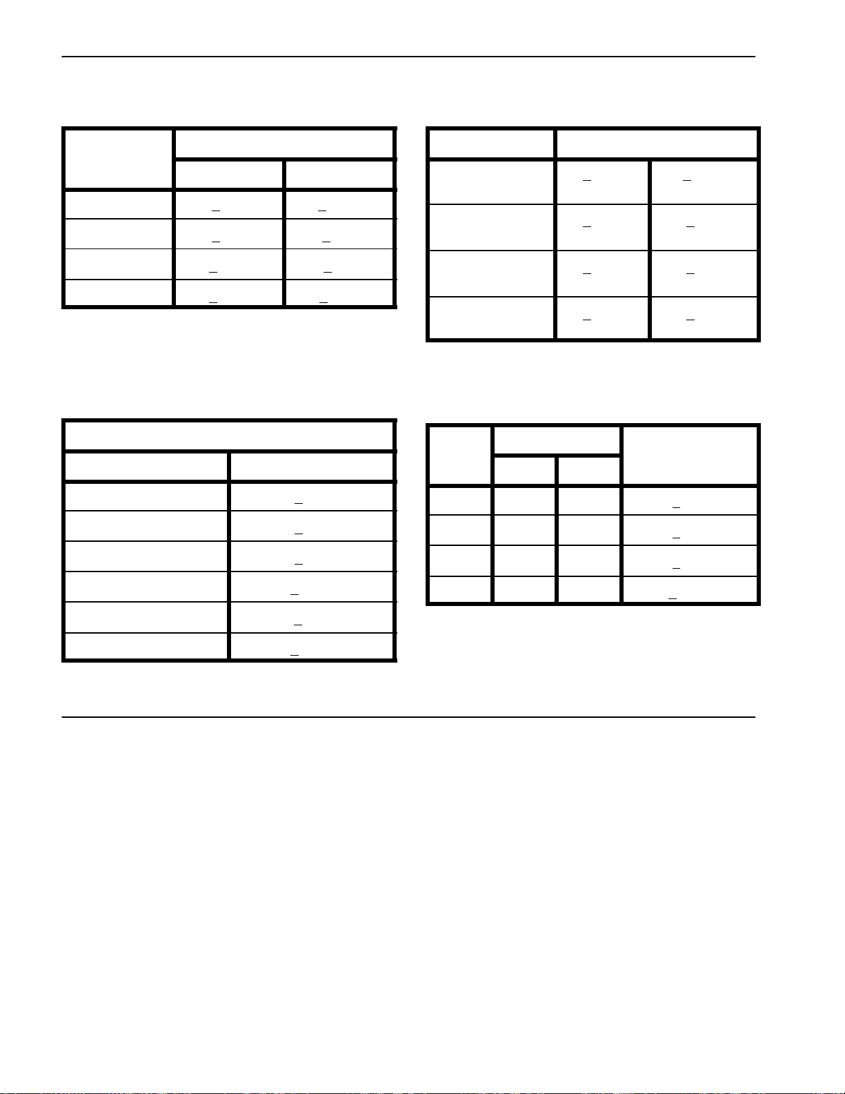
Other Torque Specifications
*
SAE Grade 8 Steel Set Screws
Recommended Torque
Thread Size
Square Head Hex Socket
1/4 -- 20 UNC 140 + 20 in--lb 73 + 12 in--lb
5/16 -- 18 UNC 215 + 35 in--lb 145 + 20 in--lb
3/8 -- 16 UNC 35 + 10 ft--lb 18 + 3ft--lb
1/2 -- 13 UNC 75 + 15 ft--lb 50 + 10 ft--lb
Thread Cutting Screws
(Zinc Plated Steel)
Type 1, Type 23 or Type F
Thread Size Baseline Torque*
No. 6 -- 32 UNC 20 + 5in--lb
Wheel Bolts and Lug Nuts
Thread Size
7/16 -- 20 UNF
Grade 5
1/2 -- 20 UNF
Grade 5
M12 X 1.25
Class 8.8
M12 X 1.5
Class 8.8
** For steel wheels and non--lubricated fasteners.
Thread Cutting Screws
(Zinc Plated Steel)
Thread
Size
No. 6 18 20 20 + 5in--lb
Threads per Inch
Type A Typ e B
Recommended Torque**
65 + 10 ft--lb 88 + 14 N--m
80 + 10 ft--lb 108 + 14 N--m
80 + 10 ft--lb 108 + 14 N--m
80 + 10 ft--lb 108 + 14 N--m
Baseline Torque
No. 8 -- 32 UNC 30 + 5in--lb
No. 10 -- 24 UNC 38 + 7in--lb
1/4 -- 20 UNC 85 + 15 in--lb
5/16 -- 18 UNC 110 + 20 in--lb
3/8 -- 16 UNC 200 + 100 in--lb
Conversion Factors
in--lb X 11.2985 = N--cm N--cm X 0.08851 = in--lb
ft--lb X 1.3558 = N--m N--m X 0.7376 = ft--lb
No. 8 15 18 30 + 5in--lb
No. 10 12 16 38 + 7in--lb
No. 12 11 14 85 + 15 in--lb
* Holesize, material strength, material thickness and finish must be considered when determining specific
torque values. All torque values are based on non--lubricated fasteners.
Reelmaster 5010 SeriesPage 2 -- 6Product Records and Maintenance
Page 15

Table of Contents
Chapter 3
Kubota Diesel Engine
GENERAL INFORMATION 1.....................
Traction Unit Operator’s Manual 1...............
Stopping the Engine (Reelmaster 5610) 1........
SPECIFICATIONS 2............................
Reelmaster 5210 2............................
Reelmaster 5410 and 5510 3...................
Reelmaster 5610 4............................
ADJUSTMENTS 5..............................
Adjust Throttle Control 5.......................
General Information
This Chapter gives information about specifications,
troubleshooting, testing and repair of the Kubota diesel
engine used in the Reelmaster 5010 Series of machines.
Most repairs and adjustments require tools which are
commonly available in many service shops. The use of
some specialized test equipment is explained in the engine service manual included at the end of this chapter.
However, the cost of the test equipment and the specialized nature of some repairs may dictate that the work be
done at an engine repair facility.
SERVICE AND REPAIRS 6......................
Fuel System 6................................
Air Cleaner 8.................................
Exhaust System 10...........................
Radiator 12..................................
Engine 14....................................
KUBOTA WORKSHOP MANUAL: 05 SERIES DIESEL
ENGINE
Service and repair parts for Kubota diesel engines are
supplied through your local Toro Distributor. If a parts list
is not available, be sure to provide your distributor with
the Toro model and serial number.
Engine
Kubota Diesel
Traction Unit Operator’s Manual
The T raction Unit Operator’s Manual provides information regarding the operation, general maintenance and
maintenance intervals for the Kubota diesel engine that
powers your Reelmaster machine. Refer to that publication for additional information when servicing the machine.
Stopping the Engine (Reelmaster 5610)
IMPORTANT: The engine used on the Reelmaster
5610 is turbo--charged. Before stopping the engine
after mowing or full load operation on Reelmaster
5610 machines, cool the turbo-charger by allowing
the engine to idle at low speed for 5 minutes.Failure
to do so may lead to turbo-charger trouble.
Reelmaster 5010 Series Page 3 -- 1 Kubota Diesel Engine
Page 16

Specifications: Reelmaster 5210
Item Description
Make / Designation Kubota D1105, 4-- stroke,
Number of Cylinders 3
Bore x Stroke 3.07” x 3.09” (78 mm x 78.4 mm)
Total Displacement 68.53 in3(1123 cc)
Compression Ratio 22.0:1
Firing Order 1 (fan end) -- 2 -- 3 (flywheel end)
Dry Weight (approximate) 205 lb. (93 kg)
Fuel No. 2--D Diesel Fuel (ASTM D975)
Fuel Injection Pump Bosch MD Type Mini
Fuel Injector Nozzle Mini Nozzle (DNOPD)
Fuel Tank Capacity 14 U.S. Gallons (53 Liters)
Governor Centrifugal Mechanical
Low Idle Speed (no load) 1200 to 1300 RPM
Liquid Cooled, OHV Diesel
High Idle Speed (no load) 3050 to 3250 RPM
Engine Oil API Classification CH--4, CI--4 or Higher
Oil Pump Gear Driven Trochoid Type
Crankcase Oil Capacity 4.0 U.S. Quarts (3.8 Liters) with Filter
Cooling System Capacity (including reserve tank) 5.5 U.S. Quarts (5.2 Liters)
Starter 12 VDC 1.4 KW
Alternator/Regulator 12 VDC 40 Amp
(see Traction Unit Operator’s Manual for viscosity recommendations)
Reelmaster 5010 SeriesPage 3 -- 2Kubota Diesel Engine
Page 17

Specifications: Reelmaster 5410 and 5510
Item Description
Make / Designation Kubota V1505, 4-- stroke,
Liquid Cooled, OHV Diesel
Number of Cylinders 4
Bore x Stroke 3.07” x 3.09” (78 mm x 78.4 mm)
Total Displacement 91.4 in3(1498 cc)
Compression Ratio 21.0:1
Firing Order 1 (fan end) -- 3 -- 4 (flywheel end) -- 2
Dry Weight (approximate) 242 lbs (110 kg)
Fuel No. 2--D Diesel Fuel (ASTM D975)
Fuel Injection Pump Bosch MD Type Mini
Fuel Injector Nozzle Mini Nozzle (DNOPD)
Fuel Tank Capacity 14 U.S. Gallons (53 Liters)
Governor Centrifugal Mechanical
Low Idle Speed (no load) 1200 to 1300 RPM
Engine
Kubota Diesel
High Idle Speed (no load) 3050 to 3250 RPM
Engine Oil API Classification CH--4, CI--4 or Higher
Oil Pump Gear Driven Trochoid Type
Crankcase Oil Capacity 6.3 U.S. Quarts (6 Liters) with Filter
Cooling System Capacity (including reserve tank) 7 U.S. Quarts (6.6 Liters)
Starter 12 VDC 1.4 KW
Alternator/Regulator 12 VDC 40 Amp
(see Traction Unit Operator’s Manual for viscosity recommendations)
Reelmaster 5010 Series Page 3 -- 3 Kubota Diesel Engine
Page 18

Specifications: Reelmaster 5610
Item Description
Make / Designation Kubota V1505, 4-- stroke,
Number of Cylinders 4
Bore x Stroke 3.07” x 3.09“ (78 mm x 78.4 mm)
Total Displacement 91.4 in3(1498 cc)
Compression Ratio 21.0:1
Firing Order 1 (fan end) -- 3 -- 4 (flywheel end) -- 2
Dry Weight (approximate) 251 lbs (114 kg)
Fuel No. 2--D Diesel Fuel (ASTM D975)
Fuel Injection Pump Bosch MD Type Mini
Fuel Injector Nozzle Mini Nozzle (DNOPD)
Fuel Tank Capacity 14 U.S. Gallons (53 Liters)
Governor Centrifugal Mechanical
Low Idle Speed (no load) 1200 to 1300 RPM
Liquid Cooled, OHV, Turbocharged Diesel
High Idle Speed (no load) 3050 to 3250 RPM
Engine Oil API Classification CH--4, CI--4 or Higher
Oil Pump Gear Driven Trochoid Type
Crankcase Oil Capacity 5 U.S. Quarts (4.7 Liters) with Filter
Cooling System Capacity (including reserve tank) 10 U.S. Quarts (9.5 Liters)
Starter 12 VDC 1.4 KW
Alternator/Regulator 12 VDC 40 Amp
(see Traction Unit Operator’s Manual for viscosity recommendations)
Reelmaster 5010 SeriesPage 3 -- 4Kubota Diesel Engine
Page 19
Adjustments
Adjust Throttle Control
Proper throttle operation is dependent upon proper adjustment of throttle control. Make sure throttle control is
operating properly.
NOTE: The throttle cable swivel should be positioned
in the lowest hole in the speed control lever .
1. Move throttle control lever on control console to
FAST position.
2. Check position of the engine speed control lever on
fuel injection pump. The speed control lever should be
contacting the high speed screw when the throttle control lever is in the FAST position.
3. If necessary, throttle control can be adjusted by loosening cable clamp screw and repositioning control cable
until speed control lever contacts high speed screw
when the throttle control lever is in the FAST position.
Tighten cable clamp screw after adjustment has been
completed.
5
1. Throttle cable
2. High speed screw
3. Speed control lever
1
4
Figure 1
2
4. Swivel
5. Cable clamp
Engine
3
Kubota Diesel
Reelmaster 5010 Series Page 3 -- 5 Kubota Diesel Engine
Page 20
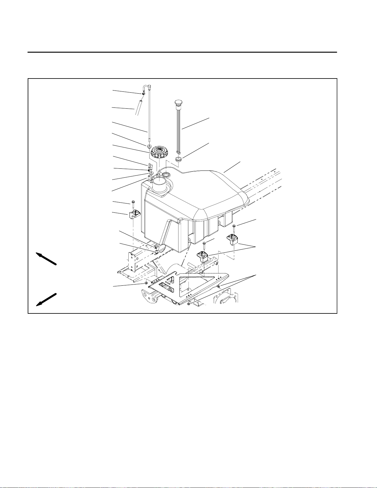
Service and Repairs
Fuel System
8
15
7
2
1
12
11
RIGHT
FRONT
1. Fuel cap
2. Bushing
3. Washer head screw (3 used)
4. Flange nut (3 used)
5. Clamp (3 used)
6. Return fitting
16
6
9
2
3
5
13
14
4
3
10
3
5
4
Figure 2
7. Suction fitting
8. Hose clamp
9. Hose clamp
10. Fuel tank
11. Grommet
12. Fuel gauge
13. Hose clamp
14. Draincock
15. Fuel hose
16. Return fuel hose
Reelmaster 5010 SeriesPage 3 -- 6Kubota Diesel Engine
Page 21
Fuel Tank Removal (Fig. 2)
DANGER
Because diesel fuel is highly flammable, use
caution when storing or handling it. Do not
smoke while filling the fuel tank. Do not fill fuel
tank while engine is running, when engine is hot
or when machine is in an enclosed area. Always
fill fuel tank outside and wipe up any spilled diesel fuel before starting the engine. Store fuel in a
clean, safety--approved container and keep container cap in place. Use diesel fuel for the engine
only; not for any other purpose.
Check Fuel Lines and Connections
Check fuel lines and connections periodically as recommended in the Traction Unit Operator’s Manual. Check
lines for deterioration, damage, leakage or loose connections. Replace fuel hoses, clamps and connections
as necessary.
Drain and Clean Fuel Tank
Drain and clean the fuel tank periodically as recommended in the Traction Unit Operator’s Manual. Also,
drain and clean the fuel tank if the fuel system becomes
contaminated or if the machine is to be stored for an extended period.
To clean fuel tank, flush tank out with clean diesel fuel.
Make sure tank is free of all contaminates and debris.
1. Park machine on a level surface, lower cutting units,
stop engine, engage parking brake and remove key
from the ignition switch.
2. Place drain pan under fuel tank. Make sure that drain
pan is large enough to hold fuel tank contents (see
Specifications in this chapter).
3. Open draincock on bottom of fuel tank and allow tank
to fully drain. Close draincock.
NOTE: Before removing fuel hoses from tank fittings,
label hoses for assembly purposes.
4. Loosen hose clamps and disconnect fuel hoses from
suction (item 7) and return (item 6) fittings on the top of
the fuel tank.
5. Remove fuel tank using Figure 2 as a guide.
Fuel Tank Installation (Fig. 2)
1. Install fuel tank to frame using Figure 2 as a guide.
2. Correctly connect fuel hoses to suction (item 7) and
return (item 6) fittings on the top of the fuel tank. Secure
fuel hoses with hose clamps.
3. Make sure that fuel tank draincock is closed. Fill fuel
tank.
Engine
Kubota Diesel
Reelmaster 5010 Series Page 3 -- 7 Kubota Diesel Engine
Page 22
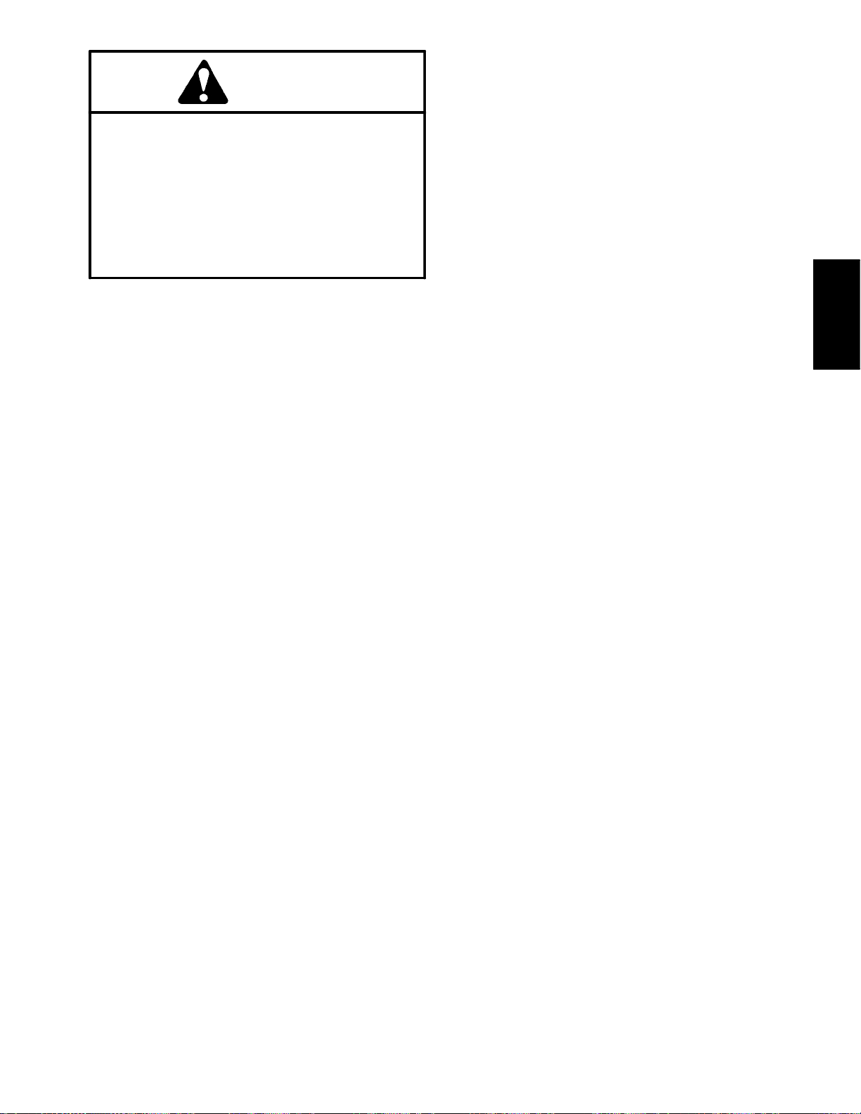
Air Cleaner
REELMASTER 5410--D/5510--D SHOWN
7
11
RIGHT
FRONT
16
11
2
3
4
6
5
THREAD
SEALANT
1
13
11
12
9
15
12
10
14
11
8
12
1. Air cleaner assembly
2. Hex nut
3. Bolt
4. Spring
5. Indicator
6. Adapter
7. Hose
8. Hose
9. Mount bracket
10. Air cleaner stand
11. Ho se cla mp
NOTE: The models in the Reelmaster 5010 Series
have a very similar air cleaner system. The air cleaner
removal and installation procedure is the same for all
models.
Figure 3
12. Flange nut
13. Cap screw (2 used)
14. Flange head screw (4 used)
15. Flange head screw (2 used)
16. Air cleaner mounting band
Reelmaster 5010 SeriesPage 3 -- 8Kubota Diesel Engine
Page 23
Removal (Fig. 3)
1. Park machine on a level surface, lower cutting units,
stop engine, engage parking brake and remove key
from the ignition switch. Raise hood.
2. Remove air cleaner components as needed using
Figures 3, 4 and 5 as guides.
3. See Traction Unit Operator’s Manual for air cleaner
service and maintenance procedures.
Installation (Fig. 3)
IMPORTANT: Any leaks in the air filter system will
allow dirt into engine and will cause serious engine
damage. Make sure that all air cleaner components
arein good condition and are properly secured during assembly.
1. Assemble air cleaner system using Figures 3, 4 and
5 as guides.
A. If indicator and adapter were removed from air
cleaner housing, apply thread sealant to adapter before installing adapter and indicator to housing.
B. Make sure that vacuator valve is pointed down after assembly.
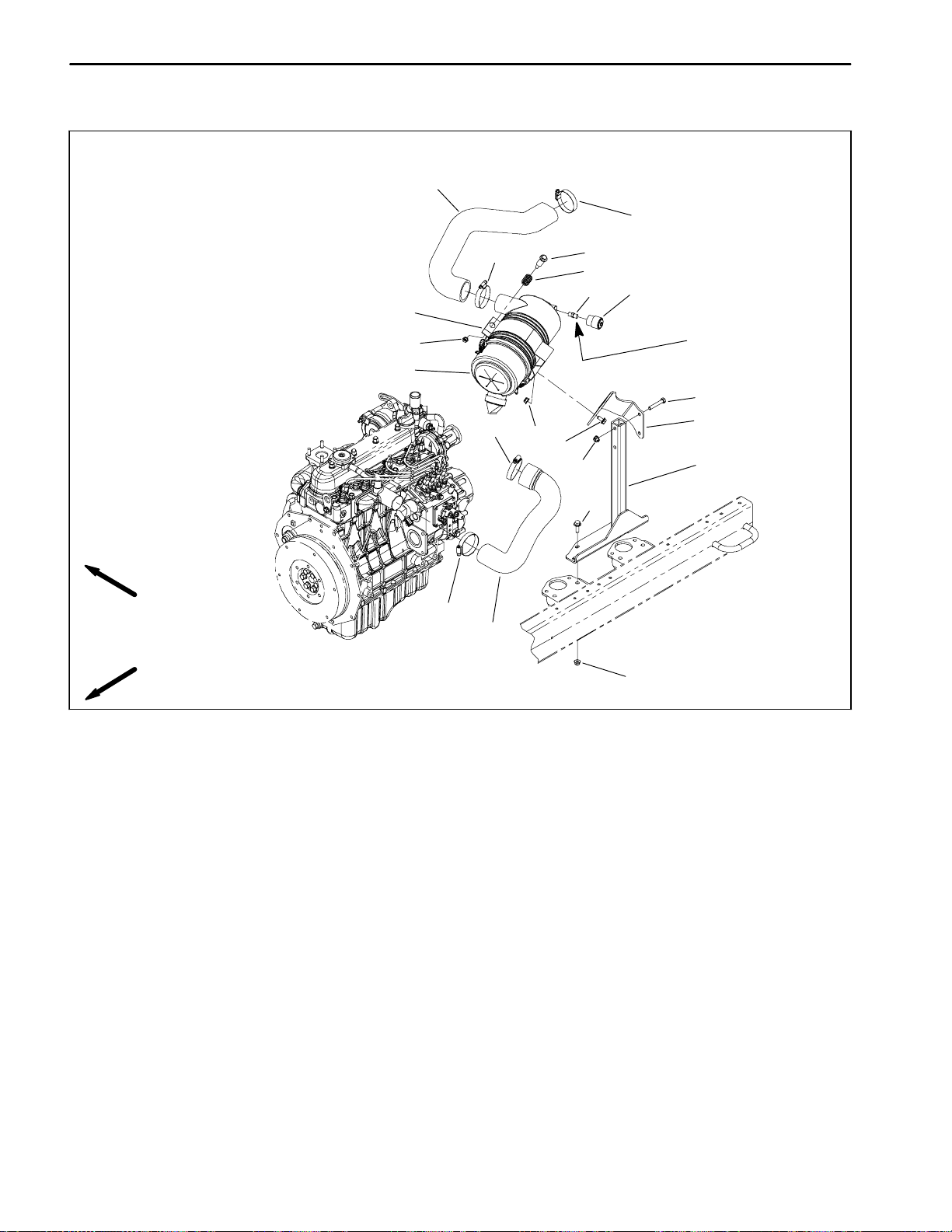
REELMASTER 5610--D
10
9
8
6
7
6
5
Figure 4
1. Air cleaner assembly
2. Mounting band
3. Adapter
4. Indicator
5. Hex nut
6. Hose clamp
7. Hose
11
8. Spacer
9. Hose
10. Hose
11. Ho se cla mp
12. Bolt
13. Spring
11
12
13
1
2
3
4
Engine
Kubota Diesel
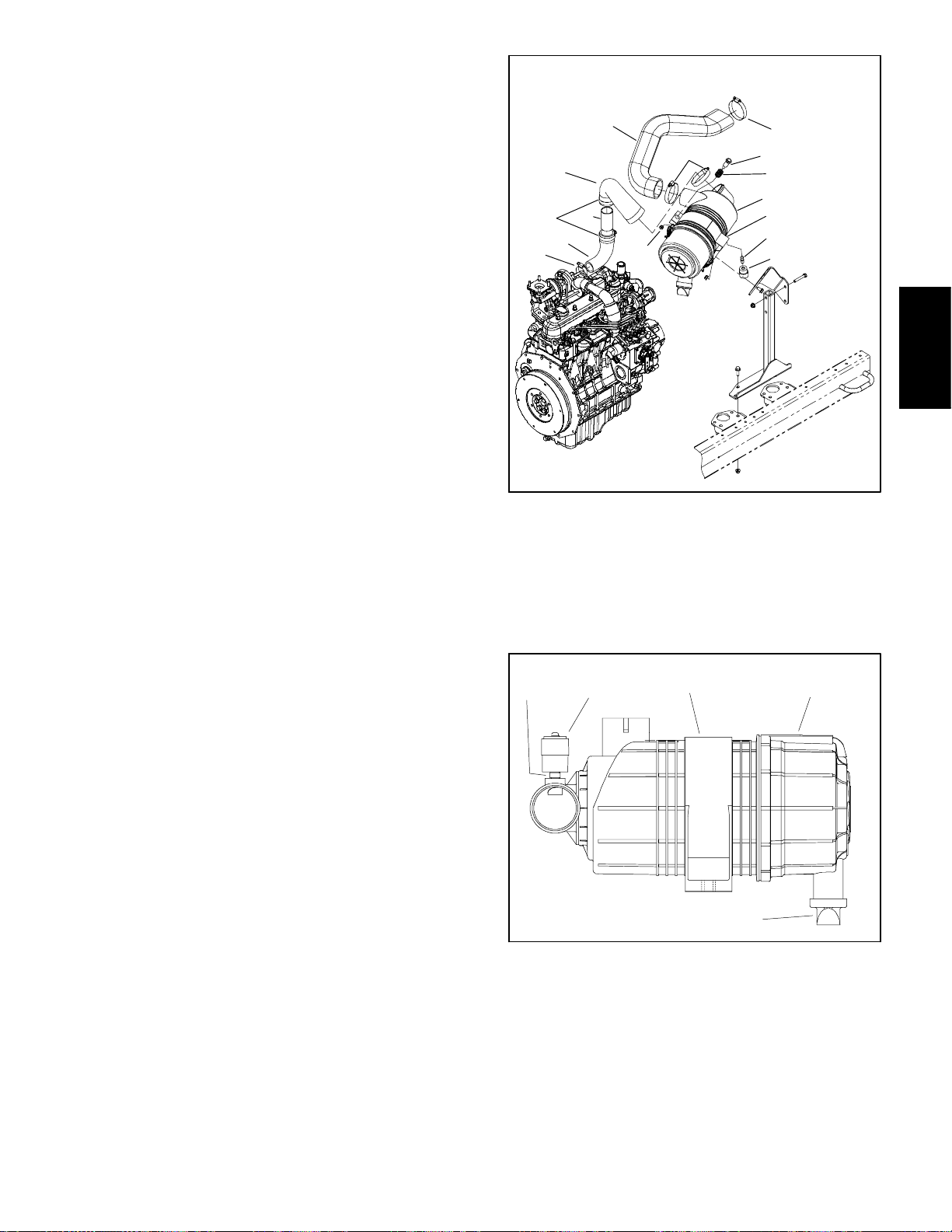
4
1. Mounting band
2. Cover
3. Vacuator valve
5
1
Figure 5
2
3
4. Adapter
5. Indicator
Reelmaster 5010 Series Page 3 -- 9 Kubota Diesel Engine
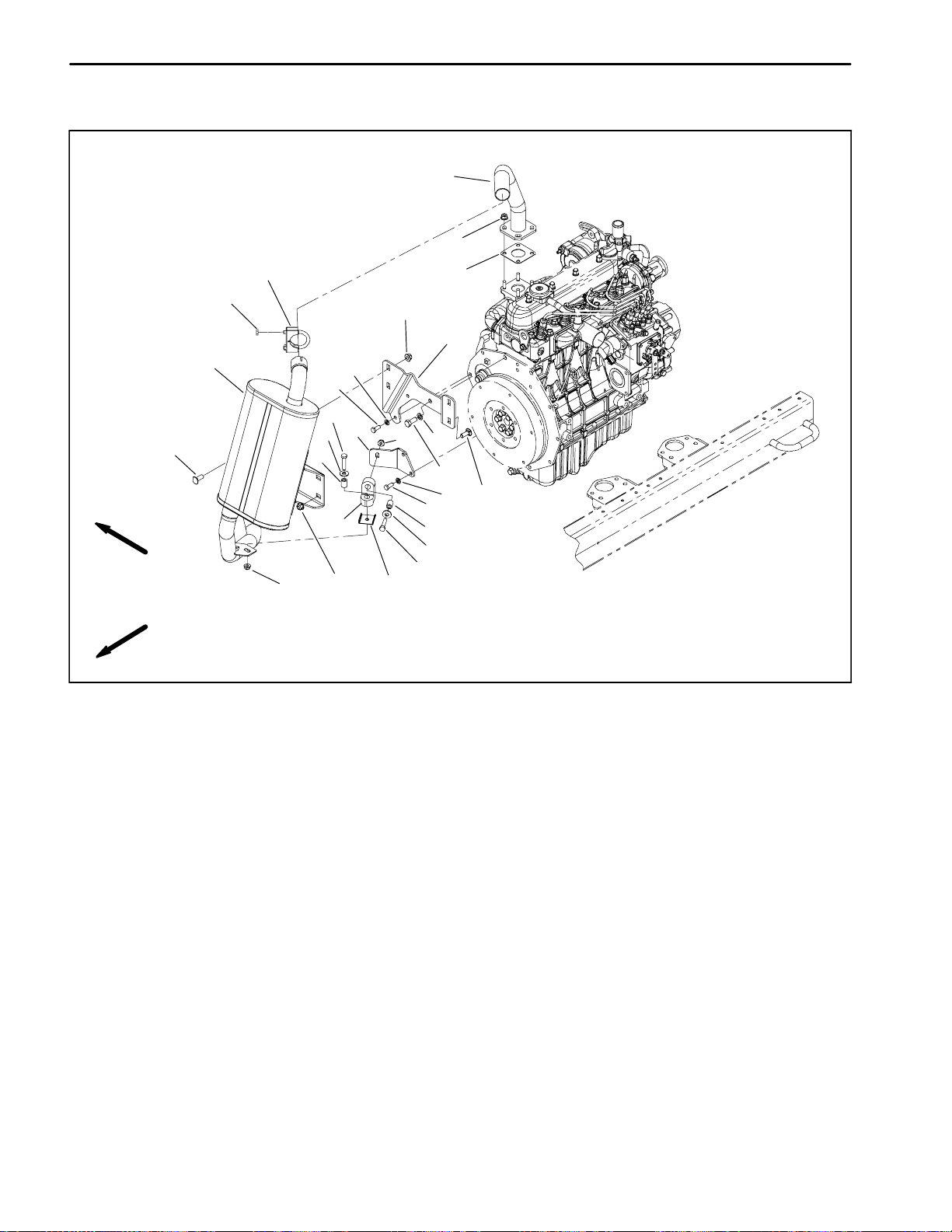
Page 24
Exhaust System
REELMASTER 5410--D/5510--D SHOWN
17
3
10
20
5
RIGHT
FRONT
1. Gasket
2. Lock washer (4 used)
3. Flange nut (4 used)
4. Cap screw (4 used)
5. Carriage screw (4 used)
6. Flange nut (4 used)
7. Lock washer
11
12
2
4
14
19
13
16
15
6
9
8. Cap screw
9. Isolator plate
10. Hex nut (2 used)
11. Cl amp
12. Flange nut (2 used)
13. Flat washer (2 used)
14. Cap screw (2 used)
6
12
7
8
4
16
13
14
Figure 6
2
1
18
5
15. Rubber hanger
16. Spacer (2 used)
17. Exhaust header
18. Support bracket
19. Tail pipe bracket
20. Muffler
NOTE: The models in the Reelmaster 5010 Series
have a very similar exhaust system. The exhaust system removal and installation procedure is the same for
all models.
Reelmaster 5010 SeriesPage 3 -- 10Kubota Diesel Engine
Page 25
Removal (Fig. 6)
Installation (Fig. 6)
1. Park machine on a level surface, lower cutting units,
stop engine, engage parking brake and remove key
from the ignition switch. Raise hood.
CAUTION
The muffler and exhaust pipe may be hot. To
avoid possible burns, allow the engine and exhaust system to cool before working on the exhaust system.
2. Remove exhaust system using Figure 6 as a guide.
NOTE: Make sure muffler flange and exhaust manifold
sealing surfaces are free of debris or damage that may
prevent a tight seal.
1. Place new muffler gasket on the exhaust manifold.
Install exhaust pipe to manifold and secure with four (4)
flange nuts.
IMPORTANT: Finger tighten all exhaust system fasteners before tightening so that there is no preload
on the exhaust system due to exhaust system assembly.
2. Install exhaust system to the engine using Figure 6
as a guide. Finger tighten all fasteners until all exhaust
system components have been installed. Then, fully
tighten fasteners to secure exhaust system.
Engine
Kubota Diesel
Reelmaster 5010 Series Page 3 -- 11 Kubota Diesel Engine
Page 26
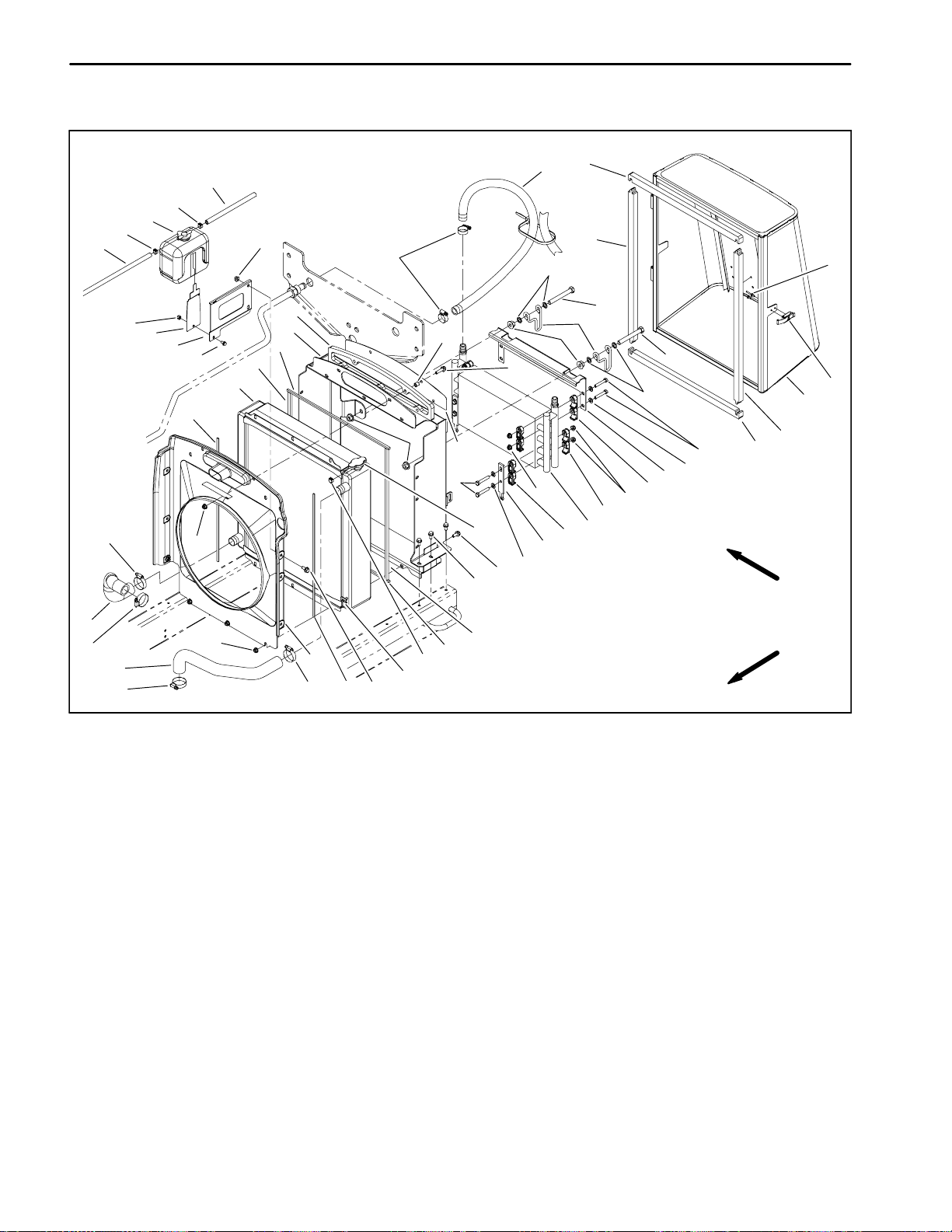
Radiator
2
3
11
28
38
2
1
20
4
29
13
10
34
23
24
33
8
21
5
16
13
26
16
13
25
16
1. Overflow bottle
2. Hose clamp (3 used)
3. Hose
4. Foam seal (2 used)
5. Foam seal (2 used)
6. Foam seal (2 used)
7. Oil cooler
8. Foam seal (2 used)
9. Flat washer (8 used)
10. Hose clamp (4 used)
11. Foam seal (2 used)
12. Flange nut (4 used)
13. Flange nut (22 used)
14. Oil cooler mount plate (2 used)
15. Oil cooler clamp (16 used)
6
22
40
12
27
5
16
30
16. Hose clamp (4 used)
17. Cap screw (4 used)
18. Clamp (2 used)
19. Cap screw (2 used)
20. Washer (4 used)
21. Radiator
22. Radiator frame
23. Reservoir bracket
24. Bracket
25. Hose
26. Hose
27. Fan shroud
28. Hose (2 used)
29. Rivet (2 used)
30. Flange head screw (9 used)
2
41
43
37
17
6
Figure 7
32
8
42
30
44
19
18
12
19
31
20
36
4
11
13
15
35
9
39
15
13
15
7
14
9
RIGHT
FRONT
31. Draw latch
32. Washer head screw (6 used)
33. Flange head screw
34. Lock nut
35. Cap screw (4 used)
36. Screen
37. Intake screen
38. Hose
39. Oil cooler bracket
40. Foam seal
41. Draincock
42. Radiator cap
43. Spacer (5 used)
44. Flange head screw (5 used)
NOTE: Three (3) radiators are used on Reelmaster
5010 series machines. Reelmaster 5410 and 5510 machines use the same radiator. Reelmaster 5210 and
5610 machines use different radiators. All models use
a similar procedure for radiator removal and installation.
Removal (Fig. 7)
1. Park machine on a level surface, lower cutting units,
stop engine, engage parking brake and remove key
from the ignition switch.
2. Raise the hood.
Reelmaster 5010 SeriesPage 3 -- 12Kubota Diesel Engine
Page 27
CAUTION
Do not open radiator cap or drain coolant if the
radiator or engine is hot. Pressurized, hot coolant can escape and cause burns.
Ethylene--glycol antifreeze is poisonous. Dispose of coolant properly, or store it in a properly
labeled container away from children and pets.
3. Drain coolant from radiator.
3. Secure fan shroud and radiator to radiator frame with
removed flange head screws and flange nuts. Make
sure that at least .250” (6.4 mm) clearance exists at all
points between shroud opening and fan.
4. Position coolant reservoir and brackets to the fan
shroud. Secure reservoir to fan shroud and radiator
frame with two (2) flange head screws and flange nuts.
5. Place spacers (item 43) into holes in foam seal (item
42). Position foam seal and air intake screen (item 37)
to radiator frame. Secure screen to machine with five (5)
flange head screws and flange nuts.
A. Slowly remove radiator cap from the radiator.
B. Place drain pan below the radiator draincock located on the bottom of the radiator. Make sure that
drain pan is large enough to hold cooling system contents (see Specifications in this Chapter).
C. Loosen draincock and allow coolant to drain from
radiator.
4. Remove screen from machine.
5. Disconnect radiator hoses (upper and lower) from
the radiator.
6. Loosen hose clamp and remove overflow hose from
radiator fill opening.
7. Remove two (2) flange head screws and flange nuts
that secure coolant reservoir and brackets to fan
shroud. Carefully position reservoir and brackets away
from the fan shroud.
8. Remove five (5) flange head screws and flange nuts
that secure air intake screen (item 37) to machine. Remove screen and foam seal (item 42). Locate and retrieve five (5) spacers (item 43).
6. Connect upper and lower radiator hoses to radiator
and secure with clamps.
7. Connect overflow hose to radiator fill opening and
secure with hose clamp.
8. Make sure radiator draincock is closed (threaded out
fully). Fill radiator with coolant.
9. Lower hood. Install screen to rear of machine.
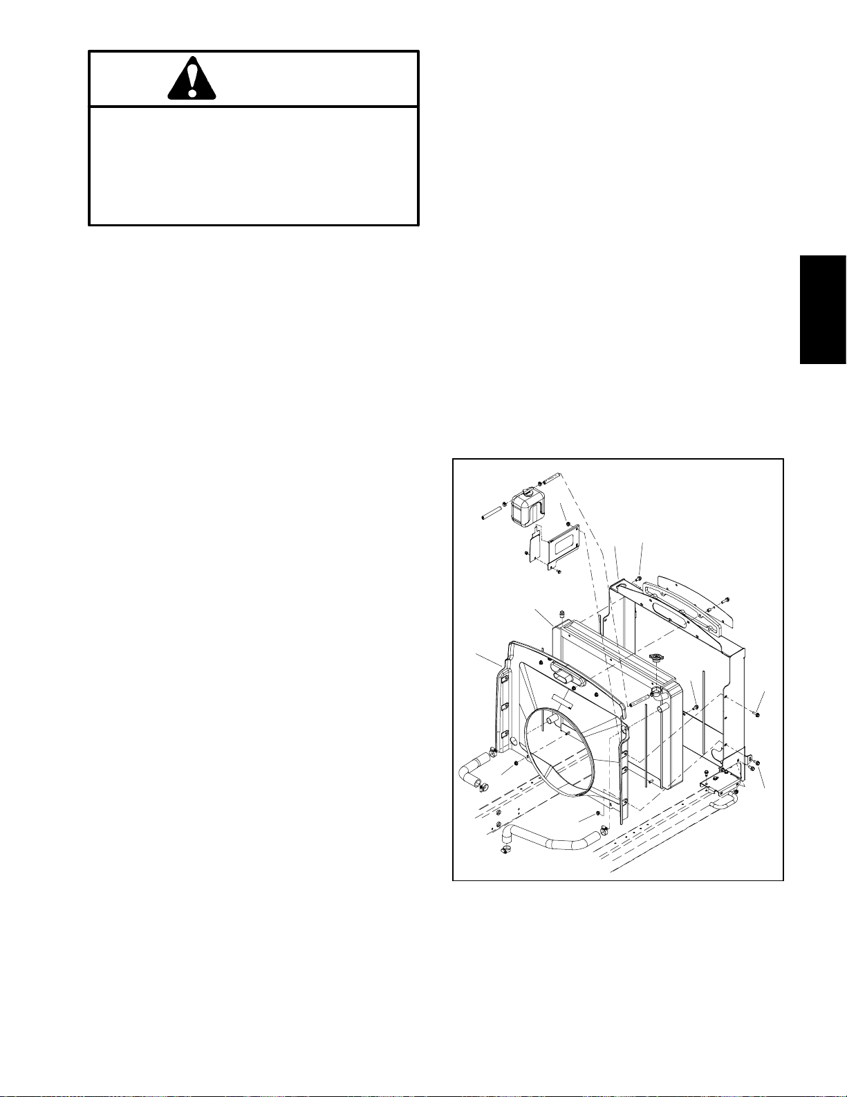
6
1
2
REELMASTER 5610
5
3
5
4
Engine
Kubota Diesel
9. Remove flange head screws and flange nuts that secure fan shroud and radiator to radiator frame. Position
fan shroud away from the radiator.
10.Carefully pull radiator assembly from the machine.
Plug radiator and hose openings to prevent contamination.
6
5
6
1 1.Inspect all foam seals placed between radiator, fan
shroud and radiator frame. Replace damaged foam
seals.
Installation (Fig. 7)
1. Remove plugs placed in radiator and hose openings
1. Radiator (RM 5610)
2. Fan shroud
3. Radiator frame
Figure 8
4. Flange head screw
5. Flange head screw
6. Flange nut
during the removal procedure.
2. Carefully position radiator assembly to the radiator
support. Position fan shroud to the radiator.
Reelmaster 5010 Series Page 3 -- 13 Kubota Diesel Engine
Page 28
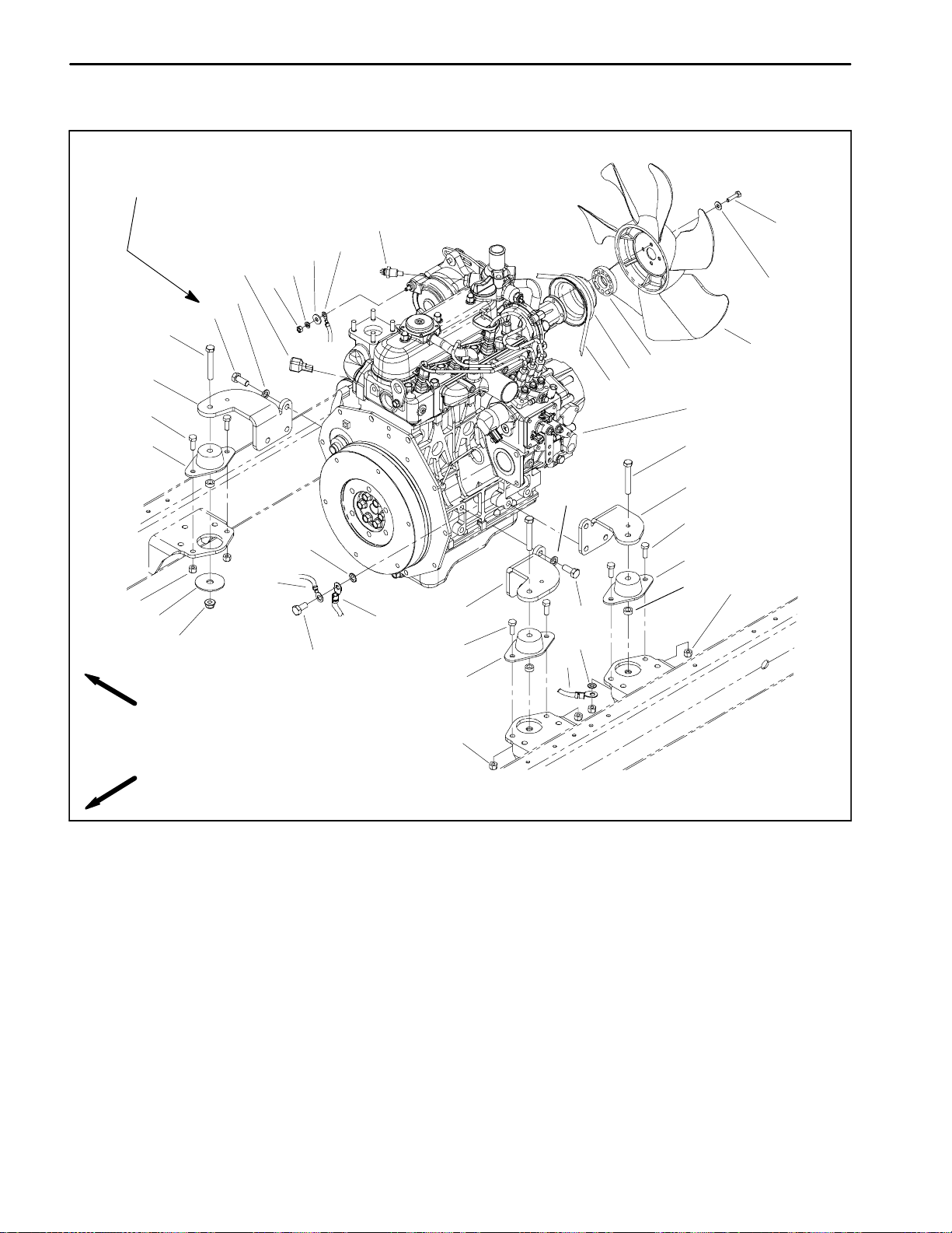
Engine
34 to 42 ft--lb
(47to56N--m)
3
26
11
18
24
25
19
20
16
2
7
17
23
14
10
15
5
4
1
7
23
25
5
13
26
9
6
27
8
21
23
5
2
12
27
4
22
9
4
RIGHT
FRONT
1. Engine assembly
2. Cap screw (12 used)
3. Temperature sender
4. Engine mount (4 used)
5. Cap screw (2 used per mount)
6. Snubbing washer (4 used)
7. Cap screw (4 used)
8. Flange nut (4 used)
9. Lock nut (2 used per mount)
10. Fan spacer
11. Cap screw (4 used)
12. Lock washer
13. Lock washer
14. Pulley
15. V --belt
16. Flat washer (4 used)
17. Cooling fan
18. Flat washer
NOTE: The engine removal and installation procedure
is similar for all models in the Reelmaster 5010 Series.
9
Figure 9
19. Spring washer
20. Hex nut
21. Cap screw
22. Spacer (4 used)
23. Engine bracket (4 used)
24. Diode assembly
25. Lock washer (12 used)
26. Engine wire harness
27. Negative battery cable
Reelmaster 5010 SeriesPage 3 -- 14Kubota Diesel Engine
Page 29
Removal (Fig. 9)
1. Park machine on a level surface, lower cutting units,
stop engine and remove key from the ignition switch.
Chock wheels to keep the machine from moving.
2. Open hood.
3. Disconnect negative (--) and then positive (+) battery
cables from the battery.
CAUTION
Do not open radiator cap or drain coolant if the
radiator or engine is hot. Pressurized, hot coolant can escape and cause burns.
Ethylene--glycol antifreeze is poisonous. Dispose of coolant properly, or store it in a properly
labeled container away from children and pets.
3
1. Throttle cable end
2. Swivel
2
Figure 10
3. Cable clamp
1
Engine
Kubota Diesel
4. Drain coolant from radiator (see Radiator Removal
in this section).
5. Remove air cleaner from machine (see Air Cleaner
Removal in this section).
6. Remove exhaust system from machine (see Exhaust System Removal in this section).
7. Remove throttle cable from injector pump (Fig. 10):
A. Remove cap screw that secures throttle cable
end to swivel in speed control lever.
B. Loosen throttle cable clamp and remove cable
from clamp. Slide throttle cable end from swivel.
C. Position throttle cable away from the engine.
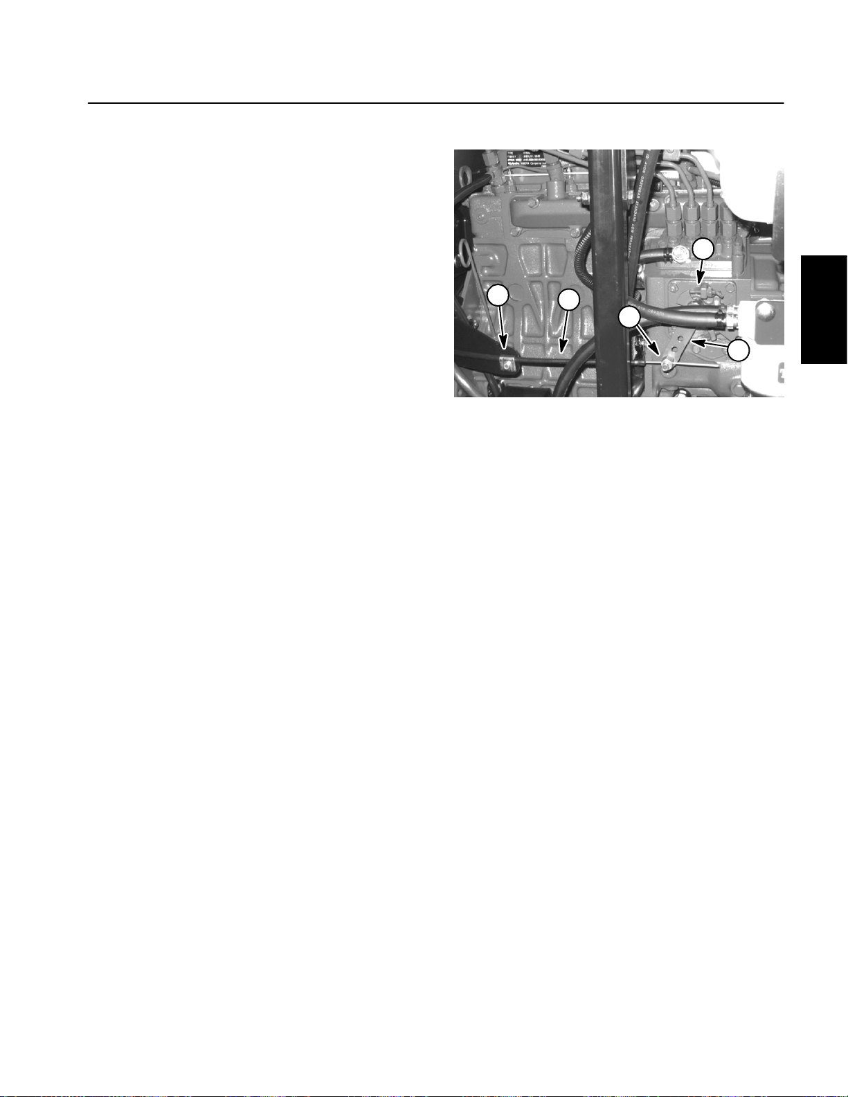
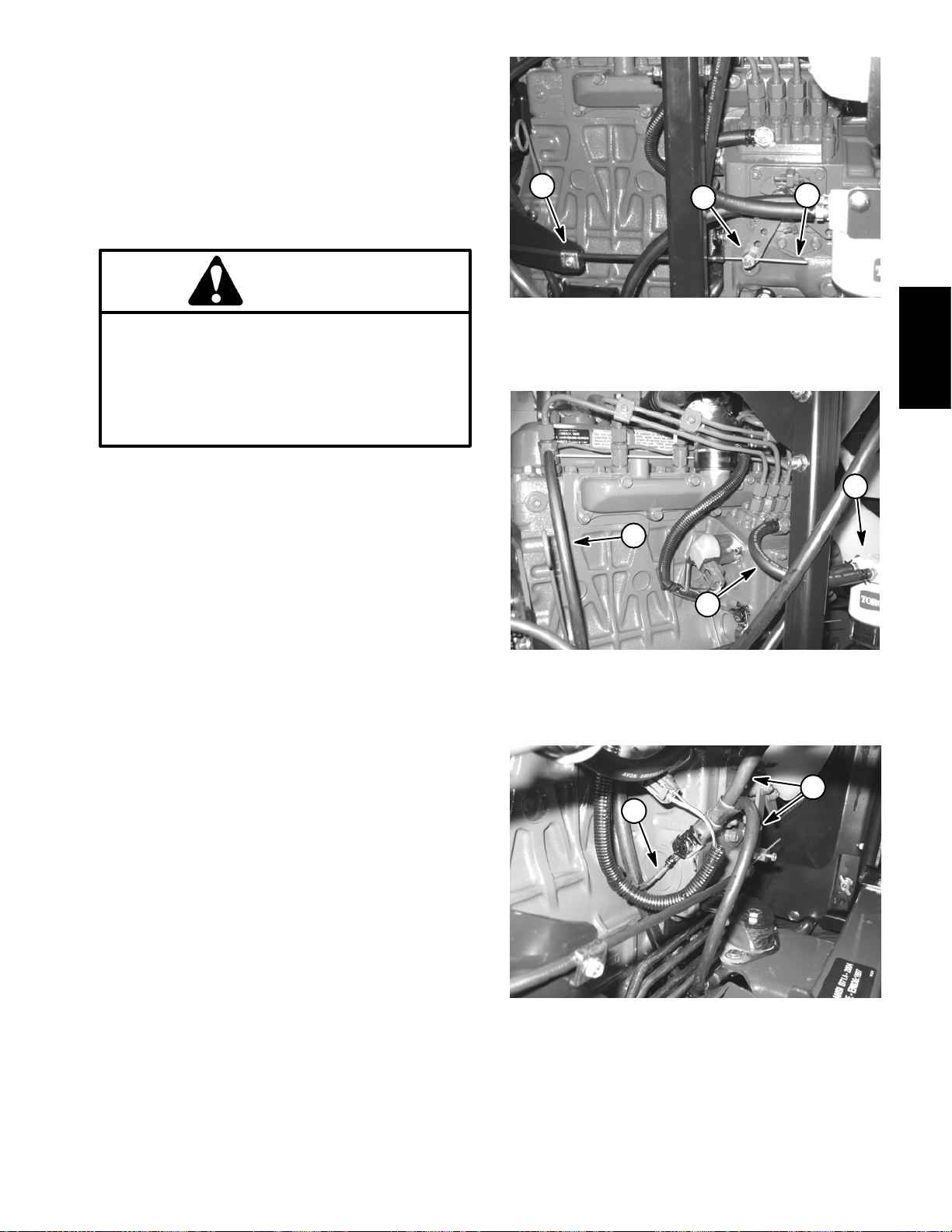
8. Disconnect hoses from engine:
A. Loosen clamps and remove upper and lower radiator hoses from the engine.
B. At injector pump, loosen hose clamp and disconnect supply fuel hose from the injector pump fitting
(Fig. 11).
1. Fuel return hose
2. Fuel supply hose
3
1
2
Figure 11
3. Fuel/water filter
1
2
C. Loosen hose clamp and disconnect fuel return
hose from front injector body (Fig. 11).
D. Plug disconnected hoses and engine openings to
prevent leakage and contamination. Position discon-
1. Negative battery cable 2. Harness ground
Figure 12
nected hoses away from engine.
Reelmaster 5010 Series Page 3 -- 15 Kubota Diesel Engine
Page 30
9. Disconnect hydraulic transmission drive shaft from
engine (see Hydraulic Transmission Drive Shaft Removal in the Service and Repairs section of Chapter 4
-- Hydraulic System). Support drive shaft away from engine.
Installation (Fig. 9)
1. Locate machine on a level surface with cutting units
lowered and key removed from the ignition switch.
Chock wheels to keep the machine from moving.
10.Disconnect wire harness connectors from the following engine components:
NOTE: Before disconnecting wire harness connectors,
label all electrical leads for assembly purposes.
A. Alternator connector and stud.
B. Oil pressure switch located near the engine oil filter.
C. Connector, fusible link connector and positive
battery cable from the starter motor.
D. High temperature shut down switch and temperature sender located on the water pump housing.
E. Fuel stop solenoid on injector pump.
F. Negative battery cable and harness ground from
injector pump (Fig. 12).
G. Glow plug strip.
1 1.Remove engine from machine:
2. Make sure that all parts removed from the engine
during maintenance or rebuilding are installed to the engine.
3. If engine brackets were removed from the engine,
secure brackets to engine with lock washers and cap
screws. Torque cap screws from 34 to 42 ft--lb (47 to
56 N--m).
4. Install engine to machine.
A. Attach short section of chain between lift tabs located on each end of the cylinder head
B. Connect a hoist or chain fall at the center of the
short section of chain. Apply enough tension on the
short chain so that the engine can be supported.
CAUTION
One person should operate lift or hoist while
another other person guides the engine into the
machine.
A. Attach short section of chain between lift tabs located on each end of the cylinder head.
B. Connect a hoist or chain fall at the center of the
short section of chain. Apply enough tension on the
short chain so that the engine will be supported.
C. Remove fasteners that secure the engine (with
brackets) to the engine mounts.
CAUTION
One person should operate lift or hoist while
another person guides the engine out of the machine.
IMPORTANT: Make sure to not damage the engine,
fuel hoses, hydraulic lines, electrical harness, radiator, batteryor other partswhile removing the engine.
D. Raise engine and remove toward front of machine.
IMPORTANT: Make sure to not damage the engine,
fuel hoses, hydraulic lines, electrical harness, radiator, batteryor other parts while installing the engine.
C. Lower engine to the machine frame. Make sure
fastener holes of the engine brackets are aligned
with the holes in the engine mounts.
D. Insert cap screw down through each engine
bracket and mount. Place spacer, snubbing washer
and then flange nut on four (4) cap screws. Tighten
fasteners to secure engine to engine mounts.
5. Connect hydraulic transmission drive shaft to engine
(see Hydraulic Transmission Drive Shaft Installation in
the Service and Repairs section of Chapter 4 -- Hydraulic System).
6. Connect all wire harness connectors to correct engine components.
12.If necessary, remove engine brackets from engine.
Reelmaster 5010 SeriesPage 3 -- 16Kubota Diesel Engine
Page 31

7. Remove plugs installed in hoses during disassembly. Connect hoses to the engine:
9. Install air cleaner (see Air Cleaner Installation in this
section).
A. Connect fuel supply and fuel return hoses to engine fittings (Fig. 11). Secure with hose clamps.
B. Connect upper and lower radiator hoses to the
engine. Secure with hose clamps.
8. Connect throttle cable to injector pump (Fig. 10):
A. Route throttle cable to injector pump on engine.
B. Install the throttle cable end into the swivel in
speed control lever. Secure cable end with cap
screw.
C. Position cable under cable clamp.
D. Adjust throttle control (see Adjust Throttle Control in the Adjustments section of this chapter).
10.Install exhaust system to machine (see Exhaust
System Installation in this section).
1 1.Add coolant to radiator.
12.Check engine oil level and adjust if needed.
13.Connect positive (+) and then negative (--) battery
cables to the battery .
14.Bleed fuel system.
15.Close hood.
Engine
Kubota Diesel
Reelmaster 5010 Series Page 3 -- 17 Kubota Diesel Engine
Page 32

This page is intentionally blank.
Reelmaster 5010 SeriesPage 3 -- 18Kubota Diesel Engine
Page 33

Table of Contents
Chapter 4
Hydraulic System
SPECIFICATIONS 2.............................
GENERAL INFORMATION 3.....................
Traction Unit Operator’s Manual 3...............
Check Hydraulic Fluid 3.......................
Towing Traction Unit 3.........................
Hydraulic Hoses 4............................
Hydraulic Fitting Installation 4...................
Relieving Hydraulic System Pressure 6..........
Traction Circuit Component Failure 6............
HYDRAULIC SCHEMATICS 7....................
HYDRAULIC FLOW DIAGRAMS 8................
Traction Circuit 8..............................
Mow Circuit 10...............................
Lift Circuit: Raise Cutting Units 12...............
Lift Circuit: Lower Cutting Units 14...............
Steering Circuit 16............................
SPECIAL TOOLS 18............................
TROUBLESHOOTING 22........................
General Hydraulic System Problems 22..........
Traction Circuit Problems 23....................
Mow Circuit Problems 24.......................
Lift Circuit Problems 25........................
Steering Circuit Problems 26...................
TESTING 28...................................
Traction Circuit Relief Valve (R3) and (R4)
Pressure Test 30............................
Traction Circuit Charge Pressure Test 32.........
Gear Pump (P3) Flow Test 34..................
Front Wheel Motor Efficiency Test 36............
Piston (Traction) Pump Flow Test 38.............
Relief Valve (R1) and (R2) Pressure Test 40......
Gear Pump (P1) and (P2) Flow Test 42..........
Reel Drive Motor Efficiency Test 44..............
Reel Drive Motor Cross--Over Relief Pressure
Test (Reelmaster 5510 and 5610) 46...........
Lift Relief Valve (R6) Pressure Test 48...........
Gear Pump (P4) Flow Test 50..................
Lift Cylinder Internal Leakage Test 52............
Steering Relief Valve (R10) Pressure Test 54.....
Steering Cylinder Internal Leakage Test 56.......
SERVICE AND REPAIRS 58.....................
General Precautions for Removing and Installing
Hydraulic System Components 58.............
Check Hydraulic Lines and Hoses 59............
Flush Hydraulic System 60.....................
Filtering Closed--Loop Traction Circuit 61.........
Hydraulic System Start--up 62..................
Hydraulic Reservoir 64........................
Hydraulic Pump Drive Shaft 66.................
Hydraulic Pump Assembly 68...................
Piston (Traction) Pump Service 72..............
Gear Pump Service 74.........................
Front Wheel Motor 76.........................
Motor
Wheel
Wheel Motor Service (Eaton) 81................
Mow Control Manifold 82.......................
Mow Control Manifold Service 84...............
Lift Control Manifold 88........................
Lift Control Manifold Service 90.................
CrossTrax
CrossTrax
Service 94..................................
Cutting Reel Motor 96.........................
Cutting Reel Motor Service 98..................
Lift Cylinder 102..............................
Lift Cylinder Service 104.......................
Steering Control Valve 106.....................
Steering Control Valve Service 108..............
Steering Cylinder 110..........................
Steering Cylinder Service 112..................
Oil Cooler 114................................
SAUER--DANFOSS LPV CLOSED CIRCUIT AXIAL
PISTON PUMPS REPAIR MANUAL
SAUER--DANFOSS LPV CLOSED CIRCUIT AXIAL
PISTON PUMPS SERVICE INSTRUCTIONS
PARKER TORQMOTOR
(TC, TB, TE, TJ, TF, TG, TH AND TL SERIES)
EATON DELTA MOTORS PARTS AND REPAIR
MANUAL
SAUER--DANFOSS STEERING UNIT TYPE OSPM
SERVICE MANUAL
Service (Parker) 80................
TM
AWD (Optional Kit) Manifold 92......
TM
AWD (Optional Kit) Manifold
TM
SERVICE PROCEDURE
System
Hydraulic
Reelmaster 5010 Series Hydraulic System (Rev. C)Page 4 -- 1
Page 34

Specifications
Item Description
Piston (Traction) Pump Sauer--Danfoss, LPV Closed Circuit Axial Piston Design
Maximum Pump Displacement (per revolution) 2.14 Cubic Inches (35 cc)
Gear Pump Casappa 4 section, positive displacement gear type pump
Section P1/P2 Displacement (per revolution) (RM 5210 &5410) 0.50 Cubic Inches (8.3 cc)
Section P1/P2 Displacement (per revolution) (RM 5510 &5610) 0.66 Cubic Inches (10.8cc)
Section P3 Displacement (per revolution) (all models) 0.37 Cubic Inches (6.1 cc)
Section P4 Displacement (per revolution) (all models) 0.24 Cubic Inches (3.9 cc)
Charge Circuit Relief (R5) Pressure 200 PSI (14 bar)
Traction Circuit Relief Pressure: Forward (R3) and Reverse (R4) 3625 PSI (250 bar)
Front Wheel Motors (see NOTE below)
Rear Wheel Motors (if equipped)
Mow Circuit Relief Pressure
Rear Mow Circuit (R1) 2500 PSI (172 bar)
Front Mow Circuit (R2) 3500PSI (241 bar)
Cutting Unit Motor (RM 5210 & RM 5410) Sauer--Danfoss gear motor
Displacement (per revolution) 0.73 Cubic Inches (12 cc)
Cutting Unit Motor (RM 5510 & RM 5610) Bosch gear motor
Displacement (per revolution) 1.18 Cubic Inches (19.3 cc)
Cross Over Relief Valve Pressure 1500 PSI (103 bar)
Steering Valve Sauer--Danfoss Steering Unit, Type OSPMS
Steering Circuit Relief (R10)Pressure 1000 PSI (69 bar)
Lift Circuit Relief (R6) Pressure 2000 PSI (138 bar)
Lift Circuit Lower Relief (R7) Pressure 500 PSI (34bar)
Hydraulic Filter (Transmission and Steering Circuits) Spin--on Cartridge Typewith 50 PSI (3.4 bar) Relief in Adapter
Parker orbital rotor motor, TG Series
Eaton geroler motor, Delta Series
Parker orbital rotor motor, TL Series
Hydraulic Filter (Mow and Lift Circuits) Spin--on CartridgeType with 50 PSI (3.4 bar) Reliefin Adapter
Hydraulic Oil See Traction Unit Operator’s Manual
Hydraulic Reservoir Capacity 11U.S. Gallons (41.6 L)
(filter adapter includes filter change indicator)
NOTE: Machines produced with serial number below
311000600 were produced with Parker brand front
wheel motors. Machines with serial number above
311000600wereproduced withEatonbrandfrontwheel
motors. If Parker brand wheel motors have been replaced, thereplacement wheel motors may have been
Eaton brand.
Reelmaster 5010 SeriesHydraulic System (Rev. C) Page 4 -- 2
Page 35

General Information
Traction Unit Operator’s Manual
The Traction Unit Operator’s Manual providesinformation regarding the operation,general maintenance and
maintenance intervals for your Reelmaster machine.
Referto that publication for additional informationwhen
servicing the machine.
Check Hydraulic Fluid
The hydraulic system on Reelmaster 5010 series machines is designed to operate on highquality hydraulic
fluid. The hydraulic system reservoir holds approximately11gallons (41.6 liters)of hydraulic fluid.Check lev-
elofhydraulic fluiddaily.SeeTractionUnitOperator’s
Manualfor fluid level checkingprocedure and hydraulic
oil recommendations.
System
1
Hydraulic
Towing Traction Unit
IMPORTANT: If towing limits are exceeded, severe
damage to the piston (traction) pump may occur.
Ifitbecomesnecessaryto tow or push themachine,tow
orpushataspeedbelow3mph(4.8 kph), and for a very
shortdistance.Ifthemachine needs to bemovedaconsiderabledistance,machineshouldbetransportedona
trailer.Thepiston(traction)pumpisequippedwith a bypassvalvethat needstobeloosened fortowingorpushing (Fig. 2). See Traction Unit Operator’s Manual for
Towing Procedures.
Figure 1
1. Hydraulic reservoir cap
2
1
Figure 2
1. Piston (traction) pump 2. Bypass valve
Reelmaster 5010 Series Hydraulic System (Rev. C)Page 4 -- 3
Page 36

Hydraulic Hoses
Hydraulichoses are subject to extreme conditions such
aspressuredifferentialsduringoperationandexposure
to weather, sun, chemicals, very warm storage conditionsormishandling duringoperationandmaintenance.
Theseconditions cancausedamageorprematuredeterioration. Some hoses are more susceptible to these
conditions than others.Inspectthe hoses frequentlyfor
signs of deterioration or damage.
WARNING
Before disconnecting or performing any work
on hydraulic system, relieve all pressure in
system. Stop engine; lower or support all cutting units.
When replacing a hydraulichose,be sure that thehose
is straight (not twisted) before tightening the fittings.
This can bedone by observingthe imprint onthe hose.
Use two wrenches; hold the hose straight with one
wrench and tighten the hose swivel nut onto the fitting
with the other wrench.
Hydraulic Fitting Installation
O--Ring Face Seal
1. Make sure both threads and sealing surfaces are
free of burrs, nicks, scratches or any foreign material.
2. Make sure the O--ring is installed and properly
seatedinthegroove.ItisrecommendedthattheO--ring
be replaced any time the connection is opened.
3. Lubricate the O--ring with a light coating of oil.
Keepbodyand handsawayfrom pinholeleaks
ornozzles that eject hydraulic fluid under high
pressure. Use paper orcardboard, not hands,
to search for leaks. Hydraulic fluid escaping
under pressure can have sufficient force to
penetrate the skin and cause serious injury. If
fluid is injected into the skin, it must be surgically removed within a few hours by a doctor
familiar with thistype of injury. Gangrenemay
result from such an injury.
Nut
Sleeve
Seal
Body
4. Put the tube and nut squarely into position on the
facesealendofthe fitting and tighten the nut until finger
tight.
5. Mark the nut and fitting body. Hold the body with a
wrench.Useanotherwrenchtotightenthe nuttothecorrect Flats FromFingerTight(F.F.F.T.). Themarkings on
thenutand fittingbodywillverifythattheconnectionhas
been tightened.
Size F.F.F.T.
4 (1/4 in. nominal hose or tubing) 0.75 +
6(3/8in.) 0.75+
8(1/2in.) 0.75+
10 (5/8 in.) 1.00 +
12 (3/4 in.) 0.75 +
16 (1 in.) 0.75 +
0.25
0.25
0.25
0.25
0.25
0.25
Figure 3
Final
Position
Mark Nut
and Body
Extend Line
Initial
Position
Finger Tight After ProperTightening
Figure 4
Reelmaster 5010 SeriesHydraulic System (Rev. C) Page 4 -- 4
Page 37

SAE Straight Thread O--Ring Port -- Non--adjustable
1. Make sure both threads and sealing surfaces are
free of burrs, nicks, scratches or any foreign material.
2. Always replace theO--ring sealwhen this typeoffitting shows signs of leakage.
3. Lubricate the O--ring with a light coating of oil.
O--Ring
4. Install thefitting into the port and tighten it down full
length until finger tight.
5. Tighten the fitting to the correct Flats From Finger
Tight (F.F.F.T.).
Size F.F.F.T.
4 (1/4 in. nominal hose or tubing) 1.00 +
6(3/8in.) 1.50+
8(1/2in.) 1.50+
10 (5/8 in.) 1.50 +
12 (3/4 in.) 1.50 +
16 (1 in.) 1.50 +
0.25
0.25
0.25
0.25
0.25
0.25
SAE Straight Thread O--Ring Port -- Adjustable
1. Make sure both threads and sealing surfaces are
free of burrs, nicks, scratches or any foreign material.
2. Always replace theO--ring sealwhen this typeoffitting shows signs of leakage.
3. Lubricate the O--ring with a light coating of oil.
4. Turn back the jamnut as faras possible. Makesure
the back up washerisnotloose and is pushedupasfar
as possible (Step 1).
Figure 5
Lock Nut
Back--up Washer
O--Ring
System
Hydraulic
5. Install the fitting into the port and tighten finger tight
until the washer contacts the face of the port (Step 2).
6. Toputthefittinginthedesired position, unscrew itby
the required amount, but no more than one full turn
(Step 3).
7. Hold thefitting in the desired positionwith awrench
and turn the jam nutwith anotherwrench to the correct
Flats From Finger Tight (F.F.F.T.) (Step 4).
Size F.F.F.T.
4 (1/4 in. nominal hose or tubing) 1.00 +
6(3/8in.) 1.50+
8(1/2in.) 1.50+
10 (5/8 in.) 1.50 +
12 (3/4 in.) 1.50 +
16 (1 in.) 1.50 +
0.25
0.25
0.25
0.25
0.25
0.25
Reelmaster 5010 Series Hydraulic System (Rev. C)Page 4 -- 5
Figure 6
Step 3Step 1
Step 2 Step 4
Figure 7
Page 38

Relieving Hydraulic System Pressure
Beforedisconnectingorperforming any work on the hydraulic system, all pressure in the hydraulic system
mustbe relieved.Parkmachineonalevelsurface,lower
cutting units fully, stop engine and engage parking
brake.
To relieve hydraulic pressure in traction circuit, move
tractionpedaltobothforwardandreverse directions. To
relieve hydraulic pressure in steering circuit, rotate
steering wheel in both directions.
Traction Circuit Component Failure
The traction circuit on Reelmaster 5010 series machines is a closed loop system that includes the piston
(traction) pump andtwo (2) wheel motors (4wheel motors on machines equipped with optional CrossTrax
AWD kit). If a component in the traction circuit should
fail,debrisandcontaminationfromthefailedcomponent
will circulate throughout the traction circuit. This contamination can damageothercomponents in thecircuit
so it mustberemoved to preventadditionalcomponent
failure.
If acomponent failure occurs in the traction circuit,it is
recommended that the entire traction circuit be disassembled,drainedandthoroughlycleanedtoensure that
all contamination is removed fromthe circuit.If any debrisremainsinthetractioncircuitandthe machine isoperated, the debris can cause additional component
failure.
TM
To relieve hydraulic pressure in lift circuit, start engine
and fully lower thecuttingunits. Turn key switch toOFF
and remove key from the ignition switch.
System pressure in cutting circuit is relieved when the
cutting units are disengaged.
Oncethefilter hasbeenplacedin thecircuit,operatethe
tractioncircuittoallow oilflowthroughthecircuit. Thefilter will remove contamination from the traction circuit
during circuit operation.The filter canbe removed from
the machine after contamination has been removed
from the traction circuit.
IMPORTANT: When operatingthetraction system with
the highpressure filter installed, make sure that flow is
always directed through the filter before entering a replaced component (e.g. do notpress the traction pedal
in the reverse direction if the filter is placed for forward
direction flow). If flow is reversed, debris from the filter
will re--enter the traction circuit.
NOTE: The traction pump case drain could allow tractioncircuitcontaminationtocontaminateotherhydraulic
circuits on the machine.
An alternative method of removing traction circuit contamination would be to temporarily install a high pressurehydraulicoilfilter(seeSpecialTools)intothecircuit.
Thefiltershouldbeusedwhenconnectinghydraulictest
gaugesinordertotesttractioncircuitcomponentsorafter replacing a failed traction circuit component (e.g.
traction(piston)pumporwheelmotor).Thefilterwillensure that contaminates are removed from the closed
loopandthus,donotcauseadditionalcomponentdamage.
Reelmaster 5010 SeriesHydraulic System (Rev. C) Page 4 -- 6
Page 39

Hydraulic Schematics
The hydraulic schematics for Reelmaster 5010 series
machines are located inChapter9 -- Foldout Drawings.
System
Hydraulic
Reelmaster 5010 Series Hydraulic System (Rev. C)Page 4 -- 7
Page 40

Hydraulic Flow Diagrams
IN
P
V1
R10
T
OUT
FRONT
C5 L
C1
C1 L
C4
C4 L
CV4
SV1
G4
SV2
SVRV
P4
CV1
C5
RIGHT
FRONT
C2/3
CV5
CV23
R7
T
SV3
C2/3 L
LIFT
CONTROL
MANIFOLD
LEFT
FRONT
CENTER
CONTROL
STEERING
L
R
VALVE
STEERING
CYLINDER
RIGHT
REAR
LEFT
REAR
Working Pressure
Traction Circuit (Forward Shown)
Reelmaster 5010 (5510/5610 Shown)
Low Pressure (Charge)
Return or Suction
Flow
RH
B
A
M7
M6
B
A
LH
G5
A
EXTERNAL CASE DRAIN
P3 P4
100 MESH
SUCTION
P2
P1
STRAINER
WHEEL
MOTORS
TRACTION
FORWARD
R3
B
R5 R4
REAR MOW CIRCUIT
G6
R9
G1
M3
C.U. 3
R11
M2
C.U. 2
OR1
R11
M1
BKLP1
MR1
OR4
CV
OR3
FC1
EP1
MSV2
MSV1
R1
P1
T
FRONT MOW CIRCUIT
BKLP2
MR2
FC2
EP2
R2
P2
M5
C.U. 5C.U. 1C.U. 4
R11
M1
R11R11
M4
M2
MOW
CONTROL
MANIFOLD
OR2
G2
P5
CASE
DRAIN
INTERNAL
R8
Figure 8
Reelmaster 5010 SeriesHydraulic System (Rev. C) Page 4 -- 8
Page 41

Traction Circuit
The hydraulic traction circuit consists of a variable displacementpistonpump(P5)connectedinaclosedloop,
parallelcircuittotwo(2)orbital rollervanewheelmotors.
The traction pumpinput shaft isrotated by a driveshaft
that is driven from the engine flywheel.
Traction circuit pressure (forward and reverse) can be
measured at test ports located in the hydraulic tubes
that connect the front wheel motors.
Forward Direction (Fig. 8)
Pushing the top ofthetraction pedal anglesthetraction
pump swash plate to create a flow of oil.This oil flow is
directed to the wheel motors via hydraulic hoses and
tubes to drive the wheels in the forward direction. Forward traction pressure is limited to 3625 PSI (250 bar)
by the forward traction relief valve (R3) located in the
traction pump.
Oilflowingfromthewheelmotorsreturnstothevariable
displacement pump and is continuously pumped
through the tractioncircuit as long as thetraction pedal
is pushed.
Theangleoftheswashplate determines pump flow and
ultimatelytractionspeed.Whenthetractionpedalisdepressedasmallamount,asmallswashplaterotationr esultsinlowpumpoutputandlowertractionspeed.When
the traction pedal is depressed fully, the pump swash
platerotatesfullytoprovidemaximumpumpoutputand
traction speed.
Gearpumpsection(P3)supplies oil flowforthesteering
circuitand also provides aconstantsupplyof charge oil
to the closed loop traction circuit. This charge oil provideslubrication fortractioncircuitcomponentsandalso
replenishes traction circuit oil thatis lost due to internal
leakage in the traction circuit.
Reverse Direction
The traction circuitoperates essentially the same inreverse as it does in the forward direction. However, the
flow through thecircuitis reversed. Pushingthe bottom
of the traction pedal rotates the traction pump swash
plate to create a flow of oil. This oil is directed to the
wheel motors to drive the wheels in the reverse direction. Reverse traction pressure is limited to 3625 PSI
(250bar)bythereversetractionreliefvalve(R4)located
in the traction pump.
Oil flowing from the wheelmotorsreturns to the traction
pump and is continuously pumped through the closed
loop traction circuit as long as the traction pedal is
pushed.
Thecharge circuit and flushingvalve(R10)function the
same in reverse as they do in the forward direction.
TM
CrossTrax
On machines equipped with the optional CrossTrax
AWD (Optional)
TM
AWD kit, four wheel motors are used (Fig. 9). Traction
pump flow is directed tothe front tiresand theopposite
rear tires to maximize traction. To reduce tire scuffing
when turning, traction system pressure is equalized in
theAWDmanifold withanorificeandabi--directionalrelief valve. Check valves in the AWD manifold allow the
rear wheel motors to over run during tightturns.
CrossTrax AWD Hydraulic Schematic
TM
G5
System
Hydraulic
Gearpump(P3)takesitssuction from the hydraulic reservoir.Charge pump flow is directed to the low pressure
side of the closedlooptractioncircuit. Charge pressure
is limited by the charge relief valve (R5) located in the
tractionpump.Thecharge relief pressureis200PSI(14
bar).
The piston pump (P5) includes a flushing valve (R10)
thatbleedsoffasmall amount of hydraulic fluid for coolingoftheclosedlooptractioncircuit.Thechargesystem
replenishesoilthatisbled from the traction circuitbythe
flushing valve.
Reelmaster 5010 Series Hydraulic System (Rev. C)Page 4 -- 9
Figure 9
Page 42

IN
P
L
V1
R10
T
OUT
CONTROL
STEERING
FRONT
CENTER
C1 L
C4
C4 L
CV4
SV1
G4
SV2
SVRV
P4
C5 L
C1
C5
RIGHT
FRONT
C2/3
CV5
CV1
CV23
R7
T
SV3
C2/3 L
LIFT
CONTROL
MANIFOLD
LEFT
FRONT
STEERING
CYLINDER
R
VALVE
Working Pressure
Low Pressure (Charge)
Return or Suction
Flow
RIGHT
REAR
Mow Circuit (Mow Shown)
Reelmaster 5010 (5510/5610 Shown)
LEFT
REAR
RH
B
A
M7
M6
B
A
LH
G5
A
EXTERNAL CASE DRAIN
P3 P4
100 MESH
SUCTION
P2
P1
STRAINER
WHEEL
MOTORS
TRACTION
FORWARD
R3
G6
B
R4
R5
REAR MOW CIRCUIT
R9
G1
M3
C.U. 3
R11
M2
C.U. 2
OR1
R11
M1
BKLP1
FC1
(ENERGIZED)
P1
EP1
OR3
R1
MR1
MSV1
OR4
CV
MSV2
T
MR2
EP2
R2
FRONT MOW CIRCUIT
BKLP2
FC2
(ENERGIZED)
P2
M5
C.U. 5C.U. 1C.U. 4
R11
M1
R11R11
M4
M2
MOW
CONTROL
MANIFOLD
OR2
G2
P5
CASE
DRAIN
INTERNAL
R8
Figure 10
Reelmaster 5010 SeriesHydraulic System (Rev. C) Page 4 -- 10
Page 43

Mow Circuit
A four sectiongear pump is coupled tothe piston(traction) pump. Gear pump sections (P1) and (P2) supply
hydraulic flow for the mow circuit. These gear pumps
take their suction from the hydraulic reservoir.
The mow control manifold contains two independent
control circuits for the frontand rear cutting units. Each
circuit is supplied by its own pump section. Pump section (P1) supplies hydraulic power to the rear cutting
unitsthroughmowcontrol manifold portP1,solenoidreliefvalve(MSV1)anddirectionvalve(MR1). Pump section (P2) supplies the front cutting units through
manifold port P2, solenoid relief valve (MSV2) and directionvalve(MR2).Both circuits share manifold port T,
which drains to theoilcooler,oilfilter and hydraulic reservoir.
On the mowcircuitsupplied by pumpsection(P1) (rear
cutting units), maximum system pressure is limited by
solenoid relief valve (R1),whichis set at2500PSI(172
bar).On the circuit supplied bypumpsection(P2)(front
cutting units), maximum system pressure is limited by
solenoid relief valve (R2),whichis set at3500PSI(241
bar).
OnReelmaster5510and5610machines,allcuttingreel
motorsareequippedwith cross overreliefvalvestopreventhydrauliccomponentdamage in caseacuttingreel
should stall.
The Electronic ControlModule (ECM) usesinputs from
various machine switches to determine when solenoid
relief valves (MSV1) and (MSV2) are to be energized.
The ECM also provides a slight delay in activation of
front and rear cutting units.
Whensolenoidrelief valves(MSV1)and(MSV2) arenot
energized (PTO switch in the OFF position), flow from
pump sections (P1) and (P2) is directed out the mow
manifold port T and returns to the hydraulic reservoir,
by--passing the reel motors.
P1 and is directed to reel speed control valve (FC1).
Flow throughthe speed control valve is pressure compensated by logic cartridge valve (EP1). Thelogic cartridge valve maintains a pressure of 75 PSI (5.2 bar)
across the speed control valve. Any excess flow is returnedto the hydraulic reservoir.Regulatedflow continuesthrough valve (MR1) and out totherearreelmotors
to rotate the cutting reels. When valve (MR1) is in the
Mowposition,therearreelsrotatecorrectlyformowing.
Returnoilfrom therearreelmotors isdirectedtothe reservoir through valve (MR1) and manifold port T.
Mow circuit pressure for the rear cutting units (pump
section P1) can be measured at manifold port G1.
When solenoid valve(MSV2)is energized bythe ECM,
oil flow from portP2is directed through reelspeedcontrolvalve(FC2).Flowthroughthespeedcontrolvalveis
pressure compensated by logic cartridge valve (EP2).
Thelogiccartridgevalvemaintainsapressure of 75 PSI
(5.2 bar) across the speed control valve. Any excess
flow is returned to the hydraulic reservoir. Regulated
flow continues throughvalve (MR2) andout to thefront
reel motors. When valve (MR2) is in the Mow position,
the front reels rotate correctly for mowing. Return oil
fromthefrontmotorsisdirectedtothereservoirthrough
valve (MR2) and manifold port T.
Mow circuit pressure for the front cutting units (pump
section P2) can be measured at manifold port G2.
Backlap
During the backlap mode of operation, the reel circuits
operate the same as in the Mow mode. When either
valve (MR1) or (MR2)is set to theBacklapposition, the
valvereversesthedirectionofhydraulicflowthroughthe
rearor front reel motors allowing thebacklapoperation.
System
Hydraulic
Mow (Fig. 10)
When solenoid valve(MSV1)is energized bythe ECM,
pumpsection(P1)flowenters mowcontrolmanifoldport
Reelmaster 5010 Series Hydraulic System (Rev. C)Page 4 -- 11
Page 44

TO REAR
MOW CIRCUIT
PUMP (P5)
INTERNAL
CASE
DRAIN
TO FRONT
MOW CIRCUIT
TO STEERING
& CHARGE
CIRCUIT
P4
P1
P2
100 MESH
SUCTION
STRAINER
P3 P4
T
LIFT
CONTROL
MANIFOLD
SVRV
G4
C2/3C2/3 L
RIGHT
FRONT
C4 L
C4
C1 L
C1
C5
C5 L
SV2
SV3
SV1
CV4
CV1
R7
CV5
CV23
FROM MOW
CONTROL
MANIFOLD
R8
LEFT
FRONT
LEFT
REAR
RIGHT
REAR
FRONT
CENTER
Figure 11
Reelmaster 5010
Lift Circuit: Raise Cutting Units
Working Pressure
Low Pressure (Charge)
Return or Suction
Flow
Reelmaster 5010 SeriesHydraulic System (Rev. C) Page 4 -- 12
Page 45

Lift Circuit: Raise Cutting Units
A four sectiongear pump is coupled tothe piston(traction) pump. Gear pump section (P4) supplies hydraulic
flow to the lift control manifold and ultimately for the lift
cylinders. The gearpump takes its suction from the hydraulic reservoir. Lift circuit pressure is limited to 2000
PSI (138 bar)by a solenoidrelief valve (SVRV)located
in the lift control manifold.
The lift control manifold includesfour(4) electrically operated solenoid valves. Valve (SVRV) is used to direct
gear pump flow to the lift cylinders when energized or
bypass pump flowback to the reservoirwhen de--energized.Valve(SV2)isusedto direct oil flow to retractthe
lift cylinders when energized or extend them when de-energized.Valve(SV1)allowshydraulicflowtothefront
lift cylinders when energized. Valve (SV3) allows hydraulic flow to the rear lift cylinders when energized.
Liftcircuitpressure can be monitored at lift controlmanifold port G4.
The Electronic ControlModule (ECM) usesinputs from
various machine switches to determine when lift manifold solenoid valves(SV1,SV2, SV3 andSVRV)are to
be energized. The ECM also provides a partial raise
position of the front outside cutting units.
Raise Cutting Units (Fig. 11)
When the joystick is moved to the raise position, solenoidvalve(SVRV)energizes alongwithsolenoidvalves
(SV1),(SV2)and(SV3).Theenergizedsolenoid valves
directgearpumpsectionP4oilflowtotherodendofthe
lift cylinders. Hydraulicpressure against therod side of
thecylinderscausestheshaftstoretract,andraisesthe
cutting units. Fixed orifices in the lift control manifold
(C1L, C4L, C5L and C23L) control the lifting speed by
providinga restriction for thereturnflowfromthe lift cylinders.
When the joystick is returned to the neutral (center)
position, the solenoidvalves arede--energized and the
lift cylinders (and cutting units) are held in the raised
position. Piloted check valvesin the lift controlmanifold
(CV1, CV4, CV5 and CV23) prevent the lift cylinders
(and cutting units) from dropping after they have been
raised.
System
Hydraulic
During conditions of not raising or lowering the cutting
units(joystickinthe neutral(center)position),allfour (4)
liftmanifoldsolenoid valves (SV1,SV2,SV3andSVRV)
are de--energized. Hydraulic flow from gear pump section(P4)by--passes theliftcylindersto theoilcoolerand
then to the hydraulic reservoir.
Reelmaster 5010 Series Hydraulic System (Rev. C)Page 4 -- 13
Page 46

TO REAR
MOW CIRCUIT
PUMP (P5)
INTERNAL
CASE
DRAIN
TO FRONT
MOW CIRCUIT
TO STEERING
& CHARGE
CIRCUIT
P4
P1
P2
100 MESH
SUCTION
STRAINER
P3 P4
T
LIFT
CONTROL
MANIFOLD
SVRV
G4
C2/3
RIGHT
FRONT
C4 L
C4
C1 L
C1
C5
C5 L
SV2
SV1
CV4
CV1
R7
CV5
SV3
CV23
C2/3 L
FROM MOW
CONTROL
MANIFOLD
R8
LEFT
FRONT
LEFT
REAR
RIGHT
REAR
FRONT
CENTER
Figure 12
Reelmaster 5010
Lift Circuit: Lower Cutting Units
Working Pressure
Low Pressure (Charge)
Return or Suction
Flow
Reelmaster 5010 SeriesHydraulic System (Rev. C) Page 4 -- 14
Page 47

Lift Circuit: Lower Cutting Units
A four sectiongear pump is coupled tothe piston(traction) pump. Gear pump section (P4) supplies hydraulic
flow to the lift control manifold and ultimately for the lift
cylinders. The gearpump takes its suction from the hydraulic reservoir. Lift circuit pressure is limited to 2000
PSI (138 bar)by a solenoidrelief valve (SVRV)located
in the lift control manifold.
The lift control manifold includesfour(4) electrically operated solenoid valves. Valve (SVRV) is used to direct
gear pump flow to the lift cylinders when energized or
bypass pump flowback to the reservoirwhen de--energized.Valve(SV2)isusedto direct oil flow to retractthe
lift cylinders when energized or extend them when de-energized.Valve(SV1)allowshydraulicflowtothefront
lift cylinders when energized. Valve (SV3) allows hydraulic flow to the rear lift cylinders when energized.
Liftcircuitpressure can be monitored at lift controlmanifold port G4.
The Electronic ControlModule (ECM) usesinputs from
various machine switches to determine when lift manifold solenoid valves(SV1,SV2, SV3 andSVRV)are to
be energized. The ECM also provides a partial raise
position of the front outside cutting units.
During conditions of not raising or lowering the cutting
units(joystickinthe neutral(center)position),allfour (4)
liftmanifoldsolenoid valves (SV1,SV2,SV3andSVRV)
are de--energized. Hydraulic flow from gear pump section(P4)by--passes theliftcylindersto theoilcoolerand
then to the hydraulic reservoir.
Lower Cutting Units (Fig. 12)
When the joystick is moved to the lower position, solenoidvalve(SVRV)energizes alongwithsolenoidvalves
(SV1)and (SV3). Solenoid valve (SV2) isin itsnormally
de-energized position,and directs oil flow to the piston
end of the lift cylinders. Hydraulic pressure against the
piston side of the cylinder causes the shafts to extend,
and lower the cutting units. The piloted check valvesin
the lift controlmanifold (CV1, CV4,CV5 and CV23)are
shifted by hydraulic pressure to allow return flow from
the extending lift cylinders. Fixed orifices in the liftcontrol manifold (C1,C4, C5 andC23) control the lowering
speed by providing a restriction for the return flowfrom
the lift cylinders.
Because cutting unit weight assists in extending the lift
cylinderswhenloweringthecuttingunits,lesshydraulic
pressure is necessary during the cutting unit lowering
operation.Liftcircuit lowerreliefvalve(R7)allows lift circuitpressureto be limited to 500 PSI (34 bar)whilelowering the cutting units.
NOTE: Adjustment of lift circuit lower relief valve (R7)
is not recommended.
When the joystick is returned to the neutral (center)
position, the solenoidvalves arede--energized and the
lift cylinders (and cutting units) are held in the lowered
position.
System
Hydraulic
Reelmaster 5010 Series Hydraulic System (Rev. C)Page 4 -- 15
Page 48

PISTON
MOVEMENT
Working Pressure
Low Pressure (Charge)
Return or Suction
Flow
LEFT TURN
FROM PUMP (P3)
TO TRACTION
R10
Steering Circuit
Reelmaster 5010
CYLINDER
STEERING
CHARGE CIRCUIT
VALVE
CONTROL
STEERING
PISTON
MOVEMENT
RIGHT TURN
FROM PUMP (P3)
TO TRACTION
R10
CYLINDER
STEERING
VALVE
CONTROL
CHARGE CIRCUIT
STEERING
Figure 13
Reelmaster 5010 SeriesHydraulic System (Rev. C) Page 4 -- 16
Page 49

Steering Circuit
A four sectiongear pump is coupled tothe piston(traction) pump. Gear pump section P3 supplies hydraulic
flow to the steering control valve and for the traction
chargecircuit. The gear pump takes its suction fromthe
hydraulicreservoir.Steeringcircuitpressureislimitedto
1000 PSI (69 bar)by a relief valve (R10) located in the
steering control.
With the steering wheel in the neutral position and the
enginerunning, flow enters the steering controlvalveat
the P port and goes through the steering control spool
valve, by--passing the rotary meter (V1) and steering
cylinder.Flowleavesthe controlvalvethroughtheTport
to the transmission oil filter and traction charge circuit.
Left Turn (Fig. 13)
When a left turn is made with the engine running, the
turningof the steering wheel positions thesteeringcontrol spool valve so that flow is directed through the bottomofthespool.Flowenteringthesteeringcontrolvalve
atthePportgoes through the spool and is routed to two
places. First, most of the flow through the valve is by-passed out the T port back to the transmission oil filter
andtractionchargecircuit.Second,theremainderofthe
flow is drawn through the rotary meter(V1) andout the
L port. Pressure contracts the steering cylinder piston
for a leftturn. The rotary meter ensuresthat the oil flow
to the steering cylinderis proportionalto theamount of
turningon the steering wheel. Fluidleaving thesteering
cylinder flows back through the steering control spool
valve and thenout of thesteeringcontrol valve through
the T port.
Thesteeringcontrolvalvereturnstotheneutral position
when turning is completed.
Right Turn (Fig. 13)
When a right turn is made with the engine running,the
turningof the steering wheel positions thesteeringcontrol spool valve so that flow is directed through the top
of the spool. Flow enteringthe steering control valve at
the P port goes through the spool and is routed to two
places. As in a left turn, most of the flow through the
valve is by--passed outthe T port back to the transmission oil filter and traction charge circuit. Also like a left
turn, the remainder of the flow is drawn through rotary
meter (V1) but goes out port R. Pressure extends the
steeringcylinderpistonforaright turn.The rotary meter
ensures that the oil flow to the steering cylinder is proportional to the amount of the turning on the steering
wheel. Fluid leaving the steering cylinder flows back
through the steering control spool valve then through
the T port and to the hydraulic reservoir.
Thesteeringcontrolvalvereturnstotheneutral position
when turning is completed.
System
Hydraulic
Reelmaster 5010 Series Hydraulic System (Rev. C)Page 4 -- 17
Page 50

Special Tools
Order these special tools from your Toro Distributor.
Hydraulic Pressure Test Kit
Toro Part Number: TOR47009
Use to take various pressure readings for diagnostic
tests. Quickdisconnect fittings provided attach directly
to mating fittings on machine test ports without tools. A
high pressure hose is provided for remote readings.
Contains one each: 1000 PSI (70 Bar), 5000 PSI (350
Bar) and 10000 PSI (700 Bar) gauges.Use gauges as
recommended in Testing section of this chapter.
Hydraulic Tester (Pressure and Flow)
Figure 14
Toro Part Number: TOR214678
Use to test hydraulic circuits and components for flow
andpressurecapacities asrecommendedinthe Testing
sectionofthischapter.Thistesterincludesthefollowing:
1. INLET H OSE: Hose connected fromthe system circuit to the inlet side of the hydraulic tester.
2. LOAD VALVE: A simulated working load is created
in the circuit by turning the valve to restrict flow.
3. PRESSURE GAUGE: Glycerinefilled 0 to5000 PSI
gauge to provide operating circuit pressure.
4. FLOW METER: Thismetermeasures actual oilflow
in the operating circuit with a gauge rated from 1 to 15
GPM(5to55LPM).
5. OUTLET HOSE: A hose from the outlet side of the
hydraulictesterconnects tothehydraulicsystem circuit.
6. FITTINGS:Anassortmentofhydraulic fittings areincluded with this kit.
Figure 15
Reelmaster 5010 SeriesHydraulic System (Rev. C) Page 4 -- 18
Page 51

40 GPM Hydraulic Tester (Pressure and Flow)
Toro Part Number: AT40002
Use to test hydraulic circuits and components for flow
andpressurecapacities asrecommendedinthe Testing
sectionofthischapter.Thistesterincludesthefollowing:
1. LOAD VALVE: A simulated working load is created
in the circuit by turning the valve to restrict flow.
2. PRESSURE GAUGE: Glycerinefilled 0 to5000 PSI
gauge to provide operating circuit pressure.
3. FLOW METER: Thismetermeasures actual oilflow
in the operating circuit with a gauge rated from 4 to 40
GPM (20 to 150 LPM).
NOTE: Thistesterdoesnotincludehoses(seeHydraulic Hose Kit TOR6007 below).
Hydraulic Hose Kit
Toro Part Number: TOR6007
Figure 16
System
Hydraulic
Thiskitincludesfittingsandhosesneededtoconnect40
GPM hydraulic tester (AT40002) or high flow hydraulic
filterkit (TOR6011)tomachinehydraulictractionsystem
components.
O --Ring Kit
Toro Part Number: 16--3799
ThekitincludesO--ringsinavarietyofsizes forfaceseal
andportseal hydraulic connections. It is recommended
thatO--rings be replaced whenever a hydraulic connection is loosened.
Figure 17
Reelmaster 5010 Series Hydraulic System (Rev. C)Page 4 -- 19
Figure 18
Page 52

High Flow Hydraulic Filter Kit
The high flow hydraulic filter kit is designed with large
flow (40 GPM/150 LPM) and high pressure (5000
PSI/345 bar) capabilities. This kitprovides for bi--directionalfiltration which prevents filtereddebrisfrombeing
allowedbackintothecircuitregardlessofflow direction.
If a component failureoccursin the closedlooptraction
circuit, contaminationfrom the failed part will remain in
the circuit until removed. When connecting hydraulic
test gauges in order to test traction circuit components
orafterreplacingafailedtractioncircuitcomponent(e.g.
hydrostat or wheel motor), the high flow hydraulic filter
can be installed in the traction circuit. The filter will ensure that contaminates are removed from the closed
loopandthus,donotcauseadditionalcomponentdamage.
Toro Part Number: TOR6011
NOTE: Use of Hydraulic Hose Kit TOR6007 is recom-
mended when using the high flow hydraulic filter kit.
NOTE: Replacementfilterelementis Toro part number
TOR6012. Filter element cannister tightening torque is
25 ft--lb (34 N--m).
Figure 19
Hydraulic Test Fitting Kit
Toro Part Number: TOR4079
This kitincludes avariety ofO--ring faceseal fittingsto
enable connection of test gauges to the system.
The kit includes: tee’s, unions, reducers, plugs, caps
and male test fittings.
TORO TEST FITTING KIT (TOR4079)
Figure 20
Reelmaster 5010 SeriesHydraulic System (Rev. C) Page 4 -- 20
Page 53

Wheel Hub Puller
The wheel hub puller allows safe removal of the wheel
hub from the wheel motor shaft.
Toro Part Number: TOR6004
Measuring Container
Part Number: TOR4077
Use this graduated containerfor doinghydraulic motor
efficiency testing (motors with case drain lines only).
Measureefficiencyofahydraulicmotorbyrestrictingthe
outlet flow fromthe motor and measuring leakagefrom
thecase drain line whilethemotorispressurized by the
hydraulic system.
Figure 21
System
Hydraulic
The table in Figure 23 provides gallons per minute
(GPM)conversion for measured milliliter or ounceleakage.
Figure 22
Figure 23
Reelmaster 5010 Series Hydraulic System (Rev. C)Page 4 -- 21
Page 54

Troubleshooting
The cause of an improperly functioning hydraulic system is best diagnosed with the use of proper testing
equipment and a thorough understanding of the complete hydraulic system.
A hydraulic system with an excessive increase in heat
ornoisehas apotentialforfailure.Shouldeitherofthese
conditions be noticed, immediately stop the machine,
turn off the engine, locate the cause of the trouble and
correct it before allowing themachinetobe used again.
Continued use of an improperly functioning hydraulic
system could lead to extensive hydraulic component
damage.
The charts that follow contain information to assist in
troubleshooting. There maypossibly bemore than one
cause for a machine malfunction.
Refer to the Testing section of this chapter for precautions and specific hydraulic test procedures.
General Hydraulic System Problems
Problem Possible Cause
Hydraulic oil leaks from machine Fitting(s), hose(s) or tube(s) is (are) loose or damaged.
O--ring(s) or seal(s) is (are) missing or damaged.
Foaming hydraulic fluid Oil level in hydraulic reservoir is low.
Hydraulic system has wrong kind of oil.
Pump suction line has an air leak.
Hydraulic system operates hot Traction system pressure is high due to excessive load or brake
dragging or binding.
Oil level in hydraulic reservoir is low.
Hydraulic oil is contaminated or too light.
Engine speed is too low.
Oil cooler is damaged or plugged. Air flow through oil cooler is ob-
structed.
Oil filter is plugged.
Charge pressure is low.
Piston (traction) pump bypass valve is open or faulty.
Piston (traction) pump check valve is not seating or is damaged.
Wheel motor(s) and/or piston (traction) pump are worn or damaged
(NOTE: If a traction circuit component has internal wear or damage, it is possible that other traction components are also damaged).
Reelmaster 5010 SeriesHydraulic System (Rev. C) Page 4 -- 22
Page 55

Traction Circuit Problems
Problem Possible Cause
Neutral is difficult to find or unit operates in one direction only
Traction response is sluggish Charge pressure is low.
Traction control linkage is misadjusted, disconnected, binding or
damaged.
Piston (traction) pump check relief valve is not seating or is damaged (NOTE: Piston (traction) pump check relief valves for forward
and reverse are identical and can be reversed for testing purposes).
Piston (traction) pump is worn or damaged.
Hydraulic oil is very cold.
Parking brake is dragging or binding.
Traction pump bypass valve is loosened.
Flushing valve in traction pump is not seating or is damaged.
Piston (traction) pump charge relief valve is not seating or is dam-
aged.
Piston (traction) pump check relief valve is not seating or is dam-
aged (NOTE: Check relief valves for forward and reverse are identical and can be reversed for testing purposes).
System
Hydraulic
Piston (traction) pump is worn or damaged.
No traction in either direction Parking brake is dragging or binding.
Traction control linkage is misadjusted, disconnected, binding or
damaged.
Oil level in hydraulic reservoir is low (other hydraulic systems affected as well).
Traction pump bypass valve is loosened.
Flushing valve in traction pump is not seating or is damaged.
Piston (traction) pump check valve is not seating or is damaged.
Charge pressure is low.
Wheel motor(s) and/or piston (traction) pump are worn or damaged
(NOTE: If a traction circuit component has internal wear or damage, it is possible that other traction components are also damaged).
Single wheel motor turns while unloaded, but slows down or stops
when load is applied
Wheel motor is worn or damaged.
(NOTE: If a traction circuit component has internal wear or dam-
age, it is possible that other traction components are also damaged)
Reelmaster 5010 Series Hydraulic System (Rev. C)Page 4 -- 23
Page 56

Traction Circuit Problems (Continued)
Problem Possible Cause
Wheel motor will not turn Brakes are binding.
Wheel motor is worn or damaged.
(NOTE: If a traction circuit component has internal wear or dam-
age, it is possible that other traction components are also damaged)
Wheel motors will not hold load
when traction pedal is in neutral
Charge pressure is low.
Valve plate and/or piston shoes in piston (traction) pump are
scored.
(NOTE: If a traction circuit component has internal wear or dam-
age, it is possible that other traction components are also damaged)
Mow Circuit Problems
Problem Possible Cause
Front cutting unit motors will not operate but rear cutting unit motors will
operate
Solenoid valve MSV2 on mow control manifold is faulty (NOTE:
Solenoid valves MSV1 and MSV2 are similar and can be reversed
for testing purposes).
Mow/backlap lever for front cutting units (MR2) not rotated fully.
An electrical problem exists that prevents MSV2 solenoid coil on
mow control manifold from being energized (see Troubleshooting in
Chapter 5 -- Electrical System).
Front cutting reel(s) is binding.
Rear cutting unit motors will not operate but front cutting unit motors
will operate
Single cutting unit motor will not operate or rotates slowly
Gear pump section (P2) is worn or damaged.
Solenoid valve MSV1 on mow control manifold is faulty (NOTE:
Solenoid valves MSV1 and MSV2 are similar and can be reversed
for testing purposes).
Mow/backlap lever for rear cutting units (MR1) not rotated fully.
An electrical problem exists that prevents MSV1 solenoid coil on
mow control manifold from being energized (see Troubleshooting in
Chapter 5 -- Electrical System).
Rear cutting reel(s) is binding.
Gear pump section (P1) is worn or damaged.
Cutting unit motor is worn or damaged.
Cross-over relief valve in cutting unit motor is stuck or faulty (Reel-
master 5510 and 5610 machines).
Reelmaster 5010 SeriesHydraulic System (Rev. C) Page 4 -- 24
Page 57

Lift Circuit Problems
Problem Possible Cause
Single cutting unit lifts slowly or not
at all
Cutting units raise, but will not remain in the raised position
(NOTE: Lift cylinders and control
manifold check valves cannot provide an absolutely perfect seal. The
cutting units will eventually lower if
left in the raised position)
None of the cutting units will raise or
lower
Cutting unit has excessive debris buildup.
Lift arm or lift cylinder is binding.
Pilot piston in lift control manifold is stuck or damaged.
Lift cylinder leaks internally.
Flow control orifice in lift control manifold for the affected cutting
unit is plugged or damaged.
Lift cylinder leaks internally.
Check valve in lift control manifold (CV1, CV4, CV5 and CV23) and
solenoid valve (SV1 and SV3) leaks.
Pilot piston in lift control manifold is stuck and is preventing check
valve from seating.
Oil level in hydraulic reservoir is low (other hydraulic systems affected as well).
MR1 and/or MR2 in lift control manifold are in the backlap position.
Solenoid valve SVRV on lift control manifold is faulty.
System
Hydraulic
None of the front cutting units will
raise or lower but the rear cutting
units will raise and lower
Neither of the rear cutting units will
raise or lower but the front cutting
units will raise and lower
An electrical problem exists that prevents SVRV solenoid coil on
the lift control manifold from being energized (see Troubleshooting
in Chapter 5 -- Electrical System).
Gear pump section (P4) is worn or damaged.
Solenoid valve SV1 on lift control manifold is faulty.
An electrical problem exists that prevents SV1 solenoid coil on the
lift control manifold from being energized (see Troubleshooting in
Chapter 5 -- Electrical System).
Solenoid valve SV3 on lift control manifold is faulty.
An electrical problem exists that prevents SV3 solenoid coil on the
lift control manifold from being energized (see Troubleshooting in
Chapter 5 -- Electrical System).
Flow control orifice in lift control manifold for the rear cutting units
(C23 or C23L) is plugged or damaged.
Check valve in lift control manifold for the rear cutting units (CV23)
is stuck or damaged.
Reelmaster 5010 Series Hydraulic System (Rev. C)Page 4 -- 25
Page 58

Lift Circuit Problems (Continued)
Problem Possible Cause
Single cutting unit lowers very slowly
or not at all
Lift arm or lift cylinder is binding.
Lift cylinder is damaged.
Flow control orifice in lift control manifold for the affected cutting
unit is plugged or damaged.
Check valve in lift control manifold (CV1, CV4, CV5 and CV23) is
stuck or damaged.
Steering Circuit Problems
Problem Possible Cause
Steering inoperative or sluggish Steering components (e.g. tie rods, steering cylinder ends) are
worn or binding.
Steering cylinder is binding.
Oil level in hydraulic reservoir is low (other hydraulic systems af-
fected as well).
Steering relief valve (R12) in steering control valve is stuck or dam-
aged.
Steering cylinder leaks internally.
Steering control valve is worn or damaged.
Gear pump section (P3) is worn or damaged (NOTE: A w orn or
damaged gear pump section (P3) will also affect the traction
(charge) circuit).
Reelmaster 5010 SeriesHydraulic System (Rev. C) Page 4 -- 26
Page 59

This page is intentionally blank.
System
Hydraulic
Reelmaster 5010 Series Hydraulic System (Rev. C)Page 4 -- 27
Page 60

Testing
The most effectivemethod for isolatingproblems in the
hydraulic system is by using hydraulic test equipment
suchaspressuregauges and flow meters in the circuits
during various operational checks (see the Special
Tools section in this chapter).
Before Performing Hydraulic Tests
IMPORTANT: All obvious areas such as oil supply,
oil filter, binding linkages, loose fasteners or improper adjustments must be checked before assuming that a hydraulic component is thesourceof
a hydraulic system problem.
Precautions for Hydraulic Testing
CAUTION
Failure to use gauges with expected pressure
(psi) rating aslisted in testprocedures could resultindamagetothegaugeandpossiblepersonal injury from leaking hot oil.
CAUTION
2. Review all test steps before starting the test procedure.
3. Before testing, check allcontrollinkagesfor improper adjustment, binding or broken parts.
4. Allhydraulictests should be made with the hydraulic
oil at normal operating temperature. Operate the machineunderload foratleastten(10) minutes beforeperforming hydraulic tests.
WARNING
Before disconnecting or performing any work
on the hydraulic system, all pressure in the
system must be relieved. See Relieving Hydraulic System Pressure in the General Information section.
5. Put metal caps or plugs on any hydraulic lines left
open or exposedduring testing orcomponent removal.
6. Whenusinghydraulictester(pressureandflow),the
inlet and the outlet hoses must be properly connected
and not reversed to prevent damage to the hydraulic
tester or components.
All testing should be performed by two (2)
people.Oneperson should beintheseat tooperate the machine and the other should read and
record test results.
WARNING
Keepbodyand handsawayfrom pinholeleaks
ornozzles that eject hydraulic fluid under high
pressure. Do not use hands to search for
leaks; use paper or cardboard. Hydraulic fluid
escaping under pressure can have sufficient
force to penetrate the skin and cause serious
injury. If fluid is injected into the skin, it must
be surgically removed within afew hours by a
doctor familiar with this type of injury. Gangrene may result from such an injury.
1. Clean machine thoroughly before disconnecting or
disassemblinganyhydrauliccomponents.Alwayskeep
in mind the need for cleanliness when working on hydraulicequipment.Contaminationcancauseexcessive
wear or binding of hydraulic components.
7. Install hydraulic fittings finger tightand far enoughto
makesurethattheyarenotcross--threadedbeforetightening them with a wrench.
8. Position tester hoses to prevent rotating machine
partsfromcontactinganddamaging the hosesortester.
9. After connecting test equipment, check oil level in
the hydraulictank to make sure that oil level is correct.
10.When using hydraulic tester (pressure and flow),
opentesterloadvalvecompletelybeforestartingengine
to minimize the possibility of damaging components.
11.The enginemustbeingoodoperatingcondition.Use
a phototac when performing a hydraulic test. Engine
speed can affect the accuracy of the tester readings.
Check actual speed of the pump when performing hydraulic flow tests.
12.After hydraulic test procedures have been completed,checkoillevelin the hydraulic tank to make sure
that oil level is correct.
Reelmaster 5010 SeriesHydraulic System (Rev. C) Page 4 -- 28
Page 61

Which Hydraulic Tests Are Necessary?
Before beginning any hydraulictest, identify if theproblemisrelatedto thetractioncircuit,cutting(mow)circuit,
lift circuit or steeringcircuit. Once thefaultysystem has
been identified, perform tests that relate to that circuit.
1. If a traction circuitproblemexists,consider performing one or more of the following tests: Traction Circuit
ReliefPressure,TractionCircuitChargePressure,Gear
Pump (P3)Flow, Wheel Motor Efficiency and/or Piston
(Traction) Pump Flow Tests.
2. If a cutting (mow) circuit problem exists, consider
performing one or more of the following tests: Relief
Valve(R1)and(R2)Pressure,GearPump(P1)and(P2)
Flow,Reel Drive MotorEfficiencyand/orReelDrive Motor Cross--Over Relief Pressure (Reelmaster 5510 and
5610) Tests.
3. If a lift circuit problem exists, consider performing
one or moreof the followingtests: Lift Relief Valve (R6)
Pressure, Gear Pump(P4)Flow and/or LiftCylinder Internal Leakage Tests.
4. Ifasteeringcircuitproblem exists,considerperforming one or more of the following tests: Steering Relief
Valve (R10)Pressure, Steering Cylinder Internal Leakage and/or Gear Pump (P3) Flow Tests.
System
Hydraulic
Reelmaster 5010 Series Hydraulic System (Rev. C)Page 4 -- 29
Page 62

Traction Circuit Relief Valve (R3) and (R4) Pressure Test
TO STEERING CONTROL VALVEAND CHARGE CIRCUIT
TO MOW CONTROL
(FRONT CUTTING UNITS)
TO MOW CONTROL
(REAR CUTTING UNITS)
INTERNAL
CASE
DRAIN
P1
P2
100 MESH
SUCTION
STRAINER
P3 P4
TO LIFTCONTROL MANIFOLD
EXTERNAL CASE DRAIN (TO RESERVOIR)
A
FORWARD (R3) RELIEF
VALVE TEST SHOWN
PRESSURE
GAUGE
G5
FORWARD
R3
P5
R5
R4
R9
FROM STEERING CONTROL VALVE
Figure 24
The traction circuit relief pressure test should be performed to make sure that forward and reverse traction
circuit relief pressures are correct.
Procedure for Traction Circuit Relief Valve (R3)
(R4) Pressure
Test
and
1. Make sure hydraulic oil is at normal operating temperature by operating the machine under load for
approximately ten (10) minutes.
TRACTION
WHEEL
MOTORS
B
G6
A
M6
LH RH
B
A
M7
B
2. Drive machine to an openarea. Park machine on a
level surface with the cutting units lowered and PTO
switch off. Make sure engine is off. Apply the parking
brake.
3. Read PrecautionsFor HydraulicTesting in this section.
Reelmaster 5010 SeriesHydraulic System (Rev. C) Page 4 -- 30
Page 63

CAUTION
2WD MACHINE SHOWN
Beforeopeninghydraulicsystem,operateallhydraulic controls to relieve system pressure and
avoid injury from pressurized hydraulic oil. See
RelievingHydraulicSystemPressure in the General Information section of this chapter.
NOTE: Ifmachine isequippedwithoptional CrossTrax-
TM
AWD,reversereliefpressuretestportsarelocatedon
CrossTrax
TM
hydraulic manifold.
4. Thoroughly clean traction circuit test port on hydraulictubefor directiontobechecked(Fig.25and26).Connect a 5000 PSI (350 bar) pressure gauge to test port.
5. After installing tester, start engine and run at idle
speed. Check for any hydraulic leakage from test connections and correct before proceeding with test.
6. Move throttle to full speed (3200 RPM).
7. Sit on seat,and with brakes applied,slowly depress
the traction pedal in the direction to be tested (forward
orreverse).Whilepushingtractionpedaldown,carefully watch the pressure gaugeneedle. As the traction relief valve lifts, the gauge needle will momentarily stop.
Traction system pressure as the relief valve opens
should be:
1
RIGHT
FRONT
1. RH wheel motor
2. LH wheel motor
Figure 25
2
1
4
3
2
3. Forward test port
4. Reverse test port
2WD MACHINE SHOWN
System
Hydraulic
Approximately3825PSI (264bar)inbothforward
(R3) and reverse (R4)
NOTE: If traction pedal continues to be pressed after
the relief valve has opened, system pressure can increase higher than relief pressure.
8. Release tractionpedal, stop engine and record test
results.
NOTE: Forward(R3)andreverse(R4) relief valves are
identical.Reliefvalvescanbe switched intractionpump
to help in identifying a faulty relief valve.
9. If problem occurs in onedirection only, interchange
the relief valves in the traction pump (Fig. 27) to see if
theproblem changes to the otherdirection.Cleanorreplacevalves as necessary.Thesecartridge type valves
arefactoryset,andarenotadjustable.Ifreliefvalvesare
in good condition, traction pump and/or wheel motors
should be suspected of wear and inefficiency.
10.After testing is completed, make sure that engine is
stopped and then relieve hydraulic system pressure
(See Relieving Hydraulic SystemPressure inthe General Information section of this chapter). Remove pressure gauge from machine.
Figure 26
1. Forward test port 2. Reverse test port
3
1
RIGHT
FRONT
2
Figure 27
1. Piston (traction) pump
2. Reverse relief valve (R4)
3. Forward relief valve (R3)
Reelmaster 5010 Series Hydraulic System (Rev. C)Page 4 -- 31
Rev. B
Page 64

Traction Circuit Charge Pressure Test
TO STEERING CONTROL VALVEAND CHARGE CIRCUIT
TO MOW CONTROL
(FRONT CUTTING UNITS)
TO MOW CONTROL
(REAR CUTTING UNITS)
TO LIFTCONTROL MANIFOLD
INTERNAL
CASE
DRAIN
P1
P5
R5
P2
100 MESH
SUCTION
STRAINER
P3 P4
R3
R4
EXTERNAL CASE DRAIN (TO RESERVOIR)
A
FORWARD
B
G5
TRACTION
WHEEL
MOTORS
G6
A
M6
LH RH
B
A
M7
B
PRESSURE
GAUGE
FROM STEERING CONTROL VALVE
OIL FILTER
R9
REMOVED
Figure 28
The traction circuitcharge pressure testshould be performed to make sure that the traction charge circuit is
functioning correctly.
ProcedureforTractionCircuit ChargePressure
Test
1. Make sure hydraulic oil is at normal operating temperature by operating the machine under load for
approximately ten (10) minutes.
2. Parkmachineonalevelsurfacewiththecuttingunits
loweredandPTOswitchoff.Makesureengineisoff.Apply the parking brake.
3. Read PrecautionsFor HydraulicTesting in this section.
4. Raise and support operator seat to allow access to
hydraulic pump.
Reelmaster 5010 SeriesHydraulic System (Rev. C) Page 4 -- 32
Page 65

CAUTION
Beforeopeninghydraulicsystem,operateallhydraulic controls to relieve system pressure and
avoid injury from pressurized hydraulic oil. See
RelievingHydraulicSystemPressure in the General Information section of this chapter.
5. Thoroughly clean ends of hydraulic tubes that connecttothe oil filter (Fig. 29). Disconnect hydraulic tubes
from oil filter adapter. Remove two (2) flange head
screwsthatsecureoilfilteradaptertoframeandremove
oil filter and adapter assembly from machine.
6. Install tee fitting with 1000 PSI (70 bar) pressure
gaugeinplaceoftheremovedhydraulicfilterassembly.
7. Make sure that tractionpedalis in neutral, thesteering wheel is stationary and parking brake is engaged.
8. Startengineandrunatidlespeed.Checkforanyhydraulic leakage from test connections and correct before proceeding with test.
9. Place throttleto full speed (3200 RPM) and monitor
pressure gauge on tester to determine no load charge
pressure. Record test results.
charge relief valve and valve seat in the traction
pump(seeTractionPumpServicein theServiceand
Repairs section of this chapter). Also, consider a
worn ordamaged gear pump (P3) (see Gear Pump
(P3) Flow Test in this section).
NOTE: If gear pump (P3) is worn or damaged, both
charge circuit and steering circuit will be affected.
12.After charge pressure testing is completed, make
surethat engine is notrunningandthen relieve hydraulic system pressure (See Relieving Hydraulic System
Pressure in the General Information section of this
chapter). Remove pressure gauge and tee fitting from
hydraulic tubes. Install oil filter to machine.
13.Lower and secure operator seat.
2
1
3
System
Hydraulic
GAUGEREADINGTOBEapproximately 200 to
250 PSI (13.8 to 17.2 bar)
10.Next, determinechargepressureundertraction load
byoperatingthemachineinadirectforwardandreverse
direction (not steering). Make sure that engine is running at full speed (3200 RPM). Apply the brakes and
pressthetraction pedalintheforward directionandthen
to reverse while monitoring the pressure gauge. Stop
engine and record test results.
GAUGEREADINGTOBEapproximately 150 to
250 PSI (13.8 to 17.2 bar)
11.Compare measured charge pressure from step 9
with pressure from step 10:
A. Ifchargepressureisgoodunder no load (step 9),
but drops below specification when under traction
load(step10),thepistonpumpshouldbe suspected
of wear and inefficiency. When the pump is worn or
damaged,thechargesystemisnotabletoreplenish
losttractioncircuit oilduetoexcessive leakageinthe
worn pump.
B. Ifthere is no chargepressure,orpressure is low,
checkforrestrictionin gearpumpintakeline.Inspect
1. Hydraulic tube
2. Oil filter / filter adapter
3
4
5
6
RIGHT
FRONT
1. Traction pump
2. Plug
3. O--ring
Figure 29
3. Hydraulic tube
2
1
Figure 30
4. Shim kit
5. Spring
6. Charge relief poppet
Reelmaster 5010 Series Hydraulic System (Rev. C)Page 4 -- 33
Page 66

Gear Pump (P3) Flow Test
(Using Tester with Pressure Gauges and Flow Meter)
TO STEERING CONTROL VALVEAND CHARGE CIRCUIT
TO MOW CONTROL
(FRONT CUTTING UNITS)
TO LIFTCONTROL MANIFOLD
TO MOW CONTROL
(REAR CUTTING UNITS)
INTERNAL
CASE
DRAIN
P1
P5
R5
P2
100 MESH
SUCTION
STRAINER
P3 P4
R3
R4
EXTERNAL CASE DRAIN (TO RESERVOIR)
A
FORWARD
B
G5
TRACTION
WHEEL
MOTORS
G6
A
M6
LH RH
B
A
M7
B
TESTER
FROM STEERING CONTROL VALVE
OIL FILTER
AND TUBE
R9
REMOVED
Figure 31
The gear pump (P3) flow test should be performed to
make sure that the traction charge circuit and steering
circuit have adequate hydraulic flow.
Procedure for Gear Pump (P3) Flow
Test
1. Make sure hydraulic oil is at normal operating temperature by operating the machine under load for
approximately ten (10) minutes.
2. Parkmachineonalevelsurfacewiththecuttingunits
loweredandPTOswitchoff.Makesureengineisoff.Apply the parking brake.
3. Read PrecautionsFor HydraulicTesting in this section.
Reelmaster 5010 SeriesHydraulic System (Rev. C) Page 4 -- 34
Page 67

CAUTION
10.While watching pressure gauges, slowly close the
tester flow control valve until 800 PSI (55 bar) is obtained on gauge.
Beforeopeninghydraulicsystem,operateallhydraulic controls to relieve system pressure and
avoid injury from pressurized hydraulic oil. See
RelievingHydraulicSystemPressure in the General Information section of this chapter.
4. Raise andprop operator seatto allowaccess to hydraulic pump.
5. Thoroughly clean the ends of the hydraulic tubes
connected to the oil filter and traction pump inlets (Fig.
32). Disconnect hydraulic tubes from oil filter inlet and
tractionpumpinlet.Removetwo(2)flange head screws
that secure oil filter adapter to frame. Remove oil filter
assembly and hydraulic tube from machine.
IMPORTANT: Make sure that the oil flow indicator
arrow on the flow meter is showing that the oil will
flow from the hydraulic tube, through the testerand
into the traction pump.
6. Install tester with pressure gaugesandflowmeterin
place of the removed oil filter assembly and hydraulic
tube. Connect tester inlet hose to the hydraulic tube.
Connect the tester outlet hose to the traction pump fitting.Makesurethe flow controlvalveontester is ful-
ly open.
7. Make sure that the traction pedal is in neutral, the
steeringwheelisstationaryandtheparkingbrakeisengaged.
FLOW TESTER READING TOBE:Apump in good
condition should have a flow of approximately 4.7
GPM (17.8 LPM) at 800 PSI (55 bar).
11.Open the tester flow control valve, stop engine and
record test results.
12.If flow is less than 4GPM(15.1LPM)or a pressure
of 800 PSI(55 bar) cannot beobtained,consider that a
pump problem exists. Check for restriction in pump intake line. If intake is not restricted, remove gear pump
and repair or replace pump as necessary (see Gear
Pump in the Service and Repairs section of this chapter).
NOTE: Iftheflowfromgearpump(P3) islow,theoperationofboththechargecircuitandthesteering circuit will
be affected.
13.After testing is completed, make sure that engine is
stopped, then relieve hydraulic system pressure (See
RelievingHydraulic System Pressure in the General Informationsectionofthischapter). Connect removedhydraulic tube to oil filter and traction pump fittings.
14.Lower and secure operator seat.
4
3
System
Hydraulic
8. Startengineandrunatidlespeed.Checkforanyhydraulic leakage from test connections and correct before proceeding with test.
9. Move throttle to full speed (3200 RPM).Usea
tachometer to verify that engine speed is correct.
IMPORTANT: The gearpump is apositive displacement type. If pump flow is completely restricted or
stopped, damage to the pump,tester or other components could occur.
1. Hydraulic tube
2. Oil filter / filter adapter
Reelmaster 5010 Series Hydraulic System (Rev. C)Page 4 -- 35
2
1
Figure 32
3. Hydraulic tube
4. Gear Pump (P3)
Page 68

Front Wheel Motor Efficiency Test
TO STEERING CONTROL VALVEAND CHARGE CIRCUIT
TO MOW CONTROL
(FRONT CUTTING UNITS)
TO MOW CONTROL
(REAR CUTTING UNITS)
TO LIFTCONTROL MANIFOLD
INTERNAL
CASE
DRAIN
P1
P2
100 MESH
SUCTION
STRAINER
P3 P4
EXTERNAL CASE DRAIN (TO RESERVOIR)
TESTER
FORWARD
G5
TRACTION
WHEEL
MOTORS
CAP
A
LH RH
M7
M6
B
A
B
A
R3
P5
R5
R4
CAP
B
G6
RH FRONT WHEEL
MOTOR EFFICIENCY
R9
FROM STEERING CONTROL VALVE
TEST SHOWN
Figure 33
Procedure for Front Wheel Motor Efficiency Test
NOTE: Over a period of time, a wheel motor can wear
internally. A worn motor may by--pass oil causing the
motortobelessefficient.Eventually,enough oil losswill
cause the wheel motor to stall underheavy loadconditions.Continuedoperationwithaworn,inefficientmotor
can generate excessive heat, cause damage to seals
and other components in the hydraulic system and affect overall machine performance.
IMPORTANT: Refer to Traction Circuit Component
Failure in the General Information section for information regarding the importance of removing contamination from the traction circuit.
NOTE: This test procedure includes steps to test both
front wheel efficiency together before testing individual
wheel motors.
1. Make sure hydraulic oil is at normal operating temperature by operating the machine under load for
approximately ten (10) minutes.
2. Make sure thattractionpedal is adjusted totheneutral position (see Traction Unit Operator’s Manual).
3. Parkmachineonalevelsurfacewiththecuttingunits
lowered andPTO switchoff. Shut engine off and apply
the parking brake.
4. Read PrecautionsFor HydraulicTesting in this section.
Reelmaster 5010 SeriesHydraulic System (Rev. C) Page 4 -- 36
Page 69

CAUTION
Beforeopeninghydraulicsystem,operateallhydraulic controls to relieve system pressure and
avoid injury from pressurized hydraulic oil. See
RelievingHydraulicSystemPressure in the General Information section of this chapter.
5. Attachaheavychaintotherearofthemachineframe
and an immovable object to prevent the machine from
moving during testing.
6. Chock frontwheels to preventwheel rotation. Make
sure parking brake is applied.
NOTE: Ifmachine isequippedwithoptional CrossTrax-
TM
AWD, jack up and support the rear wheels off the
ground to allow flow through the rear wheel motors.
7. Thoroughly clean junction of hydraulic hose and
right side elbowfitting on bottomof traction pump(Fig.
34). Disconnect hose from traction pump fitting.
IMPORTANT: Make sure that the oil flow indicator
arrow on the flow meter is showing that the oil will
flow from thepump, through thetester and intothe
hydraulic hose.
8. Install tester with pressure gaugesandflowmeterin
series with the traction pump and the disconnected
hose.Make sure the testerflowcontrolvalve is fully
open.
9. Start engine and move throttle to full speed (3200
RPM).
13.If total leakage for the front wheel motors is more
than1.5GPM(5.7LPM),oneorbothofthemotors may
be faulty. Individual front wheel motor testing is necessary.
14.To test individual front wheel motors:
A. Removefrontwheel from wheel motor that is not
being tested. Remove wheel shield to allow access
to hydraulic tubes and fittings on wheel motor. Remove fasteners that secure front hydraulic tube r-clamps to frame.
B. Onthefrontwheelmotorthatis not being tested,
thoroughlycleanjunctionofbothhydraulictubesand
wheelmotor fittings. Disconnect both hydraulic lines
from wheel motor that is not being tested. Cap disconnected hydraulic lines and wheel motor fittings.
C. Use the procedure described in steps 8 to 10
above to identify individual front wheel motor leakage. Individual motorinternalleakage will beshown
on flow meter in GPM (LPM). Flow should be less
than 1.5 GPM (5.7 LPM)forthetested wheel motor.
D. If other front wheel motor requires testing, complete steps A, B and C for remaining wheel motor.
15.After testing is completed, stopengine and then re-
lievehydraulicsystem pressure(SeeRelievingHydraulic System Pressure in the General Information section
of this chapter). Disconnect tester from hydraulicfitting
andhose.Connecthoseto pump elbow fitting. Remove
capsfromhydraulictubes and reconnecttubestowheel
motor.Securehydraulictubes tomachinewithr--clamps
and removed fasteners. Install wheel shield and
wheel(s) (see Wheels in the Service and Repairs section of Chapter 6 -- Chassis).
System
Hydraulic
CAUTION
Use extreme caution when performing test. The
front tires on the ground will be trying to move
themachineforward.
10.Slowly pushtraction pedal inforward direction until
1000 PSI is displayed on the tester pressure gauge.
11.Total front wheel motor internal leakage will be
shown on flow meter in GPM (LPM).
12.Release traction pedal, shut engine off, rotate both
front wheels and retest.Testing of wheel motorleakage
in three (3) different wheel positions will provide the
most accurate test results. Record measured front
wheelmotorinternal leakage forallthree(3)wheelpositions.
Reelmaster 5010 Series Hydraulic System (Rev. C)Page 4 -- 37
1. Traction pump
2. RH elbow fitting
3. Hyd hose (forward)
2WD MACHINE SHOWN
RIGHT
FRONT
Figure 34
2
3
4. LH elbow fitting
5. Hyd hose (reverse)
1
4
5
Page 70

Piston (Traction) Pump Flow Test (Using Tester with Flow Meter and Pressure Gauge)
TO STEERING CONTROL VALVEAND CHARGE CIRCUIT
TO MOW CONTROL
(FRONT CUTTING UNITS)
TO MOW CONTROL
(REAR CUTTING UNITS)
TO LIFTCONTROL MANIFOLD
INTERNAL
CASE
DRAIN
P1
P2
100 MESH
SUCTION
STRAINER
P3 P4
EXTERNAL CASE DRAIN (TO RESERVOIR)
TESTER
FORWARD
G5
TRACTION
WHEEL
MOTORS
G6
A
LH RH
B
A
M7
M6
B
A
R3
P5
R5
R4
B
R9
FROM STEERING CONTROL VALVE
Figure 35
Procedure for Piston (Traction) Pump Flow Test
Thistest measures piston (traction) pump output(flow).
During this test, pump load is created at the flow meter
using the adjustable load valve on the tester.
IMPORTANT: Traction circuit flow for your Reelmasterisapproximately30GPM(113.5LPM). Use40
GPMHydraulicTester#AT40002(pressureandflow)
for this test (see Special Tools in this chapter).
1. Make sure hydraulic oil is at normal operating temperature by operating the machine under load for
approximately ten (10)minutes.Make sure thehydraulic tank is full.
2. Parkmachineonalevelsurfacewiththecuttingunits
loweredandoff.Shutoffengine. Make sure mowspeed
limiter is in thetransportpositionto allow full movement
of traction pedal.
3. Read PrecautionsFor HydraulicTesting in this section.
CAUTION
Beforeopeninghydraulicsystem,operateallhydraulic controls to relieve system pressure and
avoid injury from pressurized hydraulic oil. See
RelievingHydraulicSystemPressure in the General Information section of this chapter.
Reelmaster 5010 SeriesHydraulic System (Rev. C) Page 4 -- 38
Page 71

4. Make sure thattractionpedal is adjusted totheneutral position. Also, ensure that traction pump is at full
stroke when traction pedal is pushed into fully forward
position.
5. Raise and supportmachine so all wheelsare off the
ground(seeJackingInstructionsinChapter1-- Safety).
6. Thoroughly clean junction of hydraulic hose and
right side fitting on bottom of traction pump (Fig. 36).
Disconnect hose from right side pump fitting.
IMPORTANT: Make sure that the oil flow indicator
arrow on the flow meter is showing that the oil will
flow from thepump, through thetester and intothe
disconnected hydraulic hose.
7. Install tester with pressure gaugeand flow meter in
series between traction pump fitting and disconnected
hose to allowflow from tractionpump to tester. Use hydraulichosekit(seeSpecialToolsinthischapter)toconnect testerto machine.Make sure that fitting and hose
connectionsareproperly tightened.Also,makesurethe
flow control valve on tester is fully open.
CAUTION
Allwheelswill be offthegroundand rotatingduring this test. Make suremachineissupportedso
itwillnot moveandaccidentallyfall topreventinjuring anyone near the machine.
12.Observe flow gauge. Flow indication should be
approximately 28 GPM (106 LPM).
13.Release traction pedalto the neutral position, open
flow control valveontester and shutoffengine. Record
test results.
14.If flow is less than 25 GPM (95 LPM), consider the
following:
A. The traction pump swash plate is not being rotated fully (e.g. traction pedal linkage may need adjustment, mow speed limiter is not in the transport
position).
B. The piston(traction) pump needs to berepaired
or replaced as necessary.
C. Make necessary repairsbefore performing additional tests.
15.When testing is complete, disconnect tester and
hose kit from pump fittingand machinehydraulic hose.
Reconnect hose to pump fitting.
2WD MACHINE SHOWN
2
3
1
4
5
System
Hydraulic
8. Startengineandrunatidlespeed.Checkforanyhydraulic leakage fromtesterand hose connections.Correct any leaks before proceeding.
9. Move throttle so engineisrunningathigh idle speed
(3200 RPM).
10.Slowly push traction pedal to fully forward position.
Keep pedal fully depressed in the forward position.
11.Have secondpersonwatch pressure gauge ontester carefully while slowly closing the flow control valve
until 1000 PSI (69 bar) is obtained. Verify witha phototac that the engine speed is still 3200 RPM.
RIGHT
FRONT
1. Traction pump
2. RH elbow fitting
3. Hyd hose (forward)
Figure 36
4. LH elbow fitting
5. Hyd hose (reverse)
Reelmaster 5010 Series Hydraulic System (Rev. C)Page 4 -- 39
Page 72

Relief Valve (R1) and (R2) Pressure Test
TO STEERING CONTROL VALVEAND CHARGE CIRCUIT
TO LIFTCONTROL MANIFOLD
P1P2P3 P4
INTERNAL
CASE
DRAIN
R8
100 MESH
SUCTION
STRAINER
R3
P5
R5
P1
T
P2
R2
R1
R4
G1
EP1
MSV1
MSV2
EP2
G2
EXTERNAL CASE DRAIN
A
FORWARD
B
R9
FROM STEERING CONTROL VALVE
OR1
M1
FC1
OR3
CV
OR4
FC2
OR2
MR1
MR2
MOW
CONTROL
MANIFOLD
BKLP1
BKLP2
M2
G5
TRACTION
WHEEL
MOTORS
G6
TESTER
A
A
RH
M7
M6
LH
B
B
REAR MOW CIRCUIT
C.U. 2
R11
R11
M2
RELIEF VALVE (R1)
TEST SHOWN
FRONT MOW CIRCUIT
R11R11
M4
M1
C.U. 3
M3
C.U. 5C.U. 1C.U. 4
R11
M5
FROM LIFT CONTROL MANIFOLD
Figure 37
The relief valve (R1) and (R2) pressure test should be
performedtomakesure that the cutting unit circuit relief
pressures are correct.
NOTE: Thefront cuttingunitcircuitisprotected byrelief
valve(R2).Therearcutting unitcircuitisprotectedbyrelief valve (R1) (see Hydraulic Flow Diagrams in this
chapter).
Procedure for Relief Valve (R1) and (R2) Pressure
Test
1. Make sure hydraulic oil is at normal operating temperature by operating the machine under load for
approximately ten (10) minutes.
2. Parkmachineonalevelsurfacewiththecuttingunits
loweredandPTO switchoff.Makesure engineisoffand
mow/transportlever is in mow.Apply the parking brake.
3. Read PrecautionsFor HydraulicTesting in this section.
Reelmaster 5010 SeriesHydraulic System (Rev. C) Page 4 -- 40
Page 73

CAUTION
IMPORTANT: When performing this test, do not
hold over relief any longer than necessary toobtain
pressure reading.
Beforeopeninghydraulicsystem,operateallhydraulic controls to relieve system pressure and
avoid injury from pressurized hydraulic oil. See
RelievingHydraulicSystemPressure in the General Information section of this chapter.
4. Raise andprop operator seatto allowaccess to hydraulic mow control manifold.
5. Set reel speed controls (FC1 and FC2) to full open
(highest number). Make sure backlap levers are positioned in the mow position.
6. Thoroughlycleanjunctionofhydraulicinlethoseand
reel motor fitting on left side cutting unit for the relief
valve to be tested. Disconnecthose from reel motor fitting (Fig. 38):
Left rear cutting unit (#2) for relief valve (R1)
Left front cutting unit (#4) for relief valve (R2)
IMPORTANT: Make sure that the oil flow indicator
arrow on the flow meter is showing that the oil will
flowfromthe disconnected hose,throughthe tester
and into the reel motor.
7. Install tester with pressure gaugesandflowmeterin
series with the disconnected hose and hydraulic fitting
on reel motor. Make sure the flow control valve on
tester is fully open.
11.Watch pressure gauge carefully while slowly closing
the tester flow control valve.
12.As the relief valve lifts, system pressure should be:
From 2450 to 2600 PSI (169 to 179 bar) for relief
valve (R1)
From 3450 to 3600 PSI (238 to 248 bar) for relief
valve (R2)
13.Open thetesterflowcontrolvalve,disengage cutting
units and stop the engine.
14.If pressure is incorrect, remove solenoid valve on
mow manifold and clean or replace valve (see Mow
Control Manifold Service in the Service and Repairs
section of this chapter).Also,ifpressure is still lowafter
solenoid valve service,check for restrictionin pump intakeline. Gear pump (P2) (front cuttingunit circuit)and/
or pump (P1) (rear cutting unit circuit) could also be
suspected of wear, damage or inefficiency (see Gear
Pump (P1) and (P2) Flow Test in this section).
15.After testing is completed, make sure that engine is
stopped, then relieve hydraulic system pressure (See
RelievingHydraulic System Pressure in the General Information section of this chapter). Remove tester from
machine and connect hydraulic hose to reel motor fitting.
System
Hydraulic
8. After installing tester, start engine and run at idle
speed. Check for any hydraulic leakage from test connections and correct before proceeding with test.
9. Move throttle to full speed (3200 RPM).
CAUTION
Keep away from reelsduring test to preventpersonal injury from rotating reel blades.
10.Have a second person occupy seat, press PTO
switch toON and then move Lower -- Mow/Raise lever
forward to engage cutting units.
2
1
FRONT OF MACHINE
Figure 38
1. Cutting reel motor (#2 shown)
2. Reel motor inlet hose
Reelmaster 5010 Series Hydraulic System (Rev. C)Page 4 -- 41
Rev. B
Page 74

Gear Pump (P1) and (P2) Flow Test
(Using Tester with Pressure and Flow Capabilities)
TO STEERING CONTROL VALVEAND CHARGE CIRCUIT
TESTER
INTERNAL
DRAIN
R8
CASE
TO LIFTCONTROL MANIFOLD
GEAR PUMP (P1)
FLOW TEST SHOWN
P1P2P3 P4
100 MESH
SUCTION
STRAINER
R3
P5
R5
P1
T
P2
R2
R1
R4
G1
EP1
MSV1
MSV2
EP2
G2
EXTERNAL CASE DRAIN
A
FORWARD
B
FROM STEERING CONTROL VALVE
R9
OR1
M1
FC1
OR3
CV
OR4
FC2
OR2
MR1
MR2
MOW
CONTROL
MANIFOLD
BKLP1
BKLP2
M2
G5
TRACTION
WHEEL
MOTORS
G6
A
A
RH
M7
M6
LH
B
B
REAR MOW CIRCUIT
C.U. 2
R11
FRONT MOW CIRCUIT
R11R11
M4
C.U. 3
R11
M2
M3
C.U. 5C.U. 1C.U. 4
R11
M1
M5
FROM MOW CONTROL MANIFOLD
Figure 39
Over aperiod of time, the gears and wear plates in the
gear pump can wear. A worn pump will by-pass oil and
makethepump lessefficient.Eventually,enoughoil can
by-passtocause thereelstostallinheavycuttingconditions.Continuedoperationwithaworn,inefficientpump
can generate excessive heat and cause damage to
seals and other components in the hydraulic system.
Procedure for Gear Pump (P1) and (P2) Flow
Test
1. Make sure hydraulic oil is at normal operating temperature by operating the machine under load for
approximately ten (10) minutes.
2. Parkmachineonalevelsurfacewiththecuttingunits
loweredandPTOswitchoff.Makesureengineisoff.Apply the parking brake.
3. Read PrecautionsFor HydraulicTesting in this section.
Reelmaster 5010 SeriesHydraulic System (Rev. C) Page 4 -- 42
Page 75

CAUTION
Beforeopeninghydraulicsystem,operateallhydraulic controls to relieve system pressure and
avoid injury from pressurized hydraulic oil. See
RelievingHydraulicSystemPressure in the General Information section of this chapter.
4. Raise andprop operator seatto allowaccess to hydraulic pump.
10.Open the tester flow control valve and stop the engine. Record test results.
11.If flow is less than 5.4 GPM (20.6 LPM) on a
RM5210/5410machine,lessthan7.1GPM(27LPM)on
a RM5510/5610 machine or a pressure of 2000 PSI
(138 bar) cannot be obtained, consider that a pump
problemexists.Checkforrestriction inpumpintakeline.
If intake isnot restricted, removegear pump and repair
or replace pump as necessary (see Gear Pump and
Gear Pump Service in theService and Repairs section
of this chapter).
5. Identify suspected bad pump section to be tested
(Fig.40). Thoroughly clean junction ofgearpumpfitting
and hydraulic outlet hose. Disconnect hose frompump
fitting:
Pump section (P1) for front cutting units
Pump section (P2) for rear cutting units
IMPORTANT: Make sure that the oil flow indicator
arrow onthe flow gauge is showing that the oil will
flowfromthe gear pump,throughthetester andinto
the hose.
6. Install tester with pressure gaugesandflowmeterin
series between disconnected hose and gear pump fitting.Makesurethe flow controlvalveontester is ful-
ly open.
7. After installing tester, start engine and run at idle
speed. Check for any hydraulic leakage from test connections and correct before proceeding with test.
8. Make sure the parking brake is engaged. Move
throttle to full speed (3200 RPM). DO NOT engage the
cutting units. Use a tachometer to verify that engine
speed is correct.
12.After testing is completed, make sure that engine is
stopped, then relieve hydraulic system pressure (See
RelievingHydraulic System Pressure in the General Information section of this chapter). Remove tester from
machine and connect hydraulic hose to gear pump fitting.
1
3
Figure 40
1. Gear pump
2. Pump P1 outlet (front)
2
3. Pump P2 outlet (rear)
System
Hydraulic
IMPORTANT: The gearpump is apositive displacement type. If pump flow is completely restricted or
stopped, damage to the pump,tester or other components could occur.
9. While watching pressure gauges, slowly close the
tester flowcontrol valveuntil 2000 PSI (138 bar) is obtained on gauge.
FLOW TESTER READING TO BE:
For RM5210 and 5410 machines, a pump in good
condition should have a flow of approximately 6.4
GPM (24.2 LPM) at 2000 PSI (138 bar).
For RM5510 and 5610 machines, a pump in good
condition should have a flow of approximately 8.4
GPM (31.8 LPM) at 2000 PSI (138 bar).
Reelmaster 5010 Series Hydraulic System (Rev. C)Page 4 -- 43
Page 76

Reel Drive Motor Efficiency Test
(Using Tester with Pressure Gauges and Flow Meter)
Outlet Hose
Case Drain Hose
FRONT OF MACHINE
High Pressure
Low Pressure
Case Drain
Flow
M2
BKLP2
MOW CONTROL
MANIFOLD
Front
Hose
RM5510/5610 FRONT MOW CIRCUIT SHOWN
R11
Front
Hose
R11
M4
Rear
Hose
R11
R11
M1
Figure 41
Front
Hose
Rear
Hose
R11
M5
R11
Install tester in series
between fitting and hose at
motor outlet.
NOTE: Outlet is rear hose.
Disconnect case drain
hose at traction unit
bulkhead
TESTER
MEASURING
CONTAINER
NOTE: Overa period of time,areelmotor can wearin-
ternally. Aworn motormay by-passoil toits casedrain
causing the motor to be less efficient. Eventually,
enough oil loss will cause the reel motor to stall under
heavy cutting conditions. Continued operation with a
worn, inefficient motor can generate excessive heat,
causedamageto sealsandothercomponentsinthe hydraulic system and affect quality of cut.
NOTE: One way to find a faulty reel motor is to have
another person observe the machine while mowing in
dense turf. A faultymotorwill run slowerthanother motors,producefewerclippingsand may cause clip marks
(a choppy appearance) on the turf.
Procedure for Reel Drive Motor Efficiency
Test
1. Make sure hydraulic oil is at normal operating temperature by operating the machine under load for
approximately ten (10) minutes.
2. Determine which reel motor is malfunctioning.
3. Parkmachineonalevelsurfacewiththecuttingunits
loweredandPTO switchoff.Makesure engineisoffand
mow/transportlever is in mow.Apply the parking brake.
4. Read PrecautionsFor HydraulicTesting in this section.
Reelmaster 5010 SeriesHydraulic System (Rev. C) Page 4 -- 44
Page 77

CAUTION
10.While watching pressure gauges, slowly close flow
control valve on testeruntil apressure of1200 PSI (83
bar) is obtained.
Beforeopeninghydraulicsystem,operateallhydraulic controls to relieve system pressure and
avoid injury from pressurized hydraulic oil. See
RelievingHydraulicSystemPressure in the General Information section of this chapter.
NOTE: Thereelmotors are connected inseries.To iso-
late afaulty motor, allmotors in the circuit may have to
be tested by starting with the upstream motor first.
5. Forreelmotorto betested,thoroughlyclean junction
of the motor case drain hose (small diameter hose)
where it connects to traction unit bulkhead (not at the
motor)(Fig.42).Disconnectthecasedrainhoseandput
a steel cap on the fitting at the traction unit. Leave the
case drain hose from the motor open and place open
end of disconnected hose into a drain pan.
IMPORTANT: Make sure that the oil flow indicator
arrow onthe flow gauge is showing that the oil will
flowfrom the reel motor,throughthetesterandinto
the return hose.
6. Onreelmotortobetested,thoroughlycleanjunction
of hydraulic return hose (rear hose) and reel motor fitting. Disconnect returnhose from themotor. Installtester with pressure gauges and flow meter in series with
themotoranddisconnectedreturnhose.Makesurethe
flow control valve on tester is fully open.
7. Set reel speed control to the full speed position.
MakesureMow/Backlapleverisinthe “Mow” position.
NOTE: Use a graduated container, special tool
TOR4077, to measure case drain leakage (Fig. 41).
8. Startengineandrunatidlespeed.Checkforanyhydraulic leakage from test connections and correct before proceeding with test.
11.After achieving 1200 PSI (83 bar), place discon-
nected motor case drain hose into a container graduatedinounces or milliliters(e.g.Toro#TOR4077)and
collect hydraulic fluid for 15 seconds. After 15 sec-
onds,remove hose end from container. Then movethe
PTO switch to OFF, open the tester flow control valve
and stop the engine.
12.Identify amount of oil collected in the container.Record test results.
For Reelmaster 5210 and 5410 machines, if flow
was greater than 16.0 ounces (473 milliliters) (.5
GPM/1.9 LPM), repair or replace the tested reel
motor(seeCuttingReel Motor ServiceintheService
and Repairs section of this chapter).
For Reelmaster 5510 and 5610 machines, if flow
was greater than 22.4 ounces (662 milliliters) (.7
GPM/2.6 LPM), repair or replace the tested reel
motor(seeCuttingReel Motor ServiceintheService
and Repairs section of this chapter).
Ifflowislessthanthe listed specifications,thetested
motor does not have excessive leakage.
13.After testing is completed, make sure that engine is
stopped, then relieve hydraulic system pressure (See
RelievingHydraulic System Pressure in the General Information section of this chapter). Disconnect tester
from motor and returnhose.Connectreturnhose to the
reel motor. Remove plugfrom machinefitting and connect case drain hose to the fitting.
14.If necessary, perform motor efficiency test on other
reel motors.
2
System
Hydraulic
CAUTION
Cuttingunitreels will rotatewhenperformingthe
motor efficiency test. Keep away from cutting
units during testto prevent personal injury from
rotating reel blades. Do not stand in front of the
machine.
9. Sit on seat and move throttle to full speed (3200
RPM). Press PTO switch to ON. Move ”Lower-Mow/
Raise” lever forward to engage cutting units.
1. Case drain hose 2. Bulkhead fitting
Reelmaster 5010 Series Hydraulic System (Rev. C)Page 4 -- 45
1
Figure 42
Page 78

Reel Drive Motor Cross--Over Relief Pressure Test (Reelmaster 5510 and 5610)
Use a tee fitting to install
pressure gauge in both inlet
and outlet lines of motor
being tested.
NOTE: Inlet is front hose.
Outlet is rear hose.
R11
Front
Hose
R11
M4
M2
Rear
Hose
BKLP2
MOW CONTROL
MANIFOLD
RM5510/5610 FRONT MOW CIRCUIT SHOWN
Figure 43
NOTE: One way to find a faulty reel motor is to have
another person observe the machine while mowing in
denseturf. A faulty motor willrunslower, produce fewer
clippings and may cause clip marks (a choppy appearance) on the turf.
R11
Rear
Hose
M5
High Pressure
Low Pressure
Flow
Front
Hose
R11
R11
Front
Hose
R11
M1
Rear
Hose
NOTE: Before testing the reel drive motor cross--over
reliefpressure,makesurethatreel motorisingood conditionbyperforming theReelDriveMotorEfficiencyTest
(see Reel Drive Motor Efficiency Test in this section).
IMPORTANT: DO NOTperform theReel DriveMotor
Cross--Over Relief Pressure Test on Reelmaster
5210 and 5410 machines.The reelmotors onthese
machines do not have cross--over relief valves.
Reelmaster 5010 SeriesHydraulic System (Rev. C) Page 4 -- 46
Page 79

Procedure for Reel Drive Motor Cross--Over
Pressure
1. Make sure hydraulic oil is at normal operating temperature by operating the machine under load for
approximately ten (10) minutes.
Test
Relief
9. One person should sit on the seat and operate the
machine while another person closely monitors both
pressure gauges connected to the reel motor. Make
sure that engine speed is at low idle position (1200
RPM) and press PTOswitch to ON. Move “Lower-Mow/
Raise” lever forward to engage the cutting units.
2. Determine which reel motor is malfunctioning.
3. Parkmachineonalevelsurfacewiththecuttingunits
loweredandPTO switchoff.Makesure engineisoffand
mow/transportlever is in mow.Apply the parking brake.
4. Read PrecautionsFor HydraulicTesting in this section.
CAUTION
Beforeopeninghydraulicsystem,operateallhydraulic controls to relieve system pressure and
avoid injury from pressurized hydraulic oil. See
RelievingHydraulicSystemPressure in the General Information section of this chapter.
NOTE: Thereelmotors are connected inseries.To iso-
late afaulty motor, allmotors in the circuit may have to
betestedbystartingwith the upstreammotor(closestto
the pump) first.
5. Onreelmotortobetested,thoroughlycleanjunction
of motor inlet and outlet fittings and hydraulic hoses.
Loosen and remove both hoses from fittings. Install a
teefitting with a 5000PSI(350bar)pressure gauge between fitting and hose for both motor inlet and outlet
(Fig. 44).
6. On the hydraulic mow control manifold, set reel
speedcontrolto thefullspeedposition.MakesureMow/
Backlap lever is in the “Mow” position.
10.There should be a slight hesitation in pressure in-
crease on the inletsideof motor as thecrossover relief
valve opens. Oncetherelief valve isopen, there willbe
a pressuredifferential between the gauges on the inlet
and outlet side of the motor. Note and record this pressure difference which should be:
Pressure differential between the two gauges
should be approximately 1800 PSI (124 bar)
11.Disengage the cutting units and stop the engine. If
themeasured pressure differential is notapproximately
1800 PSI (124 bar), the cross-over relief valves on the
tested motor may beleaking or damaged. Inspectrelief
valves inthe reel motor (see Reel Motor Service in the
Service and Repairs section of this chapter).
12.After testing is completed, make sure that engine is
stopped,thenrelievecutting unithydraulicsystempressure (see Relieving Hydraulic System Pressure in the
General Information section of this chapter). Remove
pressuregaugesandteefittingsfrommachine.Connect
hydraulic hoses to reel motor fittings.
13.If necessary, test other reel motors.
FRONT OF MACHINE
3
2
System
Hydraulic
7. With cutting units in lowered position and engine
OFF, insert a block of wood between cutting unit reel
blades and carrier frame of cutting unit being tested to
prevent reel from turning (Fig. 43).
8. Startengineandrunat low idlespeed.Checkforany
hydraulicleakagefromtestconnectionsandcorrectbefore proceeding with test.
1. Hydraulic reel motor
2. Reel motor inlet hose
CAUTION
Adjacent cutting unit reels will rotate when performing the cross--over relief test. Keep away
from cutting units during testtoprevent personalinjuryfromrotatingreelblades.Donotstandin
front of the machine.
Reelmaster 5010 Series Hydraulic System (Rev. C)Page 4 -- 47
1
Figure 44
3. Reel motor outlet hose
Page 80

Lift Relief Valve (SVRV) Pressure Test
TO MOW CONTROL
(FRONT CUTTING UNITS)
TO MOW CONTROL
(REAR CUTTING UNITS)
PUMP (P5)
INTERNAL
CASE
DRAIN
FROM MOW CONTROL
MANIFOLD
TO STEERING
CONTROL VALVE
P4
P1
P2
100 MESH
SUCTION
STRAINER
P3 P4
T
LIFT
CONTROL
MANIFOLD
PRESSURE
G4
SV2
SVRV
SV3
GAUGE
LEFT
FRONT
SV1
R7
C2/3 L
CV4
CV1
CV5
CV23
C2/3
RIGHT
FRONT
C4 L
C4
C1 L
C1
C5
C5 L
FRONT
CENTER
R8
Figure 45
The lift relief valve(SVRV)pressure test should beperformed to make surethatthelift circuit relief pressureis
correct.
ProcedureforLiftRelief Valve(SVRV)Pressure
Test
1. Make sure hydraulic oil is at normal operating temperature by operating the machine under load for
approximately ten (10) minutes.
2. Parkmachineonalevelsurfacewiththecuttingunits
loweredandPTOswitchoff.Makesureengineisoff.Apply the parking brake.
LEFT
REAR
RIGHT
REAR
CAUTION
Beforeopeninghydraulicsystem,operateallhydraulic controls to relieve system pressure and
avoid injury from pressurized hydraulic oil. See
RelievingHydraulicSystemPressure in the General Information section of this chapter.
4. Gainaccesstohydraulicliftcontrolmanifoldfrombelow front of machine.
3. Read PrecautionsFor HydraulicTesting in this section.
Reelmaster 5010 SeriesHydraulic System (Rev. C) Page 4 -- 48
Page 81

5. Thoroughly clean test port (G4) on lift control manifold.Accesstotestportcanbeobtainedfrombelowthe
frontofthemachine.Connecta5000 PSI(350bar)pressure gauge to test port.
6. After installing pressuregauge to manifoldtest port,
startengineandrunatidlespeed.Checkforanyhydraulicleakagefromtestconnectionsandcorrectbeforeproceeding with test.
10.If measured pressure is incorrect, remove solenoid
relief valve (SVRV)on liftcontrol manifold and clean or
replace valve (see Lift Control Manifold Service in the
Service and Repairs section of this chapter). Also, if
pressureislow,check for restriction in pump intakeline.
Internalliftcylinderleakagewouldalso cause low lift circuit pressure (see LiftCylinderInternal Leakage Testin
this section).Gear pump(P4) could also be suspected
of wear, damage or inefficiency.
7. Move throttle to full speed (3200 RPM).
IMPORTANT: Do notallow pressure to exceed 2500
PSI (172 bar).
IMPORTANT: While performing this test, hold Lower -- Mow/Raise lever inthe raise position only long
enough to get a system pressure reading. Holding
the lever in raise for an extended period may damage system components.
8. MakesurethatPTOswitchisOFFandthenpullLower -- Mow/Raise leverrearward topressurize liftcircuit.
While holding lever in the raise (rearward) position,
watchpressuregauge carefully.As thecuttingunitsfully
raiseandtheliftreliefvalvelifts,systempressureshould
be:
Approximately 2000 PSI (138 bar)
9. Return the Lower -- Mow/Raise lever to the neutral
position and stop the engine.
11.After testing is completed, make sure that engine is
stopped, then relieve hydraulic system pressure (See
RelievingHydraulic System Pressure in the General Information section ofthis chapter). Disconnectpressure
gauge from lift control manifold test port.
System
Hydraulic
Reelmaster 5010 Series Hydraulic System (Rev. C)Page 4 -- 49
Page 82

Gear Pump (P4) Flow Test
(Using Tester with Pressure Gauges and Flow Meter)
TO STEERING
CONTROL VALVE
TO MOW CONTROL
(FRONT CUTTING UNITS)
TO MOW CONTROL
(REAR CUTTING UNITS)
PUMP (P5)
INTERNAL
CASE
DRAIN
FROM MOW CONTROL
MANIFOLD
TESTER
P4
P1
P2
100 MESH
SUCTION
STRAINER
P3 P4
T
LIFT
CONTROL
MANIFOLD
G4
SV1
SV2
(NOT ENERGIZED)
SVRV
SV3
LEFT
FRONT
R7
LEFT
REAR
CV4
CV1
CV5
CV23
C2/3C2/3 L
RIGHT
FRONT
C4 L
C4
C1 L
C1
C5
C5 L
RIGHT
REAR
FRONT
CENTER
R8
Figure 46
The gear pump (P4) flow test should be performed to
make sure that the cutting unit lift circuit has adequate
hydraulic flow.
Procedure for Gear Pump (P4) Flow
Test
1. Make sure hydraulic oil is at normal operating temperature by operating the machine under load for
approximately ten (10) minutes.
2. Parkmachineonalevelsurfacewiththecuttingunits
loweredandPTOswitchoff.Makesureengineisoff.Apply the parking brake.
3. Read PrecautionsFor HydraulicTesting in this section.
CAUTION
Beforeopeninghydraulicsystem,operateallhydraulic controls to relieve system pressure and
avoid injury from pressurized hydraulic oil. See
RelievingHydraulicSystemPressure in the General Information section of this chapter.
Reelmaster 5010 SeriesHydraulic System (Rev. C) Page 4 -- 50
Page 83

4. Raise andprop operator seatto allowaccess to hydraulic pump.
5. Thoroughly clean both ends of the hydraulic tube
that connects gear pump (P4) outlet (Fig. 47) and lift
control manifold P4 port. Remove hydraulic tube. Access to hydraulictube at liftcontrol manifold can beobtained from below the machine.
13.After testing is completed, make sure that engine is
stopped, then relieve hydraulic system pressure (See
RelievingHydraulic System Pressure in the General Informationsectionofthischapter). Connect removedhydraulic tube to gear pump (P4) outlet and lift control
manifold P4 port.
14.Lower and secure operator seat.
IMPORTANT: Make sure that the oil flow indicator
arrow on the flow meter is showing that the oil will
flow from pump (P4), through the tester and to the
lift control manifold.
6. Install tester with pressure gaugesandflowmeterin
place of theremoved hydraulic tube.Connecttester inlet hose to the pump fitting. Connect the tester outlet
hose to the lift control manifold fitting. Make sure the
flow control valve on tester is fully open.
7. Makesurethatthetraction pedalisinneutraland the
parking brake is engaged.
8. Startengineandrunatidlespeed.Checkforanyhydraulic leakage from test connections and correct before proceeding with test.
9. Move throttle to full speed (3200 RPM).Usea
tachometer to verify that engine speed is correct.
IMPORTANT: The gearpump is apositive displacement type. If pump flow is completely restricted or
stopped, damage to the pump,tester or other components could occur.
1
2
Figure 47
1. Gear Pump (P4) 2. Hydraulic tube
System
Hydraulic
10.While carefully watching pressure gauges, slowly
closethetester flowcontrolvalveuntil1000PSI(69 bar)
is obtained on gauge.
FLOW TESTER READING TOBE:Apump in good
condition should have a flow of approximately 3
GPM (11.4 LPM) at 1000 PSI (69 bar).
11.Open the tester flow control valve, stop engine and
record test results.
12.If flowis less than2.5 GPM (9.6LPM) or apressure
of 1000 PSI (69 bar) cannot be obtained, considerthat
apumpproblemexists.Checkforrestrictioninpumpintake line. If intake is not restricted, remove gear pump
and repair or replace pump as necessary (see Gear
Pump in the Service and Repairs section of this chapter).
NOTE: Iftheflowfromgearpump(P4) islow,theoperation of all lift cylinders will be affected.
Reelmaster 5010 Series Hydraulic System (Rev. C)Page 4 -- 51
Page 84

Lift Cylinder Internal Leakage Test
TO STEERING
CONTROL VALVE
TO MOW CONTROL
(FRONT CUTTING UNITS)
TO MOW CONTROL
(REAR CUTTING UNITS)
PUMP (P5)
INTERNAL
CASE
DRAIN
FROM MOW CONTROL
MANIFOLD
R8
G4
C2/3C2/3L
RIGHT
FRONT
C4 L
C4
C1 L
C1
C5
C5 L
FRONT
CENTER
SV1
SVRV
(PARTIALL Y
CAP
SV2
SV3
LEFT
FRONT
RAISED)
CV4
CV1
R7
CV5
CV23
P4
P1
P2
100 MESH
SUCTION
STRAINER
P3 P4
T
LIFT
CONTROL
MANIFOLD
PLUG
CHECK FOR
CYLINDER
EXTENDING
LEFT
REAR
RIGHT
REAR
LEFT FRONT (#5) LIFT CYLINDER TEST SHOWN
Figure 48
The lift cylinder internal leakage test should be performedifacuttingunitraiseandlowerproblemisidentified. This test will determine if a lift cylinder is faulty.
NOTE: Cutting unit raise/lowercircuit operation willbe
affected by lift cylinderbinding, extra weighton the cutting units and/or binding of lift components. Make sure
that these items are checkedbeforeproceeding with lift
cylinder internal leakage test.
Procedure for Lift Cylinder Internal Leakage
Test:
1. ParkmachineonalevelsurfacewiththePTOswitch
OFF. Position the cutting units in the turn--around position and turn the engine off. Apply the parking brake.
2. For thelift cylinderthat isto betested, use a jack to
raise the lift arm slightly. This will remove the load from
the lift cylinder and relieve lift cylinder hydraulic pressure. Leave thejack under thelift arm tosupport the lift
arm and to prevent the lift arm from lowering.
NOTE: If either ofthe rear lift cylinders isbeing tested,
both rear lift arms need to be supported.
3. Thoroughly clean theareaaroundthe end of thehydraulichoseat therodendof theliftcylinder.Disconnect
the hydraulic hose from the lift cylinder rod end fitting
(Fig. 49).
Reelmaster 5010 SeriesHydraulic System (Rev. C) Page 4 -- 52
Page 85

IMPORTANT: When capping lift cylinder fitting and
hydraulic hose end, use a steel cap and plug to ensure that fluid leakage will not occur. Plastic plugs
will not hold hydraulic pressure that will be developed during this test procedure.
4. Place a steel cap on the open lift cylinder fitting to
sealthe lift cylinder.Also, install a steel plugintheopen
endofthedisconnectedhosetopreventleakageorcontamination.
5. Slowly lower the jack and remove it from under the
lift arm. The cutting unit should settle slightly and then
be supported by the capped lift cylinder.
3
2
1
6. Markthepositionoftheliftcylinder rodattheliftcylinder head with a piece of tape (Fig. 50).
7. Leave the machine parked for two (2) hours and
monitor the lift cylinder. The weight of the cutting unit
may cause the lift cylinderto gradually extend. Use the
tape location to determine lift cylinder rod movement
(Fig. 51).
A. If lift cylinder rod movement is less than 1.250”
(31.7mm)aftertwo(2)hours,makesurethatthecutting unit has not settled to the ground. If the cutting
unitisstillsuspendedaftertwo(2)hoursandliftcylinder rod movement is less than 1.250” (31.7 mm),
consider that the lift cylinder is in good condition. A
cylinder in good,usable condition willshow minimal
movement.
B. Rodmovementinexcessof1.250”(31.7mm)after two (2) hours indicates that the lift cylinder may
have internal seal damage or excessive wear. Remove and inspect the lift cylinder (see Lift Cylinder
and Lift CylinderService in theService and Repairs
section of this chapter).
Figure 49
1. Lift cylinder (#5 shown)
2. Cylinder rod end fitting
1
Figure 50
1. Lift cylinder rod
2. Lift cylinder head
3. Hydraulic hose
3
3. Tape (initial position)
1
2
2
System
Hydraulic
8. Once lift cylinder condition has been determined,
use a jackto raise the liftarm slightly whichwill remove
the load from the lift cylinder. Leave the jack to support
the lift armand to prevent it from lowering. Remove the
cap from the cylinder fitting and the plug from the hydraulichose.Connectthehydraulichosetotheliftcylinder fitting.
9. Remove jack from under the lift arm. Start engine
1. Tape (after 2 hours) 2. Cylinder rod movement
and operatelift cylinders through several up and down
cycles. Stop the engine and check for any leakage.
10.If needed, repeat steps2through10forother lift cylinders.
11.Check oil level in hydraulic reservoir.
Reelmaster 5010 Series Hydraulic System (Rev. C)Page 4 -- 53
Figure 51
Page 86

Steering Relief Valve (R10) Pressure Test
TO MOWCONTROL MANIFOLD
(FRONT CUTTING UNITS)
TO MOWCONTROL MANIFOLD
(REAR CUTTING UNITS)
P1
P3 P4
P2
TO LIFTCONTROL
MANIFOLD
PUMP (P5)
DRAIN
INTERNAL
CASE
DRAIN
100 MESH
SUCTION
STRAINER
TO TRACTION
CHARGE CIRCUIT
STEERING WHEEL TURNED
FOR RIGHT TURN
STEERING
CONTROL
VALVE
TP
OUT IN
R10
V1
R
L
PRESSURE
GAUGE
Figure 52
The s teering relief v alve (R10) pressuretest shouldbe
performed to make sure that the steering circuit relief
pressure is correct.
STEERING
CYLINDER
Reelmaster 5010 SeriesHydraulic System (Rev. C) Page 4 -- 54
Page 87

Procedure for Steering Relief Valve Pressure
1. Make sure hydraulic oil is at normal operating temperature by operating the machine under load for
approximately ten (10) minutes.
2. Parkmachineonalevelsurfacewiththecuttingunits
loweredandPTOswitchoff.Makesureengineisoff.Apply the parking brake.
3. Read PrecautionsFor HydraulicTesting in this section.
Test:
12.If specificationis notmet, repair orreplace steering
control valve (relief valveinsteering control valve isnot
replaceable).
13.After testing is completed, make sure that engine is
stopped, then relieve hydraulic system pressure (See
RelievingHydraulic System Pressure in the General Information section of this chapter). Remove tee fitting
and pressure gauge from hydraulic hose and steering
cylinder.Connecthydraulichosetosteeringcylinderfitting.
CAUTION
Beforeopeninghydraulicsystem,operateallhydraulic controls to relieve system pressure and
avoid injury from pressurized hydraulic oil. See
RelievingHydraulicSystemPressure in the General Information section of this chapter.
4. Thoroughlycleantheareaaroundthehydraulichose
at the rod end of the steering cylinder (Fig. 53).
5. Remove hydraulic hose from the fitting on the rod
end of the steering cylinder.
6. Installatee fittingbetweenthe disconnectedhydraulic hose and the steering cylinder fitting. Install a 5000
PSI (350 bar) pressure gauge to the tee fitting.
7. After installing pressure gauge,startengineand run
atidlespeed.Check for any hydraulic leakage from test
connections and correct before proceeding with test.
8. Move throttle to full speed (3200 RPM).
IMPORTANT: Hold steering wheel at full lock only
long enough to get a system pressure reading.
Holding the steering wheel against the stop for an
extended period may damage the steering control
valve.
1
2
Figure 53
1. Steering cylinder 2. Rod end fitting
System
Hydraulic
9. Watch pressure gauge carefully while turning the
steering wheel for a lefthand turn (counter--clockwise)
and holding.
10.System pressure should be approximately 1000 PSI
(69bar)asthereliefvalvelifts.Returnsteeringwheelto
the neutral position.
11.Shut off engine. Record test results.
Reelmaster 5010 Series Hydraulic System (Rev. C)Page 4 -- 55
Page 88

Steering Cylinder Internal Leakage Test
STEERING WHEEL
TURNED FOR
RIGHT TURN
R10
STEERING
CONTROL
VALVE
STEERING
CYLINDER
(FULLYEXTENDED)
Figure 54
The steering cylinder internal leakage test should be
performed if a steering problem is identified. This test
will determine if the steering cylinder is faulty.
PLUG
LOOK FOR LEAKAGE
NOTE: Steering circuit operation will be affected by
rear tire pressure, steering cylinder binding, extra
weightonthevehicleand/orbindingofrearaxlesteering
components. Make sure that these items are checked
before proceeding with steering cylinder internal leakage test.
Reelmaster 5010 SeriesHydraulic System (Rev. C) Page 4 -- 56
Page 89

Procedure for Steering Cylinder Internal Leakage
Test:
1. Make sure hydraulic oil is at normal operating temperature by operating the machine under load for
approximately ten (10) minutes.
2. Parkmachineonalevelsurfacewiththecuttingunits
loweredandPTOswitchoff.Makesureengineisoff.Apply the parking brake.
3. Read Precautions For Hydraulic Testing.
CAUTION
Beforeopeninghydraulicsystem,operateallhydraulic controls to relieve system pressure and
avoid injury from pressurized hydraulic oil. See
RelievingHydraulicSystemPressure in the General Information section of this chapter.
4. Turnthesteeringwheelforaright turn(clockwise)so
the steering cylinder rod is fully extended.
5. Thoroughlycleantheareaaroundthehydraulichose
at the rod end of the steering cylinder (Fig. 55).
1
2
Figure 55
1. Steering cylinder 2. Rod end fitting
System
Hydraulic
6. Place a drain pan under the steering cylinder. Removehydraulichosefromthefittingontherodendofthe
steering cylinder. Plug the end of the hose.
7. Remove all hydraulic oil from drain pan. Make sure
that empty drain pan remains under the open fitting of
the steering cylinder.
8. With the engine off, continue turning the steering
wheelfor a right turn(clockwise)withthe steering cylinderfullyextended. Observetheopenfitting onthesteeringcylinderasthewheelis turned. Ifoilcomesoutofthe
fitting while turning the steering wheel to the right, the
steering cylinder has internal leakage and must be repaired or replaced(see SteeringCylinder and Steering
Cylinder Service in the Service and Repairs section of
this chapter). Check drain pan for any evidence of oil
that would indicate cylinder leakage.
9. Removeplugfromthehydraulichose.Connecthose
to the steering cylinder fitting.
10.If a steering problem existsand thesteeringcylinder
tested acceptably, the steering control valve requires
service (see Steering Control Valve and Steering Control ValveService in the Service andRepairs section of
this chapter).
11.Check oil level in hydraulic reservoir and adjust if
needed.
Reelmaster 5010 Series Hydraulic System (Rev. C)Page 4 -- 57
Page 90

Service and Repairs
General Precautions for Removing and Installing Hydraulic System Components
Before Repair or Replacement of Components
1. Before removing any parts from the hydraulic system, park machine on a level surface, engage parking
brake,lowercuttingunits and stop engine. Remove key
from the ignition switch.
2. Thoroughlycleanmachinebeforedisconnecting, removing or disassembling any hydraulic components.
Make sure hydraulic components, hose connections
andfittingsarethoroughlycleaned.Alwayskeepinmind
the need for cleanliness when working on hydraulic
components.
CAUTION
Before loosening any hydrauliccomponent, operate all hydraulic controls to relieve system
pressure and avoid injury from pressurized hydraulicoil.See Relieving HydraulicSystemPressure in the General Information section of this
chapter.
3. Operateallhydraulic controlstorelievesystempressure before loosening any hydraulic connection (see
RelievingHydraulic System Pressure in the General Information section).
After Repair or Replacement of Components
1. If component failureissevere or hydraulic systemis
contaminated, flush hydraulic system (see Flush Hydraulic System in this section).
2. Lubricate O--rings andseals withclean hydraulic oil
before installing hydraulic components.
3. Make sure all caps or plugs are removed from hydraulic tubes, hydraulicfittings and componentsbefore
reconnecting.
4. Use proper tightening methods when installing hydraulichoses and fittings (see Hydraulic FittingInstallation inthe General Information section of this chapter).
5. After repairs, check control linkages and cables for
proper adjustment, binding or broken parts.
6. After disconnectingor replacing any hydraulic components, operate machine functions slowly until air is
outof system(seeHydraulicSystemStartUpinthissection).
7. Checkforhydraulicoilleaks.Ifanyleaks are discovered, shut off engine and correct leaks.
8. Checkoillevelinhydraulicreservoirandaddcorrect
oil if necessary.
4. Putcapsor plugsonanyhydrauliclines,hydraulicfittings or components left open or exposed to prevent
contamination.
5. Before disconnecting hydraulic lines and hoses,
place labels to ensure proper installation after repairs
are completed.
6. Note the position of hydraulic fittings (especially elbow fittings) on hydraulic components before removal.
Mark parts if necessarytomakesure that fittings willbe
aligned properlywhen reinstalling hydraulic hoses and
tubes.
Reelmaster 5010 SeriesHydraulic System (Rev. C) Page 4 -- 58
Page 91

Check Hydraulic Lines and Hoses
CAUTION
Keep body and hands away from pin hole leaks
or nozzles that eject hydraulic fluid under high
pressure. Use paperor cardboard, not hands,to
search for leaks. Hydraulic fluid escaping under
pressure can have sufficient force to penetrate
the skin and cause serious injury. If fluid is injected into the skin, it must be surgically removed within a few hours by a doctor familiar
withthistypeofinjury. Gangrenemayresult from
such an injury.
Check hydraulic lines and hosesdaily forleaks, kinked
lines, loose mounting supports, wear, loose fittings,
weatherdeteriorationandchemicaldeterioration.Make
all necessary repairs before operating the machine.
System
Hydraulic
Reelmaster 5010 Series Hydraulic System (Rev. C)Page 4 -- 59
Page 92

Flush Hydraulic System
IMPORTANT: Flush the hydraulic system any time
thereis a severe component failure or the system is
contaminated. Contaminated oil appears milky or
black or contains metal particles.
1. Parkmachineona levelsurface.Lowercutting units,
stop engine, engage parking brake and remove key
from ignition switch.
2. Drain hydraulic reservoir.
3. Clean area around the mounting areas of the hydraulic filters. Remove and discard hydraulic filters.
4. Drain entire hydraulic system. Drain all hoses, tubes
andcomponentswhilethesystem is warm.Flushhoses
and tubes to remove any contamination.
IMPORTANT: If afailureoccurredinthetraction circuit, traction circuit component disassembly and
thorough cleaning may be required to removecontaminates from the traction circuit. Because the
traction circuit is a closed loop, any contamination
will remain in the circuit and can cause additional
component damage unless it is removed.
8. Make sure traction pedal is in neutral and the PTO
switch isOFF. Turn ignitionkey switch to start; engage
starter for ten (10) seconds to prime hydraulic pumps.
Repeat this step again.
9. Connect fuel stop solenoid to allow engine to start.
10.Startengineandlet itidleatlowspeedforaminimum
of two (2) minutes.
11.Increase engine speed to high idle for minimum of
one (1) minute under no load.
12.Rotate steering wheel in both directions several
times. Raise and lower cutting units several times.
13.Shut off engine and check for hydraulic oil leaks.
Check oil level inhydraulicreservoirand add correctoil
if necessary.
14.Operate the machine fortwo(2)hoursunder normal
operating conditions.
15.Checkconditionofhydraulicoil.Ifthefluidshowsany
signsofcontamination,repeatsteps1through14again.
5. Makesurethemountingsurfaces ofthe hydraulic filtersareclean.Applycleanhydraulic oiltogasketonnew
filters. Screw filters on until gasket contacts mounting
plate, then tighten filter 3/4 turn.
IMPORTANT: Use only hydraulic fluids specified in
TractionUnit Operator’s Manual. Otherfluids could
cause system damage.
6. Fill hydraulic reservoir with new hydraulic oil.
7. Disconnectelectricalconnectortothefuelstopsolenoid to prevent the engine from starting.
16.Resume normal operation andfollowrecommended
maintenance intervals.
Reelmaster 5010 SeriesHydraulic System (Rev. C) Page 4 -- 60
Page 93

Filtering Closed--Loop Traction Circuit
Filteringofaclosed--loophydraulicsystemafter a major
component failure (e.g.traction (piston) pumpor wheel
motor)is a requirement to preventdebrisfromtransmitting throughout the system. If a closed--loop hydraulic
systemfilteringtoolisnotusedtoensuresystem cleanliness, repeat failures, aswellas subsequent damage to
other hydraulic components in theaffectedsystem, will
occur. To effectively remove contamination from
closed--loop traction circuit,useoftheTorohighflowhydraulic filter and hydraulic hose kits are recommended
(see Special Tools in this chapter).
1. Parkmachineonalevelsurfacewithengine stopped
and key removed from ignition switch.
2. Raise and supportmachine so all wheelsare off the
ground(seeJackingInstructionsinChapter1-- Safety).
NOTE: Ifwheelmotor was replaced, install high flowfilter to the inletofthe new motor insteadoftothe traction
pump fitting. This will prevent system contamination
from entering and damaging the new wheel motor.
3. Thoroughly clean junction ofhydraulichoseand left
side elbow fitting on bottom of traction pump (Fig. 56).
Disconnect hose from left side pump fitting.
4. Connect Toro high flow hydraulic filter in series betweentractionpumpfittinganddisconnectedhose.Use
hydraulic hosekit (see Special Tools in this chapter) to
connectfiltertomachine.Makesurethatfitting andhose
connections are properly tightened.
IMPORTANT: Use only hydraulic fluids specified in
Operator’sManual.Otherfluidscould causesystem
damage.
5. After installing highflowfilter to machine,checkand
fillhydraulicreservoirwithnewhydraulicoil as required.
7. With engine running at low idle speed, slowly move
the traction pedal to the forward direction to allow flow
throughthetraction circuitandhighflow filter.Keeptraction circuit engaged for five (5) minutes while gradually
increasing both forwardpressure on traction pedal and
engine speed. Monitor filterindicator to make sure that
green color is showing during operation.
8. With engine running at high idle speed and traction
pedalmoved to the forward direction,periodicallyapply
brakes to increase pressure in traction circuit. While
monitoring filter indicator, continue this process for an
additional five (5) minutes.
IMPORTANT: If using afilterthatis not theTorohigh
flow filter that is bi--directional, do not press the
traction pedal in the reverse direction. If flow is reversed when using afilter that is notbi--directional,
debris from the filter will re--enter the traction circuit.
9. With engine running at high idle speed, alternately
movetractionpedalfromforwardtoreverse.Whilemonitoring filter indicator, continuethis process for an additional five (5) minutes.
10.Shut engine off and remove key from ignition switch.
11.Remove highflow hydraulic filter andhydraulic hose
kit from machine. Connect hydraulic hose to left side
tractionpumpfitting.Makesuretoproperlytighten hose
(seeHydraulicHoseandTubeInstallation in the General Information section of this chapter).
12.Lower machine to ground.
13.Check oil level in hydraulic reservoir and addcorrect
oil if necessary.
System
Hydraulic
6. Startengineandrunatidlespeed.Checkforanyhydraulic leakage from filter and hose connections. Correct any leaks before proceeding.
CAUTION
Allwheelswill be offthegroundand rotatingduring this procedure. Make sure machine is well
supported so it will not move and accidentally
fall to prevent injuring anyone around machine.
IMPORTANT: While engaging the traction circuit,
monitor the indicator on the high flow hydraulic filter. If the indicator should show red, either reduce
pressure on the traction pedal or reduce engine
speed to decrease hydraulic flow through the filter.
Reelmaster 5010 Series Hydraulic System (Rev. C)Page 4 -- 61
1. Traction pump
2. RH elbow fitting
3. Hyd hose (forward)
RIGHT
FRONT
1
2
3
4
5
Figure 56
4. LH elbow fitting
5. Hyd hose (reverse)
Page 94

Hydraulic System Start--up
NOTE: Wheninitiallystartingthe hydraulic system with
new or rebuilt components such as pumps, wheel motors or lift cylinders,itisimportant that this start--upprocedure be used.This procedure reducesthe chance of
damaging the systemor its components from notpurging the system of air.
1. After the hydraulic system components have been
properly installed and ifthetractionpump was rebuilt or
replaced, make sure traction pump housing is at least
half full of clean hydraulic oil.
2. Makesureallhydraulicconnectionsandlinesaresecured tightly.
3. Drain, flush and refill hydraulic system and change
hydraulic oil filters if component failure was severe or
systemiscontaminated(seeFlushHydraulicSystemin
this section).
4. Make sure hydraulic reservoir is full. Add correct oil
if necessary.
5. Checkcontrollinkageforproper adjustment,binding
or broken parts.
7. Make sure traction pedal is in neutral and the PTO
switch isOFF. Turn ignitionkey switch to start; engage
starter for ten (10) seconds to prime hydraulic pumps.
Repeat this step again.
8. Connect fuel stop solenoid to allow engine to start.
9. Make sure traction pedal is in neutral and the PTO
switch is OFF. Start engine and run it at low idle. The
chargepumpshould pick upoilandfill thehydraulicsystem.Ifthereisno indication offillin30seconds,stopthe
engine and determine the cause.
10.If the tractionpump was replaced or rebuilt, run the
traction unit so the wheels turn slowly for 10 minutes.
11.Operate thetractionunit(includingsteeringandcuttingunit lift/lower) by gradually increasingthe workload
to full over a 10 minute period.
12.Stop themachine.Checkoillevel in hydraulic reservoir and add correct oil if necessary. Check hydraulic
components for leaks and tighten any loose connections.
6. Disconnect electrical connector to the engine fuel
stop solenoid to prevent the engine from starting.
Reelmaster 5010 SeriesHydraulic System (Rev. C) Page 4 -- 62
Page 95

This page is intentionally blank.
System
Hydraulic
Reelmaster 5010 Series Hydraulic System (Rev. C)Page 4 -- 63
Page 96

Hydraulic Reservoir
10
37
25
31
11
22
4
6
42
3
2
38
41
40
35
1
15
39
18
20
33
34
17
43
36
32
17
14
44
20
18
28
29
12
5
26
13
24
9
7
19
19
21
23
27
26
13
24
27
RIGHT
FRONT
1. Suction strainer
2. Breather adapter
3. Breather
4. Plastic plug
5. Oil reservoir
6. Tank cover
7. Hydraulic tee fitting
8. Hydraulic tube
9. O--ring
10. Flange gasket
11. Socket head screw (6 used)
12. Bumper
13. Clamp (2 used)
14. Hydraulic hose
15. Hose clamp (2 used)
30
8
Figure 57
16. Hydraulic hose
17. Screw (8 used)
18. Lock nut (8 used)
19. O--ring
20. Flat washer (6 used)
21. Hydraulic fitting
22. Tank cap
23. O--ring
24. O--ring
25. Dipstick
26. Washer head screw (2 used)
27. Flange nut (3 used)
28. Cap screw
29. Flat washer
30. Hydraulic hose
16
31. Filter screen
32. Hinge bracket
33. Hinge plate
34. Hinge (2 used)
35. O--ring
36. Pin assembly
37. O--ring
38. Rubber receptacle
39. Holding post
40. Screw
41. Rivet
42. Flat washer
43. Plug grommet
44. Manifold tube
Reelmaster 5010 SeriesHydraulic System (Rev. C) Page 4 -- 64
Page 97

Removal (Fig. 57)
Installation (Fig. 57)
1. Tilt hydraulic reservoircover up toaccess reservoir.
2. Thoroughlycleanhydraulic hoseendsandfittingson
hydraulicreservoirtopreventhydraulicsystemcontamination.
3. Drain hydraulic oil from reservoir.
4. Label hydraulic hoses to assist in installation. Disconnect all hydraulic hoses and tubes from fittings on
thereservoir.Allowhydrauliclinestodrainintoasuitable
container.Plug or cap openings of reservoirand lines to
prevent contamination.
5. Remove hydraulic reservoir using Figure 57 as a
guide.
6. Remove suction strainer from reservoir. Discard O-ring.
7. If hydraulic fittings areto beremovedfromreservoir,
mark fitting orientation to allow correct assembly. Remove fittings from reservoir and discard O--rings.
Inspection (Fig. 57)
1. Clean hydraulic reservoir and suction strainer with
solvent.
2. Inspect hydraulic reservoir forleaks,cracks or other
damage.
1. If fittings were removed from reservoir, lubricateand
placenewO--ringsontofittings.Installfittings intoreservoir openings using marks made during the removal
process to properly orientate fittings. Tighten fittings
(see Hydraulic Fitting Installation in the General Information section of this chapter).
2. Lubricate new suction strainer O--ring and install
ontostrainer.Threadsuctionstrainerintohydraulicreservoiruntilfingertight.Then,using awrench,turn strainer intoreservoir port 1--1/2 to2 full turns beyond finger
tight.
3. Position hydraulic reservoir to machine. Secure re-
servoir to frame with two (2) clamps (item 13), washer
head screws (item 26) and flange nuts (item 27).
4. Remove all plugs and caps placed in hoses and fit-
tings during the removal process.
5. Install hydraulichoses tofittings on hydraulic reser-
voir in positions noted during removal.
6. Fill hydraulic reservoir with new hydraulic fluid.
7. Lower and secure reservoir cover.
8. Operate machine. Checkhydraulic lines andfittings
forleaks.Tightenanylooseconnections.Checkhydraulic oil level and adjust if necessary.
System
Hydraulic
Reelmaster 5010 Series Hydraulic System (Rev. C)Page 4 -- 65
Page 98

Hydraulic Pump Drive Shaft
2
6
5
4
3
7
8
9
1. Piston (traction) pump
2. Flange nut (2 used)
3. Flange head screw (2 used)
4. Guard hoop
1
Antiseize
Lubricant
Figure 58
5. Cap screw (2 used)
6. Engine flywheel
7. Cap screw (6 used)
10
34 to 42 ft--lb
(46to56N--m)
8. Drive shaft assembly
9. Flange nut
10. Flange head screw(2 used)
RIGHT
FRONT
Reelmaster 5010 SeriesHydraulic System (Rev. C) Page 4 -- 66
Page 99

Removal (Fig. 58)
Installation (Fig. 58)
1. Parkthemachineona levelsurface,engageparking
brake,lowercuttingunits and stop engine. Remove key
from the ignition switch.
2. Remove two (2) flange headscrewsandflangenuts
that secure drive shaft guard hoop to machine frame.
Remove guard.
3. Remove two (2) capscrews(item5)and flange nuts
(item9)thatsecuredriveshaftyoketo pistonpumpinput
shaft.
4. Removesix(6)capscrews(item7) that secure drive
shaft flange to engine flywheel.
5. Remove drive shaft assembly from machine.
Drive Shaft Cross and Bearing Service (Fig. 59)
1. Remove snap rings that secure bearings in yokes.
IMPORTANT: Yokes must be supported when removing and installing bearings toprevent damage.
2. Use a press to remove cross and bearings from
yokes. Thoroughly clean drive shaft yokes.
1. Applyantiseizelubricanttotractionpumpinputshaft.
2. Positiondriveshaft assemblytoengineandpumpin-
put shaft.
3. Secure drive shaftflange to engine flywheelwith six
(6) cap screws (item 7). Torque cap screws from 34 to
42 ft--lb (46 to 56 N--m).
4. Secure drive shaft yoketopumpinputshaft with two
(2) cap screws (item 5) and flange nuts (item 9).
5. Position drive shaft guard hoop to machine frame
and secure with two (2) flange headscrews andflange
nuts.
6. Lubricate grease fittings on drive shaft.
4
3
2
1
System
Hydraulic
3. To install new cross and bearings:
A. Applyacoatingofgreaseto bearing bores in end
yoke and shaft yoke.
B. Press one bearing partially into yoke.
C. Insert cross into yoke and bearing.
D. Holdcrossinalignmentandpressbearing in until
it hits the yoke.
E. Install snap ring into yoke groove to secure
installed bearing.
F. Place second bearing into yoke bore and onto
crossshaft.Pressbearing into yoke and secure with
snap ring.
G. Repeat procedure for other yoke.
H. Greasecrossuntil greasecomesoutofallfour(4)
cups.
4. Make sure that assembled joint moveswithoutbind-
ing. Slight binding can usually be eliminated by lightly
rapping the yoke lugswith a soft facedhammer. If binding continues, disassemble joint to identify source of
binding.
1. End yoke
2. Cross and bearing kit
3
Figure 59
3. Snap ring (4 used)
4. Shaft yoke
Reelmaster 5010 Series Hydraulic System (Rev. C)Page 4 -- 67
Page 100

Hydraulic Pump Assembly
47
49
RIGHT
FRONT
48
28
52
35
33
34
47
46
39
33
40
37
45
36
44
41
32
18
31
21
17
30
16
9
51
42
26
19
27
8
28
10
43
20
16
50
15
26
12
2
14
11
24
25
19
23
22
50
5
18
17
1
9
13
4
5
6
9
3
29
28
7
Antiseize
Lubricant
38
Figure 60
1. Drive shaft assembly
2. Cap screw (2 used)
3. Flange head screw (2 used)
4. Traction pump assembly
5. O--ring
6. Hydraulic fitting (2 used)
7. Hydraulic hose (2 used)
8. Lever damper
9. Flange nut
10. Plate
11. Flange head screw (2 used)
12. Flange nut (2 used)
13. Flange head screw(2 used)
14. Guard hoop
15. Hydraulic fitting
16. Flange nut
17. Lock nut
18. Cap screw
19. Cap screw
20. Bracket
21. Traction cable ball joint
22. Hydraulic fitting
23. Hydraulic tube
24. Flat washer
25. Flat washer
26. O--ring
27. Hydraulic fitting (2 used)
28. O--ring
29. Hydraulic hose
30. O--ring
31. Flat washer (2 used)
32. Lock washer (2 used)
33. O--ring
34. Flat washer (2 used)
35. Lock nut (2 used)
NOTE: Traction pump and gear pump should be re-
moved from machine as an assembly. Once r emoved
from machine, pumps can be separated for service.
36. Flange nut (2 used)
37. Pump support bracket
38. Carriage screw (2 used)
39. O--ring
40. Hydraulic fitting (2 used)
41. O--ring
42. Hydraulic tube
43. Hydraulic tube
44. Socket head screw
45. Gear pump assembly
46. Hydraulic fitting
47. Hose clamp
48. Hydraulic hose
49. Tube manifold
50. O--ring
51. Traction cable
52. Hydraulic fitting
Reelmaster 5010 SeriesHydraulic System (Rev. C) Page 4 -- 68
 Loading...